EP3953284B1 - Verfahren zur formung von dichtungselementen zur verwendung in der mechanischen abdichtung - Google Patents
Verfahren zur formung von dichtungselementen zur verwendung in der mechanischen abdichtung Download PDFInfo
- Publication number
- EP3953284B1 EP3953284B1 EP20788069.1A EP20788069A EP3953284B1 EP 3953284 B1 EP3953284 B1 EP 3953284B1 EP 20788069 A EP20788069 A EP 20788069A EP 3953284 B1 EP3953284 B1 EP 3953284B1
- Authority
- EP
- European Patent Office
- Prior art keywords
- groove
- sealing
- mechanical seal
- holder assembly
- fastener
- Prior art date
- Legal status (The legal status is an assumption and is not a legal conclusion. Google has not performed a legal analysis and makes no representation as to the accuracy of the status listed.)
- Active
Links
Images


Classifications
-
- F—MECHANICAL ENGINEERING; LIGHTING; HEATING; WEAPONS; BLASTING
- F16—ENGINEERING ELEMENTS AND UNITS; GENERAL MEASURES FOR PRODUCING AND MAINTAINING EFFECTIVE FUNCTIONING OF MACHINES OR INSTALLATIONS; THERMAL INSULATION IN GENERAL
- F16J—PISTONS; CYLINDERS; SEALINGS
- F16J15/00—Sealings
- F16J15/16—Sealings between relatively-moving surfaces
- F16J15/34—Sealings between relatively-moving surfaces with slip-ring pressed against a more or less radial face on one member
- F16J15/38—Sealings between relatively-moving surfaces with slip-ring pressed against a more or less radial face on one member sealed by a packing
-
- B—PERFORMING OPERATIONS; TRANSPORTING
- B29—WORKING OF PLASTICS; WORKING OF SUBSTANCES IN A PLASTIC STATE IN GENERAL
- B29C—SHAPING OR JOINING OF PLASTICS; SHAPING OF MATERIAL IN A PLASTIC STATE, NOT OTHERWISE PROVIDED FOR; AFTER-TREATMENT OF THE SHAPED PRODUCTS, e.g. REPAIRING
- B29C53/00—Shaping by bending, folding, twisting, straightening or flattening; Apparatus therefor
- B29C53/56—Winding and joining, e.g. winding spirally
-
- B—PERFORMING OPERATIONS; TRANSPORTING
- B29—WORKING OF PLASTICS; WORKING OF SUBSTANCES IN A PLASTIC STATE IN GENERAL
- B29C—SHAPING OR JOINING OF PLASTICS; SHAPING OF MATERIAL IN A PLASTIC STATE, NOT OTHERWISE PROVIDED FOR; AFTER-TREATMENT OF THE SHAPED PRODUCTS, e.g. REPAIRING
- B29C53/00—Shaping by bending, folding, twisting, straightening or flattening; Apparatus therefor
- B29C53/80—Component parts, details or accessories; Auxiliary operations
-
- F—MECHANICAL ENGINEERING; LIGHTING; HEATING; WEAPONS; BLASTING
- F16—ENGINEERING ELEMENTS AND UNITS; GENERAL MEASURES FOR PRODUCING AND MAINTAINING EFFECTIVE FUNCTIONING OF MACHINES OR INSTALLATIONS; THERMAL INSULATION IN GENERAL
- F16J—PISTONS; CYLINDERS; SEALINGS
- F16J15/00—Sealings
- F16J15/16—Sealings between relatively-moving surfaces
- F16J15/34—Sealings between relatively-moving surfaces with slip-ring pressed against a more or less radial face on one member
- F16J15/3464—Mounting of the seal
-
- B—PERFORMING OPERATIONS; TRANSPORTING
- B29—WORKING OF PLASTICS; WORKING OF SUBSTANCES IN A PLASTIC STATE IN GENERAL
- B29C—SHAPING OR JOINING OF PLASTICS; SHAPING OF MATERIAL IN A PLASTIC STATE, NOT OTHERWISE PROVIDED FOR; AFTER-TREATMENT OF THE SHAPED PRODUCTS, e.g. REPAIRING
- B29C35/00—Heating, cooling or curing, e.g. crosslinking or vulcanising; Apparatus therefor
- B29C35/02—Heating or curing, e.g. crosslinking or vulcanizing during moulding, e.g. in a mould
-
- B—PERFORMING OPERATIONS; TRANSPORTING
- B29—WORKING OF PLASTICS; WORKING OF SUBSTANCES IN A PLASTIC STATE IN GENERAL
- B29L—INDEXING SCHEME ASSOCIATED WITH SUBCLASS B29C, RELATING TO PARTICULAR ARTICLES
- B29L2031/00—Other particular articles
- B29L2031/26—Sealing devices, e.g. packaging for pistons or pipe joints
- B29L2031/265—Packings, Gaskets
Definitions
- the holder portion of the mechanical seal is typically secured, such as by clamping, between an impeller and a shaft of commercial equipment, such as for example a pump, so as to reduce the number of crevices in the seal. This helps reduce unwanted leakage of process fluid from the pump.
- this securing technique requires field personnel to modify the design of the mechanical seal by introducing the securing mechanism. This can compromise the overall sealing integrity of the mechanical seal.
- the mechanical seal employs additional sealing elements, such as annular O-rings, to help seal process fluid within the mechanical seal.
- additional sealing elements such as annular O-rings
- a drawback of these conventional annular sealing elements is that they do not completely seal fluid or do not fully fill the space or groove that seats the sealing element. In certain commercial environments, such as those where it is essential that no micro bacterial growth occurs, this is unacceptable.
- specially designed sealing elements were formed using conventional molding techniques. For example, the sealing elements are manufactured by shaping liquid raw material using a rigid frame called a mold. However, these conventional molding techniques are expensive and time consuming to manufacture the appropriate sealing element.
- the present invention is directed to a mechanical seal for mounting about a shaft, comprising a holder assembly having a main body having an inner surface and an opposed outer surface, and a first groove formed in the inner surface of the holder assembly and a second groove formed in the inner surface of the holder assembly, a rotary seal ring coupled to the holder assembly, a stationary seal ring disposed adjacent to the rotary seal ring, a first sealing element for seating within the first groove and having a shape that is substantially complementary to a shape of the first groove so as to fill substantially completely the first groove, and a second sealing element for seating within the second groove and having a shape that is substantially complementary to a shape of the second groove so as to fill substantially completely the second groove.
- the main body of the holder assembly has one or more fastener-receiving apertures formed therein and extending between the inner surface and the outer surface and being sized and configured for seating a fastener.
- the mechanical seal employs a sealing cover element that is configured for overlying or covering the fastener-receiving aperture formed in the holder assembly, thus forming a fluid tight seal.
- the sealing cover element has leg portions that seat within grooves that are disposed on both sides of the fastener-receiving aperture so as to secure the sealing cover element to the holder assembly.
- the elastomer material can include any of ethylene propylene (EP), ethylene propylene diene methylene (EPDM), fluoroelastomers including FKM and FPM as defined by the ASTM International standard D1418, perfluoroelastomers including FFKM, and tetrafluoroethylene-propylene rubber including FEPM. Further, the elastomer material has a hardness between about 70 Shore A and about 90 Shore A.
- a system for forming a sealing element for a mechanical seal comprising a source of elastomer material, a winding machine for winding the elastomer material, a heating unit having one or more heating elements for heating the elastomer material to form a homogenous elastomer material, a coating unit for coating the homogenous elastomer material with a resin material, a turning machine for forming the outer profile and shape of the sealing element into the shaped resin coated elastomer material, and a cutting unit for cutting the sealing element from the shaped resin coated elastomer material.
- the system can also include an electronic device for communicating with and controlling one or more of the winding machine, the heating unit, the coating unit, the turning machine, and the cutting unit.
- the electronic device comprises a processor and a memory element
- the turning machine can include one or more cutting elements for forming the profile in the shaped resin coated elastomer material.
- the assembly may also include first and second cover grooves formed in the outer surface of holder assembly, wherein the first cover groove is formed on one side of the fastener-receiving aperture and the second cover groove is formed on the other side of the fastener-receiving aperture, and a sealing cover element having a main body having a first leg portion, an opposed second leg portion, and an intermediate portion disposed between and coupled to the first and second leg portions.
- the first leg portion of the sealing cover element is sized and configured for seating within the first groove
- the second leg portion of the sealing cover element is sized and configured for seating within the second groove
- the intermediate portion of the sealing cover element covers the fastener-receiving aperture.
- the first leg portion is sized and configured so as to fill substantially completely the first cover groove
- the second leg portion is sized and configured so as to fill substantially completely the second cover groove
- the intermediate portion of the sealing cover element has a top surface and an opposed bottom surface
- the first and second leg portions each have a top surface and an opposed bottom surface.
- the top surface of the intermediate portion is radially spaced from the top surface of the first and second leg portions.
- the bottom surface of the first and second leg portions is radially spaced from the bottom surface of the intermediate portion.
- the present invention provides a mechanical seal and, in some embodiments, a sealing cover element for providing sealing of a set screw aperture formed in a holder assembly of a mechanical seal as well as additional sealing elements for providing a fluid tight seal at selected seal locations.
- a sealing cover element for providing sealing of a set screw aperture formed in a holder assembly of a mechanical seal as well as additional sealing elements for providing a fluid tight seal at selected seal locations.
- shaft as used herein is intended to refer to any suitable device in a mechanical system to which a seal can be mounted and includes shafts, rods and other known devices.
- axial and axially refer to a direction generally parallel to the axis of a shaft.
- radial refer to a direction generally perpendicular to the axis of a shaft.
- fluid refer to liquids, gases, and combinations thereof.
- axially inner refers to that portion of the stationary equipment and/or components of a mechanical seal that are disposed proximate to the stationary equipment (e.g., mechanical system) employing the mechanical seal. As such, this term also refers to the components of the mechanical seal that are mounted to or within the stationary equipment or are disposed the deepest within or closest to the equipment (e.g., inboard). Conversely, the term “axially outer” as used herein refers to the portion of stationary equipment and the mechanical seal that is disposed distal from (e.g., outboard) of the mechanical seal.
- radially inner refers to the portion of the mechanical seal or associated components that are proximate to a shaft.
- radially outer refers to the portion of the mechanical seal or associated components that are distal from the shaft.
- stationary equipment and/or "static surface” as used herein are intended to include any suitable stationary structure housing a shaft or rod to which a seal having a gland is secured. Those of ordinary skill will also recognize that the gland assembly can form part of the mechanical seal or part of the stationary equipment.
- process medium and/or “process fluid” as used herein generally refer to the medium or fluid being transferred through the stationary equipment.
- the process medium is the fluid being pumped through the pump housing.
- Gland as used herein is intended to include any suitable structure that enables, facilitates or assists securing the mechanical seal to the stationary equipment, while concomitantly surrounding or housing, at least partially, one or more seal components. If desired, the gland can also provide fluid access to the mechanical seal.
- mechanical seal as used herein is intended to include various types of mechanical seals, including single seals, split seals, tandem seals, dual seals, concentric seals, gas seals, spiral seals, solid seals, split seals and other known seal types and configurations.
- the mechanical seal 10 of the present invention comprises an annular holder assembly 20, an annular rotary seal ring 90, an annular stationary seal ring 100, and additional annular sealing elements, all of which are disposed about a shaft 12.
- the holder assembly 20 is typically disposed within an annular gland (not shown), which is secured to stationary equipment, as is known in the art.
- the rotary seal ring 90 has a sealing surface 92 that is configured to be disposed in sealing contact with a sealing surface 102 of the stationary seal ring 100.
- the mechanical seal 10 also includes one or more biasing elements, such as springs 84, that are mounted between a back side or rear portion of the rotary seal ring 90 and an inner radial stepped surface of the holder assembly 20 for providing a biasing force to the rear portion of the rotary seal ring 90.
- biasing elements such as springs 84
- the illustrated holder assembly 20 includes a main body 22 having an inner surface 24 and an outer surface 26.
- the inner surface 24 has an inner fastener or set screw aperture 28 formed therein for seating a fastener, such as a pin or a set screw 30.
- the pin or set screw 30 helps couple the rotary seal ring 90 to the holder assembly 20.
- the inner surface 24 also has formed therein an innermost sealing groove 32 that is sized and configured for seating a sealing element 80.
- the sealing element 80 provides a fluid-tight seal between the axially innermost portion of the holder assembly 20 and the shaft 12.
- the inner surface 24 also includes an axially outermost sealing groove 34 for seating a sealing element 82.
- the sealing element 82 provides a seal between the holder assembly 20 and a radially outer surface of the rotary seal ring 90.
- An additional sealing element 88 can be employed to provide sealing about an upper portion of the stationary seal ring 100.
- the main body 22 of the holder assembly 20 also includes a fastener-receiving aperture 36 that is formed between the outer surface 26 and the inner surface 24 thereof. Specifically, the fastener-receiving aperture 38 fully extends between the inner and outer surfaces of the holder assembly 20.
- the fastener-receiving aperture 36 is sized and configured for seating a fastener, such as a set screw 38.
- the outer surface 26 of the main body 22 further comprises a pair of sealing element grooves 40, 50 that are disposed on either side of the fastener-receiving aperture 36 and hence are axially spaced apart along the outer surface 26.
- the grooves 40, 50 are preferably disposed relatively adjacent to the fastener-receiving aperture 36.
- the grooves are sized and configured for seating a portion of an annular sealing cover element 110.
- the holder assembly 20 can have a plurality of fastener-receiving apertures 36 formed therein.
- the set screws 38 help position and mount the mechanical seal 10 at one or more selected positions, and help mechanically couple the holder assembly 20 to the shaft 12.
- the sealing cover element 110 helps minimize or prevent process fluid from leaking past the set screw 38 through the aperture 36.
- the groove 40 includes a groove bottom or floor 42 and a pair of opposed groove sidewalls 44A, 44B.
- the groove 50 includes a groove floor 52 and a pair of opposed sidewalls 54A, 54B.
- the sidewalls of the grooves 40, 50 can be configured so as to be generally straight (i.e., generally vertical or radially extending) or can be angled relative to an elongated axis of the holder assembly 20.
- the grooves 40, 50 can be identical in size and shape or can be differently configured.
- the sealing cover element 110 has a main body 112 that has a pair of opposed leg portions 116, 118 that are coupled together by an intermediate portion 114.
- the leg portions 116, 118 are formed at opposed ends of the sealing cover element 110.
- the intermediate portion 114 has a top surface 120 that is spaced both axially and radially (e.g., horizontally and vertically) from a top surface 122 of the leg portions 116, 118.
- a bottom surface 126 of the intermediate portion 114 is spaced both axially and radially (e.g., both horizontally and radially) from the bottom surfaces 128 of the leg portions 116, 118.
- Each of the leg portions 116, 188 also includes sidewalls.
- the leg portion 116 includes opposed sidewalls 132A, 132B and the leg portion 118 includes opposed sidewalls 134A, 134B.
- the opposed sidewalls meet the bottom surface 128 to form corner or edge portions that can be relatively straight (e.g., at 90 degree angles) or can be rounded or curved.
- the leg portions 118, 118 can have dimensions that are slightly larger than the dimensions of the groves 40, 50 such that the leg portions when seated within the grooves form a frictional or mechanical fit.
- the intermediate portion 114 has a length that corresponds to the axial distance between the grooves 40, 50.
- the sealing cover element 110 can be made of any suitable resilient material, and can be formed from an elastomer material.
- the mechanical seal 10 of the present invention can be assembled and then mounted to the stationary equipment (not shown).
- the rotary seal ring 90 is coupled to the holder assembly 20 by the pin or set screw 30.
- the holder assembly 20 is then axially positioned along the shaft 12 of the stationary equipment and tightened relative thereto using the set screws 38.
- the sealing cover element 110 is placed over the set screws 38 and corresponding fastener-receiving apertures 36, thus forming a fluid-tight seal.
- the sealing cover element 110 can be stretched over the set screws 38.
- the leg portion 116 seats within the groove 50 and the leg portion 118 seats within the groove 40.
- the intermediate portion 114 of the sealing cover element 110 spans or extends between the grooves 40, 50 and covers the fastener-receiving apertures 36 and the set screws 38 mounted therein. That is, the bottom surface 128 of the leg portion 116 contacts the floor 52 of the groove 50, and the sidewalls 132A, 132B of the leg portion 116 contact the sidewalls 54A, 54B, respectively, of the groove 50.
- the bottom surface 128 of the leg portion 118 contacts the floor 42 of the groove 40, and the sidewalls 134A, 134B of the leg portion 118 contact the sidewalls 44A, 44B, respectively, of the groove 40.
- the mounting or seating arrangement of the sealing cover element 110 helps prevent fluid from passing or leaking past the thread holes of the set screw aperture 36 and associated set screws 38.
- the leg portions 116, 188 of the sealing cover element 110 are axially squeezed when mounted within the grooves 40, 50 so as to avoid any potential leakage from the set screws, thus attaining a substantially fluid-tight and crevice-free design.
- the holder assembly 20 can be configured such that the sealing cover element 110 can be mounted on the inner surface 24 of the main body 22 thereof rather than on the outer surface 26, as shown.
- the grooves 40, 50 are formed on the inner surface 24 on either side of the fastener-receiving aperture 36.
- the grooves 40, 50 can be configured such that the leg portions 116, 188 of the sealing cover element 110 are axially squeezed into the grooves.
- the sidewalls of the grooves 40, 50 are configured so as to be generally straight (i.e., generally vertical or radially extending) or can be angled relative to an elongated axis of the holder.
- the sealing cover element 110 Based on the design and configuration of the sealing cover element 110, the sealing cover element is able to meet the space constraint requirements of the mechanical seal 10 and associated stationary equipment. Moreover, the sealing cover element 110 in combination with other sealing elements serve to create a crevice-free environment, which is essential for applications where micro bacterial grow is not permitted.
- the sealing elements can be formed so as to fill substantially completely the groove or channel that seats the sealing elements.
- the term "substantially completely” is intended to mean filling the groove or channel with the sealing element such that greater than 95% of the groove or channel is filled solely by the sealing element, and preferably greater than 97%.
- the sealing elements can have any selected shape and size, and are preferably not circular or oval in shape.
- sealing elements such as the sealing elements 80 and 88, and if desired the sealing cover element 110, that accommodate and seat fully within their respective channels or grooves to form a crevice-free design
- the specially configured sealing elements are preferably configured or shaped (e.g., complementary in shape) to the selected shape and contours of the corresponding groove.
- the annular sealing elements 80 and 88, as well as if desired any of the other sealing elements of the mechanical seal 10, can be formed from an elastomer material.
- the annular sealing elements are preferably machined from an elastomer source material that includes for example elastomer tubes. The formation process allows for much higher flexibility, responsiveness and reduction of tooling costs.
- the mechanical seal 10 of the present invention employs specially designed and configured sealing elements, such as sealing elements 80 and 88, having varying contours and shapes designed to significantly reduce or eliminate any potential spaces or crevices in the channels or grooves that seat the sealing elements.
- the specially formed and shaped sealing elements are installed where conventional O-rings or sealing elements are traditionally used. When employing conventional sealing elements, there are typically spaces or gaps of unwanted sizes within the channel that can make the conventional sealing elements unsuitable for their intended purpose.
- the sealing elements of the present invention are machined from a source sealing material, such as elastomer tubes, to ensure maximum manufacturing flexibility.
- the sealing elements of the present invention are configured to substantially the same shape and size of the channel or grooves and are designed to be radially and/or axially squeezed within the respective grooves depending on the shape and contours of the particular sealing element, imbedded groove shape and/or equipment design.
- the sealing elements hence serve to minimize, reduce or eliminate any potential crevices such that no micro-bacterial growth may occur. This crevice-free design also allows easier and thorough cleaning of the mechanical seal 10.
- the sealing element 80 of the present invention is sized and configured for seating substantially completely within the corresponding groove or channel 32, and the sealing element 82 is sized and configured for seating substantially completely within the groove 34.
- the sealing elements 80, 82 and 88 can be made from a relatively soft or resilient elastomer material. Specifically, the typical hardness of the elastomer material varies from between about 70 Shore A and about 90 Shore A.
- Typical elastomer materials suitable for use herein can include for example synthetic elastomers including ethylene propylene (EP) and ethylene propylene diene methylene (EPDM), which is a type of synthetic rubber; fluoroelastomers including FKM and FPM as defined by the ASTM International standard D1418; perfluoroelastomers including FFKM; and tetrafluoroethylene-propylene rubber including FEPM.
- EP ethylene propylene
- EPDM ethylene propylene diene methylene
- the formation system 140 includes a material source 142 that includes a source of the elastomer material.
- the elastomer material is then conveyed or transferred to a winding machine 144 so that the source material can be wound into any suitable shape, and can include a generally elongated tubular shape having a round, oval, square or rectangular cross-section.
- the tubes preferably have a rectangular cross-section before machining.
- the winding machine 144 can be any conventional winding machine as is known in the art.
- the tube of source material is then exposed to heat from a heating unit 146 for heating the source material tube to a selected temperature for a selected period of time.
- the heating unit 146 can be any known type of heating unit that employs one or more heating elements.
- the heating unit 146 can be a resistive heating unit or any other known and suitable type of heating unit.
- the source material tube is heated by the heating unit to a selected temperature or temperature range so as to form a generally and substantially homogeneous product.
- the temperature or temperature range as well as the duration of heating can vary based on the type of source material employed by the system 140 and the type of mechanical seal 10.
- the heated source material tube can then be coated with a suitable coating material by the coating unit 148.
- the coating material can be any suitable material, such as a resin material, such that when the heated source material is coated, the coated material is sufficiently stiff for subsequent machining on any conventional chipping machine.
- the coated material thus has an outer resin layer that can then be secured, such as by clamping, into a conventional turning or lathing machine 150.
- the turning machines are standard machines in the relevant industries and need not be described further herein.
- the turning machine can include a relatively sharp, hard metal turning or cutting tool (not shown) that can be used to machine or cut any type of contour into the generally rectangular elastomer tube.
- the turning is preferably done by cutting or chipping material away from the tube until the dimensions and contours of the tube match the requirements of the sealing elements necessary for the specific channel design.
- the turning machine 150, and any of the other relevant portions of the formation system 140 can be coupled to an electronic device 160 that can be used to control the operation of any selected portion of the formation system 140.
- the electronic device can be used to control one or more of the winding machine 144, the heating unit 146, the coating unit 148 and/or the turning machine 150.
- the electronic device 160 can be a computer, a server, a tablet, a smart phone or the like.
- the electronic device 160 in addition to other elements such as a display, user interface, and input elements (e.g., keyboard, mouse, and the like), can include a processor 162 and a storage or memory element 164.
- the memory element 164 can store any selected application and software suitable for communicating with and/or operating one or more of the components of the system 140.
- the turning machine 150 can communicate with the electronic device 160 which can have stored thereon software instructions for operating the turning machine so as to cut or turn the material into any predetermined and pre-stored shape.
- the illustrated formation system 140 also includes a cutting unit 152 that can include one or more cutting elements suitable for cutting the material.
- the cutting unit 152 can be employed to cut the turned material into the individual annular or ring-like sealing elements.
- the cutting of the turned material by the cutting unit 152 can be done by a chip less process that employs a relatively sharp cutting tool.
- the cutting unit employing the cutting tool can form part of the turning machine 150 or can be a separate component that forms part of the cutting unit 152.
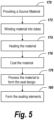
- the sealing element formation system 140 can provide the source material, step 170, via the material source unit 142.
- the material is preferably an elastomer material that can be provided or supplied in any selected form, such as sheets.
- the elastomer source material is then wound into elongated structures or tubes, step 174, by the winding machine 144.
- the elastomer tubes are then heated to form a substantially homogeneous product for a selected period of time, step 174.
- the heated source material tube can then be coated with a suitable coating material by the coating unit 148, step 176.
- the coating material can be any suitable material, such as a resin material, such that when the heated source material is coated, the coated material is sufficiently stiff for subsequent machining on any conventional chipping or lathing machine.
- the outer resin layer allows the coated material to be secured in and to be processed by the turning or lathing machine 150.
- the turning machine 150 can be employed to machine or cut any type of contour into the generally rectangular elastomer source material.
- the turning is preferably done by machining, carving, cutting or chipping material away from the tube until the outer dimensions and contours (e.g., profile) of the tube relatively match or are complementary in shape with the specific dimensions of the channel or groove, step 178.
- the coated material can be processed or machined along the outer surface so as to create the cross-sectional profile of the sealing elements 80, 82 and 88.
- the illustrated formation system 140 can also include a cutting unit 152, which can be integrated into the turning machine 150 or can be a separate and distinct unit 152, that includes one or more cutting elements suitable for cutting the material.
- the cutting unit 152 can be employed to cut the turned material into the individual annular or ring-like sealing elements, step 180.
Landscapes
- Engineering & Computer Science (AREA)
- General Engineering & Computer Science (AREA)
- Mechanical Engineering (AREA)
- Mechanical Sealing (AREA)
- Gasket Seals (AREA)
Claims (4)
- Gleitringdichtung (10) zum Montieren um eine Welle, umfassendeine Halterbaugruppe (20) mit einem Hauptkörper (22) mit einer inneren Oberfläche (24) und einer gegenüberliegenden äußeren Oberfläche (26) und einer ersten Nut (32), die in der inneren Oberfläche der Halterbaugruppe ausgebildet ist, und einer zweiten Nut (34), die in der inneren Oberfläche der Halterbaugruppe ausgebildet ist,einen rotierenden Dichtring (90), der an die Halterbaugruppe gekoppelt ist,einen stationären Dichtring (100), der benachbart zu dem rotierenden Dichtring (90) angeordnet ist,ein erstes Dichtungselement (80) zum Sitzen innerhalb der ersten Nut (32) und mit einer Form, die im Wesentlichen komplementär zu einer Form der ersten Nut ist, um die erste Nut im Wesentlichen vollständig auszufüllen, undein zweites Dichtungselement (82) zum Sitzen innerhalb der zweiten Nut (34) und mit einer Form, die im Wesentlichen komplementär zu einer Form der zweiten Nut ist, um die zweite Nut im Wesentlichen vollständig auszufüllen,wobei der Hauptkörper (22) der Halterbaugruppe (20) eine oder mehrere Befestigungselement-Aufnahmeöffnungen (36) aufweist, die darin ausgebildet sind und sich zwischen der inneren Oberfläche (24) und der äußeren Oberfläche (26) erstrecken und dazu bemessen und konfiguriert sind, dass ein Befestigungselement (38) darin sitzt.
- Gleitringdichtung nach Anspruch 1, ferner umfassendeine erste und zweite Abdecknut (40, 50), die in der äußeren Oberfläche (26) der Halterbaugruppe (20) ausgebildet sind, wobei die erste Abdecknut (40) auf einer Seite der Befestigungselement-Aufnahmeöffnung (36) ausgebildet ist und die zweite Abdecknut (50) auf der anderen Seite der Befestigungselement-Aufnahmeöffnung (36) ausgebildet ist, undein Dichtungsabdeckelement (110) mit einem Hauptkörper (112) mit einem ersten Schenkelabschnitt (118), einem gegenüberliegenden zweiten Schenkelabschnitt (116) und einem Zwischenabschnitt (114), der zwischen dem ersten und zweiten Schenkelabschnitt (116, 118) angeordnet und an diese gekoppelt ist,wobei der erste Schenkelabschnitt (118) des Dichtungsabdeckelements (110) dazu bemessen und konfiguriert ist, dass er innerhalb der ersten Abdecknut (40) sitzt, der zweite Schenkelabschnitt (116) des Dichtungsabdeckelements (110) dazu bemessen und konfiguriert ist, dass er innerhalb der zweiten Abdecknut (50) sitzt, und der Zwischenabschnitt (114) des Dichtungsabdeckelements (110) die Befestigungselement-Aufnahmeöffnung (36) abdeckt.
- Gleitringdichtung nach Anspruch 2, wobei der erste Schenkelabschnitt (118) dazu bemessen und konfiguriert ist, die erste Abdecknut (40) im Wesentlichen vollständig auszufüllen, und der zweite Schenkelabschnitt (116) dazu bemessen und konfiguriert ist, die zweite Abdecknut (50) im Wesentlichen vollständig auszufüllen.
- Gleitringdichtung nach Anspruch 2, wobei der Zwischenabschnitt (114) des Dichtungsabdeckelements (110) eine obere Oberfläche (120) und eine gegenüberliegende untere Oberfläche (126) aufweist und der erste und zweite Schenkelabschnitt (116, 118) jeweils eine obere Oberfläche (122) und eine gegenüberliegende untere Oberfläche (128) aufweisen,
wobei die obere Oberfläche (120) des Zwischenabschnitts (114) radial und axial von der oberen Oberfläche (122) des ersten und zweiten Schenkelabschnitts (116, 118) beabstandet ist und die untere Oberfläche (126) des Zwischenabschnitts (114) radial und axial von der unteren Oberfläche (128) des ersten und zweiten Schenkelabschnitts (116, 118) beabstandet ist.
Applications Claiming Priority (2)
| Application Number | Priority Date | Filing Date | Title |
|---|---|---|---|
| US201962832206P | 2019-04-10 | 2019-04-10 | |
| PCT/US2020/027430 WO2020210464A1 (en) | 2019-04-10 | 2020-04-09 | Method of forming sealing elements for use in mechanical seal |
Publications (3)
| Publication Number | Publication Date |
|---|---|
| EP3953284A1 EP3953284A1 (de) | 2022-02-16 |
| EP3953284A4 EP3953284A4 (de) | 2023-08-02 |
| EP3953284B1 true EP3953284B1 (de) | 2025-03-12 |
Family
ID=72749389
Family Applications (1)
| Application Number | Title | Priority Date | Filing Date |
|---|---|---|---|
| EP20788069.1A Active EP3953284B1 (de) | 2019-04-10 | 2020-04-09 | Verfahren zur formung von dichtungselementen zur verwendung in der mechanischen abdichtung |
Country Status (11)
| Country | Link |
|---|---|
| US (1) | US11835140B2 (de) |
| EP (1) | EP3953284B1 (de) |
| JP (2) | JP7717615B2 (de) |
| AU (1) | AU2020272867A1 (de) |
| BR (1) | BR112021020167A2 (de) |
| CA (1) | CA3136233A1 (de) |
| CL (1) | CL2021002634A1 (de) |
| CO (1) | CO2021013609A2 (de) |
| FI (1) | FI3953284T3 (de) |
| MX (1) | MX2021012245A (de) |
| WO (1) | WO2020210464A1 (de) |
Families Citing this family (1)
| Publication number | Priority date | Publication date | Assignee | Title |
|---|---|---|---|---|
| DE102023103127A1 (de) * | 2023-02-09 | 2024-08-14 | Eagleburgmann Germany Gmbh & Co. Kg | Gleitringdichtungsanordnung |
Family Cites Families (12)
| Publication number | Priority date | Publication date | Assignee | Title |
|---|---|---|---|---|
| US2802513A (en) * | 1955-12-06 | 1957-08-13 | Firestone Tire & Rubber Co | Method of making strain-free gaskets |
| US3697348A (en) | 1969-07-09 | 1972-10-10 | Farnam Co F D | Method of making gaskets |
| US3857156A (en) * | 1973-12-19 | 1974-12-31 | Federal Mogul Corp | Method of making tetrafluoroethylene sealing elements with hydrodynamic action |
| DE69121710T2 (de) * | 1991-02-08 | 1997-01-02 | Nippon Pillar Packing | Gleitringdichtung |
| US5676030A (en) | 1995-08-14 | 1997-10-14 | Crudgington Machine Tools, Inc. | Multi-spindle CNC lathe |
| WO2002027197A2 (en) * | 2000-09-29 | 2002-04-04 | A.W. Chesterton Company | Spacing element for centering components in a mechanical seal and for promoting circulation of a seal fluid therein |
| US7699579B2 (en) | 2005-02-18 | 2010-04-20 | Yandle Ii S Elwood | Mechanical pump seal |
| CN202883454U (zh) | 2012-07-19 | 2013-04-17 | 上海德宝密封件有限公司 | 适用于杂质泵的高可靠性的双向轴密封装置 |
| RU2549009C1 (ru) * | 2013-12-18 | 2015-04-20 | Федеральное Государственное унитарное предприятие "Российский Федеральный ядерный центр-Всероссийский научно-исследовательский институт экспериментальной физики-ФГУП "РФЯЦ-ВНИИЭФ" | Затвор для герметичного перекрытия полости сосуда |
| SE539433C2 (sv) | 2015-12-11 | 2017-09-19 | Roplan Holding Ab | Hållaranordning för att applicera ett tätningselement på en axel, tätningsanordning innefattande en sådan hållaranordning samt hydrodynamisk maskin innefattande sådan tätningsanordning |
| CN106321503B (zh) | 2016-08-30 | 2019-05-17 | 宁波天工机械密封有限公司 | 一种食品设备用机械密封 |
| DE102017214132B4 (de) * | 2017-08-14 | 2020-03-26 | Eagleburgmann Germany Gmbh & Co. Kg | Gleitringdichtungsanordnung sowie Gleitringdichtungs-Baukasten |
-
2020
- 2020-04-09 EP EP20788069.1A patent/EP3953284B1/de active Active
- 2020-04-09 MX MX2021012245A patent/MX2021012245A/es unknown
- 2020-04-09 CA CA3136233A patent/CA3136233A1/en active Pending
- 2020-04-09 JP JP2021559806A patent/JP7717615B2/ja active Active
- 2020-04-09 WO PCT/US2020/027430 patent/WO2020210464A1/en not_active Ceased
- 2020-04-09 BR BR112021020167A patent/BR112021020167A2/pt unknown
- 2020-04-09 FI FIEP20788069.1T patent/FI3953284T3/fi active
- 2020-04-09 US US16/844,371 patent/US11835140B2/en active Active
- 2020-04-09 AU AU2020272867A patent/AU2020272867A1/en not_active Abandoned
-
2021
- 2021-10-08 CL CL2021002634A patent/CL2021002634A1/es unknown
- 2021-10-12 CO CONC2021/0013609A patent/CO2021013609A2/es unknown
-
2025
- 2025-07-23 JP JP2025123201A patent/JP2025148590A/ja active Pending
Also Published As
| Publication number | Publication date |
|---|---|
| US11835140B2 (en) | 2023-12-05 |
| EP3953284A1 (de) | 2022-02-16 |
| FI3953284T3 (fi) | 2025-04-14 |
| US20200325992A1 (en) | 2020-10-15 |
| EP3953284A4 (de) | 2023-08-02 |
| CO2021013609A2 (es) | 2022-01-17 |
| JP2025148590A (ja) | 2025-10-07 |
| BR112021020167A2 (pt) | 2021-12-21 |
| AU2020272867A1 (en) | 2021-11-18 |
| JP2022526828A (ja) | 2022-05-26 |
| CL2021002634A1 (es) | 2022-05-13 |
| CA3136233A1 (en) | 2020-10-15 |
| MX2021012245A (es) | 2021-12-10 |
| WO2020210464A1 (en) | 2020-10-15 |
| JP7717615B2 (ja) | 2025-08-04 |
Similar Documents
| Publication | Publication Date | Title |
|---|---|---|
| EP3908772B1 (de) | Dichtungsanordnung mit mehreren komponenten | |
| US2760794A (en) | Vibration rings for mechanical seals | |
| JP6029700B2 (ja) | 回転するシャフト用のダブルシール装置及び該ダブルシール装置を備えるポンプ | |
| JP2025148590A (ja) | 密封要素を形成するための方法 | |
| US4334687A (en) | Shaft seal with multi-slitted sleeve | |
| EP2145123B1 (de) | Mechanische verschlussvorrichtung und pumpe | |
| US20120068417A1 (en) | Seal And Procedure For Its Production | |
| JP2015152033A (ja) | 流路切り替えバルブおよび当該バルブを用いた液体クロマトグフラフ装置 | |
| CN1146697C (zh) | 单向阀 | |
| US20050035554A1 (en) | Damper device for mechanical seals | |
| WO2007048010A2 (en) | Elastomer spring mechanical seal | |
| JPH01210665A (ja) | シャフトシールユニット | |
| JP2022003281A (ja) | ベローズバルブとベローズバルブの製造方法 | |
| US3391941A (en) | Shaft-sealing system | |
| JP2002235856A (ja) | 密封装置 | |
| MXPA05001336A (es) | Ensamble de sello para bombeo giratorio. | |
| US6942221B2 (en) | Seal having gaps | |
| US11441684B2 (en) | Sealing cover element in a mechanical seal | |
| CA2932197A1 (en) | Sealing system and sealing ring | |
| US10954806B2 (en) | Seal for a gap between an outer and an inner cylindrical surface | |
| GB2214995A (en) | Seals | |
| JPH10122376A (ja) | オイルシール |
Legal Events
| Date | Code | Title | Description |
|---|---|---|---|
| STAA | Information on the status of an ep patent application or granted ep patent |
Free format text: STATUS: THE INTERNATIONAL PUBLICATION HAS BEEN MADE |
|
| PUAI | Public reference made under article 153(3) epc to a published international application that has entered the european phase |
Free format text: ORIGINAL CODE: 0009012 |
|
| STAA | Information on the status of an ep patent application or granted ep patent |
Free format text: STATUS: REQUEST FOR EXAMINATION WAS MADE |
|
| 17P | Request for examination filed |
Effective date: 20211103 |
|
| AK | Designated contracting states |
Kind code of ref document: A1 Designated state(s): AL AT BE BG CH CY CZ DE DK EE ES FI FR GB GR HR HU IE IS IT LI LT LU LV MC MK MT NL NO PL PT RO RS SE SI SK SM TR |
|
| DAV | Request for validation of the european patent (deleted) | ||
| DAX | Request for extension of the european patent (deleted) | ||
| RIC1 | Information provided on ipc code assigned before grant |
Ipc: B29L 31/26 20060101ALN20221221BHEP Ipc: B29C 53/80 20060101ALI20221221BHEP Ipc: B29C 53/56 20060101ALI20221221BHEP Ipc: B29C 35/02 20060101ALI20221221BHEP Ipc: B29C 59/02 20060101ALI20221221BHEP Ipc: F16J 15/10 20060101ALI20221221BHEP Ipc: B65H 81/06 20060101AFI20221221BHEP |
|
| P01 | Opt-out of the competence of the unified patent court (upc) registered |
Effective date: 20230523 |
|
| A4 | Supplementary search report drawn up and despatched |
Effective date: 20230705 |
|
| RIC1 | Information provided on ipc code assigned before grant |
Ipc: B29L 31/26 20060101ALN20230629BHEP Ipc: B29C 53/80 20060101ALI20230629BHEP Ipc: B29C 53/56 20060101ALI20230629BHEP Ipc: B29C 35/02 20060101ALI20230629BHEP Ipc: B29C 59/02 20060101ALI20230629BHEP Ipc: F16J 15/10 20060101ALI20230629BHEP Ipc: B65H 81/06 20060101AFI20230629BHEP |
|
| GRAP | Despatch of communication of intention to grant a patent |
Free format text: ORIGINAL CODE: EPIDOSNIGR1 |
|
| STAA | Information on the status of an ep patent application or granted ep patent |
Free format text: STATUS: GRANT OF PATENT IS INTENDED |
|
| RIC1 | Information provided on ipc code assigned before grant |
Ipc: B29L 31/26 20060101ALN20240912BHEP Ipc: B29C 53/80 20060101ALI20240912BHEP Ipc: B29C 53/56 20060101ALI20240912BHEP Ipc: B29C 35/02 20060101ALI20240912BHEP Ipc: B29C 59/02 20060101ALI20240912BHEP Ipc: F16J 15/10 20060101ALI20240912BHEP Ipc: B65H 81/06 20060101AFI20240912BHEP |
|
| INTG | Intention to grant announced |
Effective date: 20241008 |
|
| GRAS | Grant fee paid |
Free format text: ORIGINAL CODE: EPIDOSNIGR3 |
|
| GRAA | (expected) grant |
Free format text: ORIGINAL CODE: 0009210 |
|
| STAA | Information on the status of an ep patent application or granted ep patent |
Free format text: STATUS: THE PATENT HAS BEEN GRANTED |
|
| AK | Designated contracting states |
Kind code of ref document: B1 Designated state(s): AL AT BE BG CH CY CZ DE DK EE ES FI FR GB GR HR HU IE IS IT LI LT LU LV MC MK MT NL NO PL PT RO RS SE SI SK SM TR |
|
| REG | Reference to a national code |
Ref country code: GB Ref legal event code: FG4D |
|
| REG | Reference to a national code |
Ref country code: CH Ref legal event code: EP |
|
| REG | Reference to a national code |
Ref country code: DE Ref legal event code: R096 Ref document number: 602020047636 Country of ref document: DE |
|
| REG | Reference to a national code |
Ref country code: IE Ref legal event code: FG4D |
|
| REG | Reference to a national code |
Ref country code: FI Ref legal event code: FGE |
|
| REG | Reference to a national code |
Ref country code: SE Ref legal event code: TRGR |
|
| PG25 | Lapsed in a contracting state [announced via postgrant information from national office to epo] |
Ref country code: RS Free format text: LAPSE BECAUSE OF FAILURE TO SUBMIT A TRANSLATION OF THE DESCRIPTION OR TO PAY THE FEE WITHIN THE PRESCRIBED TIME-LIMIT Effective date: 20250612 |
|
| PGFP | Annual fee paid to national office [announced via postgrant information from national office to epo] |
Ref country code: FI Payment date: 20250526 Year of fee payment: 6 |
|
| PGFP | Annual fee paid to national office [announced via postgrant information from national office to epo] |
Ref country code: DE Payment date: 20250422 Year of fee payment: 6 |
|
| PG25 | Lapsed in a contracting state [announced via postgrant information from national office to epo] |
Ref country code: ES Free format text: LAPSE BECAUSE OF FAILURE TO SUBMIT A TRANSLATION OF THE DESCRIPTION OR TO PAY THE FEE WITHIN THE PRESCRIBED TIME-LIMIT Effective date: 20250312 |
|
| REG | Reference to a national code |
Ref country code: LT Ref legal event code: MG9D |
|
| PG25 | Lapsed in a contracting state [announced via postgrant information from national office to epo] |
Ref country code: NO Free format text: LAPSE BECAUSE OF FAILURE TO SUBMIT A TRANSLATION OF THE DESCRIPTION OR TO PAY THE FEE WITHIN THE PRESCRIBED TIME-LIMIT Effective date: 20250612 |
|
| PG25 | Lapsed in a contracting state [announced via postgrant information from national office to epo] |
Ref country code: HR Free format text: LAPSE BECAUSE OF FAILURE TO SUBMIT A TRANSLATION OF THE DESCRIPTION OR TO PAY THE FEE WITHIN THE PRESCRIBED TIME-LIMIT Effective date: 20250312 |
|
| REG | Reference to a national code |
Ref country code: NL Ref legal event code: MP Effective date: 20250312 |
|
| PG25 | Lapsed in a contracting state [announced via postgrant information from national office to epo] |
Ref country code: LV Free format text: LAPSE BECAUSE OF FAILURE TO SUBMIT A TRANSLATION OF THE DESCRIPTION OR TO PAY THE FEE WITHIN THE PRESCRIBED TIME-LIMIT Effective date: 20250312 |
|
| PG25 | Lapsed in a contracting state [announced via postgrant information from national office to epo] |
Ref country code: GR Free format text: LAPSE BECAUSE OF FAILURE TO SUBMIT A TRANSLATION OF THE DESCRIPTION OR TO PAY THE FEE WITHIN THE PRESCRIBED TIME-LIMIT Effective date: 20250613 Ref country code: BG Free format text: LAPSE BECAUSE OF FAILURE TO SUBMIT A TRANSLATION OF THE DESCRIPTION OR TO PAY THE FEE WITHIN THE PRESCRIBED TIME-LIMIT Effective date: 20250312 |
|
| PGFP | Annual fee paid to national office [announced via postgrant information from national office to epo] |
Ref country code: SE Payment date: 20250506 Year of fee payment: 6 |
|
| REG | Reference to a national code |
Ref country code: AT Ref legal event code: MK05 Ref document number: 1774895 Country of ref document: AT Kind code of ref document: T Effective date: 20250312 |
|
| PG25 | Lapsed in a contracting state [announced via postgrant information from national office to epo] |
Ref country code: NL Free format text: LAPSE BECAUSE OF FAILURE TO SUBMIT A TRANSLATION OF THE DESCRIPTION OR TO PAY THE FEE WITHIN THE PRESCRIBED TIME-LIMIT Effective date: 20250312 |
|
| PG25 | Lapsed in a contracting state [announced via postgrant information from national office to epo] |
Ref country code: SM Free format text: LAPSE BECAUSE OF FAILURE TO SUBMIT A TRANSLATION OF THE DESCRIPTION OR TO PAY THE FEE WITHIN THE PRESCRIBED TIME-LIMIT Effective date: 20250312 |
|
| PG25 | Lapsed in a contracting state [announced via postgrant information from national office to epo] |
Ref country code: PT Free format text: LAPSE BECAUSE OF FAILURE TO SUBMIT A TRANSLATION OF THE DESCRIPTION OR TO PAY THE FEE WITHIN THE PRESCRIBED TIME-LIMIT Effective date: 20250714 |
|
| PG25 | Lapsed in a contracting state [announced via postgrant information from national office to epo] |
Ref country code: IT Free format text: LAPSE BECAUSE OF FAILURE TO SUBMIT A TRANSLATION OF THE DESCRIPTION OR TO PAY THE FEE WITHIN THE PRESCRIBED TIME-LIMIT Effective date: 20250312 Ref country code: PL Free format text: LAPSE BECAUSE OF FAILURE TO SUBMIT A TRANSLATION OF THE DESCRIPTION OR TO PAY THE FEE WITHIN THE PRESCRIBED TIME-LIMIT Effective date: 20250312 |
|
| PG25 | Lapsed in a contracting state [announced via postgrant information from national office to epo] |
Ref country code: AT Free format text: LAPSE BECAUSE OF FAILURE TO SUBMIT A TRANSLATION OF THE DESCRIPTION OR TO PAY THE FEE WITHIN THE PRESCRIBED TIME-LIMIT Effective date: 20250312 |
|
| PG25 | Lapsed in a contracting state [announced via postgrant information from national office to epo] |
Ref country code: EE Free format text: LAPSE BECAUSE OF FAILURE TO SUBMIT A TRANSLATION OF THE DESCRIPTION OR TO PAY THE FEE WITHIN THE PRESCRIBED TIME-LIMIT Effective date: 20250312 Ref country code: CZ Free format text: LAPSE BECAUSE OF FAILURE TO SUBMIT A TRANSLATION OF THE DESCRIPTION OR TO PAY THE FEE WITHIN THE PRESCRIBED TIME-LIMIT Effective date: 20250312 |
|
| PG25 | Lapsed in a contracting state [announced via postgrant information from national office to epo] |
Ref country code: RO Free format text: LAPSE BECAUSE OF FAILURE TO SUBMIT A TRANSLATION OF THE DESCRIPTION OR TO PAY THE FEE WITHIN THE PRESCRIBED TIME-LIMIT Effective date: 20250312 |
|
| PG25 | Lapsed in a contracting state [announced via postgrant information from national office to epo] |
Ref country code: SK Free format text: LAPSE BECAUSE OF FAILURE TO SUBMIT A TRANSLATION OF THE DESCRIPTION OR TO PAY THE FEE WITHIN THE PRESCRIBED TIME-LIMIT Effective date: 20250312 |
|
| PG25 | Lapsed in a contracting state [announced via postgrant information from national office to epo] |
Ref country code: IS Free format text: LAPSE BECAUSE OF FAILURE TO SUBMIT A TRANSLATION OF THE DESCRIPTION OR TO PAY THE FEE WITHIN THE PRESCRIBED TIME-LIMIT Effective date: 20250712 |
|
| REG | Reference to a national code |
Ref country code: CH Ref legal event code: H13 Free format text: ST27 STATUS EVENT CODE: U-0-0-H10-H13 (AS PROVIDED BY THE NATIONAL OFFICE) Effective date: 20251125 |
|
| PG25 | Lapsed in a contracting state [announced via postgrant information from national office to epo] |
Ref country code: LU Free format text: LAPSE BECAUSE OF NON-PAYMENT OF DUE FEES Effective date: 20250409 |
|
| REG | Reference to a national code |
Ref country code: DE Ref legal event code: R097 Ref document number: 602020047636 Country of ref document: DE |
|
| PG25 | Lapsed in a contracting state [announced via postgrant information from national office to epo] |
Ref country code: MC Free format text: LAPSE BECAUSE OF FAILURE TO SUBMIT A TRANSLATION OF THE DESCRIPTION OR TO PAY THE FEE WITHIN THE PRESCRIBED TIME-LIMIT Effective date: 20250312 |
|
| REG | Reference to a national code |
Ref country code: BE Ref legal event code: MM Effective date: 20250430 |
|
| PG25 | Lapsed in a contracting state [announced via postgrant information from national office to epo] |
Ref country code: DK Free format text: LAPSE BECAUSE OF FAILURE TO SUBMIT A TRANSLATION OF THE DESCRIPTION OR TO PAY THE FEE WITHIN THE PRESCRIBED TIME-LIMIT Effective date: 20250312 |
|
| PG25 | Lapsed in a contracting state [announced via postgrant information from national office to epo] |
Ref country code: BE Free format text: LAPSE BECAUSE OF NON-PAYMENT OF DUE FEES Effective date: 20250430 |
|
| PLBE | No opposition filed within time limit |
Free format text: ORIGINAL CODE: 0009261 |
|
| STAA | Information on the status of an ep patent application or granted ep patent |
Free format text: STATUS: NO OPPOSITION FILED WITHIN TIME LIMIT |
|
| PG25 | Lapsed in a contracting state [announced via postgrant information from national office to epo] |
Ref country code: CH Free format text: LAPSE BECAUSE OF NON-PAYMENT OF DUE FEES Effective date: 20250430 |
|
| REG | Reference to a national code |
Ref country code: CH Ref legal event code: L10 Free format text: ST27 STATUS EVENT CODE: U-0-0-L10-L00 (AS PROVIDED BY THE NATIONAL OFFICE) Effective date: 20260121 |
|
| 26N | No opposition filed |
Effective date: 20251215 |
|
| GBPC | Gb: european patent ceased through non-payment of renewal fee |
Effective date: 20250612 |
|
| PG25 | Lapsed in a contracting state [announced via postgrant information from national office to epo] |
Ref country code: GB Free format text: LAPSE BECAUSE OF NON-PAYMENT OF DUE FEES Effective date: 20250612 |
|
| PG25 | Lapsed in a contracting state [announced via postgrant information from national office to epo] |
Ref country code: IE Free format text: LAPSE BECAUSE OF NON-PAYMENT OF DUE FEES Effective date: 20250409 |
|
| PG25 | Lapsed in a contracting state [announced via postgrant information from national office to epo] |
Ref country code: FR Free format text: LAPSE BECAUSE OF NON-PAYMENT OF DUE FEES Effective date: 20250512 |