EP3953113B1 - Procédé de revêtement et système de revêtement correspondant - Google Patents
Procédé de revêtement et système de revêtement correspondant Download PDFInfo
- Publication number
- EP3953113B1 EP3953113B1 EP20726718.8A EP20726718A EP3953113B1 EP 3953113 B1 EP3953113 B1 EP 3953113B1 EP 20726718 A EP20726718 A EP 20726718A EP 3953113 B1 EP3953113 B1 EP 3953113B1
- Authority
- EP
- European Patent Office
- Prior art keywords
- coating
- path
- component
- movement
- robot
- Prior art date
- Legal status (The legal status is an assumption and is not a legal conclusion. Google has not performed a legal analysis and makes no representation as to the accuracy of the status listed.)
- Active
Links
- 238000000576 coating method Methods 0.000 title claims description 162
- 239000011248 coating agent Substances 0.000 title claims description 151
- 238000009434 installation Methods 0.000 title claims description 7
- 238000005259 measurement Methods 0.000 claims description 58
- 239000003973 paint Substances 0.000 claims description 19
- 230000001133 acceleration Effects 0.000 claims description 8
- 230000003068 static effect Effects 0.000 claims description 2
- 238000012937 correction Methods 0.000 description 16
- 238000010422 painting Methods 0.000 description 16
- CLOMYZFHNHFSIQ-UHFFFAOYSA-N clonixin Chemical compound CC1=C(Cl)C=CC=C1NC1=NC=CC=C1C(O)=O CLOMYZFHNHFSIQ-UHFFFAOYSA-N 0.000 description 4
- 238000004364 calculation method Methods 0.000 description 3
- 238000000034 method Methods 0.000 description 3
- 238000013459 approach Methods 0.000 description 2
- 230000001419 dependent effect Effects 0.000 description 2
- 238000001514 detection method Methods 0.000 description 2
- 238000005457 optimization Methods 0.000 description 2
- 238000011160 research Methods 0.000 description 2
- 239000007921 spray Substances 0.000 description 2
- 230000006978 adaptation Effects 0.000 description 1
- 238000000889 atomisation Methods 0.000 description 1
- 238000009529 body temperature measurement Methods 0.000 description 1
- 238000011960 computer-aided design Methods 0.000 description 1
- 238000011161 development Methods 0.000 description 1
- 230000018109 developmental process Effects 0.000 description 1
- 230000002452 interceptive effect Effects 0.000 description 1
- 238000012423 maintenance Methods 0.000 description 1
- 238000012545 processing Methods 0.000 description 1
Images


Classifications
-
- B—PERFORMING OPERATIONS; TRANSPORTING
- B05—SPRAYING OR ATOMISING IN GENERAL; APPLYING FLUENT MATERIALS TO SURFACES, IN GENERAL
- B05B—SPRAYING APPARATUS; ATOMISING APPARATUS; NOZZLES
- B05B13/00—Machines or plants for applying liquids or other fluent materials to surfaces of objects or other work by spraying, not covered by groups B05B1/00 - B05B11/00
- B05B13/02—Means for supporting work; Arrangement or mounting of spray heads; Adaptation or arrangement of means for feeding work
- B05B13/04—Means for supporting work; Arrangement or mounting of spray heads; Adaptation or arrangement of means for feeding work the spray heads being moved during spraying operation
- B05B13/0431—Means for supporting work; Arrangement or mounting of spray heads; Adaptation or arrangement of means for feeding work the spray heads being moved during spraying operation with spray heads moved by robots or articulated arms, e.g. for applying liquid or other fluent material to 3D-surfaces
-
- B—PERFORMING OPERATIONS; TRANSPORTING
- B25—HAND TOOLS; PORTABLE POWER-DRIVEN TOOLS; MANIPULATORS
- B25J—MANIPULATORS; CHAMBERS PROVIDED WITH MANIPULATION DEVICES
- B25J11/00—Manipulators not otherwise provided for
- B25J11/0075—Manipulators for painting or coating
-
- B—PERFORMING OPERATIONS; TRANSPORTING
- B05—SPRAYING OR ATOMISING IN GENERAL; APPLYING FLUENT MATERIALS TO SURFACES, IN GENERAL
- B05B—SPRAYING APPARATUS; ATOMISING APPARATUS; NOZZLES
- B05B13/00—Machines or plants for applying liquids or other fluent materials to surfaces of objects or other work by spraying, not covered by groups B05B1/00 - B05B11/00
- B05B13/02—Means for supporting work; Arrangement or mounting of spray heads; Adaptation or arrangement of means for feeding work
- B05B13/04—Means for supporting work; Arrangement or mounting of spray heads; Adaptation or arrangement of means for feeding work the spray heads being moved during spraying operation
- B05B13/0447—Installation or apparatus for applying liquid or other fluent material to conveyed separate articles
- B05B13/0452—Installation or apparatus for applying liquid or other fluent material to conveyed separate articles the conveyed articles being vehicle bodies
-
- B—PERFORMING OPERATIONS; TRANSPORTING
- B05—SPRAYING OR ATOMISING IN GENERAL; APPLYING FLUENT MATERIALS TO SURFACES, IN GENERAL
- B05B—SPRAYING APPARATUS; ATOMISING APPARATUS; NOZZLES
- B05B12/00—Arrangements for controlling delivery; Arrangements for controlling the spray area
-
- B—PERFORMING OPERATIONS; TRANSPORTING
- B05—SPRAYING OR ATOMISING IN GENERAL; APPLYING FLUENT MATERIALS TO SURFACES, IN GENERAL
- B05B—SPRAYING APPARATUS; ATOMISING APPARATUS; NOZZLES
- B05B12/00—Arrangements for controlling delivery; Arrangements for controlling the spray area
- B05B12/08—Arrangements for controlling delivery; Arrangements for controlling the spray area responsive to condition of liquid or other fluent material to be discharged, of ambient medium or of target ; responsive to condition of spray devices or of supply means, e.g. pipes, pumps or their drive means
- B05B12/12—Arrangements for controlling delivery; Arrangements for controlling the spray area responsive to condition of liquid or other fluent material to be discharged, of ambient medium or of target ; responsive to condition of spray devices or of supply means, e.g. pipes, pumps or their drive means responsive to conditions of ambient medium or target, e.g. humidity, temperature position or movement of the target relative to the spray apparatus
- B05B12/122—Arrangements for controlling delivery; Arrangements for controlling the spray area responsive to condition of liquid or other fluent material to be discharged, of ambient medium or of target ; responsive to condition of spray devices or of supply means, e.g. pipes, pumps or their drive means responsive to conditions of ambient medium or target, e.g. humidity, temperature position or movement of the target relative to the spray apparatus responsive to presence or shape of target
-
- B—PERFORMING OPERATIONS; TRANSPORTING
- B25—HAND TOOLS; PORTABLE POWER-DRIVEN TOOLS; MANIPULATORS
- B25J—MANIPULATORS; CHAMBERS PROVIDED WITH MANIPULATION DEVICES
- B25J13/00—Controls for manipulators
- B25J13/08—Controls for manipulators by means of sensing devices, e.g. viewing or touching devices
-
- B—PERFORMING OPERATIONS; TRANSPORTING
- B25—HAND TOOLS; PORTABLE POWER-DRIVEN TOOLS; MANIPULATORS
- B25J—MANIPULATORS; CHAMBERS PROVIDED WITH MANIPULATION DEVICES
- B25J9/00—Programme-controlled manipulators
- B25J9/16—Programme controls
- B25J9/1656—Programme controls characterised by programming, planning systems for manipulators
- B25J9/1664—Programme controls characterised by programming, planning systems for manipulators characterised by motion, path, trajectory planning
-
- B—PERFORMING OPERATIONS; TRANSPORTING
- B25—HAND TOOLS; PORTABLE POWER-DRIVEN TOOLS; MANIPULATORS
- B25J—MANIPULATORS; CHAMBERS PROVIDED WITH MANIPULATION DEVICES
- B25J9/00—Programme-controlled manipulators
- B25J9/16—Programme controls
- B25J9/1679—Programme controls characterised by the tasks executed
- B25J9/1684—Tracking a line or surface by means of sensors
-
- B—PERFORMING OPERATIONS; TRANSPORTING
- B25—HAND TOOLS; PORTABLE POWER-DRIVEN TOOLS; MANIPULATORS
- B25J—MANIPULATORS; CHAMBERS PROVIDED WITH MANIPULATION DEVICES
- B25J9/00—Programme-controlled manipulators
- B25J9/16—Programme controls
- B25J9/1694—Programme controls characterised by use of sensors other than normal servo-feedback from position, speed or acceleration sensors, perception control, multi-sensor controlled systems, sensor fusion
- B25J9/1697—Vision controlled systems
-
- G—PHYSICS
- G05—CONTROLLING; REGULATING
- G05B—CONTROL OR REGULATING SYSTEMS IN GENERAL; FUNCTIONAL ELEMENTS OF SUCH SYSTEMS; MONITORING OR TESTING ARRANGEMENTS FOR SUCH SYSTEMS OR ELEMENTS
- G05B2219/00—Program-control systems
- G05B2219/30—Nc systems
- G05B2219/37—Measurements
- G05B2219/37563—Ccd, tv camera
-
- G—PHYSICS
- G05—CONTROLLING; REGULATING
- G05B—CONTROL OR REGULATING SYSTEMS IN GENERAL; FUNCTIONAL ELEMENTS OF SUCH SYSTEMS; MONITORING OR TESTING ARRANGEMENTS FOR SUCH SYSTEMS OR ELEMENTS
- G05B2219/00—Program-control systems
- G05B2219/30—Nc systems
- G05B2219/37—Measurements
- G05B2219/37572—Camera, tv, vision
-
- G—PHYSICS
- G05—CONTROLLING; REGULATING
- G05B—CONTROL OR REGULATING SYSTEMS IN GENERAL; FUNCTIONAL ELEMENTS OF SUCH SYSTEMS; MONITORING OR TESTING ARRANGEMENTS FOR SUCH SYSTEMS OR ELEMENTS
- G05B2219/00—Program-control systems
- G05B2219/30—Nc systems
- G05B2219/45—Nc applications
- G05B2219/45013—Spraying, coating, painting
-
- G—PHYSICS
- G05—CONTROLLING; REGULATING
- G05B—CONTROL OR REGULATING SYSTEMS IN GENERAL; FUNCTIONAL ELEMENTS OF SUCH SYSTEMS; MONITORING OR TESTING ARRANGEMENTS FOR SUCH SYSTEMS OR ELEMENTS
- G05B2219/00—Program-control systems
- G05B2219/30—Nc systems
- G05B2219/45—Nc applications
- G05B2219/45065—Sealing, painting robot
Definitions
- the invention relates to a coating method for coating a component (e.g. motor vehicle body component) with a coating agent (e.g. paint). Furthermore, the invention relates to a corresponding coating system.
- a component e.g. motor vehicle body component
- a coating agent e.g. paint
- rotary atomizers are usually used as application devices, which are guided by a multi-axis painting robot with serial robot kinematics along predetermined coating paths over the component surface of the motor vehicle body components to be painted.
- the motor vehicle body components to be painted are usually conveyed through the painting installation by a linear conveyor along a painting line, with the linear conveyor having positioning tolerances.
- the multi-axis painting robot also has positioning tolerances.
- the vehicle body components to be painted also have shape tolerances. As a result, these positioning tolerances can lead to incorrect positioning of the rotary atomizer relative to the motor vehicle body component to be painted.
- a known concept provides that the motor vehicle body components to be painted are measured by a position detection system before painting, the position detection system being able to work with four cameras, for example. Depending on the measured position, alignment and shape of the motor vehicle body component to be painted, the predetermined programmed coating paths can then be adjusted accordingly.
- Another known concept provides for measuring the motor vehicle body components to be painted with mobile, robot-guided systems, with the specified coating paths can then be adjusted depending on the measurement result.
- the measurement of the vehicle body components to be painted is carried out in a separate measurement process independently of the specified programmed coating paths.
- temperature changes during operation can also lead to incorrect positioning of the robot-guided rotary atomizer relative to the motor vehicle body components to be painted.
- the painting robot heats up during operation due to electrical heat loss and friction, which changes the robot geometry, which leads to a corresponding incorrect positioning.
- Temperature-related incorrect positioning of up to 1mm can occur during robot operation.
- the exact position of the surface to be painted is irrelevant, as long as it is not outside the range of the spray cone. However, this does not apply to contrasting roof painting with an overspray-free applicator (e.g. print head).
- Global component measurement using multiple cameras is usually not sufficient to achieve the required positioning accuracy because component tolerances and robot tolerances are not taken into account.
- the positioning error when painting vehicle body components should be less than 1mm.
- the temperature compensation described above is very complex and dependent on the quality of the artefacts, the number and position of the measuring points and the description of the robot model.
- the artefacts are not directly in the application area, so as not to hinder the robots in the actual measurement task.
- such systems for temperature compensation are relatively complex, expensive and require high maintenance.
- the invention is therefore based on the object of creating a correspondingly improved coating method and a corresponding coating system.
- the coating tracks and the measuring track usually run through a surface area of the component to be coated, such as a roof of an automobile body, which surface area is limited by edges that can be measured.
- reference values of the spatial edge point positions and/or the edge point orientations are specified for edge points on the edges of the surface area. These reference values can, for example, be based on a specified CAD model (CAD: Computer Aided Design) can be determined or measured separately.
- CAD Computer Aided Design
- this adjustment can be done using a correction algorithm, which can include, for example, an nth order polynomial with n from 1-6, a cubic spline, a quintic spline, a cubic Bezier curve, or a quintic Bezier curve, to name a few examples to name.
- a correction algorithm can include, for example, an nth order polynomial with n from 1-6, a cubic spline, a quintic spline, a cubic Bezier curve, or a quintic Bezier curve, to name a few examples to name.
- the basic idea of the correction algorithm is that the correction value of a measuring point influences a path point the more, the smaller the distance between the measuring point and the path point.
- the edges are approximated in sections using linear equations.
- Two adjacent measurement points each define a straight line that is valid between the two measurement points or - if there is no other measurement point in one direction - also beyond.
- the XP coordinate is used to determine which section of the equations for the left/right edges belong to this point, and then the XP coordinate is inserted into the corresponding equations.
- the YP coordinate is used to determine which section of the equations for the left/right edges belong to this point and then the YP coordinate is inserted into the corresponding equations.
- the projection in the XZ plane with the left and right edges or the projection in the YZ plane with the start edge and the end edge can be used.
- linear equations of the form z f(x)
- the bordered surface area (e.g. roof of a motor vehicle body) on the component to be coated is measured and coated by two coating robots, the two coating robots preferably being arranged on opposite sides of the surface area, for example on opposite sides a painting line.
- the surface area can then be divided into two sub-areas that are directly adjacent to one another. For example, this can be a left half of the roof and a right half of the roof.
- the first coating robot measures the entire surface area or one of the two partial areas with its measuring system.
- the coating path is then adjusted depending on the spatial measurement by the first coating robot.
- the first coating robot then coats the first partial area (e.g.
- the second coating robot measures the second partial area and adjusts the coating path depending on the spatial measurement. Finally, the second coating robot then coats the second partial area (e.g. the other half of the roof) with the coating agent.
- the second robot can measure its remaining application area by measuring the first application path of the first robot, which at the same time represents the border between the two partial areas.
- the invention preferably takes a completely different approach than the known concepts described at the outset.
- the known concepts aim to improve the positioning accuracy of the robot, for example by compensating for temperature-related positioning errors. An attempt is therefore made to approximate the actual position of the applicator to the specified target position as far as possible.
- the approach according to the invention does not consist in generally improving the absolute accuracy of the robot with regard to positioning, to optimize the application result, but to record all deviations locally through direct measurement on the component to be painted and to increase the application accuracy through individual adaptation of the robot program.
- the same movement should be carried out for the measurement of the component to be applied as for the subsequent application.
- the exact cause of a positioning error e.g. deviations in the component position, the component shape or temperature-related positioning errors
- the coating method according to the invention is preferably used for coating motor vehicle body components. In principle, however, the coating method according to the invention is also suitable for coating other types of components.
- the coating method according to the invention is preferably used for painting components.
- the invention is not limited to paints either, but can in principle also be implemented with other types of coating agents.
- a coating path is specified.
- the coating paths can be specified by manual "teaching".
- the coating path can be generated using software, for example using an offline programming system. Based on the CAD data, application paths are automatically generated that lead across the surface of the component to be coated. The paint impact point of the application device (eg rotary atomizer) should then later be guided along this coating path over the surface of the component to be coated.
- the programming of such coating tracks is known per se from the prior art and is also referred to as "teaching" in accordance with the usual technical terminology.
- the coating method according to the invention preferably also provides that the component to be coated (e.g. motor vehicle body component) is measured by means of a measuring system with regard to position in three-dimensional space, orientation and/or shape.
- the component to be coated e.g. motor vehicle body component
- the programmed coating path is then preferably adjusted accordingly in order to avoid positioning errors.
- the application device e.g. print head or another application device that applies the coating agent with sharp edges and without overspray
- the application device is then preferably guided along the adapted coating path over the surface of the component to be coated, which is preferably done using a multi-axis coating robot.
- the application device then releases the coating agent onto the surface of the component to be coated.
- application device should be understood in general and includes both applicators that atomize the coating agent, e.g. by means of air and/or rotating elements, as well as those that apply the coating agent without atomization, such as print heads or those that emit at least one narrowly defined jet of coating agent (such as eg in DE 10 2013 002 433 A1 , DE 10 2013 002 413 A1 , DE 10 2013 002 412 A1 or DE 10 2013 002 411 A1 described).
- the coating method according to the invention now differs from the known coating method described at the beginning with a robot-guided component measurement, preferably essentially in the steps for spatial measurement of the component to be coated.
- a measuring track is preferably specified, which leads across the surface of the component to be coated, the measuring track essentially corresponding to the coating track.
- a measuring system is then guided along the specified measuring path as part of a measuring movement over the component surface, with the paint impact point of the application device following the specified measuring path, ie a measuring sensor follows the measuring path.
- the component to be coated is then spatially measured by the measuring system.
- the measuring movement preferably essentially corresponds to the later application movement, so that essentially the same temperature-related positioning errors occur during the measuring movement as during the actual application movement. It is therefore no longer necessary to compensate for the temperature-related positioning errors during the actual application movement with complex temperature measurements. Rather, the temperature-related positioning errors can be accepted during the actual application movement because they have already been taken into account in the preceding measurement movement.
- the invention therefore differs from the component measurements with robot-guided measuring systems described at the outset, preferably in that the measurement movement essentially corresponds to the application movement. In contrast to this, the measurement with robot-guided measuring systems has so far been carried out with completely different movements.
- the measurement movement preferably corresponds as precisely as possible to the later application movement. This initially applies to deviations between the spatial position of the ink impact point during the measuring movement on the one hand and during the application movement on the other hand.
- the spatial deviations between the application movement on the one hand and the measurement movement on the other hand should preferably be less than 100 mm, 60 mm, 50 mm, 40 mm, 30 mm, 20 mm, 10 mm, 5 mm, 2 mm or 1 mm.
- the measuring movement should preferably not only correspond as precisely as possible to the later application movement with regard to the position of the ink impact point. Rather, the orientation of the application device during the measurement movement should also correspond as precisely as possible to the later orientation during the application movement.
- the angular deviation of the application device during the measuring movement on the one hand and during the application movement on the other hand should preferably be less than 45°, 30°, 20°, 10°, 5°, 2° or 1°.
- a specific position and orientation of the robot-guided application device cannot usually be realized with just a single robot pose but with different robot poses.
- the concept of a robot pose used in the context of the invention means the large number of axis angles of the robot.
- a specific robot pose can be clearly defined by a vector that contains all axis angles of the robot as components.
- the measurement movement also takes place with the same robot poses as the later application movement.
- the angular deviations of the individual robot axes between the application movement on the one hand and the measurement movement on the other hand should preferably be less than 20°, 10° or 5°.
- the measurement movement should preferably also take place with the same movement dynamics as the later application movement, i.e. with the same path speed of the color impact point, the same path acceleration of the color impact point, the same axis positions of the robot axes, the same axis speeds of the robot axes and/or the same axis accelerations of the robot axes.
- the deviation of the web speed of the ink impact point between the measuring movement and the application movement should preferably be less than 60%, 50%, 40%, 30%, 20%, 10% or even less than 5%. In absolute values, the web speed deviation should preferably be less than 500mm/s, 400mm/s or 300mm/s. With regard to path acceleration, axis speeds of the robot axes and axis accelerations of the robot axes, the deviations between the measurement movement on the one hand and the application movement on the other hand should preferably be less than 10% or 5%.
- the invention does not only claim protection for the coating method according to the invention described above. Rather, the invention also claims protection for a corresponding coating system for coating a component. In particular, this can be a paint shop for painting motor vehicle body components.
- the coating system according to the invention has at least one multi-axis coating robot, which preferably has serial robot kinematics and can guide an application device (e.g. rotary atomizer) along a predetermined coating path over the component surface of the component to be coated.
- an application device e.g. rotary atomizer
- the coating system according to the invention also has a measuring system for spatial measurement of the component to be coated.
- the coating system according to the invention also includes a control unit for controlling the application device and the coating robot and for querying the measuring system.
- the coating system according to the invention is characterized in that the control unit controls the coating robot and the application device and queries the measuring system in such a way that the coating system carries out the coating method according to the invention.
- the measuring system is preferably robot-guided and mounted on the coating robot and is moved by the coating robot over the surface of the component to be coated.
- the measuring system can have a light section sensor or a camera, to name just a few examples.
- the application device can be an atomizer (eg rotary atomizer).
- the application device is an overspray-free application device which, in contrast to an atomizer, does not emit a spray jet but rather a spatially limited jet of coating medium.
- overspray-free application devices are known from the prior art from recent times and are also referred to as print heads.
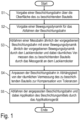
- a coating path is first specified, which leads over the surface of the component to be coated and the desired path of the paint impact point of the application device used (e.g. rotary atomizer).
- the coating path does not reflect the spatial position of the paint impact point, but also the spatial orientation of the application device along the coating path.
- Such a coating path is usually defined by programming, which is also known as "teaching" from the prior art.
- the coating path can also be specified offline.
- a desired movement dynamics for the traversing of the coating web is then specified.
- the movement dynamics here include the speed and the acceleration of the paint impact point along the specified coating path.
- a measurement path similar to the specified coating path is then traversed with similar movement dynamics, with a measuring device guided by the painting robot measuring the component. It is important here that the measuring movement has the smallest possible deviations from the later application movement, so that the positioning errors during the measuring movement correspond as precisely as possible to the positioning errors during the application movement.
- step S4 the coating path specified in step S1 is then adjusted, specifically as a function of the spatial measurement carried out in step S3 during the measuring movement.
- step S5 the optimized coating path is then traversed, with the application device applying the coating agent.
- Steps S1-S4 thus reflect the creation, measurement and optimization of the coating path, while step S5 reflects the actual application operation.
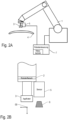
- FIGS. 2A and 2B show in schematic form a coating system according to the invention with a coating robot 1 with a robot flange 2 and an applicator 3 attached to the robot flange 2, such as a rotary atomizer.
- the applicator 3 applies a coating agent to a component 4, which is only shown schematically here.
- a sensor 5 is attached to the robot flange 2 , which has a sensor measuring window 6 and enables the component 4 to be measured.
- the sensor 5 can be a camera-based sensor, but a light section sensor is also possible, for example.
- the coating system includes a control unit 7 which contains a robot controller in order to control the coating robot 1 .
- the control unit 7 contains measurement technology to query the sensor 5 .
- the measurement technology is not necessarily integrated into the robot control. Rather, it can be located in a stand-alone system / PC.
- the control unit 7 then controls the coating robot 1 and queries the sensor 5 in such a way that the coating method according to the invention is carried out.
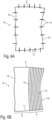
- a circumferential contour measurement of a component surface 8 takes place, which can be, for example, a roof of a motor vehicle body.
- the component surface 8 has edges 9 - 12 which delimit the component surface 8 .
- a circumferential contour measurement of the component surface 8 takes place.
- edge points 14 on the edges 9-12 of the component surface 8 are measured.
- a step S2 the coordinates of the measured edge points 14 are then compared with a reference measurement, it being possible for the corresponding reference values to be specified by a CAD model, for example.
- a step S3 the deviations between the measured values of the edge points 14 and the specified reference values are then calculated.
- a step S4 the measurement results are then forwarded to a robot controller.
- a step S5 the coating tracks 13 are then recalculated in order to take positioning errors into account.
- the Figure 4B shows the corresponding deformed coating webs 13 according to the optimization.
- the coating process in this variant of the invention is carried out by two coating robots which are arranged on opposite sides of a painting line.
- the component surface 8 is divided into two partial surfaces A, B, which can be, for example, a left and a right half of the roof of a motor vehicle body.
- a circumferential contour measurement of the first partial area A of the application area for example in Figure 6A shown right half of the component area 8.
- a step S2 the coordinates of the edge points 14 are then compared with the corresponding coordinates of the reference values in the manner already described above.
- the measurement differences are then calculated in a step S3.
- a step S4 the measurement results are transmitted to a control unit, which then recalculates the coating paths in the partial area A (eg, right half of the roof) in a step S5.
- a step S6 the partial area A is then coated, as in Figure 6B is shown.
- the contour of the second partial surface B of the component surface 8 is also measured, which can be the other half of the roof, for example.
- a comparison is then made with the boundary contour, which can involve a coating web 15 that was painted beforehand in step S6, with this coating web 15 being able to be independent of the coating web 13.
- step S9 a comparison with the reference measurement then takes place again and the measurement differences are calculated in step S10.
- step S11 the measurement results are transmitted to a control unit, which then recalculates the coating paths in step S11.
- step S13 the second partial area B is then applied, as in Figure 6D is shown in dashed lines.
- a roof area is only exemplary. Any other surface, for example a motor vehicle body, can be measured and coated in the same way, for example the A pillar, roof pillar or C pillar.
Claims (16)
- Procédé de revêtement pour le revêtement d'un composant (4) avec un produit de revêtement, avec les étapes suivantes :a) prédétermination d'au moins une bande de revêtement (13, 15) d'un robot de revêtement (1) pour le déplacement d'un point d'impact de peinture d'un appareil d'application (3) le long du composant à revêtir (4), dans lequel l'au moins une bande de revêtement (13, 15) s'étend à travers une zone superficielle du composant à revêtir (4), qui est délimitée par des bords,b) prédétermination de valeurs de référence des positions des points de bords et/ou des orientations des points de bords dans l'espace pour les points de bords sur les bords de la zone superficielle,c) mesure spatiale de la position, de l'orientation et/ou de la forme du composant à revêtir (4) ou d'une partie du composant à revêtir (4) au moyen d'un système de mesure (5), dans lequel les valeurs de mesure des positions de points de bords et/ou des orientations des points de bords sont mesurées sur les bords de la zone superficielle,d) détermination de l'écart entre les valeurs de mesure des positions de points de bords et/ou des orientations des points de bords d'une part et les valeurs de référence des positions de points de bords et/ou des orientations des points de bords d'autre part ete) adaptation de la bande de revêtement (13, 15) en fonction de l'écart entre les valeurs de référence des points de bords et les valeurs de mesure des points de bords,f) déplacement d'un appareil d'application (3) le long de l'au moins une bande de revêtement (13, 15) adaptée sur la surface du composant à revêtir (4) etg) application du produit de revêtement par l'appareil d'application (3) sur la surface du composant à revêtir (4) pendant le déplacement de l'appareil d'application (3) le long de l'au moins une bande de revêtement (13, 15) adaptée.
- Procédé de revêtement selon la revendication 1, caractérisé en ce que l'étape c) comprend en outre, pour la mesure spatiale de la position, de l'orientation et/ou de la forme du composant à revêtir (4) ou d'une partie du composant à revêtir (4) ; les étapes suivantes :c1) prédétermination d'une bande de mesure pour le déplacement du système de mesure (5) au-dessus de la surface du composant à revêtir (4), dans lequel bande de mesure correspond globalement à la bande de revêtement (13, 15),c2) déplacement d'un système de mesure (5) le long de la bande de mesure prédéterminée, dans lequel le point d'impact de la peinture de l'appareil d'application (3) suit la bande de mesure prédéterminée etc3) mesure spatiale du composant à revêtir (4) par le système de mesure (5) pendant le déplacement de mesure le long de la bande de mesure.
- Procédé de revêtement selon la revendication 2, caractérisé en ce que les écarts entre la position dans l'espace du point d'impact de la peinture lors du déplacement de mesure le long de la bande de mesure d'une part et la position dans l'espace du point d'impact de la peinture lors du déplacement d'application le long de la bande de revêtement (13, 15) d'autre part sont inférieures à 40 mm, 30 mm, 20 mm, 10 mm, 5 mm, 2 mm ou 1 mm.
- Procédé de revêtement selon la revendication 2 ou 3, caractérisé en ce que l'appareil d'application (3) présente, lors du déplacement de mesure, globalement la même orientation spatiale que lors du déplacement d'application.
- Procédé de revêtement selon la revendication 4, caractérisé en ce quea) les écarts angulaires entre l'orientation de l'appareil d'application (3) lors du déplacement de mesure d'une part et l'orientation de l'appareil d'application (3) lors du déplacement d'application d'autre part sont inférieurs à 45°, 30°, 20°, 10°, 5°, 2° ou 1° et/oub) les écarts angulaires entre l'orientation des différents axes du robot lors du déplacement de mesure d'une part et l'orientation des différents axes du robot lors du déplacement d'application d'autre part sont inférieurs à 20°, 10° ou 5°.
- Procédé de revêtement selon l'une des revendications précédentes, caractérisé en ce quea) le déplacement d'application a lieu le long de l'au moins une bande de revêtement (13, 15) avec une dynamique de déplacement déterminée,b) le déplacement de mesure a lieu le long de la bande de revêtement (13, 15) avec une dynamique de déplacement déterminée,c) le déplacement de mesure a lieu globalement avec la même dynamique de déplacement que le déplacement d'application, notamment en ce qui concerne la vitesse de bande du point d'impact de la peinture de l'appareil d'application (3) et/ou en ce qui concernant l'accélération de bande du point d'impact de la peinture de l'appareil d'application (3).
- Procédé de revêtement selon la revendication 6, caractérisé en ce quea) les écarts entre la vitesse du point d'impact de la peinture lors du déplacement de mesure d'une part et la vitesse de bande du point d'impact de la peinture lors du déplacement d'application d'autre part sont inférieurs àa1) 60 %, 50 %, 40 %, 30 %, 20 %, 10 % ou 5 % et/oua2) 500 mm/s, 400 mm/s, 300 mm/s,b) les écarts entre l'accélération de bande du point d'impact de la peinture lors du déplacement de mesure d'une part et l'accélération de bande du point d'impact de la peinture lors du déplacement d'application d'autre part sont inférieurs à 10 % ou 5 %.
- Procédé de revêtement selon l'une des revendications précédentes, caractérisé en ce quea) le nombre des bords mesurés de la zone superficielle est entre 2 et 8, et/oub) la bande de revêtement (13, 15) est adaptée en fonction de l'écart entre les valeurs de référence et les valeurs de mesure le long des différents bords, au moyenb1) d'un polynôme du n-ième ordre, avec n de 1 à 6,b2) d'une spline cubique,b3) d'une spline quintique,b4) d'une courbe de Bézier cubique oub5) d'une courbe de Bézier quintique.
- Procédé de revêtement selon l'une des revendications précédentes, caractérisé en ce quea) les valeurs de référence des positions des points de bords sont déterminées à l'aide d'un modèle CAO du composant (4) oub) les valeurs de référence des positions des points de bords sont mesurées par une mesure sur un composant de référence.
- Procédé de revêtement selon l'une des revendications précédentes, caractérisé en ce quea) la zone superficielle délimitée sur le composant à revêtir (4) est mesurée et revêtue par deux robots de revêtement, dans lequel les deux robots de revêtement (1) sont disposés sur des côtés opposés de la zone superficielle,b) la zone superficielle est divisée en deux zones partielles qui sont directement adjacentes entre elles,c) le premier robot de revêtement (1) mesure dans l'espace avec son système de mesure (5) la totalité de la zone superficielle ou une des zones partielles,d) la bande de déplacement est adaptée en fonction de la mesure spatiale par le premier robot de revêtement (1),e) le premier robot de revêtement (1) recouvre la première zone partielle avec le produit de revêtement,f) le deuxième robot de revêtement (1) mesure dans l'espace la deuxième zone partielle, y compris la bande d'application adjacente entre les deux zones partielles, qui est appliquée par le premier robot de revêtement,g) la bande de déplacement est adaptée en fonction de la mesure spatiale par le deuxième robot de revêtement (1) eth) le deuxième robot de revêtement (1) recouvre la deuxième zone partielle avec le produit de revêtement.
- Procédé de revêtement selon la revendication 10, caractérisé en ce qu'au moins une limitation de la deuxième zone partielle est définie par le bord externe d'une bande de peinture (15).
- Procédé de revêtement selon l'une des revendications précédentes, caractérisé en ce que la bande de revêtement (13, 15) est adaptée de façon à ce que les grandeurs suivantes se trouvent à l'intérieur de tolérances prédéterminées :a) position du composant (4),b) forme du composant (4),c) précision de positionnement statique du robot de revêtement (1),d) précision de positionnement dynamique du robot de revêtement (1),e) précision de positionnement en fonction de la température du robot de revêtement (1).
- Installation de revêtement pour le revêtement d'un composant (4) avec un produit de revêtement, aveca) un robot de revêtement multiaxial (1),b) un appareil d'application (3) qui est déplacé par le robot de revêtement (1) le long d'une bande de revêtement (13, 15) prédéterminée au-dessus de la surface du composant à revêtir (4),c) un système de mesure (5) pour la mesure dans l'espace du composant à revêtir (4),d) une unité de commande (7)d1) pour le contrôle de l'appareil d'application (3) etd2) pour le contrôle du robot de revêtement (1) en fonction de la bande de revêtement (13, 15) prédéterminée, de façon à ce que l'appareil d'application (3) parcoure la bande de revêtement (13, 15) prédéterminée et recouvre le composant (4) sur la bande de revêtement (13, 15) etd3) pour l'interrogation du système de mesure (5) afin de déterminer la position dans l'espace du composant à revêtir (4),caractérisé en ce quee) l'unité de commande (7) contrôle le robot de revêtement (1) et l'appareil d'application (3) et interroge le système de mesure (5) de façon à ce que l'installation de revêtement exécute le procédé de revêtement selon l'une des revendications précédentes.
- Installation de revêtement selon la revendication 13, caractérisé en ce que le système de mesure (5) est monté sur le robot de revêtement (1) et est déplacé par le robot de revêtement (1) au-dessus de la surface du composant à revêtir (4).
- Installation de revêtement selon la revendication 13 ou 14, caractérisé en ce quea) le système de mesure (5) comprend ce qui suit :a1) un capteur de profil et/oua2) une caméra,b) l'appareil d'application (3) estb1) un pulvérisateur oub2) un appareil d'application (3) globalement sans pulvérisation excessive qui, au contraire d'un pulvérisateur, ne pulvérise pas le produit d'application mais émet un jet de produit de revêtement étroitement délimité et/ouc) le produit de revêtement est une peinture.
- Installation de revêtement selon l'une des revendications 13 à 15, caractérisé en ce que, pour la mesure et le revêtement de la zone superficielle délimitée sur le composant à revêtir (4), deux robots de revêtement sont prévus, dans lequel les deux robots de revêtement (1) sont disposés sur des côtés opposés de la zone superficielle.
Applications Claiming Priority (2)
| Application Number | Priority Date | Filing Date | Title |
|---|---|---|---|
| DE102019111760.7A DE102019111760A1 (de) | 2019-05-07 | 2019-05-07 | Beschichtungsverfahren und entsprechende Beschichtungsanlage |
| PCT/EP2020/062674 WO2020225350A1 (fr) | 2019-05-07 | 2020-05-07 | Procédé de revêtement et système de revêtement afférent |
Publications (2)
| Publication Number | Publication Date |
|---|---|
| EP3953113A1 EP3953113A1 (fr) | 2022-02-16 |
| EP3953113B1 true EP3953113B1 (fr) | 2023-04-26 |
Family
ID=70775315
Family Applications (1)
| Application Number | Title | Priority Date | Filing Date |
|---|---|---|---|
| EP20726718.8A Active EP3953113B1 (fr) | 2019-05-07 | 2020-05-07 | Procédé de revêtement et système de revêtement correspondant |
Country Status (12)
| Country | Link |
|---|---|
| US (1) | US20220193709A1 (fr) |
| EP (1) | EP3953113B1 (fr) |
| JP (1) | JP2022532133A (fr) |
| KR (1) | KR20220005558A (fr) |
| CN (1) | CN113784797B (fr) |
| DE (1) | DE102019111760A1 (fr) |
| ES (1) | ES2946462T3 (fr) |
| HU (1) | HUE062308T2 (fr) |
| MX (1) | MX2021013221A (fr) |
| PL (1) | PL3953113T3 (fr) |
| WO (1) | WO2020225350A1 (fr) |
| ZA (1) | ZA202110036B (fr) |
Families Citing this family (4)
| Publication number | Priority date | Publication date | Assignee | Title |
|---|---|---|---|---|
| CN113953158A (zh) * | 2021-09-07 | 2022-01-21 | 沪东中华造船(集团)有限公司 | 一种液货围护系统绝缘箱胶条涂布方法 |
| DE102021124215A1 (de) | 2021-09-20 | 2023-03-23 | linrob GmbH | Verfahren zur Kompensation von Positionierungsungenauigkeiten eines Linearroboters und Linearroboter |
| FR3127428A1 (fr) | 2021-09-30 | 2023-03-31 | Exel Industries | Procede de peinture d’une piece comprenant la generation d’une trajectoire adaptee a la piece reelle |
| WO2024064281A1 (fr) * | 2022-09-21 | 2024-03-28 | 3M Innovative Properties Company | Systèmes et techniques de modification de pièce |
Family Cites Families (21)
| Publication number | Priority date | Publication date | Assignee | Title |
|---|---|---|---|---|
| DE9001451U1 (fr) * | 1990-02-08 | 1991-06-06 | Kuka Schweissanlagen + Roboter Gmbh, 8900 Augsburg, De | |
| DE10039442A1 (de) * | 2000-08-11 | 2002-02-21 | Duerr Systems Gmbh | Verfahren und Programmsteuersystem zum Beschichten oder Bearbeiten von Werkstücken längs toleranzbehafteter Pfade |
| US7691450B2 (en) * | 2004-06-01 | 2010-04-06 | Abb K.K. | Painting method |
| US20070276539A1 (en) * | 2006-05-25 | 2007-11-29 | Babak Habibi | System and method of robotically engaging an object |
| DE102007062403A1 (de) * | 2007-12-20 | 2009-06-25 | Abb Ag | Anordnung von Lackierrobotern |
| DE102011010505A1 (de) * | 2011-02-07 | 2012-08-09 | Dürr Systems GmbH | Anpassung der Dynamik zumindest eines Roboters |
| WO2014093144A1 (fr) * | 2012-12-10 | 2014-06-19 | Abb Technology Ag | Génération de programme de robot pour processus robotiques |
| EP2900921B1 (fr) * | 2012-12-14 | 2018-01-31 | Siemens Aktiengesellschaft | Méthode de traitement d'une pièce avec adaptation à sa géométrie |
| US9700908B2 (en) * | 2012-12-27 | 2017-07-11 | Kateeva, Inc. | Techniques for arrayed printing of a permanent layer with improved speed and accuracy |
| DE102013002433A1 (de) | 2013-02-11 | 2014-08-14 | Dürr Systems GmbH | Lackierverfahren und Lackieranlage für Zierstreifen |
| DE102013002413A1 (de) | 2013-02-11 | 2014-08-14 | Dürr Systems GmbH | Lochplatte für ein Applikationsgerät und entsprechendes Applikations- und Herstellungsverfahren |
| DE102013002412A1 (de) | 2013-02-11 | 2014-08-14 | Dürr Systems GmbH | Applikationsverfahren und Applikationsanlage |
| DE102013002411A1 (de) | 2013-02-11 | 2014-08-14 | Dürr Systems GmbH | Beschichtungsvorrichtung mit Ablenkeinrichtung zum Ablenken eines Beschichtungsmittels |
| US10618171B2 (en) * | 2015-01-30 | 2020-04-14 | Agency For Science, Technology And Research | Mobile manipulator and method of controlling the mobile manipulator for tracking a surface |
| US10308039B2 (en) * | 2015-05-29 | 2019-06-04 | The Boeing Company | System for printing images on a surface and method thereof |
| DE102015015090A1 (de) * | 2015-11-20 | 2017-05-24 | Dürr Systems Ag | Beschichtungsverfahren und entsprechende Beschichtungsanlage |
| DE102016014944A1 (de) * | 2016-12-14 | 2018-06-14 | Dürr Systems Ag | Beschichtungsverfahren und entsprechende Beschichtungseinrichtung |
| US10343181B2 (en) * | 2017-01-06 | 2019-07-09 | The Boeing Company | Automated maskless paint applicator |
| CN107423766B (zh) * | 2017-07-28 | 2020-07-31 | 江苏大学 | 一种混联式汽车电泳涂装输送机构末端运动位姿检测方法 |
| CN108297097B (zh) * | 2018-01-19 | 2024-02-20 | 一汽-大众汽车有限公司 | 一种汽车车身喷漆系统及方法 |
| US10776949B2 (en) * | 2018-10-30 | 2020-09-15 | Liberty Reach Inc. | Machine vision-based method and system for measuring 3D pose of a part or subassembly of parts |
-
2019
- 2019-05-07 DE DE102019111760.7A patent/DE102019111760A1/de active Pending
-
2020
- 2020-05-07 WO PCT/EP2020/062674 patent/WO2020225350A1/fr unknown
- 2020-05-07 JP JP2021566258A patent/JP2022532133A/ja active Pending
- 2020-05-07 CN CN202080033794.5A patent/CN113784797B/zh active Active
- 2020-05-07 EP EP20726718.8A patent/EP3953113B1/fr active Active
- 2020-05-07 PL PL20726718.8T patent/PL3953113T3/pl unknown
- 2020-05-07 MX MX2021013221A patent/MX2021013221A/es unknown
- 2020-05-07 KR KR1020217039636A patent/KR20220005558A/ko unknown
- 2020-05-07 HU HUE20726718A patent/HUE062308T2/hu unknown
- 2020-05-07 US US17/606,479 patent/US20220193709A1/en active Pending
- 2020-05-07 ES ES20726718T patent/ES2946462T3/es active Active
-
2021
- 2021-12-06 ZA ZA2021/10036A patent/ZA202110036B/en unknown
Also Published As
| Publication number | Publication date |
|---|---|
| EP3953113A1 (fr) | 2022-02-16 |
| HUE062308T2 (hu) | 2023-10-28 |
| US20220193709A1 (en) | 2022-06-23 |
| WO2020225350A1 (fr) | 2020-11-12 |
| JP2022532133A (ja) | 2022-07-13 |
| ES2946462T3 (es) | 2023-07-19 |
| KR20220005558A (ko) | 2022-01-13 |
| ZA202110036B (en) | 2023-07-26 |
| DE102019111760A1 (de) | 2020-11-12 |
| PL3953113T3 (pl) | 2023-07-24 |
| MX2021013221A (es) | 2022-01-06 |
| CN113784797A (zh) | 2021-12-10 |
| CN113784797B (zh) | 2023-05-02 |
Similar Documents
| Publication | Publication Date | Title |
|---|---|---|
| EP3953113B1 (fr) | Procédé de revêtement et système de revêtement correspondant | |
| EP1750909B1 (fr) | Procédé de mesure assistée par robot d'objets à mesurer | |
| EP1537008B1 (fr) | Procede et dispositif de realisation d'une zone de jonction sur une piece | |
| EP2673679B1 (fr) | Adaptation de la dynamique d'au moins un robot | |
| EP3509802B1 (fr) | Procédé d'optimisation pour un robot de revêtement et installation de revêtement correspondante | |
| DE102015223258A1 (de) | Verfahren zum Bearbeiten der Oberfläche eines dreidimensionalen Objekts | |
| DE102014011301A1 (de) | Verfahren zum Erzeugen einer Relativbewegung zwischen einer Strahleinheit und einer gekrümmten Oberfläche | |
| EP3377231B1 (fr) | Méthode de revêtement et dispositif de revêtement correspondant | |
| EP1340974B1 (fr) | Procédé de contrôle de qualité de l'application d'un milieu sur un objet | |
| EP3140043A1 (fr) | Installation de revêtement pour revêtir des composants, en particulier mettre en peinture des composants de carrosserie de véhicule automobile | |
| EP2297621B1 (fr) | Procédé et système pour l'application d'une matière de revêtement avec un robot programmable | |
| DE202013101050U1 (de) | Führungssystem für eine Roboteranordnung | |
| EP1176388A2 (fr) | Procédé et système de contrôle pour contrôler la qualité des couches sur un objet | |
| EP0730759A1 (fr) | Procede et systeme premettant de piloter une pluralite d'outils de pulverisation servant a recouvrir la surface ou des parties de vehicules | |
| WO2021239447A1 (fr) | Procédé de programmation d'une installation de revêtement et installation de revêtement correspondante | |
| DE102016001073B4 (de) | Mehrachsroboter sowie Verfahren zu dessen Steuerung bei der Lackierung von Gegenständen | |
| DE4133533A1 (de) | Verfahren zur ist-lage-erfassung von landgebundenen fahrzeugen, insbesondere von mobilen autonomen robotern, von gabelstaplern und dergleichen, und lageerfassungssystem zur durchfuehrung eines solchen verfahrens | |
| WO2011120610A1 (fr) | Procédé permettant de faire fonctionner une cabine de traitement équipée d'au moins un robot | |
| EP3965951A1 (fr) | Procédé de revêtement et installation de revêtement correspondante | |
| DE102021108563A1 (de) | Bahnkorrekturverfahren für eine Beschichtungsanlage | |
| WO2019048165A1 (fr) | Dispositif et procédé pour appliquer un produit d'étanchéité et/ou de revêtement |
Legal Events
| Date | Code | Title | Description |
|---|---|---|---|
| STAA | Information on the status of an ep patent application or granted ep patent |
Free format text: STATUS: UNKNOWN |
|
| STAA | Information on the status of an ep patent application or granted ep patent |
Free format text: STATUS: THE INTERNATIONAL PUBLICATION HAS BEEN MADE |
|
| PUAI | Public reference made under article 153(3) epc to a published international application that has entered the european phase |
Free format text: ORIGINAL CODE: 0009012 |
|
| STAA | Information on the status of an ep patent application or granted ep patent |
Free format text: STATUS: REQUEST FOR EXAMINATION WAS MADE |
|
| 17P | Request for examination filed |
Effective date: 20210917 |
|
| AK | Designated contracting states |
Kind code of ref document: A1 Designated state(s): AL AT BE BG CH CY CZ DE DK EE ES FI FR GB GR HR HU IE IS IT LI LT LU LV MC MK MT NL NO PL PT RO RS SE SI SK SM TR |
|
| DAV | Request for validation of the european patent (deleted) | ||
| DAX | Request for extension of the european patent (deleted) | ||
| GRAP | Despatch of communication of intention to grant a patent |
Free format text: ORIGINAL CODE: EPIDOSNIGR1 |
|
| STAA | Information on the status of an ep patent application or granted ep patent |
Free format text: STATUS: GRANT OF PATENT IS INTENDED |
|
| INTG | Intention to grant announced |
Effective date: 20230103 |
|
| GRAS | Grant fee paid |
Free format text: ORIGINAL CODE: EPIDOSNIGR3 |
|
| GRAA | (expected) grant |
Free format text: ORIGINAL CODE: 0009210 |
|
| STAA | Information on the status of an ep patent application or granted ep patent |
Free format text: STATUS: THE PATENT HAS BEEN GRANTED |
|
| AK | Designated contracting states |
Kind code of ref document: B1 Designated state(s): AL AT BE BG CH CY CZ DE DK EE ES FI FR GB GR HR HU IE IS IT LI LT LU LV MC MK MT NL NO PL PT RO RS SE SI SK SM TR |
|
| REG | Reference to a national code |
Ref country code: GB Ref legal event code: FG4D Free format text: NOT ENGLISH |
|
| REG | Reference to a national code |
Ref country code: CH Ref legal event code: EP |
|
| REG | Reference to a national code |
Ref country code: DE Ref legal event code: R096 Ref document number: 502020003108 Country of ref document: DE |
|
| REG | Reference to a national code |
Ref country code: AT Ref legal event code: REF Ref document number: 1562506 Country of ref document: AT Kind code of ref document: T Effective date: 20230515 |
|
| REG | Reference to a national code |
Ref country code: IE Ref legal event code: FG4D Free format text: LANGUAGE OF EP DOCUMENT: GERMAN |
|
| P01 | Opt-out of the competence of the unified patent court (upc) registered |
Effective date: 20230512 |
|
| REG | Reference to a national code |
Ref country code: ES Ref legal event code: FG2A Ref document number: 2946462 Country of ref document: ES Kind code of ref document: T3 Effective date: 20230719 |
|
| PGFP | Annual fee paid to national office [announced via postgrant information from national office to epo] |
Ref country code: IT Payment date: 20230531 Year of fee payment: 4 Ref country code: FR Payment date: 20230628 Year of fee payment: 4 Ref country code: DE Payment date: 20230519 Year of fee payment: 4 |
|
| REG | Reference to a national code |
Ref country code: SE Ref legal event code: TRGR |
|
| REG | Reference to a national code |
Ref country code: LT Ref legal event code: MG9D |
|
| REG | Reference to a national code |
Ref country code: NL Ref legal event code: MP Effective date: 20230426 |
|
| REG | Reference to a national code |
Ref country code: SK Ref legal event code: T3 Ref document number: E 41884 Country of ref document: SK |
|
| PG25 | Lapsed in a contracting state [announced via postgrant information from national office to epo] |
Ref country code: NL Free format text: LAPSE BECAUSE OF FAILURE TO SUBMIT A TRANSLATION OF THE DESCRIPTION OR TO PAY THE FEE WITHIN THE PRESCRIBED TIME-LIMIT Effective date: 20230426 |
|
| REG | Reference to a national code |
Ref country code: HU Ref legal event code: AG4A Ref document number: E062308 Country of ref document: HU |
|
| PG25 | Lapsed in a contracting state [announced via postgrant information from national office to epo] |
Ref country code: PT Free format text: LAPSE BECAUSE OF FAILURE TO SUBMIT A TRANSLATION OF THE DESCRIPTION OR TO PAY THE FEE WITHIN THE PRESCRIBED TIME-LIMIT Effective date: 20230828 Ref country code: NO Free format text: LAPSE BECAUSE OF FAILURE TO SUBMIT A TRANSLATION OF THE DESCRIPTION OR TO PAY THE FEE WITHIN THE PRESCRIBED TIME-LIMIT Effective date: 20230726 |
|
| PGFP | Annual fee paid to national office [announced via postgrant information from national office to epo] |
Ref country code: TR Payment date: 20230713 Year of fee payment: 4 Ref country code: ES Payment date: 20230727 Year of fee payment: 4 Ref country code: CZ Payment date: 20230619 Year of fee payment: 4 |
|
| PG25 | Lapsed in a contracting state [announced via postgrant information from national office to epo] |
Ref country code: RS Free format text: LAPSE BECAUSE OF FAILURE TO SUBMIT A TRANSLATION OF THE DESCRIPTION OR TO PAY THE FEE WITHIN THE PRESCRIBED TIME-LIMIT Effective date: 20230426 Ref country code: LV Free format text: LAPSE BECAUSE OF FAILURE TO SUBMIT A TRANSLATION OF THE DESCRIPTION OR TO PAY THE FEE WITHIN THE PRESCRIBED TIME-LIMIT Effective date: 20230426 Ref country code: LT Free format text: LAPSE BECAUSE OF FAILURE TO SUBMIT A TRANSLATION OF THE DESCRIPTION OR TO PAY THE FEE WITHIN THE PRESCRIBED TIME-LIMIT Effective date: 20230426 Ref country code: IS Free format text: LAPSE BECAUSE OF FAILURE TO SUBMIT A TRANSLATION OF THE DESCRIPTION OR TO PAY THE FEE WITHIN THE PRESCRIBED TIME-LIMIT Effective date: 20230826 Ref country code: HR Free format text: LAPSE BECAUSE OF FAILURE TO SUBMIT A TRANSLATION OF THE DESCRIPTION OR TO PAY THE FEE WITHIN THE PRESCRIBED TIME-LIMIT Effective date: 20230426 Ref country code: GR Free format text: LAPSE BECAUSE OF FAILURE TO SUBMIT A TRANSLATION OF THE DESCRIPTION OR TO PAY THE FEE WITHIN THE PRESCRIBED TIME-LIMIT Effective date: 20230727 |
|
| PGFP | Annual fee paid to national office [announced via postgrant information from national office to epo] |
Ref country code: SK Payment date: 20230620 Year of fee payment: 4 Ref country code: SE Payment date: 20230620 Year of fee payment: 4 Ref country code: PL Payment date: 20230616 Year of fee payment: 4 Ref country code: HU Payment date: 20230524 Year of fee payment: 4 |
|
| PG25 | Lapsed in a contracting state [announced via postgrant information from national office to epo] |
Ref country code: FI Free format text: LAPSE BECAUSE OF FAILURE TO SUBMIT A TRANSLATION OF THE DESCRIPTION OR TO PAY THE FEE WITHIN THE PRESCRIBED TIME-LIMIT Effective date: 20230426 |
|
| REG | Reference to a national code |
Ref country code: CH Ref legal event code: PL |
|
| PG25 | Lapsed in a contracting state [announced via postgrant information from national office to epo] |
Ref country code: MC Free format text: LAPSE BECAUSE OF FAILURE TO SUBMIT A TRANSLATION OF THE DESCRIPTION OR TO PAY THE FEE WITHIN THE PRESCRIBED TIME-LIMIT Effective date: 20230426 |
|
| REG | Reference to a national code |
Ref country code: DE Ref legal event code: R097 Ref document number: 502020003108 Country of ref document: DE |
|
| REG | Reference to a national code |
Ref country code: BE Ref legal event code: MM Effective date: 20230531 |
|
| PG25 | Lapsed in a contracting state [announced via postgrant information from national office to epo] |
Ref country code: SM Free format text: LAPSE BECAUSE OF FAILURE TO SUBMIT A TRANSLATION OF THE DESCRIPTION OR TO PAY THE FEE WITHIN THE PRESCRIBED TIME-LIMIT Effective date: 20230426 Ref country code: RO Free format text: LAPSE BECAUSE OF FAILURE TO SUBMIT A TRANSLATION OF THE DESCRIPTION OR TO PAY THE FEE WITHIN THE PRESCRIBED TIME-LIMIT Effective date: 20230426 Ref country code: MC Free format text: LAPSE BECAUSE OF FAILURE TO SUBMIT A TRANSLATION OF THE DESCRIPTION OR TO PAY THE FEE WITHIN THE PRESCRIBED TIME-LIMIT Effective date: 20230426 Ref country code: LU Free format text: LAPSE BECAUSE OF NON-PAYMENT OF DUE FEES Effective date: 20230507 Ref country code: LI Free format text: LAPSE BECAUSE OF NON-PAYMENT OF DUE FEES Effective date: 20230531 Ref country code: EE Free format text: LAPSE BECAUSE OF FAILURE TO SUBMIT A TRANSLATION OF THE DESCRIPTION OR TO PAY THE FEE WITHIN THE PRESCRIBED TIME-LIMIT Effective date: 20230426 Ref country code: DK Free format text: LAPSE BECAUSE OF FAILURE TO SUBMIT A TRANSLATION OF THE DESCRIPTION OR TO PAY THE FEE WITHIN THE PRESCRIBED TIME-LIMIT Effective date: 20230426 Ref country code: CH Free format text: LAPSE BECAUSE OF NON-PAYMENT OF DUE FEES Effective date: 20230531 |
|
| REG | Reference to a national code |
Ref country code: IE Ref legal event code: MM4A |
|
| PLBE | No opposition filed within time limit |
Free format text: ORIGINAL CODE: 0009261 |
|
| STAA | Information on the status of an ep patent application or granted ep patent |
Free format text: STATUS: NO OPPOSITION FILED WITHIN TIME LIMIT |
|
| 26N | No opposition filed |
Effective date: 20240129 |
|
| PG25 | Lapsed in a contracting state [announced via postgrant information from national office to epo] |
Ref country code: IE Free format text: LAPSE BECAUSE OF NON-PAYMENT OF DUE FEES Effective date: 20230507 |