EP1750909B1 - Procédé de mesure assistée par robot d'objets à mesurer - Google Patents
Procédé de mesure assistée par robot d'objets à mesurer Download PDFInfo
- Publication number
- EP1750909B1 EP1750909B1 EP05759568A EP05759568A EP1750909B1 EP 1750909 B1 EP1750909 B1 EP 1750909B1 EP 05759568 A EP05759568 A EP 05759568A EP 05759568 A EP05759568 A EP 05759568A EP 1750909 B1 EP1750909 B1 EP 1750909B1
- Authority
- EP
- European Patent Office
- Prior art keywords
- robot
- sensor
- paths
- measurement
- guided
- Prior art date
- Legal status (The legal status is an assumption and is not a legal conclusion. Google has not performed a legal analysis and makes no representation as to the accuracy of the status listed.)
- Active
Links
Images


Classifications
-
- B—PERFORMING OPERATIONS; TRANSPORTING
- B25—HAND TOOLS; PORTABLE POWER-DRIVEN TOOLS; MANIPULATORS
- B25J—MANIPULATORS; CHAMBERS PROVIDED WITH MANIPULATION DEVICES
- B25J9/00—Programme-controlled manipulators
- B25J9/16—Programme controls
- B25J9/1679—Programme controls characterised by the tasks executed
- B25J9/1684—Tracking a line or surface by means of sensors
-
- B—PERFORMING OPERATIONS; TRANSPORTING
- B25—HAND TOOLS; PORTABLE POWER-DRIVEN TOOLS; MANIPULATORS
- B25J—MANIPULATORS; CHAMBERS PROVIDED WITH MANIPULATION DEVICES
- B25J9/00—Programme-controlled manipulators
- B25J9/16—Programme controls
- B25J9/1679—Programme controls characterised by the tasks executed
- B25J9/1692—Calibration of manipulator
-
- G—PHYSICS
- G01—MEASURING; TESTING
- G01B—MEASURING LENGTH, THICKNESS OR SIMILAR LINEAR DIMENSIONS; MEASURING ANGLES; MEASURING AREAS; MEASURING IRREGULARITIES OF SURFACES OR CONTOURS
- G01B21/00—Measuring arrangements or details thereof, where the measuring technique is not covered by the other groups of this subclass, unspecified or not relevant
-
- G—PHYSICS
- G05—CONTROLLING; REGULATING
- G05B—CONTROL OR REGULATING SYSTEMS IN GENERAL; FUNCTIONAL ELEMENTS OF SUCH SYSTEMS; MONITORING OR TESTING ARRANGEMENTS FOR SUCH SYSTEMS OR ELEMENTS
- G05B2219/00—Program-control systems
- G05B2219/30—Nc systems
- G05B2219/39—Robotics, robotics to robotics hand
- G05B2219/39042—Interchange robot and reference pattern, measure by camera at same location
-
- G—PHYSICS
- G05—CONTROLLING; REGULATING
- G05B—CONTROL OR REGULATING SYSTEMS IN GENERAL; FUNCTIONAL ELEMENTS OF SUCH SYSTEMS; MONITORING OR TESTING ARRANGEMENTS FOR SUCH SYSTEMS OR ELEMENTS
- G05B2219/00—Program-control systems
- G05B2219/30—Nc systems
- G05B2219/45—Nc applications
- G05B2219/45061—Measuring robot
-
- Y—GENERAL TAGGING OF NEW TECHNOLOGICAL DEVELOPMENTS; GENERAL TAGGING OF CROSS-SECTIONAL TECHNOLOGIES SPANNING OVER SEVERAL SECTIONS OF THE IPC; TECHNICAL SUBJECTS COVERED BY FORMER USPC CROSS-REFERENCE ART COLLECTIONS [XRACs] AND DIGESTS
- Y10—TECHNICAL SUBJECTS COVERED BY FORMER USPC
- Y10S—TECHNICAL SUBJECTS COVERED BY FORMER USPC CROSS-REFERENCE ART COLLECTIONS [XRACs] AND DIGESTS
- Y10S901/00—Robots
- Y10S901/02—Arm motion controller
Definitions
- the present invention relates to a method for robot-assisted measurement of objects and relates to an apparatus for carrying out the method of robot-assisted measurement of objects.
- Measuring an object with a moving sensor requires determining the paths of the sensor so as to obtain from the trajectory and the image data of the sensor a point cloud of the measurement object in a world coordinate system. Therefore, the quality of the measurement of the object as well as the quality of the measurement or the reproducibility of the paths of the sensor are included.
- EP 0 963 816 A2 a method for compensating kinematic changes of a robot is described.
- the robot is driven during commissioning in a sufficient number of different first poses and in measured by external cameras.
- the robot moves these poses again and from a detected deviation of the now approached poses to the first poses a correction value for a robot control model is determined.
- a method of assembling a workpiece to an object by means of a robot is described.
- the robot is determined by means of a measuring system relative to the world coordinate system and detected with an image processing system.
- a deviation of the robot from the reference position is determined with the aid of the image processing system. Based on the deviation, a correction vector for guiding the robot to the reference position is determined and transmitted to a robot controller.
- DE 100 48 952 A1 is a method for recording initially unknown operating points by means of a sensing device and with a plurality of sensors, which is attached to a position to be programmed and determines a distance vector to the current position of a reference unit on the robot tool.
- the EP 1 076 221 A2 describes a device for robot-controlled measurement of objects.
- the apparatus consists of a robot with a robot controller to guide a non-contact sensor along the surface of an object which captures image data of the surface of the object.
- a position determining device determines the position of the non-contact sensor.
- a synchronization signal is sent to both the non-contact sensor and the position detection device, so that the non-contact Sensor image data for each synchronization signal created and determines the position determining means for each synchronization signal, the position of the non-contact sensor.
- An image processing device determines the shape of the measurement object from the two created data sets.
- the disadvantage of the presented device is that the position-determining device is permanently required. This is disadvantageous from the point of view of space requirements as well as the cost of manufacturing such a device.
- the object of the present invention is to provide a method for the robot-assisted measurement of objects, which does not permanently require the position detection device, and a device for carrying out said method.
- the method according to the invention has the advantage that only once must the absolute coordinates of the tracks of the robot-guided sensor be determined. Thereafter, the robot repeats exactly the same paths.
- the idea underlying the present invention is that a robot system with a high repeat accuracy is used and the tracks of the sensor are measured only once in a world coordinate system. For this purpose, the necessary trajectories are determined for the measurement and entered into the robot control. This executes these tracks, which are then measured in a world coordinate system.
- the orbit in the world coordinates is conveniently stored in a suitable facility such that for each pose of the robot while the sensor is being traversed along the path, the coordinates of the sensor in the world coordinate system are readable from that device.
- a robot is used whose repeat accuracy is improved due to a compensation of external and / or internal influences. For this purpose compensation is carried out after one or more measurements.
- a sensor evaluation device determines a point cloud of the measurement object from the stored path in the world coordinates and the image data of the sensor.
- a compensation of the internal and / or external influences is performed each time before or after the measurement of a measurement object. With this, every measuring object is measured with constant accuracy.
- the setting of the webs and / or the determination of the actual webs takes place on the Robot guided sensor by an external calibration device.
- the external calibration device measures the positions of markings which are fixedly or detachably attached to the sensor.
- the measured object is measured to determine the paths of the sensor by manually guiding the sensor and determining the manually guided path of the sensor during the measurement with the external position determining device. This saves tedious learning phases for robot guidance.
- the senor is manually disconnected from the robot or the sensor is coupled to the robot with manual control around the object to be measured in order to determine the paths of the sensor.
- a reference body is measured with the sensor guided by the robot. From the deviations of a measured point cloud to a previous measured point cloud of the reference body, an adaptation of the robot control is performed such that the changes in the kinematics of the robot are compensated, which led to the various point clouds. It is advantageous that with this method a high repeatability is achieved without an external sensor is needed.
- the sensor is manually disconnected from the robot or the sensor coupled to the robot is guided around the reference body with manual control and the actual lanes are recorded with the external position determining means. This saves tedious learning phases for robot guidance.
- the determined actual paths of the sensor are adapted to the predetermined paths of the sensor.
- the tracks do not have to be taken exactly, but it is also smoothing the hand-held tracks possible.
- the robot is compensated against the external influence of temperature fluctuations on its repeatability. This advantageously allows drifts in the positioning to be compensated, which arise due to the self-heating of the robot.
- FIG. 12 is a schematic diagram of an apparatus for performing an initialization phase of an embodiment of the present invention with a measurement object 200; FIG. a reference body 300; a non-contact sensor S; with marks M, which are attached to the sensor S; a sensor processing device PA; a sensor control device PB; an output terminal PC; a calibration device consisting of one or more cameras K1, K2 and a camera control and evaluation device KC.
- the sensor S is guided manually around the measurement object 200 and the reference body 300.
- the calibration device K1, K2, KC misses the positions of the marks M in a world coordinate system. From the positions of the markings M, which are attached to the sensor S, the position and orientation of the sensor S, ie the path of the sensor S is determined.
- the image data of the sensor S are processed by the sensor processing device PA together with the path of the sensor S, and the calculated point cloud of the measurement object 200 and the reference body 300 is output immediately on the output terminal PC.
- This allows an intuitive operation of the sensor S, since the user can immediately recognize which effects the hand-held path of the sensor S has on the detection of the point cloud of the test object 200 and the reference body 300.
- the hand-held track is stored and later serves as a template for a robot-guided train.
- the processing of the image data of the sensor S with the path of the sensor S takes place in such a way that the position and orientation of the sensor S assigned to the sensor S for recording the measuring point are assigned to each measuring point of the image data.
- the measuring points are recorded in the local coordinate system of the sensor S, since this local coordinate system is moved with the sensor, a transformation of all measuring points from the local into the fixed world coordinate system is necessary. This transformation between the two coordinate systems is based on the orbit of the sensor S and basic geometric relationships.
- Fig. 2 shows a schematic representation of a device for robot-assisted measurement of the measurement object 200 and the reference body 300 with the robot R1, is attached to the robot flange R3 of the sensor S and the robot controller RC.
- the robot controller RC controls the robot flange R3 along a path which in the robot controller RC in FIG Robot coordinate system is set.
- the path of the sensor S is required.
- the position-determining device K1, K2, KC determines the path of the sensor S.
- the path of the sensor S for measuring a measurement object 200 and a reference body 300 can be obtained in several ways.
- a method according to the invention is to guide the sensor S by hand around the measurement object 200 and the reference body 300, as shown in FIG Fig. 1 is shown and then to use the hand-held track as a template for a robot-guided track.
- the hand-guided path is transferred to a representation in the robot coordinate system and the representation is entered into the robot control RC.
- the hand-held path can still be corrected, for example, to reduce fluctuations in the hand-held sensor S, which were recorded during manual guidance, by smoothing the web. Otherwise, as far as the kinematics and the structure of the robot permit, the robot-guided track should correspond to the recorded hand-guided track.
- the method according to the invention enables a third variant.
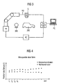
- Fig. 3 is a schematic representation of the embodiment of the present invention for measuring a measurement object 200.
- the embodiment of the present invention utilizes a robot R1 with a very high repeatability by a compensation of internal and / or external influences based on repeated measurement of the reference body 300. Then you just need once precisely determine the path of the sensor S.
- the web is deposited in a suitable form in a memory and retrieves it for later measurement of a measurement object 200 again from the memory for the processing of the measurement data of the sensor S, the sensor S is performed for each measurement object 200 along the same path.
- the web is suitably recorded in a representation in the world coordinate as well as in the robot coordinate of the robot R1, and this data pair as in FIG Fig. 4 saved as a curve.
- the robot controller RC can output at any time where the sensor S is located in the robot coordinate system.
- the sensor processing device PA queries the path of the robot controller RC for each measuring point of the sensor S and translates it into the world coordinate system by means of a previously determined table. This curve can consist of discrete points or represent a functional, which is obtained by a suitable interpolation of the measuring points.
- An indispensable prerequisite for the method according to the invention is that the web is precisely repeated.
- a compensation step is carried out regularly, in the case of this embodiment prior to the measurement of each further measurement object 200.
- the reference body 300 serves this purpose.
- the reference body 300 is measured regularly.
- the reference body 300 is constructed so that its dimensions do not change. If a different point cloud is obtained during a measurement of the reference body than in an original measurement, this is solely attributed to changes in the kinematics of the robot R1.
- the kinematics of the robot are subject to so-called internal influences, e.g. Wear of the joints, as well as external influences, such as Ambient temperature changes affecting the dimensions of the robot R1.
- the robot controller RC is adapted so that the sensor S is again guided along the original path and the original point cloud of the reference body results.
- the adaptation of the robot controller RC thus also compensates for the changes in the kinematics of the robot R1 to the path around the measurement object 200.
- Fig. 5 are shown schematically as a flowchart steps of the embodiment of the present invention for robotically measuring a measurement object 200.
- an initialization phase T1 to be explained, an actual path of the robot-guided sensor S is determined and stored. Thereafter, the calibration device K1, K2, KC for determining the paths of the sensor S can be dismantled T2 and used for other robots. Since this calibration device is very expensive, it is worth reusing it.
- the measurement phase T3, within which the kinematic compensation step is first executed, is performed that the sensor S is always guided along the same stored actual web. Then, a measurement object 200 is measured T5 and then a next measurement object 200 is provided for measurement T6.
- step T5 each point of the actual path is approached in a sequence, the world coordinates are loaded from the memory for each point A of the actual path and a measurement point of the measurement object is recorded at point A, so that the point cloud of the measurement object 200 is obtained ,
- Fig. 6 schematically the method for determining and setting the web is shown as a flow chart, which corresponds to an initialization phase T1.
- the path is transferred to the robot coordinate system T12. Fluctuations in the hand-held sensor S recorded during manual guidance can be reduced by smoothing the web in step T12. Otherwise, the robot-guided track should correspond to the recorded manual track, as far as the kinematics and the structure of the robot permit.
- the sensor S is guided robotically and the actual path is recorded T14. This robot-controlled actual lane is stored T15. Since the robot R1 has improved repeat accuracy, this actual path is now traced in subsequent guides of the sensor by means of the robot R1 in very good agreement.
- optical sensor such as a video camera.
- present invention is not limited thereto, it can be used in addition to optical and inductive or tactile sensors.
- the possibility of an absolute positionability of the robot is particularly advantageous.
Landscapes
- Engineering & Computer Science (AREA)
- Robotics (AREA)
- Mechanical Engineering (AREA)
- Physics & Mathematics (AREA)
- General Physics & Mathematics (AREA)
- Manipulator (AREA)
- Length Measuring Devices With Unspecified Measuring Means (AREA)
Claims (8)
- Procédé de mesure assistée par robot d'objets à mesurer (200), avec les étapes consistant à :a) spécifier les trajectoires d'un capteur (S) dans un système de coordonnées universelles, lesquelles sont nécessaires à la mesure d'un objet (200) ;b) transférer les trajectoires dans une représentation dans un système de coordonnées de robot d'un robot (R1) ;c) mettre à disposition un dispositif de calibrage externe (KC, K1, K2) ;d) déterminer les trajectoires réelles du capteur (S) guidé sur le robot (R1) dans un système de coordonnées universelles avec le dispositif de calibrage externe (KC, K1, K2) et enregistrer un tableau avec les trajectoires réelles et des trajectoires correspondantes ;e) mesurer, en étant assisté par robot, une pluralité d'autres objets à mesurer en utilisant le robot (R1) le long des trajectoires réelles, la position et l'orientation du capteur (S) dans les coordonnées de robot étant demandées à chaque point de mesure du capteur (S) et la position et l'orientation dans le système de coordonnées de robot étant transférées au moyen du tableau en coordonnées universelles ;f) après un nombre prédéterminé d'opérations de mesure, mesurer un corps de référence (300) avec le capteur (S) guidé avec le robot (R1) afin de compenser des influences externes et/ou internes pour augmenter la prévision de la reproductibilité et exécuter une adaptation d'une commande de robot (RC) à partir d'écarts entre un nuage de points mesuré et un nuage de points mesuré précédent du corps de référence (300) de telle façon à ce que les changements de la cinématique du robot (R1) qui conduisaient aux nuages de points différents ; soient compensés etles étapes a) à d) étant exécutées dans le cadre d'une phase d'initialisation et les étapes e) et f) étant exécutées plusieurs fois dans le cadre d'une phase de mesure et le dispositif de calibrage pouvant être éloigné après la fin de la phase d'initialisation.
- Procédé selon la revendication 1, selon lequel le nombre prédéterminé d'opérations de mesure de l'étape e) est égal à 1.
- Procédé selon les revendications 1 et 2, selon lequel la spécification des trajectoires du capteur (S) guidé sur le robot est obtenue par le dispositif de calibrage externe (KC, K1, K2).
- Procédé selon la revendication 3, selon lequel le dispositif de calibrage externe (KC, K1, K2) mesure les positions de repères (M) qui sont agencés de façon fixe ou amovible, apportés sur le capteur (S),
- Procédé selon la revendication 3 ou 4, selon lequel, pour spécifier les trajectoires du capteur (S), l'objet à mesurer (200) est mesuré en guidant le capteur (S) manuellement et en déterminant les trajectoires guidées manuellement du capteur (S) pendant la mesure avec le dispositif de calibrage externe.
- Procédé selon l'une des revendications précédentes, selon lequel, pour la spécification des trajectoires du capteur (S), le capteur (S) est guidé autour de l'objet à mesurer (200) soit à la main de manière découplée du robot (R1) soit par une commande manuelle du robot (R1).
- Procédé selon l'une des revendications précédentes, selon lequel, pour spécifier les trajectoires du capteur (S) guidé avec le robot (R) et/ou pour spécifier les trajectoires du capteur (S) autour du corps de référence (300), le capteur (S) est guidé autour du corps de référence (300) soit à la main de manière découplée du robot (R1) soit par une commande manuelle du robot (R1) et les trajectoires réelles sont enregistrées avec le dispositif de détermination de position externe (K1, K2, KC).
- Procédé selon l'une des revendications précédentes, selon lequel effectuée est l'adaptation des trajectoires réelles déterminées du capteur (S) aux trajectoires spécifiées du capteur (S).
Applications Claiming Priority (2)
| Application Number | Priority Date | Filing Date | Title |
|---|---|---|---|
| DE102004024378A DE102004024378B4 (de) | 2004-05-17 | 2004-05-17 | Verfahren zur robotergestützten Vermessung von Objekten |
| PCT/EP2005/004921 WO2005115700A1 (fr) | 2004-05-17 | 2005-05-06 | Procédé de mesure assistée par robot d'objets à mesurer |
Publications (2)
| Publication Number | Publication Date |
|---|---|
| EP1750909A1 EP1750909A1 (fr) | 2007-02-14 |
| EP1750909B1 true EP1750909B1 (fr) | 2009-07-22 |
Family
ID=34972334
Family Applications (1)
| Application Number | Title | Priority Date | Filing Date |
|---|---|---|---|
| EP05759568A Active EP1750909B1 (fr) | 2004-05-17 | 2005-05-06 | Procédé de mesure assistée par robot d'objets à mesurer |
Country Status (5)
| Country | Link |
|---|---|
| US (2) | US20090099690A1 (fr) |
| EP (1) | EP1750909B1 (fr) |
| CN (1) | CN100484725C (fr) |
| DE (2) | DE102004024378B4 (fr) |
| WO (1) | WO2005115700A1 (fr) |
Families Citing this family (20)
| Publication number | Priority date | Publication date | Assignee | Title |
|---|---|---|---|---|
| DE102007026956A1 (de) * | 2007-06-12 | 2008-12-18 | Kuka Innotec Gmbh | Verfahren und System zum Roboter geführten Depalettieren von Reifen |
| DE202008011332U1 (de) * | 2008-08-26 | 2010-02-11 | Dmg Microset Gmbh | Vorrichtung zum Vermessen und/oder Einstellen eines Werkzeugs |
| DE102008060052A1 (de) * | 2008-12-02 | 2010-06-17 | Kuka Roboter Gmbh | Verfahren und Vorrichtung zur Kompensation einer kinematischen Abweichung |
| DE102009041734B4 (de) | 2009-09-16 | 2023-11-02 | Kuka Roboter Gmbh | Vermessung eines Manipulators |
| WO2011140704A1 (fr) * | 2010-05-11 | 2011-11-17 | Abb Research Ltd. | Appareil, procédé, programme et support d'enregistrement pour un apprentissage hors ligne de robot |
| DE102010050138B4 (de) | 2010-11-03 | 2023-07-06 | Gienanth Gmbh | Vorrichtung zur Erzeugung einer Markierung an einem zu bearbeitenden Werkstück |
| KR101337650B1 (ko) * | 2011-11-02 | 2013-12-05 | 삼성중공업 주식회사 | 실시간 위빙 모션 제어 장치 및 그 방법 |
| CN105423919B (zh) * | 2015-12-18 | 2018-01-02 | 重庆德新机器人检测中心有限公司 | 利用固液相快速转换材料投影成像检测机器人精度的方法 |
| JP6430986B2 (ja) | 2016-03-25 | 2018-11-28 | ファナック株式会社 | ロボットを用いた位置決め装置 |
| JP6527178B2 (ja) | 2017-01-12 | 2019-06-05 | ファナック株式会社 | 視覚センサのキャリブレーション装置、方法及びプログラム |
| DE102017107593B4 (de) * | 2017-04-07 | 2023-04-27 | Deutsches Zentrum für Luft- und Raumfahrt e.V. | Verfahren zum Bestimmen unbekannter Transformationen |
| DE102017212261A1 (de) * | 2017-07-18 | 2019-01-24 | Bayerische Motoren Werke Aktiengesellschaft | Messsystem und Verfahren zum Einmessen mindestens eines automatischen, insbesondere mehrachsigen, Manipulators |
| CN108195354A (zh) * | 2017-12-21 | 2018-06-22 | 长沙长泰机器人有限公司 | 一种基于机器人的车辆定位方法和车辆定位系统 |
| EP3650740B1 (fr) * | 2018-11-06 | 2020-12-30 | Sick Ag | Système de sécurité et procédé de surveillance d'une machine |
| CN109490830B (zh) * | 2018-11-23 | 2024-08-02 | 北京天智航医疗科技股份有限公司 | 手术机器人定位系统精度检测方法及检测装置 |
| US11911914B2 (en) * | 2019-01-28 | 2024-02-27 | Cognex Corporation | System and method for automatic hand-eye calibration of vision system for robot motion |
| DE102019102927B4 (de) | 2019-02-06 | 2023-02-23 | Carl Zeiss Industrielle Messtechnik Gmbh | Verfahren und Vorrichtung zum Bestimmen von dimensionalen und/oder geometrischen Eigenschaften eines Messobjekts |
| US20220176564A1 (en) | 2020-12-04 | 2022-06-09 | GM Global Technology Operations LLC | Accurate position control for fixtureless assembly |
| DE102022118260B3 (de) | 2022-07-21 | 2023-10-05 | Dürr Assembly Products GmbH | Verfahren zur Kalibrierung und/oder Justierung des intrinsischen Koordinatensystems eines Fahrzeugaggregats relativ zu einem Koordinatensystem des Fahrzeugs und Fahrzeugprüfstand zur Durchführung des Verfahrens |
| DE102023101972A1 (de) | 2023-01-27 | 2024-08-01 | Matthias Krebs | Sensorsystem und Verfahren zum Betrieb eines Sensorsystems |
Family Cites Families (16)
| Publication number | Priority date | Publication date | Assignee | Title |
|---|---|---|---|---|
| US4788440A (en) * | 1981-05-11 | 1988-11-29 | Diffracto Ltd. | Electro-optical systems for control of robots, manipulator arms and coordinate measuring machines |
| US4753569A (en) * | 1982-12-28 | 1988-06-28 | Diffracto, Ltd. | Robot calibration |
| US4754415A (en) * | 1984-10-12 | 1988-06-28 | Diffracto Ltd. | Robotic alignment and part simulation |
| EP0312119A3 (fr) * | 1987-10-16 | 1989-05-31 | Nissan Motor Co., Ltd. | Robot de mesure tridimensionnel |
| US5380978A (en) * | 1991-07-12 | 1995-01-10 | Pryor; Timothy R. | Method and apparatus for assembly of car bodies and other 3-dimensional objects |
| WO1997024206A1 (fr) * | 1995-12-27 | 1997-07-10 | Fanuc Ltd | Systeme robotique composite de detection |
| DE19626459C2 (de) * | 1996-07-02 | 1999-09-02 | Kuka Schweissanlagen Gmbh | Verfahren und Vorrichtung zum Teachen eines programmgesteuerten Roboters |
| JP2001515236A (ja) * | 1997-09-04 | 2001-09-18 | ダイナログ インコーポレイテッド | ロボット検査システムを較正するための方法 |
| DE19826395A1 (de) * | 1998-06-12 | 1999-12-23 | Amatec Gmbh | Verfahren zum Erfassen und Kompensieren von kinematischen Veränderungen eines Roboters |
| DE19931676C2 (de) * | 1999-07-08 | 2002-07-11 | Kuka Schweissanlagen Gmbh | Verfahren zum Vermessen von Werkstücken und Bearbeitungsstation |
| EP1189732B1 (fr) * | 1999-06-26 | 2003-05-07 | KUKA Schweissanlagen GmbH | Procede et dispositif d'etalonnage de stations de mesures robotisees, de manipulateurs, et de systemes de mesure optiques associes |
| US6166811A (en) * | 1999-08-12 | 2000-12-26 | Perceptron, Inc. | Robot-based gauging system for determining three-dimensional measurement data |
| US6374158B1 (en) * | 2000-02-15 | 2002-04-16 | General Electric Company | Robotic laser pointer |
| DE10048952B4 (de) * | 2000-10-04 | 2008-08-21 | Kuka Roboter Gmbh | Verfahren und Vorrichtung zur Aufnahme unbekannter Raumpunkte in einer Arbeitszelle eines Roboters |
| CA2369845A1 (fr) * | 2002-01-31 | 2003-07-31 | Braintech, Inc. | Methode et appareil pour robotique guidee a vision 3d a camera simple |
| ATE531488T1 (de) * | 2002-03-04 | 2011-11-15 | Vmt Vision Machine Technic Bildverarbeitungssysteme Gmbh | Verfahren zur bestimmung der lage eines objektes und eines werkstücks im raum zur automatischen montage des werkstücks am objekt |
-
2004
- 2004-05-17 DE DE102004024378A patent/DE102004024378B4/de not_active Expired - Lifetime
-
2005
- 2005-05-06 US US11/720,982 patent/US20090099690A1/en not_active Abandoned
- 2005-05-06 EP EP05759568A patent/EP1750909B1/fr active Active
- 2005-05-06 DE DE502005007752T patent/DE502005007752D1/de active Active
- 2005-05-06 WO PCT/EP2005/004921 patent/WO2005115700A1/fr active Application Filing
- 2005-05-06 CN CNB2005800157100A patent/CN100484725C/zh active Active
-
2015
- 2015-11-24 US US14/950,699 patent/US9833904B2/en active Active
Also Published As
| Publication number | Publication date |
|---|---|
| DE102004024378B4 (de) | 2009-05-20 |
| US20160075029A1 (en) | 2016-03-17 |
| CN100484725C (zh) | 2009-05-06 |
| WO2005115700B1 (fr) | 2006-01-19 |
| US20090099690A1 (en) | 2009-04-16 |
| DE102004024378A1 (de) | 2005-12-15 |
| DE502005007752D1 (de) | 2009-09-03 |
| EP1750909A1 (fr) | 2007-02-14 |
| US9833904B2 (en) | 2017-12-05 |
| WO2005115700A1 (fr) | 2005-12-08 |
| CN1953848A (zh) | 2007-04-25 |
Similar Documents
| Publication | Publication Date | Title |
|---|---|---|
| EP1750909B1 (fr) | Procédé de mesure assistée par robot d'objets à mesurer | |
| DE102018001026B4 (de) | Robotersystem mit einer lernenden Steuerungsfunktion und lernendes Steuerungsverfahren | |
| DE102009034529B4 (de) | Automatisches Führungs- und Erkennungssystem sowie Verfahren für dieses | |
| DE19930087B4 (de) | Verfahren und Vorrichtung zur Regelung der Vorhalteposition eines Manipulators eines Handhabungsgeräts | |
| EP0963816B1 (fr) | Méthode de mesure et de compensation des altérations cinématiques d'un robot | |
| DE102017111543B4 (de) | Robotersteuerungsvorrichtung und ein Verfahren zur Steuerung eines Roboters | |
| DE102014017307B4 (de) | Verfahren und System zum Bearbeiten eines Bauteils mit einem robotergeführten Werkzeug | |
| DE10242710A1 (de) | Verfahren zum Herstellen eines Verbindungsbereiches auf einem Werkstück | |
| DE102019131284B4 (de) | Robotersystem und Koordinatenumwandlungsverfahren | |
| DE102015109557B4 (de) | Verfahren zur Einstellung einer Prüf- oder Messposition eines berührungslos wirkenden Sensors | |
| DE102017003993B4 (de) | Kalibrierung eines Roboters | |
| EP3953113A1 (fr) | Procédé de revêtement et système de revêtement afférent | |
| EP1172183A2 (fr) | Dispositif et appareil de génération de données de déplacement corrigées pour un déplacement prédéfini d'un dispositif mobile, dispositif mobile et système composé de dispositifs mobiles | |
| DE10349361A1 (de) | Verfahren und Vorrichtung zum Positionieren eines Handhabungsgeräts | |
| EP0256968A1 (fr) | Procédé automatique de mesure sans contact en trois dimensions d'objets de grande extension | |
| DE112021001173T5 (de) | Entgratungsvorrichtung und Steuerungssystem | |
| DE112018003597T5 (de) | Greifsystem | |
| EP1120204A2 (fr) | Méthode de calibrage d'un robot industriel | |
| DE102015200319A1 (de) | Einmessverfahren aus Kombination von Vorpositionierung und Handführen | |
| EP3465076B1 (fr) | Dispositif de mesure d'objets | |
| DE102017004433B4 (de) | Roboterjustage | |
| DE102019131401B3 (de) | Kalibrierung einer Impedanzregelung eines Robotermanipulators | |
| DE102017107593B4 (de) | Verfahren zum Bestimmen unbekannter Transformationen | |
| DE202019104426U1 (de) | Bearbeitung eines Werkstücks durch einen Robotermanipulator mittels CAD-Modell | |
| DE102009034938B4 (de) | Verfahren zur Kommandierung eines Bewegungssystems mit einer Messeinrichtung |
Legal Events
| Date | Code | Title | Description |
|---|---|---|---|
| PUAI | Public reference made under article 153(3) epc to a published international application that has entered the european phase |
Free format text: ORIGINAL CODE: 0009012 |
|
| 17P | Request for examination filed |
Effective date: 20061018 |
|
| AK | Designated contracting states |
Kind code of ref document: A1 Designated state(s): AT BE BG CH CY CZ DE DK EE ES FI FR GB GR HU IE IS IT LI LT LU MC NL PL PT RO SE SI SK TR |
|
| RIN1 | Information on inventor provided before grant (corrected) |
Inventor name: VERL, ALEXANDER |
|
| DAX | Request for extension of the european patent (deleted) | ||
| RIN1 | Information on inventor provided before grant (corrected) |
Inventor name: VERL, ALEXANDER |
|
| GRAP | Despatch of communication of intention to grant a patent |
Free format text: ORIGINAL CODE: EPIDOSNIGR1 |
|
| GRAS | Grant fee paid |
Free format text: ORIGINAL CODE: EPIDOSNIGR3 |
|
| GRAA | (expected) grant |
Free format text: ORIGINAL CODE: 0009210 |
|
| AK | Designated contracting states |
Kind code of ref document: B1 Designated state(s): AT BE BG CH CY CZ DE DK EE ES FI FR GB GR HU IE IS IT LI LT LU MC NL PL PT RO SE SI SK TR |
|
| REG | Reference to a national code |
Ref country code: GB Ref legal event code: FG4D Free format text: NOT ENGLISH |
|
| REG | Reference to a national code |
Ref country code: CH Ref legal event code: EP |
|
| REG | Reference to a national code |
Ref country code: IE Ref legal event code: FG4D |
|
| REF | Corresponds to: |
Ref document number: 502005007752 Country of ref document: DE Date of ref document: 20090903 Kind code of ref document: P |
|
| NLV1 | Nl: lapsed or annulled due to failure to fulfill the requirements of art. 29p and 29m of the patents act | ||
| PG25 | Lapsed in a contracting state [announced via postgrant information from national office to epo] |
Ref country code: SE Free format text: LAPSE BECAUSE OF FAILURE TO SUBMIT A TRANSLATION OF THE DESCRIPTION OR TO PAY THE FEE WITHIN THE PRESCRIBED TIME-LIMIT Effective date: 20090722 Ref country code: IS Free format text: LAPSE BECAUSE OF FAILURE TO SUBMIT A TRANSLATION OF THE DESCRIPTION OR TO PAY THE FEE WITHIN THE PRESCRIBED TIME-LIMIT Effective date: 20091122 Ref country code: ES Free format text: LAPSE BECAUSE OF FAILURE TO SUBMIT A TRANSLATION OF THE DESCRIPTION OR TO PAY THE FEE WITHIN THE PRESCRIBED TIME-LIMIT Effective date: 20091102 Ref country code: LT Free format text: LAPSE BECAUSE OF FAILURE TO SUBMIT A TRANSLATION OF THE DESCRIPTION OR TO PAY THE FEE WITHIN THE PRESCRIBED TIME-LIMIT Effective date: 20090722 Ref country code: FI Free format text: LAPSE BECAUSE OF FAILURE TO SUBMIT A TRANSLATION OF THE DESCRIPTION OR TO PAY THE FEE WITHIN THE PRESCRIBED TIME-LIMIT Effective date: 20090722 |
|
| PG25 | Lapsed in a contracting state [announced via postgrant information from national office to epo] |
Ref country code: SI Free format text: LAPSE BECAUSE OF FAILURE TO SUBMIT A TRANSLATION OF THE DESCRIPTION OR TO PAY THE FEE WITHIN THE PRESCRIBED TIME-LIMIT Effective date: 20090722 Ref country code: PL Free format text: LAPSE BECAUSE OF FAILURE TO SUBMIT A TRANSLATION OF THE DESCRIPTION OR TO PAY THE FEE WITHIN THE PRESCRIBED TIME-LIMIT Effective date: 20090722 Ref country code: NL Free format text: LAPSE BECAUSE OF FAILURE TO SUBMIT A TRANSLATION OF THE DESCRIPTION OR TO PAY THE FEE WITHIN THE PRESCRIBED TIME-LIMIT Effective date: 20090722 |
|
| REG | Reference to a national code |
Ref country code: IE Ref legal event code: FD4D |
|
| PG25 | Lapsed in a contracting state [announced via postgrant information from national office to epo] |
Ref country code: PT Free format text: LAPSE BECAUSE OF FAILURE TO SUBMIT A TRANSLATION OF THE DESCRIPTION OR TO PAY THE FEE WITHIN THE PRESCRIBED TIME-LIMIT Effective date: 20091122 Ref country code: BG Free format text: LAPSE BECAUSE OF FAILURE TO SUBMIT A TRANSLATION OF THE DESCRIPTION OR TO PAY THE FEE WITHIN THE PRESCRIBED TIME-LIMIT Effective date: 20091022 |
|
| PG25 | Lapsed in a contracting state [announced via postgrant information from national office to epo] |
Ref country code: CZ Free format text: LAPSE BECAUSE OF FAILURE TO SUBMIT A TRANSLATION OF THE DESCRIPTION OR TO PAY THE FEE WITHIN THE PRESCRIBED TIME-LIMIT Effective date: 20090722 Ref country code: IE Free format text: LAPSE BECAUSE OF FAILURE TO SUBMIT A TRANSLATION OF THE DESCRIPTION OR TO PAY THE FEE WITHIN THE PRESCRIBED TIME-LIMIT Effective date: 20090722 Ref country code: EE Free format text: LAPSE BECAUSE OF FAILURE TO SUBMIT A TRANSLATION OF THE DESCRIPTION OR TO PAY THE FEE WITHIN THE PRESCRIBED TIME-LIMIT Effective date: 20090722 Ref country code: RO Free format text: LAPSE BECAUSE OF FAILURE TO SUBMIT A TRANSLATION OF THE DESCRIPTION OR TO PAY THE FEE WITHIN THE PRESCRIBED TIME-LIMIT Effective date: 20090722 Ref country code: DK Free format text: LAPSE BECAUSE OF FAILURE TO SUBMIT A TRANSLATION OF THE DESCRIPTION OR TO PAY THE FEE WITHIN THE PRESCRIBED TIME-LIMIT Effective date: 20090722 |
|
| PLBE | No opposition filed within time limit |
Free format text: ORIGINAL CODE: 0009261 |
|
| STAA | Information on the status of an ep patent application or granted ep patent |
Free format text: STATUS: NO OPPOSITION FILED WITHIN TIME LIMIT |
|
| PG25 | Lapsed in a contracting state [announced via postgrant information from national office to epo] |
Ref country code: SK Free format text: LAPSE BECAUSE OF FAILURE TO SUBMIT A TRANSLATION OF THE DESCRIPTION OR TO PAY THE FEE WITHIN THE PRESCRIBED TIME-LIMIT Effective date: 20090722 |
|
| 26N | No opposition filed |
Effective date: 20100423 |
|
| PG25 | Lapsed in a contracting state [announced via postgrant information from national office to epo] |
Ref country code: GR Free format text: LAPSE BECAUSE OF FAILURE TO SUBMIT A TRANSLATION OF THE DESCRIPTION OR TO PAY THE FEE WITHIN THE PRESCRIBED TIME-LIMIT Effective date: 20091023 |
|
| BERE | Be: lapsed |
Owner name: KUKA ROBOTER G.M.B.H. Effective date: 20100531 |
|
| PG25 | Lapsed in a contracting state [announced via postgrant information from national office to epo] |
Ref country code: MC Free format text: LAPSE BECAUSE OF NON-PAYMENT OF DUE FEES Effective date: 20100531 |
|
| REG | Reference to a national code |
Ref country code: CH Ref legal event code: PL |
|
| GBPC | Gb: european patent ceased through non-payment of renewal fee |
Effective date: 20100506 |
|
| PG25 | Lapsed in a contracting state [announced via postgrant information from national office to epo] |
Ref country code: CH Free format text: LAPSE BECAUSE OF NON-PAYMENT OF DUE FEES Effective date: 20100531 Ref country code: LI Free format text: LAPSE BECAUSE OF NON-PAYMENT OF DUE FEES Effective date: 20100531 |
|
| PG25 | Lapsed in a contracting state [announced via postgrant information from national office to epo] |
Ref country code: BE Free format text: LAPSE BECAUSE OF NON-PAYMENT OF DUE FEES Effective date: 20100531 |
|
| PG25 | Lapsed in a contracting state [announced via postgrant information from national office to epo] |
Ref country code: GB Free format text: LAPSE BECAUSE OF NON-PAYMENT OF DUE FEES Effective date: 20100506 |
|
| PG25 | Lapsed in a contracting state [announced via postgrant information from national office to epo] |
Ref country code: AT Free format text: LAPSE BECAUSE OF NON-PAYMENT OF DUE FEES Effective date: 20100506 |
|
| PG25 | Lapsed in a contracting state [announced via postgrant information from national office to epo] |
Ref country code: CY Free format text: LAPSE BECAUSE OF FAILURE TO SUBMIT A TRANSLATION OF THE DESCRIPTION OR TO PAY THE FEE WITHIN THE PRESCRIBED TIME-LIMIT Effective date: 20090722 |
|
| PG25 | Lapsed in a contracting state [announced via postgrant information from national office to epo] |
Ref country code: HU Free format text: LAPSE BECAUSE OF FAILURE TO SUBMIT A TRANSLATION OF THE DESCRIPTION OR TO PAY THE FEE WITHIN THE PRESCRIBED TIME-LIMIT Effective date: 20100123 Ref country code: LU Free format text: LAPSE BECAUSE OF NON-PAYMENT OF DUE FEES Effective date: 20100506 |
|
| PG25 | Lapsed in a contracting state [announced via postgrant information from national office to epo] |
Ref country code: TR Free format text: LAPSE BECAUSE OF FAILURE TO SUBMIT A TRANSLATION OF THE DESCRIPTION OR TO PAY THE FEE WITHIN THE PRESCRIBED TIME-LIMIT Effective date: 20090722 |
|
| REG | Reference to a national code |
Ref country code: FR Ref legal event code: PLFP Year of fee payment: 12 |
|
| REG | Reference to a national code |
Ref country code: FR Ref legal event code: PLFP Year of fee payment: 13 |
|
| REG | Reference to a national code |
Ref country code: FR Ref legal event code: PLFP Year of fee payment: 14 |
|
| REG | Reference to a national code |
Ref country code: DE Ref legal event code: R082 Ref document number: 502005007752 Country of ref document: DE Representative=s name: ISARPATENT - PATENT- UND RECHTSANWAELTE BEHNIS, DE Ref country code: DE Ref legal event code: R082 Ref document number: 502005007752 Country of ref document: DE Representative=s name: ISARPATENT - PATENT- UND RECHTSANWAELTE BARTH , DE Ref country code: DE Ref legal event code: R082 Ref document number: 502005007752 Country of ref document: DE Representative=s name: ISARPATENT - PATENTANWAELTE- UND RECHTSANWAELT, DE Ref country code: DE Ref legal event code: R081 Ref document number: 502005007752 Country of ref document: DE Owner name: KUKA DEUTSCHLAND GMBH, DE Free format text: FORMER OWNER: KUKA ROBOTER GMBH, 86165 AUGSBURG, DE |
|
| PGFP | Annual fee paid to national office [announced via postgrant information from national office to epo] |
Ref country code: FR Payment date: 20230309 Year of fee payment: 19 |
|
| P01 | Opt-out of the competence of the unified patent court (upc) registered |
Effective date: 20230528 |
|
| PGFP | Annual fee paid to national office [announced via postgrant information from national office to epo] |
Ref country code: IT Payment date: 20230412 Year of fee payment: 19 Ref country code: DE Payment date: 20230516 Year of fee payment: 19 |