EP3951306A1 - High-performance electronics cooling system - Google Patents
High-performance electronics cooling system Download PDFInfo
- Publication number
- EP3951306A1 EP3951306A1 EP21197460.5A EP21197460A EP3951306A1 EP 3951306 A1 EP3951306 A1 EP 3951306A1 EP 21197460 A EP21197460 A EP 21197460A EP 3951306 A1 EP3951306 A1 EP 3951306A1
- Authority
- EP
- European Patent Office
- Prior art keywords
- cooling system
- heat transfer
- transfer plate
- wick
- condensing
- Prior art date
- Legal status (The legal status is an assumption and is not a legal conclusion. Google has not performed a legal analysis and makes no representation as to the accuracy of the status listed.)
- Granted
Links
Images




Classifications
-
- H—ELECTRICITY
- H05—ELECTRIC TECHNIQUES NOT OTHERWISE PROVIDED FOR
- H05K—PRINTED CIRCUITS; CASINGS OR CONSTRUCTIONAL DETAILS OF ELECTRIC APPARATUS; MANUFACTURE OF ASSEMBLAGES OF ELECTRICAL COMPONENTS
- H05K7/00—Constructional details common to different types of electric apparatus
- H05K7/20—Modifications to facilitate cooling, ventilating, or heating
- H05K7/2029—Modifications to facilitate cooling, ventilating, or heating using a liquid coolant with phase change in electronic enclosures
- H05K7/20336—Heat pipes, e.g. wicks or capillary pumps
-
- F—MECHANICAL ENGINEERING; LIGHTING; HEATING; WEAPONS; BLASTING
- F28—HEAT EXCHANGE IN GENERAL
- F28D—HEAT-EXCHANGE APPARATUS, NOT PROVIDED FOR IN ANOTHER SUBCLASS, IN WHICH THE HEAT-EXCHANGE MEDIA DO NOT COME INTO DIRECT CONTACT
- F28D15/00—Heat-exchange apparatus with the intermediate heat-transfer medium in closed tubes passing into or through the conduit walls ; Heat-exchange apparatus employing intermediate heat-transfer medium or bodies
- F28D15/02—Heat-exchange apparatus with the intermediate heat-transfer medium in closed tubes passing into or through the conduit walls ; Heat-exchange apparatus employing intermediate heat-transfer medium or bodies in which the medium condenses and evaporates, e.g. heat pipes
- F28D15/04—Heat-exchange apparatus with the intermediate heat-transfer medium in closed tubes passing into or through the conduit walls ; Heat-exchange apparatus employing intermediate heat-transfer medium or bodies in which the medium condenses and evaporates, e.g. heat pipes with tubes having a capillary structure
- F28D15/046—Heat-exchange apparatus with the intermediate heat-transfer medium in closed tubes passing into or through the conduit walls ; Heat-exchange apparatus employing intermediate heat-transfer medium or bodies in which the medium condenses and evaporates, e.g. heat pipes with tubes having a capillary structure characterised by the material or the construction of the capillary structure
-
- F—MECHANICAL ENGINEERING; LIGHTING; HEATING; WEAPONS; BLASTING
- F28—HEAT EXCHANGE IN GENERAL
- F28D—HEAT-EXCHANGE APPARATUS, NOT PROVIDED FOR IN ANOTHER SUBCLASS, IN WHICH THE HEAT-EXCHANGE MEDIA DO NOT COME INTO DIRECT CONTACT
- F28D15/00—Heat-exchange apparatus with the intermediate heat-transfer medium in closed tubes passing into or through the conduit walls ; Heat-exchange apparatus employing intermediate heat-transfer medium or bodies
- F28D15/02—Heat-exchange apparatus with the intermediate heat-transfer medium in closed tubes passing into or through the conduit walls ; Heat-exchange apparatus employing intermediate heat-transfer medium or bodies in which the medium condenses and evaporates, e.g. heat pipes
- F28D15/04—Heat-exchange apparatus with the intermediate heat-transfer medium in closed tubes passing into or through the conduit walls ; Heat-exchange apparatus employing intermediate heat-transfer medium or bodies in which the medium condenses and evaporates, e.g. heat pipes with tubes having a capillary structure
-
- H—ELECTRICITY
- H10—SEMICONDUCTOR DEVICES; ELECTRIC SOLID-STATE DEVICES NOT OTHERWISE PROVIDED FOR
- H10W—GENERIC PACKAGES, INTERCONNECTIONS, CONNECTORS OR OTHER CONSTRUCTIONAL DETAILS OF DEVICES COVERED BY CLASS H10
- H10W40/00—Arrangements for thermal protection or thermal control
- H10W40/70—Fillings or auxiliary members in containers or in encapsulations for thermal protection or control
- H10W40/73—Fillings or auxiliary members in containers or in encapsulations for thermal protection or control for cooling by change of state
-
- F—MECHANICAL ENGINEERING; LIGHTING; HEATING; WEAPONS; BLASTING
- F28—HEAT EXCHANGE IN GENERAL
- F28F—DETAILS OF HEAT-EXCHANGE AND HEAT-TRANSFER APPARATUS, OF GENERAL APPLICATION
- F28F2215/00—Fins
- F28F2215/06—Hollow fins; fins with internal circuits
-
- F—MECHANICAL ENGINEERING; LIGHTING; HEATING; WEAPONS; BLASTING
- F28—HEAT EXCHANGE IN GENERAL
- F28F—DETAILS OF HEAT-EXCHANGE AND HEAT-TRANSFER APPARATUS, OF GENERAL APPLICATION
- F28F2240/00—Spacing means
Definitions
- Cooling systems are traditionally used to dissipate heat generated by electronic circuit packages, such as an integrated circuit die package. Heat pipes and vapor chambers are components of such cooling systems. In addition, liquid cooling solutions are also used to transfer heat generated by such electronic circuit packages (ECPs). As ECP manufacturers develop advanced microprocessors for high-performance processing and computing applications, new advances in ECP cooling solutions are needed to adequately manage the increased heat that is generated by these more advanced components.
- the disclosure relates to a cooling system for an electronic circuit package.
- the cooling system includes a heat transfer plate positioned in thermal contact with an electronic circuit package surface.
- the heat transfer plate forms a bottom surface of an evaporative region of the cooling system.
- the cooling system further includes a plurality of condensing tubes in fluid communication with, and extending away from, the evaporative region.
- the evaporative region and condensing tubes together form a single, uninterrupted, sealed enclosure.
- the cooling system further includes a fluid disposed within the sealed disclosure.
- the cooling system further includes a plurality of spacers substantially filling gaps between the heat transfer plate and respective condensing tubes. Each of the spacers is configured as an independent component to allow the passage of fluid through an interior space of each spacer.
- the cooling system further includes a plurality of wicks. Each wick is positioned partially within a corresponding spacer to which the spacer is fluidically coupled.
- each wick contacts the heat transfer plate.
- the portion of each wick in contact with the heat transfer plate is oriented substantially parallel to the heat transfer plate.
- the portion of each wick in contact with the heat transfer plate covers less than three-quarters of a cross sectional area of an end of a corresponding spacer.
- the portion of each wick in contact with the heat transfer plate substantially covers an end of its corresponding spacer and extends in a direction parallel to the heat transfer plate beyond an edge of the corresponding spacer.
- each wick comprises a metal mesh.
- each spacer extends at least partially into a corresponding condensing tube.
- an inner surface of each condensing tube defines a plurality of grooves.
- the heat transfer plate comprises a plurality of fins extending away from the heat transfer plate within the sealed enclosure.
- the plurality of fins are arranged in an irregular fashion.
- the plurality of fins are arranged based on a variation in heat generation across the electronic circuit package surface in thermal contact with the heat transfer plate.
- at least a portion of the sealed enclosure is coated with a copper powder.
- the copper powder coating the sealed enclosure has a particle size of about 0.1 mm.
- the copper powder coating the sealed enclosure forms a coating having a thickness of about 0.3 mm.
- the copper powder coating coats a plurality of fins extending away from the heat transfer plate within the sealed enclosure. In some implementations, the copper powder coating coats at least one of the heat transfer plate and a surface of the evaporative region opposite the heat transfer plate within the sealed enclosure. In some implementations, the interiors of the condensing tubes are free from the copper powder coating. In some implementations, a diameter of each spacer flares outward proximate to the heat transfer plate. In some implementations, a portion of each spacer extends closer to the cooling plate than a remainder of the spacer. In some implementations, the condensing tubes are positioned about a perimeter of the sealed enclosure.
- the disclosure relates to a cooling system for an electronic circuit package.
- the cooling system includes a heat transfer plate positioned in thermal contact with an electronic circuit package surface.
- the heat transfer plate forms a bottom surface of an evaporative region of the cooling system.
- the cooling system further includes a plurality of condensing tubes in fluid communication with, and extending away from, the evaporative region.
- the evaporative region and condensing tubes together form a single, uninterrupted, sealed enclosure.
- Each of the plurality of condensing tubes includes a plurality of grooves.
- the cooling system further includes a fluid disposed within the sealed disclosure.
- the cooling system includes a plurality of wicks.
- Each wick is positioned such that one end is in contact with the heat transfer plate and an opposite end extends into a proximal end of a corresponding condensing tube for a distance that is less than 5% of the length of the corresponding condensing tube.
- each wick comprises a multi-layer copper mesh.
- Heat dissipation is a major concern for manufacturers of electronic circuit packages, such as an integrated circuit die package.
- ECPs electronic circuit packages
- the need for improved cooling solutions also increases in order for users to gain the full benefit of these high-performance electronic circuit designs without being hindered by performance degradations due to sub-optimal management of heat that is generated by the more powerful ECP.
- Heat pipes and vapor chambers have often been used in this domain to cool ECPs.
- the cooling performance declines because the solutions are unable to dissipate enough heat at a fast enough rate to ensure optimal performance of the ECP.
- cooling capacity of a particular heat pipe or vapor chamber design does not match the heat generation profile of a given ECP for which the cooling solution has been applied.
- temperatures in the ECP rise which can degrade ECP performance and/or negatively impact the life-span and reliability of the ECP.
- Cooling solutions that include liquid cooling methods are available but often involve increased cost and design complexity.
- the cooling systems disclosed herein can avoid the expensive design, manufacturing, and maintenance requirements that are typically associated with liquid cooling solutions.
- the disclosed cooling systems are also well-suited for deployment with high-power components (e.g., processors performing computationally intensive operations, such as machine learning applications) and may enable use of higher processor speeds to increase chip performance.
- the disclosed cooling systems include a number of features to improve heat transfer away from an ECP to which the cooling system is attached. These features, alone and/or in combination, can help enable the evaporation process to be improved, and in some cases optimized, for a particular heat source, resulting in more efficient and consistent heat transfer away from high power density ECPs.
- the disclosed cooling systems may include a single continuous liquid-vapor chamber.
- the chamber may include an evaporator plate, which is in contact with the ECP and transfers heat into a liquid coolant that is included in the chamber. The liquid coolant may then evaporate as heat is absorbed from the ECP and the moisture vapor generated from the evaporating liquid may accumulate in the condensing tubes.
- the heat contained in the moisture vapor may be transferred to the condensing tube walls and consequently to an external cooling medium (which may include water or air, or other fluids).
- the liquid condensate that accumulates on the inner surface of the condensing tube walls may then flow back to the evaporative region from the condensing tubes.
- the cooling system can include independent structures, referred to herein as spacers that fluidically couple the condensing tubes to the evaporative region.
- spacers may include a rigid component and/or a wick, to provide a continuous flow of liquid coolant for more efficient heat transfer.
- the spacer may act as a "bridge" between the end of the condensing tubes closest to the evaporator plate (referred to as the "proximal end") and the heat transfer plate of the evaporative portion of the chamber.
- the wicks may provide a wicking effect, drawing the condensate liquid from the condensing tubes back down into the evaporative portion of the chamber, rather than allowing the liquid to accumulate in the proximal end of the condensing tubes and drip down into the evaporator plate.
- the inner walls of the evaporative portion of the chamber may include surface coatings to improve evaporation efficiency.
- a copper powder may coat the heat transfer plate and the surfaces of the chamber that are opposite the heat transfer plate.
- the surface coating may also coat the walls of the chamber and/or the inner walls of the condensing tubes.
- the inner walls of the condensing tubes lack a surface coating, and instead include a series of longitudinal grooves that extend the length of the condensing tubes.
- the wick may include a multi-layer copper mesh extending between the condensing tubes and the heat transfer plate.
- fins may also be added to the internal surface of the heat transfer plate to increase the surface area of the heat transfer plate. The fins may also be coated with a copper coating to boost the evaporative efficiency of the cooling system.
- the heat transfer plate may be attached to an upper portion of the chamber to form an enclosed, single-volume, continuous liquid-vapor cooling system.
- the condensing tubes may be connected to the sides of this enclosed chamber or to the top (or a combination of both connection configurations).
- the condensing tubes may include a wick to provide a capillary effect and improve fluid circulation between the evaporative and condensing regions of the chamber.
- the condensing tubes may include grooves to reduce the friction of the condensate on the condensing tube inner walls and may facilitate movement of the condensate back to the evaporative region.
- the disclosed cooling system architecture enhances the air cooling capacity of the condensing tubes and addresses the problem of managing high heat flux that is typically generated by high power ASICs or microprocessors.
- the configuration of high power processors included in an ECP can greatly affect the heat transfer performance of the cooling system used to cool the ECP.
- a solution to this problem may include a cooling system that is optimized for the configuration or layout of the high-performance components that are included in a particular ECP configuration.
- an ECP configuration may be arranged such that numerous microprocessors are positioned around the perimeter of the ECP.
- a cooling system that includes design elements in the center of the ECP may not demonstrate the same heat transfer capabilities as a cooling system configured with heat transfer features that are similarly mapped or positioned in relation to the heat generating components of the ECP, such as cooling system features that are configured around the perimeter of the cooling system in positions corresponding to the heat generating processors of the ECP.
- One way the disclosed cooling systems disclosed herein address this problem is by enabling an ECP manufacturer to customize the shape, elevation and density of a plurality of fins that may be arranged on the heat transfer plate that is coupled to the ECP.
- the fins may be arranged in a uniform pattern or an irregular pattern that is designed to optimize the heat transfer away from the heat generating portions of the ECP over which the fins are located.
- regions of the ECP with a greater density of heat-generating ASICs or microprocessors may be mapped and a heat transfer plate may be manufactured with a plurality of fins whose location, density and coating properties may be optimized to efficiently manage the heat generated by the microprocessors.
- regions of the heat transfer plate located above components of an ECP that generate greater amounts of heat may be include a greater number of fins, a greater fin surface area, or a greater fin density (and thus greater heat transfer capacity) than regions of the heat transfer plate located above lower-powered integrated circuits in the ECP over which the heat transfer plate is located.
- FIG. 1 is a diagram of an example electronic circuit package cooling system 105.
- the cooling system 105 is coupled to an electronic circuit package (ECP) 110, such as an integrated circuit die package.
- ECP electronic circuit package
- the ECP 110 may further include one or more microprocessors, such as ASICs, field programmable gate arrays (FPGAs), or microprocessors.
- the cooling system 105 also includes a heat transfer plate 115.
- the cooling system includes an evaporative region 120 and a plurality of condensing regions 125.
- the cooling system 105 includes a plurality of condensing tubes 130 and a plurality of spacers 135.
- the cooling system 105 also includes a plurality of wicks 140.
- the cooling system 105 is formed as a single, uninterrupted, sealed enclosure or chamber.
- the cooling system 105 includes a heat transfer plate 105 forming the bottom or lower portion of the chamber and a plurality of condensing tubes 130 forming an upper portion of the chamber.
- the cooling system 105 includes an evaporative region 120 and a plurality of condensing regions 125, located within the condensing tubes 130.
- the upper portion of the chamber may be fitted as a lid to the lower portion of the chamber to create the single, continuous volume chamber.
- the chamber may include a liquid (e.g., water or a coolant fluid) to absorb the heat that is generated by the ECP 110.
- the generated heat is absorbed by the liquid within the evaporative region 120 and transferred to the condensing region 125 as the liquid evaporates.
- the evaporated liquid is transferred to the condensing tubes 130 as vapor where, as the vapor condenses on the walls of the condensing tubes 130, the heat is dissipated through the walls of the condensing tubes 130 into an external cooling medium surrounding the condensing tubes 130, such as air or water or another fluid.
- the condensate may then flow from the walls of the condensing tubes 130 back to the evaporative region 120.
- the design of the single, continuous volume liquid-vapor chamber of the cooling system 105 may provide the benefit of allowing all the condensing tubes 130 to operate at the same temperature (assuming equal vapor pressure inside).
- the condensing tubes 130 when connected to the same chamber or volume of space (e.g., the evaporative region 120) and exposed to the lower temperature liquid present in the evaporative region 120, may transfer a higher heat load than if the condensing tubes 130 were not connected to the same chamber or volume of space or were otherwise located downstream of the liquid coolant.
- a single, continuous volume liquid-vapor chamber avoids uneven heat balancing among the condensing tubes 130 and further avoids intermediate thermal resistances, such as solder thermal resistance and/or copper heat spreader resistance that may form between the heat transfer plate 115 and the external cooling medium, e.g., air or water, in cooling system designs which include multiple internal chambers or heat dissipation structures.
- a heat transfer plate 110 is coupled to the ECP 105.
- the heat transfer plate 105 is positioned directly atop and mated to an ECP 105 so that heat generated by ECP 105 may be transmitted to the heat transfer plate 110 for further dissipation.
- the heat transfer plate 110 may be constructed of a metal or metal alloy possessing superior heat transfer qualities, such as copper or aluminum, so that the heat that is generated by the ECP 105 is efficiently transferred to the heat transfer plate 110 and into the cooling system 105 for further dissipation.
- the heat transfer plate 115 forms the lower portion or floor of the chamber formed by the cooling system 105. In some implementations, the heat transfer plate 115 may be coupled to the ECP 110 using a thermal transfer material.
- the cooling system 105 includes an evaporative region 120.
- the evaporative region 120 receives the heat generated by the ECP 110 and transferred to the heat transfer plate 115 to which it is coupled.
- the evaporative region 120 is the volume of space formed by heat transfer plate 115, the walls, and upper portion of the chamber of the cooling system 105.
- the evaporative region 120 may include a liquid, such as water or a coolant fluid (not shown), such as a dielectric refrigerant.
- the heat transferred from the heat plate 115 is absorbed by the liquid in the evaporative region 120 causing the liquid to evaporate into a vapor phase.
- the vapor carrying the transferred heat accumulates and condenses in the condensing regions 125.
- the cooling system 105 may include a fill tube (not shown) which is used in the manufacturing process to charge the cooling system 105 with a certain amount of liquid coolant or water.
- the volume of coolant to be used may be a volume which occupies between 10% and 50% of the internal volume of the cooling system chamber.
- the weight or amount of liquid that may be used to charge the cooling system 105 may be optimized or configured based on the power (and heat) map that is associated with the ECP to which the cooling system 105 is coupled.
- the cooling system 105 also includes a plurality of condensing regions 125.
- the condensing regions 125 are the volumes of space formed by the walls of the condensing tubes 130.
- the condensing regions 125 accumulate the evaporated liquid which was transformed into vapor and carries the heat transferred from the heat transfer plate 115 into the evaporative region 120.
- the vapor collects in the condensing regions 125 and condenses on the walls of the condensing tubes 130.
- the dimensions of the condensing regions 125 and the condensing tubes 130 from which they are formed may vary based on the heat transfer performance desired for a particular cooling system 105 and/or particular ECP 110.
- the condensing tubes 130 have a hydraulic diameter of approximately 2-15 mm and are approximately 20-500 mm tall.
- the condensing tubes 130 may be circular, rectangular, triangular, octagonal or have any other cross sectional shape.
- the condensing tubes 130 may be straight.
- the condensing tubes 130 may be bent at an angle.
- the condensing tubes 130 may be arranged vertically in relation to the heat transfer plate 115. In some implementations, the condensing tubes 130 may be arranged horizontally in relation to the heat transfer plate 115.
- the condensing tubes 130 may be constructed of a metal or metal alloy with desirable heat transfer qualities, such as copper or aluminum, so that the heat that is present in the vapor which accumulates on the walls of the condensing tubes 130 may be efficiently transferred to an external medium surrounding the condensing tubes 130 such as air or water, allowing the vapor to condense back into a liquid phase.
- the inner surface of the condensing tubes 130 may include a coating, such as a copper powder coating.
- the inner surface of the condensing tubes 130 may be free of the copper powder coating, and may instead include a series of longitudinal grooves that extend the length or substantially the entire length of the condensing tubes 130.
- the cooling system 105 may include a plurality of spacers 135.
- the spacers 135 are independent components spanning the space within the evaporative region 120.
- the spacers 135 fill gaps between the between the heat transfer plate 115 and the respective condensing tubes 125.
- the spacers 135 are generally tubular and are configured to allow passage of fluid through the interior space of each spacer.
- the spacers 135 may improve the overall dry-out power of the condensing tube 130 to which it is attached by facilitating the flow of condensed evaporative liquid back toward the evaporative region 120.
- the spacers 135 may include a rigid outer structure such as a copper tube.
- the inner surface of the spacers 135 may include a coating to assist movement of the evaporative liquid back to the evaporative region 120.
- the spacers 135 may include a mesh wick in addition to the rigid outer structure.
- the spacers 135 may include only a metal mesh spacer and do not include a rigid outer structure.
- the cooling system 105 includes a plurality of wicks 140.
- the wicks 140 provide a wicking (or capillary) effect to draw the condensed vapor that has accumulated at the lower portion of the condensing tubes 130 back to the evaporative region 120.
- the vapor that carried the heat condenses on the walls of the condensing tubes 130 and migrates down the inner surface of the condensing tubes.
- the condensed liquid may accumulate at the lower portion of the condensing tubes 130.
- the wicks 140 may draw or wick the accumulated liquid from the lower portion of the condensing tubes 130 further down into the evaporative region near the heat transfer plate 115.
- the wicks 140 may enable a steady, continuous flow of liquid coolant through the cooling system 105 resulting in more uniform temperatures and greater heat transfer performance in all condensing tubes 130 compared to cooling system designs that utilize condensing tubes without a wick.
- the wick 140 may be included as a component of the spacer 135. In other implementations, the wick 140 may not be included as a component of the spacer 135.
- Figures 2A-2G describe multiple example configurations of spacers and wicks suitable for use in the cooling system shown 105 shown in Figure 1 .
- Figures 2A-2F show aspects of various implementations of the cooling system 105, including heat transfer plates 215a-215f, condensing tubes 230a-230f, spacers 235a-235f, and wicks 240a-240f.
- Figure 2G shows an implementation of a cooling system that includes all the elements of Figures 2A-2F , but excludes a spacer.
- the cooling system 105 includes a spacer 235a that is positioned at the lower portion of the condensing tube 230a and extends at least partially into the corresponding condensing tube 230a.
- the spacer 235a spans substantially the entire evaporative region (e.g. between about 80%-100% of the gap between the end of the condensing tubes closest to the evaporator plate (referred to as the "proximal end") and the heat transfer plate of the evaporative portion of the chamber) such that one end of the spacer 235a is inserted into the condensing tube 230a, and the other end of the spacer 235a is in close proximity to or in contact with the heat transfer plate 215a.
- the inner surface of the spacer 235a may include a coating to facilitate the return of the condensed liquid coolant back to the evaporative region via the inner surfaces of the spacer 235a.
- the inner surface of the spacer 235a may include a hydrophobic surface coating to reduce the surface friction of the liquid coolant and may facilitate movement of the liquid coolant from the condensing tube 230a back into the evaporative region of the cooling system 105.
- the spacer 235a includes a wick 240a.
- the wick 240a is positioned partially within the condensing tube 230a to which it is fluidically coupled.
- the wick 240a is positioned within the inner volume of the spacer 235a and extends upward to the lower portion of the condensing tube 230a.
- the spacer 235a extends downward toward the heat transfer plate 215a.
- the wick 240a is in contact with the heat transfer plate 215a.
- the portion of the wick 240a in contact with the heat transfer plate 215a is oriented substantially parallel to the heat transfer plate 215a for which it is in contact.
- the portion of the wick 240a in contact with the heat transfer plate 215a may be configured to cover different cross sectional dimensions of the spacer 235a to which it corresponds. In some implementations, the portion of the wick 240a that is oriented substantially parallel to the heat transfer plate 215a, may cover between 15-30% of the cross sectional area of an end of the corresponding spacer 235a, for example 25% of the cross sectional area of an end of the corresponding spacer 235a.
- the portion of the wick 240a that is oriented substantially parallel to the heat transfer plate 215a may cover between 40-60% of the cross sectional area of an end of the corresponding spacer 235a, for example 50% of the cross sectional area of an end of the corresponding spacer 235a. In some implementations, the portion of the wick 240a that is oriented substantially parallel to the heat transfer plate 215a, may cover between 70-90% of the cross sectional area of an end of the corresponding spacer 235a, for example 75% of the cross sectional area of an end of the corresponding spacer 235a.
- the wick 240b may extend into the proximal end of condensing tube 230b for a distance that is between 0-10% of the length of the corresponding condensing tube, for example less than 5% of the length of the corresponding condensing tube. In some implementations, the wick 240b may extend into the proximal end of condensing tube 230b for a distance that is between 10-50% of the length of the corresponding condensing tube, for example 35% of the length of the corresponding condensing tube.
- the wick 240b may extend into the proximal end of condensing tube 230b for a distance that is between 50-100% of the length of the corresponding condensing tube, for example 75% of the length of the corresponding condensing tube.
- the spacer 235c shown in Figure 2C is configured to flare outward proximate to the heat transfer plate 215c.
- the diameter of the spacer proximate to the heat transfer plate 215c can be between 1.25-2.0 times the diameter of the spacer where it enters the condensing tube 230c.
- the wick 240d shown in Figure 2D is configured to extend beyond the spacer 235d and further into the proximal end of the condensing tube 230d, similar to the wick 240b as shown in Figure 2B .
- the wick 240d may extend into the proximal end of condensing tube 230d for a distance that is between 0-10% of the length or height of the corresponding condensing tube, for example less than 5% of the length of the corresponding condensing tube.
- the wick 240d may extend into the proximal end of condensing tube 230d for a distance that is between 10-50% of the length or height of the corresponding condensing tube, for example 35% of the length of the corresponding condensing tube. In some implementations, the wick 240d may extend into the proximal end of condensing tube 230d for a distance that is between 50-95% of the length or height of the corresponding condensing tube, for example 75% of the length of the corresponding condensing tube.
- the portion of the wick 240e that is oriented substantially parallel to the heat transfer plate 215e extends to cover a smaller portion of the cross sectional area of an end of the corresponding spacer 235e than the wick 240a shown in Figure 2A .
- the portion of the wick 240e that is oriented substantially parallel to the heat transfer plate 215e may extend to cover 5% of the cross sectional area of an end of the spacer 235e.
- the portion of the wick that is oriented substantially parallel to the heat transfer plate 215e may extend to cover less, than 5%, less than 10%, or less than 20% of the cross sectional area of an end of the spacer 235e.
- the wick shown in Figure 2E may be configured within a flared spacer, such as spacer 235c of Figure 2C .
- the wick 240e shown in Figure 2E may be configured to extend substantially into the condensing tube 230e as shown by the wick 240b in Figure 2B .
- the wick 240e of Figure 2E may be configured in a flared spacer, such as spacer 235d in Figure 2D and may be further configured to extend through the flared spacer substantially into the corresponding condensing tube 230e, such as the wick 240d shown in Figure 2D .
- a portion of the wick 240f extends to cover an end of its corresponding spacer 235f and further extends in a direction beyond an edge of the corresponding spacer 235f.
- the portion of the wick 240f that is oriented substantially parallel to the heat transfer plate 215f may extend beyond an edge of the corresponding spacer 235f by approximately 0-10% of the width or diameter of the corresponding spacer.
- the portion of the wick 240f that is oriented substantially parallel to the heat transfer plate 215f may extend beyond an edge of the corresponding spacer 235f by approximately less than 5% of the width or diameter of the corresponding spacer 235f. In some implementations, the portion of the wick 240f that is oriented substantially parallel to the heat transfer plate 215f may extend beyond an edge of the corresponding spacer 235f by approximately 15-50% of the width or diameter of the corresponding spacer. For example the portion of the wick 240f that is oriented substantially parallel to the heat transfer plate 215f may extend beyond an edge of the corresponding spacer 235f by approximately 45% of the width or diameter of the corresponding spacer 235f.
- the portion of the wick 240f that is oriented substantially parallel to the heat transfer plate 215f may extend beyond an edge of the corresponding spacer 235f by approximately 60-90% of the width or diameter of the corresponding spacer.
- the portion of the wick 240f that is oriented substantially parallel to the heat transfer plate 215f may extend beyond an edge of the corresponding spacer 235f by approximately 85% of the width or diameter of the corresponding spacer 235f.
- the wick shown in Figure 2F may be configured within a flared spacer, such as spacer 235c of Figure 2C .
- the wick 240f shown in Figure 2F may be configured to extend substantially into the condensing tube 230f as shown by the wick 240b in Figure 2B .
- the wick 240f of Figure 2F may be configured in a flared spacer, such as spacer 235d in Figure 2D , and may be further configured to extend through the flared spacer substantially into the corresponding condensing tube 230f, such as the wick 240d shown in Figure 2D .
- the wick 240g is positioned similarly to the wick 240a described in Figure 2A , however the cooling system 105 shown in Figure 2G excludes a spacer, such as the spacer 235a shown in Figure 2A .
- the wick 240g shown in Figure 2G is configured positioned such that one end is in contact with the heat transfer plate 215g and the opposite end extends into a proximal end of a corresponding condensing tube 230g for a distance that is between 0-10% of the length or height of the corresponding condensing tube, for example less than 5% of the length or height of the corresponding condensing tube 230g.
- the wick 240g may extend into the proximal end of condensing tube 230g for a distance that is between 10-50% of the length or height of the corresponding condensing tube, for example 40% of the length of the corresponding condensing tube. In some implementations, the wick 240g may extend into the proximal end of condensing tube 230g for a distance that is between 50-100% of the length or height of the corresponding condensing tube, for example 80% of the length of the corresponding condensing tube. In some implementations, the wick 240g includes a metal mesh wick. For example, the wick 140 may include a copper mesh wick. In some implementations, the wick 240g includes a multi-layer metal mesh, such as a multi-layer copper mesh wick.
- the portion of the mesh wick 240g in contact with the heat transfer plate 215g may extend to cover a small portion of the cross sectional area of the condensing tube 230g.
- the portion of the wick 240g that is oriented substantially parallel to the heat transfer plate 215g may extend to cover less than 5% of the cross sectional area of the condensing tube 230g.
- the portion of the wick that is oriented substantially parallel to the heat transfer plate 215g may extend to cover 10-40% of the cross sectional area of the condensing tube 230g, for example 25% of the cross sectional area of the condensing tube 230g.
- the portion of the wick that is oriented substantially parallel to the heat transfer plate 215g may extend to cover 40-90% of the cross sectional area of the condensing tube 230g, for example 75% of the cross sectional area of the condensing tube 230g.
- the portion of the wick 240g that is oriented substantially parallel to the heat transfer plate 215g extends to cover an end of its corresponding condensing tube 230g and further extends in a direction beyond an edge of the corresponding condensing tube 230g. In some implementations, the portion of the wick 240g that is oriented substantially parallel to the heat transfer plate 215g may extend beyond an edge of the corresponding condensing tube 230g by approximately 0-10% of the width or diameter of the corresponding condenser tube.
- the portion of the wick 240g that is oriented substantially parallel to the heat transfer plate 215g may extend beyond an edge of the corresponding condensing tube 230g by approximately less than 5% of the width or diameter of the corresponding condenser tube 230g. In some implementations, the portion of the wick 240g that is oriented substantially parallel to the heat transfer plate 215g may extend beyond an edge of the corresponding condensing tube 230g by approximately 15-50% of the width or diameter of the corresponding condenser tube.
- the portion of the wick 240g that is oriented substantially parallel to the heat transfer plate 215g may extend beyond an edge of the corresponding condensing tube 230g by approximately 45% of the width or diameter of the corresponding condenser tube 230g. In some implementations, the portion of the wick 240g that is oriented substantially parallel to the heat transfer plate 215g may extend beyond an edge of the corresponding condensing tube 230g by approximately 60-90% of the width or diameter of the corresponding condenser tube.
- the portion of the wick 240g that is oriented substantially parallel to the heat transfer plate 215g may extend beyond an edge of the corresponding condensing tube 230g by approximately 85% of the width or diameter of the corresponding condenser tube 230g.
- FIG 3 is a top view of the example cooling system 105 shown in Figure 1 , illustrating an example arrangement 300 of condensing tubes 130 in an electronic circuit package cooling system 105.
- the arrangement 300 includes a plurality of condensing tubes 130 positioned about the perimeter of the upper surface 305 of the chamber or sealed enclosure of the cooling system 105.
- the positioning of the cooling tubes 130 may be determined in relation to a heat map or heat generation profile of the ECP to which the cooling system 105 is attached. For example, in some implementations, if the ECP generates more heat towards the center of the ECP, the plurality of condensing tubes 105 may be positioned towards the center of the chamber of the cooling system 105. In other implementations, the condensing tubes 130 may be positioned in the corners or on opposite sides of the chamber of the cooling system 105.
- FIG 4 is a diagram of the electronic circuit package cooling system illustrating an example arrangement 400 of grooved condensing tubes in an electronic circuit package cooling system 105 shown in Figure 1 .
- the cooling system 105 includes the same elements as the cooling system 105 shown in Figure 1 , except that the inner surface of each condensing tube 130 includes a plurality of grooves 405.
- the plurality of grooves 405 are oriented vertically within the condensing tubes 130 when the condensing tubes 130 are positioned atop the chamber of the cooling system 105 as shown in Figure 4 .
- the plurality of grooves 405 may be oriented in a manner such that the grooves are parallel to the length of the condensing tubes 130.
- the grooves 405 that are in the inner walls of the condensing tubes 130 may provide a capillary effect for condensed liquid coolant and may act as channels for the flow of condensed liquid coolant to return to the evaporative region 120, thereby reducing the condensation fluid resistance on the inner surface of the condensing tube walls.
- the heat transfer performance of the cooling system 105 may be enhanced as the system is able to cycle the liquid coolant more quickly from the evaporative region to the condensing region and back again to the evaporative region.
- the groove shape or cross sectional profile of the grooves may be a rectangular shape, a square shape, a rounded shape, and/or "v"-shape.
- a mixture of groove shapes, depths and/or spacing configurations may be used within one or more condensing tubes 130 of cooling system 105.
- the depth of each groove may be between 0.05 mm to 1 mm.
- the spacing between each groove may be between 0.05 mm to 1 mm.
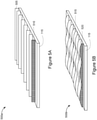
- FIGS 5A and 5B are diagrams of example configurations 500a and 500b of fins suitable for incorporation into an electronic circuit package cooling system 105 shown in Figure 1 .
- the configuration 500a includes a heat transfer plate, such as heat transfer plate 115 shown in Figure 1 .
- the heat transfer plate 115 includes a plurality of fins 505.
- the heat transfer plate 115 also includes one or more coated fins 510.
- the plurality of fins 505 are features of the cooling system 105 that are configured to further enhance the heat transfer performance of the cooling system 105.
- the heat transfer plate 115 is coupled to an ECP such that the heat transfer plate 115 forms the floor or lower portion of the evaporative region of the cooling system chamber.
- the heat transfer plate 115 is configured with a plurality of fins 505 extending away from the heat transfer plate 115 within the sealed enclosure or chamber of the cooling system 105.
- the fins 505 may be configured on the heat transfer plate 115 such that the plurality of fins are uniformly arranged so that each fin 505 has the same height, thickness, gap spacing, and orientation as other fins.
- the heat transfer plate 115 includes a coated fin 510.
- the uniform arrangement of fins 505 may include one or more coated fins 510.
- the coating may include an evaporative surface coating, such as a copper powder that is sintered onto the surface of the fins 510.
- the coating thickness may be a thickness between about .01 and about 1 mm.
- the particle size of the copper powder coating may be a particle size between about .01 and about .2 mm.
- the coated fins 510 may include other surface enhancements to further aid heat transfer performance, such as a metal mesh or surface roughness to increase the surface area of the fin.
- the configuration 500b includes a heat transfer plate, such as the heat transfer plate 115 of Figure 1 .
- the heat transfer plate 115 includes a plurality of fins 515.
- the heat transfer plate also includes one or more coated fins 520.
- the arrangement and function of the plurality of fins that are positioned on the heat transfer plate 115 may enhance the heat transfer performance of the cooling system 105.
- the plurality of fins 515 includes fins that have an irregular shape.
- the configuration 500b includes a plurality of irregularly shaped fins 515, which each have three ridges and a valley between two ridges.
- the fins 515 may be configured on the heat transfer plate 115 such that the plurality of irregularly shaped fins 515 have different heights, thicknesses, gap spaces, and/or orientations.
- the irregular arrangement of the fins 515 may be configured based on the heat map or heat generation profile of the ECP to which the heat transfer plate 115 is attached.
- the heat transfer plate 115 includes a coated fin 520 having an irregular arrangement.
- the irregular arrangement of fins 515 may include one or more coated fins 520.
- the coating may include an evaporative surface coating, such as a copper powder that is sintered onto the surface of the fins 520.
- the coating thickness may be a thickness between about .01 and about 1 mm.
- the particle size of the copper powder coating may be a particle size between about .01 and about .2 mm.
- the irregular arrangement of the coated fins 520 may be configured based on the heat map or heat generation profile of the ECP to which the heat transfer plate 115 is attached so that the heat transfer plate 115 includes a greater density of fins or great fin surface area directly over the regions of the ECP which generate the most heat.
- the heat generation profile of the ECP to which the heat transfer plate 115 is coupled may include three distinct regions which generate high heat and thus require greater heat transfer to maintain proper operating conditions of the ECP components.
- the heat transfer plate 115 may be configured such that the plurality of irregular shaped fins 515 are arranged with greater fin height, thickness and/or density directly over the three highest heat producing regions.
- the three ridges of each irregularly shaped fin 515 may correspond to the three highest heat producing regions of the ECP, while the two valleys of each irregularly shaped fin 515 may correspond to lower heat producing regions of the ECP.
- the coated fins 520 may include other surface enhancements to further aid heat transfer performance, such as a metal mesh or surface roughness to increase the surface area of the fin.
- FIG 6 is a diagram of an example coating configuration 600 within the evaporative region of an electronic circuit package cooling system, such as the cooling system 105 shown in Figure 1 .
- the cooling system 105 includes a coating 605.
- the coating 605 is included on the surfaces of each of the inner walls of the chamber forming evaporative region 120.
- the coating 605 may be an evaporative surface coating, such as a copper powder that is sintered onto the inner wall surface of the chamber forming the evaporative region 120.
- the coating 605 may enhance the heat transfer performance of the cooling system 105 by improving the evaporative efficiency of the heat transfer plate 115 and the inner wall surfaces of the chamber forming the evaporative region 120 to which the coating 605 is applied.
- the coating may include an evaporative surface coating, such as a copper powder that is sintered onto the inner surface of the walls of the chamber forming the evaporative region 120.
- the coating thickness may be a thickness between about .01 and about 1 mm.
- the particle size of the copper powder coating may be a particle size between about .01 and about .2 mm.
- the inner surface of the walls of the chamber forming the evaporative region 120 may include other surface enhancements, such as a metal mesh or surface roughness to increase the surface area of the wall surfaces and further enhance the heat transfer performance of the evaporative region 120.
- FIG 7 is also a diagram of an example coating configuration 700 within the evaporative region of an electronic circuit package cooling system 105 shown in Figure 1 .
- the cooling system 105 includes a coating 705 applied to the surface of the heat transfer plate 115 and also includes a coating 710 applied to the upper portion of the chamber forming the evaporative region 120.
- the coating 705 is included on the surface of the heat transfer plate 115 and covers the heat transfer plate 115 from one side of the evaporative region 120 to the other side of the evaporative region 120.
- the coating 710 is included on the inner surface wall of the upper portion of the chamber forming the evaporative region 120.
- the coating, 705 and/or 710 may be an evaporative surface coating, such as a copper powder that is sintered onto the inner wall surface of the chamber forming the evaporative region 120.
- the coating 705 and/or 710 may enhance the heat transfer performance of the cooling system 105 by improving the absorption of heat from the heat transfer plate 115 and improving the evaporative function of upper portion of the chamber forming the evaporative region 120.
- the coating 705 and/or 710 may include an evaporative surface coating, such as a copper powder that is sintered onto the inner surface of the walls of the chamber forming the evaporative region 120.
- the thickness of coating 705 and/or 710 may be a thickness between about .01 and about 1 mm.
- the coating particle size may be a particle size between about .01 and about .2 mm.
- the inner surface of the walls of the chamber forming the evaporative region 120 may include other surface enhancements, such as a metal mesh or surface roughness to increase the surface area of the wall surfaces and further enhance the heat transfer performance of the evaporative region 120.
- FIG 8 is a diagram of an example coating configuration 800 within the condensing region of an electronic circuit package cooling system, such as the cooling system 105 shown in Figure 1 .
- the cooling system 105 includes a coating 805.
- the coating 805 is included on the inner surfaces of the condensing tubes 130.
- the coating 805 may be a hydrophobic surface coating which functions to reduce the surface friction of the liquid coolant condensed on the inner surface of the walls of the condensing tubes 130. By reducing the surface friction, the coating 805 may facilitate the movement of the condensed liquid coolant back into the evaporative region of the cooling system 105.
- the coating 805 may be a surface coating, such as a sintered copper powder.
- the sintered copper powder may include powder particle sizes between 0.01 mm and 0.5 mm.
- the sintered copper power may be sintered on the inner surface of the condensing tubes 130 to form a surface coating with a thickness between 0.01 mm and 2.0 mm.
- the condensing tubes 130 may include both a coating 805 and a plurality of grooves, such as the grooves 405 as shown in Figure 4 .
- the coating 805 may be applied to the inner surface of the condensing tube walls after a plurality of grooves has been formed on the inner wall surfaces of the condensing tubes 130.
- references to "or” may be construed as inclusive so that any terms described using “or” may indicate any of a single, more than one, and all of the described terms.
- the labels “first,” “second,” “third,” and so forth are not necessarily meant to indicate an ordering and are generally used merely to distinguish between like or similar items or elements.
Landscapes
- Engineering & Computer Science (AREA)
- Physics & Mathematics (AREA)
- Thermal Sciences (AREA)
- Life Sciences & Earth Sciences (AREA)
- Sustainable Development (AREA)
- Mechanical Engineering (AREA)
- General Engineering & Computer Science (AREA)
- Microelectronics & Electronic Packaging (AREA)
- Cooling Or The Like Of Semiconductors Or Solid State Devices (AREA)
- Cooling Or The Like Of Electrical Apparatus (AREA)
- Superconductors And Manufacturing Methods Therefor (AREA)
Abstract
Description
- The present application claims priority to, and the benefit of,
U.S. Patent Application No. 15/797,996, titled "HIGH-PERFORMANCE ELECTRONICS COOLING SYSTEM" and filed on October 30, 2017 - Cooling systems are traditionally used to dissipate heat generated by electronic circuit packages, such as an integrated circuit die package. Heat pipes and vapor chambers are components of such cooling systems. In addition, liquid cooling solutions are also used to transfer heat generated by such electronic circuit packages (ECPs). As ECP manufacturers develop advanced microprocessors for high-performance processing and computing applications, new advances in ECP cooling solutions are needed to adequately manage the increased heat that is generated by these more advanced components.
- According to one aspect, the disclosure relates to a cooling system for an electronic circuit package. The cooling system includes a heat transfer plate positioned in thermal contact with an electronic circuit package surface. The heat transfer plate forms a bottom surface of an evaporative region of the cooling system. The cooling system further includes a plurality of condensing tubes in fluid communication with, and extending away from, the evaporative region. The evaporative region and condensing tubes together form a single, uninterrupted, sealed enclosure. The cooling system further includes a fluid disposed within the sealed disclosure. The cooling system further includes a plurality of spacers substantially filling gaps between the heat transfer plate and respective condensing tubes. Each of the spacers is configured as an independent component to allow the passage of fluid through an interior space of each spacer. The cooling system further includes a plurality of wicks. Each wick is positioned partially within a corresponding spacer to which the spacer is fluidically coupled.
- In some implementations, at a least a portion of each wick contacts the heat transfer plate. In some implementations, the portion of each wick in contact with the heat transfer plate is oriented substantially parallel to the heat transfer plate. In some implementations, the portion of each wick in contact with the heat transfer plate covers less than three-quarters of a cross sectional area of an end of a corresponding spacer. In some implementations, the portion of each wick in contact with the heat transfer plate substantially covers an end of its corresponding spacer and extends in a direction parallel to the heat transfer plate beyond an edge of the corresponding spacer. In some implementations, each wick comprises a metal mesh. In some implementations, each spacer extends at least partially into a corresponding condensing tube. In some implementations, an inner surface of each condensing tube defines a plurality of grooves. In some implementations, the heat transfer plate comprises a plurality of fins extending away from the heat transfer plate within the sealed enclosure. In some implementations, the plurality of fins are arranged in an irregular fashion. In some implementations, the plurality of fins are arranged based on a variation in heat generation across the electronic circuit package surface in thermal contact with the heat transfer plate. In some implementations, at least a portion of the sealed enclosure is coated with a copper powder. In some implementations, the copper powder coating the sealed enclosure has a particle size of about 0.1 mm. In some implementations, the copper powder coating the sealed enclosure forms a coating having a thickness of about 0.3 mm. In some implementations, the copper powder coating coats a plurality of fins extending away from the heat transfer plate within the sealed enclosure. In some implementations, the copper powder coating coats at least one of the heat transfer plate and a surface of the evaporative region opposite the heat transfer plate within the sealed enclosure. In some implementations, the interiors of the condensing tubes are free from the copper powder coating. In some implementations, a diameter of each spacer flares outward proximate to the heat transfer plate. In some implementations, a portion of each spacer extends closer to the cooling plate than a remainder of the spacer. In some implementations, the condensing tubes are positioned about a perimeter of the sealed enclosure.
- According to another aspect, the disclosure relates to a cooling system for an electronic circuit package. The cooling system includes a heat transfer plate positioned in thermal contact with an electronic circuit package surface. The heat transfer plate forms a bottom surface of an evaporative region of the cooling system. The cooling system further includes a plurality of condensing tubes in fluid communication with, and extending away from, the evaporative region. The evaporative region and condensing tubes together form a single, uninterrupted, sealed enclosure. Each of the plurality of condensing tubes includes a plurality of grooves. The cooling system further includes a fluid disposed within the sealed disclosure. The cooling system includes a plurality of wicks. Each wick is positioned such that one end is in contact with the heat transfer plate and an opposite end extends into a proximal end of a corresponding condensing tube for a distance that is less than 5% of the length of the corresponding condensing tube. In some implementations, each wick comprises a multi-layer copper mesh.
- The above and related objects, features, and advantages of the present disclosure will be more fully understood by reference to the following detailed description, when taken in conjunction with the following figures, wherein:
-
Figure 1 is a diagram of an example electronic circuit package cooling system. -
Figures 2A-2G describe multiple example configurations of spacers and wicks suitable for use in an electronic circuit package cooling system according to some implementations. -
Figure 3 is a top view of the example electronic circuit package cooling system illustrating an example arrangement of condensing tubes in an electronic circuit package cooling system according to some implementations. -
Figure 4 is a diagram of the electronic circuit package cooling system illustrating an example arrangement of grooved condensing tubes in an electronic circuit package cooling system according to some implementations. -
Figures 5A and 5B are diagrams of example configurations of fins suitable for incorporation into an electronic circuit package cooling system according to some implementations. -
Figures 6 and7 are diagrams of example coating configurations within the evaporative region of an electronic circuit package cooling system according to some implementations. -
Figure 8 is a diagram of an example coating configuration within the condensing region of an electronic circuit package cooling system according to some implementations. - Heat dissipation is a major concern for manufacturers of electronic circuit packages, such as an integrated circuit die package. As manufacturers create electronic circuit packages (ECPs) with greater computing and processing capabilities, the need for improved cooling solutions also increases in order for users to gain the full benefit of these high-performance electronic circuit designs without being hindered by performance degradations due to sub-optimal management of heat that is generated by the more powerful ECP. Heat pipes and vapor chambers have often been used in this domain to cool ECPs. Typically, in legacy solutions, as ECP power increases, the cooling performance declines because the solutions are unable to dissipate enough heat at a fast enough rate to ensure optimal performance of the ECP. Often the cooling capacity of a particular heat pipe or vapor chamber design does not match the heat generation profile of a given ECP for which the cooling solution has been applied. As a result, temperatures in the ECP rise which can degrade ECP performance and/or negatively impact the life-span and reliability of the ECP. Cooling solutions that include liquid cooling methods are available but often involve increased cost and design complexity. The cooling systems disclosed herein can avoid the expensive design, manufacturing, and maintenance requirements that are typically associated with liquid cooling solutions. The disclosed cooling systems are also well-suited for deployment with high-power components (e.g., processors performing computationally intensive operations, such as machine learning applications) and may enable use of higher processor speeds to increase chip performance.
- The disclosed cooling systems include a number of features to improve heat transfer away from an ECP to which the cooling system is attached. These features, alone and/or in combination, can help enable the evaporation process to be improved, and in some cases optimized, for a particular heat source, resulting in more efficient and consistent heat transfer away from high power density ECPs. The disclosed cooling systems may include a single continuous liquid-vapor chamber. The chamber may include an evaporator plate, which is in contact with the ECP and transfers heat into a liquid coolant that is included in the chamber. The liquid coolant may then evaporate as heat is absorbed from the ECP and the moisture vapor generated from the evaporating liquid may accumulate in the condensing tubes. In the condensing tubes, the heat contained in the moisture vapor may be transferred to the condensing tube walls and consequently to an external cooling medium (which may include water or air, or other fluids). The liquid condensate that accumulates on the inner surface of the condensing tube walls may then flow back to the evaporative region from the condensing tubes. The cooling system can include independent structures, referred to herein as spacers that fluidically couple the condensing tubes to the evaporative region. Such spacers may include a rigid component and/or a wick, to provide a continuous flow of liquid coolant for more efficient heat transfer. The spacer may act as a "bridge" between the end of the condensing tubes closest to the evaporator plate (referred to as the "proximal end") and the heat transfer plate of the evaporative portion of the chamber. The wicks may provide a wicking effect, drawing the condensate liquid from the condensing tubes back down into the evaporative portion of the chamber, rather than allowing the liquid to accumulate in the proximal end of the condensing tubes and drip down into the evaporator plate.
- As an additional feature, the inner walls of the evaporative portion of the chamber may include surface coatings to improve evaporation efficiency. For example, a copper powder may coat the heat transfer plate and the surfaces of the chamber that are opposite the heat transfer plate. In some implementations, the surface coating may also coat the walls of the chamber and/or the inner walls of the condensing tubes. In some implementations, the inner walls of the condensing tubes lack a surface coating, and instead include a series of longitudinal grooves that extend the length of the condensing tubes.
- In some implementations, the wick may include a multi-layer copper mesh extending between the condensing tubes and the heat transfer plate. In addition, fins may also be added to the internal surface of the heat transfer plate to increase the surface area of the heat transfer plate. The fins may also be coated with a copper coating to boost the evaporative efficiency of the cooling system.
- The heat transfer plate may be attached to an upper portion of the chamber to form an enclosed, single-volume, continuous liquid-vapor cooling system. The condensing tubes may be connected to the sides of this enclosed chamber or to the top (or a combination of both connection configurations). As described above, the condensing tubes may include a wick to provide a capillary effect and improve fluid circulation between the evaporative and condensing regions of the chamber. Alternatively or in addition, the condensing tubes may include grooves to reduce the friction of the condensate on the condensing tube inner walls and may facilitate movement of the condensate back to the evaporative region.
- The disclosed cooling system architecture enhances the air cooling capacity of the condensing tubes and addresses the problem of managing high heat flux that is typically generated by high power ASICs or microprocessors. Often, the configuration of high power processors included in an ECP can greatly affect the heat transfer performance of the cooling system used to cool the ECP. A solution to this problem may include a cooling system that is optimized for the configuration or layout of the high-performance components that are included in a particular ECP configuration. For example, an ECP configuration may be arranged such that numerous microprocessors are positioned around the perimeter of the ECP. A cooling system that includes design elements in the center of the ECP may not demonstrate the same heat transfer capabilities as a cooling system configured with heat transfer features that are similarly mapped or positioned in relation to the heat generating components of the ECP, such as cooling system features that are configured around the perimeter of the cooling system in positions corresponding to the heat generating processors of the ECP. One way the disclosed cooling systems disclosed herein address this problem is by enabling an ECP manufacturer to customize the shape, elevation and density of a plurality of fins that may be arranged on the heat transfer plate that is coupled to the ECP. The fins may be arranged in a uniform pattern or an irregular pattern that is designed to optimize the heat transfer away from the heat generating portions of the ECP over which the fins are located. In the disclosed cooling system, regions of the ECP with a greater density of heat-generating ASICs or microprocessors may be mapped and a heat transfer plate may be manufactured with a plurality of fins whose location, density and coating properties may be optimized to efficiently manage the heat generated by the microprocessors. For example, regions of the heat transfer plate located above components of an ECP that generate greater amounts of heat may be include a greater number of fins, a greater fin surface area, or a greater fin density (and thus greater heat transfer capacity) than regions of the heat transfer plate located above lower-powered integrated circuits in the ECP over which the heat transfer plate is located.
- Additional details of the various design elements included in the disclosed cooling system will now be described in more detail.
-
Figure 1 is a diagram of an example electronic circuitpackage cooling system 105. In broad overview, thecooling system 105 is coupled to an electronic circuit package (ECP) 110, such as an integrated circuit die package. TheECP 110 may further include one or more microprocessors, such as ASICs, field programmable gate arrays (FPGAs), or microprocessors. Thecooling system 105 also includes aheat transfer plate 115. The cooling system includes anevaporative region 120 and a plurality of condensingregions 125. Thecooling system 105 includes a plurality of condensingtubes 130 and a plurality ofspacers 135. Thecooling system 105 also includes a plurality ofwicks 140. - As shown in
Figure 1 , thecooling system 105 is formed as a single, uninterrupted, sealed enclosure or chamber. Thecooling system 105 includes aheat transfer plate 105 forming the bottom or lower portion of the chamber and a plurality of condensingtubes 130 forming an upper portion of the chamber. Thecooling system 105 includes anevaporative region 120 and a plurality of condensingregions 125, located within the condensingtubes 130. The upper portion of the chamber may be fitted as a lid to the lower portion of the chamber to create the single, continuous volume chamber. In some implementations, the chamber may include a liquid (e.g., water or a coolant fluid) to absorb the heat that is generated by theECP 110. The generated heat is absorbed by the liquid within theevaporative region 120 and transferred to the condensingregion 125 as the liquid evaporates. The evaporated liquid is transferred to the condensingtubes 130 as vapor where, as the vapor condenses on the walls of the condensingtubes 130, the heat is dissipated through the walls of the condensingtubes 130 into an external cooling medium surrounding the condensingtubes 130, such as air or water or another fluid. The condensate may then flow from the walls of the condensingtubes 130 back to theevaporative region 120. - The design of the single, continuous volume liquid-vapor chamber of the
cooling system 105 may provide the benefit of allowing all the condensingtubes 130 to operate at the same temperature (assuming equal vapor pressure inside). In this way, the condensingtubes 130, when connected to the same chamber or volume of space (e.g., the evaporative region 120) and exposed to the lower temperature liquid present in theevaporative region 120, may transfer a higher heat load than if the condensingtubes 130 were not connected to the same chamber or volume of space or were otherwise located downstream of the liquid coolant. Thus, a single, continuous volume liquid-vapor chamber avoids uneven heat balancing among the condensingtubes 130 and further avoids intermediate thermal resistances, such as solder thermal resistance and/or copper heat spreader resistance that may form between theheat transfer plate 115 and the external cooling medium, e.g., air or water, in cooling system designs which include multiple internal chambers or heat dissipation structures. - As shown in
Figure 1 , aheat transfer plate 110 is coupled to theECP 105. Theheat transfer plate 105 is positioned directly atop and mated to anECP 105 so that heat generated byECP 105 may be transmitted to theheat transfer plate 110 for further dissipation. Theheat transfer plate 110 may be constructed of a metal or metal alloy possessing superior heat transfer qualities, such as copper or aluminum, so that the heat that is generated by theECP 105 is efficiently transferred to theheat transfer plate 110 and into thecooling system 105 for further dissipation. Theheat transfer plate 115 forms the lower portion or floor of the chamber formed by thecooling system 105. In some implementations, theheat transfer plate 115 may be coupled to theECP 110 using a thermal transfer material. - As shown in
Figure 1 , thecooling system 105 includes anevaporative region 120. Theevaporative region 120 receives the heat generated by theECP 110 and transferred to theheat transfer plate 115 to which it is coupled. Theevaporative region 120 is the volume of space formed byheat transfer plate 115, the walls, and upper portion of the chamber of thecooling system 105. Theevaporative region 120 may include a liquid, such as water or a coolant fluid (not shown), such as a dielectric refrigerant. The heat transferred from theheat plate 115 is absorbed by the liquid in theevaporative region 120 causing the liquid to evaporate into a vapor phase. The vapor carrying the transferred heat accumulates and condenses in the condensingregions 125. In some implementations, thecooling system 105 may include a fill tube (not shown) which is used in the manufacturing process to charge thecooling system 105 with a certain amount of liquid coolant or water. In some implementations, the volume of coolant to be used may be a volume which occupies between 10% and 50% of the internal volume of the cooling system chamber. The weight or amount of liquid that may be used to charge thecooling system 105 may be optimized or configured based on the power (and heat) map that is associated with the ECP to which thecooling system 105 is coupled. - As shown in
Figure 1 , thecooling system 105 also includes a plurality of condensingregions 125. The condensingregions 125 are the volumes of space formed by the walls of the condensingtubes 130. The condensingregions 125 accumulate the evaporated liquid which was transformed into vapor and carries the heat transferred from theheat transfer plate 115 into theevaporative region 120. The vapor collects in the condensingregions 125 and condenses on the walls of the condensingtubes 130. The dimensions of the condensingregions 125 and the condensingtubes 130 from which they are formed may vary based on the heat transfer performance desired for aparticular cooling system 105 and/orparticular ECP 110. In some implementations, the condensingtubes 130 have a hydraulic diameter of approximately 2-15 mm and are approximately 20-500 mm tall. The condensingtubes 130 may be circular, rectangular, triangular, octagonal or have any other cross sectional shape. In some implementations, the condensingtubes 130 may be straight. In some implementations, the condensingtubes 130 may be bent at an angle. In some implementations, the condensingtubes 130 may be arranged vertically in relation to theheat transfer plate 115. In some implementations, the condensingtubes 130 may be arranged horizontally in relation to theheat transfer plate 115. - The condensing
tubes 130 may be constructed of a metal or metal alloy with desirable heat transfer qualities, such as copper or aluminum, so that the heat that is present in the vapor which accumulates on the walls of the condensingtubes 130 may be efficiently transferred to an external medium surrounding the condensingtubes 130 such as air or water, allowing the vapor to condense back into a liquid phase. In some implementations, the inner surface of the condensingtubes 130 may include a coating, such as a copper powder coating. In other implementations, the inner surface of the condensingtubes 130 may be free of the copper powder coating, and may instead include a series of longitudinal grooves that extend the length or substantially the entire length of the condensingtubes 130. - As shown in
Figure 1 , thecooling system 105 may include a plurality ofspacers 135. Thespacers 135 are independent components spanning the space within theevaporative region 120. Thespacers 135 fill gaps between the between theheat transfer plate 115 and therespective condensing tubes 125. Thespacers 135 are generally tubular and are configured to allow passage of fluid through the interior space of each spacer. Thespacers 135 may improve the overall dry-out power of the condensingtube 130 to which it is attached by facilitating the flow of condensed evaporative liquid back toward theevaporative region 120. In some implementations, thespacers 135 may include a rigid outer structure such as a copper tube. In some implementations, the inner surface of thespacers 135 may include a coating to assist movement of the evaporative liquid back to theevaporative region 120. In some implementations, thespacers 135 may include a mesh wick in addition to the rigid outer structure. In some implementations, thespacers 135 may include only a metal mesh spacer and do not include a rigid outer structure. - As further shown in
Figure, 1 thecooling system 105 includes a plurality ofwicks 140. Thewicks 140 provide a wicking (or capillary) effect to draw the condensed vapor that has accumulated at the lower portion of the condensingtubes 130 back to theevaporative region 120. For example, as heat is transferred through the walls of the condensingtubes 130, the vapor that carried the heat condenses on the walls of the condensingtubes 130 and migrates down the inner surface of the condensing tubes. The condensed liquid may accumulate at the lower portion of the condensingtubes 130. Thewicks 140 may draw or wick the accumulated liquid from the lower portion of the condensingtubes 130 further down into the evaporative region near theheat transfer plate 115. Thewicks 140 may enable a steady, continuous flow of liquid coolant through thecooling system 105 resulting in more uniform temperatures and greater heat transfer performance in all condensingtubes 130 compared to cooling system designs that utilize condensing tubes without a wick. In some implementations, thewick 140 may be included as a component of thespacer 135. In other implementations, thewick 140 may not be included as a component of thespacer 135. -
Figures 2A-2G describe multiple example configurations of spacers and wicks suitable for use in the cooling system shown 105 shown inFigure 1 .Figures 2A-2F show aspects of various implementations of thecooling system 105, includingheat transfer plates 215a-215f, condensing tubes 230a-230f, spacers 235a-235f, andwicks 240a-240f.Figure 2G shows an implementation of a cooling system that includes all the elements ofFigures 2A-2F , but excludes a spacer. - As shown in
Figure 2A , thecooling system 105 includes a spacer 235a that is positioned at the lower portion of the condensing tube 230a and extends at least partially into the corresponding condensing tube 230a. The spacer 235a spans substantially the entire evaporative region (e.g. between about 80%-100% of the gap between the end of the condensing tubes closest to the evaporator plate (referred to as the "proximal end") and the heat transfer plate of the evaporative portion of the chamber) such that one end of the spacer 235a is inserted into the condensing tube 230a, and the other end of the spacer 235a is in close proximity to or in contact with theheat transfer plate 215a. In some implementations, the inner surface of the spacer 235a may include a coating to facilitate the return of the condensed liquid coolant back to the evaporative region via the inner surfaces of the spacer 235a. For example, the inner surface of the spacer 235a may include a hydrophobic surface coating to reduce the surface friction of the liquid coolant and may facilitate movement of the liquid coolant from the condensing tube 230a back into the evaporative region of thecooling system 105. - As further shown in
Figure 2A , the spacer 235a includes awick 240a. Thewick 240a is positioned partially within the condensing tube 230a to which it is fluidically coupled. Thewick 240a is positioned within the inner volume of the spacer 235a and extends upward to the lower portion of the condensing tube 230a. The spacer 235a extends downward toward theheat transfer plate 215a. Thewick 240a is in contact with theheat transfer plate 215a. The portion of thewick 240a in contact with theheat transfer plate 215a is oriented substantially parallel to theheat transfer plate 215a for which it is in contact. In some implementations, the portion of thewick 240a in contact with theheat transfer plate 215a may be configured to cover different cross sectional dimensions of the spacer 235a to which it corresponds. In some implementations, the portion of thewick 240a that is oriented substantially parallel to theheat transfer plate 215a, may cover between 15-30% of the cross sectional area of an end of the corresponding spacer 235a, for example 25% of the cross sectional area of an end of the corresponding spacer 235a. In some implementations, the portion of thewick 240a that is oriented substantially parallel to theheat transfer plate 215a, may cover between 40-60% of the cross sectional area of an end of the corresponding spacer 235a, for example 50% of the cross sectional area of an end of the corresponding spacer 235a. In some implementations, the portion of thewick 240a that is oriented substantially parallel to theheat transfer plate 215a, may cover between 70-90% of the cross sectional area of an end of the corresponding spacer 235a, for example 75% of the cross sectional area of an end of the corresponding spacer 235a. - As shown in
Figure 2B , all of the elements described in relation toFigure 2A remain the same, except that thewick 240b shown inFigure 2B extends beyond thespacer 235b and further into the proximal end of the condensingtube 230b. Extending thewick 240b further into the condensing region created by the condensingtube 230b may provide a greater wicking effect and draw a greater amount of liquid coolant that has condensed on the inner surfaces of the condensingtube 230b back toward theheat transfer plate 215b. In some implementations, thewick 240b may extend into the proximal end of condensingtube 230b for a distance that is between 0-10% of the length of the corresponding condensing tube, for example less than 5% of the length of the corresponding condensing tube. In some implementations, thewick 240b may extend into the proximal end of condensingtube 230b for a distance that is between 10-50% of the length of the corresponding condensing tube, for example 35% of the length of the corresponding condensing tube. In some implementations, thewick 240b may extend into the proximal end of condensingtube 230b for a distance that is between 50-100% of the length of the corresponding condensing tube, for example 75% of the length of the corresponding condensing tube. - As shown in
Figure 2C , all of the elements described in relation toFigure 2A remain the same, except that thespacer 235c shown inFigure 2C is configured to flare outward proximate to the heat transfer plate 215c. For example, the diameter of the spacer proximate to the heat transfer plate 215c can be between 1.25-2.0 times the diameter of the spacer where it enters the condensingtube 230c. - As shown in
Figure 2D , all of the elements described in relation toFigure 2C remain the same, except that the wick 240d shown inFigure 2D is configured to extend beyond thespacer 235d and further into the proximal end of the condensingtube 230d, similar to thewick 240b as shown inFigure 2B . In some implementations, the wick 240d may extend into the proximal end of condensingtube 230d for a distance that is between 0-10% of the length or height of the corresponding condensing tube, for example less than 5% of the length of the corresponding condensing tube. In some implementations, the wick 240d may extend into the proximal end of condensingtube 230d for a distance that is between 10-50% of the length or height of the corresponding condensing tube, for example 35% of the length of the corresponding condensing tube. In some implementations, the wick 240d may extend into the proximal end of condensingtube 230d for a distance that is between 50-95% of the length or height of the corresponding condensing tube, for example 75% of the length of the corresponding condensing tube. - As shown in
Figure 2E , all of the elements described in relation toFigure 2A remain the same, except that as shown inFigure 2E , the portion of thewick 240e that is oriented substantially parallel to theheat transfer plate 215e extends to cover a smaller portion of the cross sectional area of an end of the corresponding spacer 235e than thewick 240a shown inFigure 2A . For example, the portion of thewick 240e that is oriented substantially parallel to theheat transfer plate 215e may extend to cover 5% of the cross sectional area of an end of the spacer 235e. In some implementations, the portion of the wick that is oriented substantially parallel to theheat transfer plate 215e may extend to cover less, than 5%, less than 10%, or less than 20% of the cross sectional area of an end of the spacer 235e. In some implementations, the wick shown inFigure 2E may be configured within a flared spacer, such asspacer 235c ofFigure 2C . In some implementations, thewick 240e shown inFigure 2E may be configured to extend substantially into the condensing tube 230e as shown by thewick 240b inFigure 2B . In some implementations, thewick 240e ofFigure 2E may be configured in a flared spacer, such asspacer 235d inFigure 2D and may be further configured to extend through the flared spacer substantially into the corresponding condensing tube 230e, such as the wick 240d shown inFigure 2D . - As shown in
Figure 2F , all of the elements described in relation toFigure 2A remain the same, except that as shown inFigure 2F , a portion of thewick 240f extends to cover an end of itscorresponding spacer 235f and further extends in a direction beyond an edge of thecorresponding spacer 235f. In some implementations, the portion of thewick 240f that is oriented substantially parallel to theheat transfer plate 215f may extend beyond an edge of thecorresponding spacer 235f by approximately 0-10% of the width or diameter of the corresponding spacer. For example the portion of thewick 240f that is oriented substantially parallel to theheat transfer plate 215f may extend beyond an edge of thecorresponding spacer 235f by approximately less than 5% of the width or diameter of thecorresponding spacer 235f. In some implementations, the portion of thewick 240f that is oriented substantially parallel to theheat transfer plate 215f may extend beyond an edge of thecorresponding spacer 235f by approximately 15-50% of the width or diameter of the corresponding spacer. For example the portion of thewick 240f that is oriented substantially parallel to theheat transfer plate 215f may extend beyond an edge of thecorresponding spacer 235f by approximately 45% of the width or diameter of thecorresponding spacer 235f. In some implementations, the portion of thewick 240f that is oriented substantially parallel to theheat transfer plate 215f may extend beyond an edge of thecorresponding spacer 235f by approximately 60-90% of the width or diameter of the corresponding spacer. For example the portion of thewick 240f that is oriented substantially parallel to theheat transfer plate 215f may extend beyond an edge of thecorresponding spacer 235f by approximately 85% of the width or diameter of thecorresponding spacer 235f. In some implementations, the wick shown inFigure 2F may be configured within a flared spacer, such asspacer 235c ofFigure 2C . In some implementations, thewick 240f shown inFigure 2F may be configured to extend substantially into the condensingtube 230f as shown by thewick 240b inFigure 2B . In some implementations, thewick 240f ofFigure 2F may be configured in a flared spacer, such asspacer 235d inFigure 2D , and may be further configured to extend through the flared spacer substantially into thecorresponding condensing tube 230f, such as the wick 240d shown inFigure 2D . - As shown in
Figure 2G , thewick 240g is positioned similarly to thewick 240a described inFigure 2A , however thecooling system 105 shown inFigure 2G excludes a spacer, such as the spacer 235a shown inFigure 2A . Thewick 240g shown inFigure 2G is configured positioned such that one end is in contact with theheat transfer plate 215g and the opposite end extends into a proximal end of acorresponding condensing tube 230g for a distance that is between 0-10% of the length or height of the corresponding condensing tube, for example less than 5% of the length or height of thecorresponding condensing tube 230g. In some implementations, thewick 240g may extend into the proximal end of condensingtube 230g for a distance that is between 10-50% of the length or height of the corresponding condensing tube, for example 40% of the length of the corresponding condensing tube. In some implementations, thewick 240g may extend into the proximal end of condensingtube 230g for a distance that is between 50-100% of the length or height of the corresponding condensing tube, for example 80% of the length of the corresponding condensing tube. In some implementations, thewick 240g includes a metal mesh wick. For example, thewick 140 may include a copper mesh wick. In some implementations, thewick 240g includes a multi-layer metal mesh, such as a multi-layer copper mesh wick. - In some implementations, the portion of the
mesh wick 240g in contact with theheat transfer plate 215g may extend to cover a small portion of the cross sectional area of the condensingtube 230g. For example, the portion of thewick 240g that is oriented substantially parallel to theheat transfer plate 215g may extend to cover less than 5% of the cross sectional area of the condensingtube 230g. In some implementations, the portion of the wick that is oriented substantially parallel to theheat transfer plate 215g may extend to cover 10-40% of the cross sectional area of the condensingtube 230g, for example 25% of the cross sectional area of the condensingtube 230g. In some implementations, the portion of the wick that is oriented substantially parallel to theheat transfer plate 215g may extend to cover 40-90% of the cross sectional area of the condensingtube 230g, for example 75% of the cross sectional area of the condensingtube 230g. - In some implementations, the portion of the
wick 240g that is oriented substantially parallel to theheat transfer plate 215g extends to cover an end of itscorresponding condensing tube 230g and further extends in a direction beyond an edge of thecorresponding condensing tube 230g. In some implementations, the portion of thewick 240g that is oriented substantially parallel to theheat transfer plate 215g may extend beyond an edge of thecorresponding condensing tube 230g by approximately 0-10% of the width or diameter of the corresponding condenser tube. For example the portion of thewick 240g that is oriented substantially parallel to theheat transfer plate 215g may extend beyond an edge of thecorresponding condensing tube 230g by approximately less than 5% of the width or diameter of thecorresponding condenser tube 230g. In some implementations, the portion of thewick 240g that is oriented substantially parallel to theheat transfer plate 215g may extend beyond an edge of thecorresponding condensing tube 230g by approximately 15-50% of the width or diameter of the corresponding condenser tube. For example the portion of thewick 240g that is oriented substantially parallel to theheat transfer plate 215g may extend beyond an edge of thecorresponding condensing tube 230g by approximately 45% of the width or diameter of thecorresponding condenser tube 230g. In some implementations, the portion of thewick 240g that is oriented substantially parallel to theheat transfer plate 215g may extend beyond an edge of thecorresponding condensing tube 230g by approximately 60-90% of the width or diameter of the corresponding condenser tube. For example the portion of thewick 240g that is oriented substantially parallel to theheat transfer plate 215g may extend beyond an edge of thecorresponding condensing tube 230g by approximately 85% of the width or diameter of thecorresponding condenser tube 230g. -
Figure 3 is a top view of theexample cooling system 105 shown inFigure 1 , illustrating anexample arrangement 300 of condensingtubes 130 in an electronic circuitpackage cooling system 105. Thearrangement 300 includes a plurality of condensingtubes 130 positioned about the perimeter of theupper surface 305 of the chamber or sealed enclosure of thecooling system 105. In some implementations, the positioning of the coolingtubes 130 may be determined in relation to a heat map or heat generation profile of the ECP to which thecooling system 105 is attached. For example, in some implementations, if the ECP generates more heat towards the center of the ECP, the plurality of condensingtubes 105 may be positioned towards the center of the chamber of thecooling system 105. In other implementations, the condensingtubes 130 may be positioned in the corners or on opposite sides of the chamber of thecooling system 105. -
Figure 4 is a diagram of the electronic circuit package cooling system illustrating anexample arrangement 400 of grooved condensing tubes in an electronic circuitpackage cooling system 105 shown inFigure 1 . As shown inFigure 4 , thecooling system 105 includes the same elements as thecooling system 105 shown inFigure 1 , except that the inner surface of each condensingtube 130 includes a plurality ofgrooves 405. The plurality ofgrooves 405 are oriented vertically within the condensingtubes 130 when the condensingtubes 130 are positioned atop the chamber of thecooling system 105 as shown inFigure 4 . In configurations where the condensing tubes are located on the sides of the chamber of the cooling system 105 (not shown), the plurality ofgrooves 405 may be oriented in a manner such that the grooves are parallel to the length of the condensingtubes 130. Thegrooves 405 that are in the inner walls of the condensingtubes 130 may provide a capillary effect for condensed liquid coolant and may act as channels for the flow of condensed liquid coolant to return to theevaporative region 120, thereby reducing the condensation fluid resistance on the inner surface of the condensing tube walls. By aiding the return of the liquid coolant to theevaporative region 120, the heat transfer performance of thecooling system 105 may be enhanced as the system is able to cycle the liquid coolant more quickly from the evaporative region to the condensing region and back again to the evaporative region. - A variety of groove configurations may be applied to the inner surface of the condensing
tubes 130. In some implementations, the groove shape or cross sectional profile of the grooves may be a rectangular shape, a square shape, a rounded shape, and/or "v"-shape. In some implementations, a mixture of groove shapes, depths and/or spacing configurations may be used within one ormore condensing tubes 130 ofcooling system 105. In some implementations, the depth of each groove may be between 0.05 mm to 1 mm. In some implementations, the spacing between each groove may be between 0.05 mm to 1 mm. -
Figures 5A and 5B are diagrams ofexample configurations package cooling system 105 shown inFigure 1 . As shown inFigure 5A , theconfiguration 500a includes a heat transfer plate, such asheat transfer plate 115 shown inFigure 1 . Theheat transfer plate 115 includes a plurality offins 505. Theheat transfer plate 115 also includes one or morecoated fins 510. In broad terms, the plurality offins 505 are features of thecooling system 105 that are configured to further enhance the heat transfer performance of thecooling system 105. As described in relation toFigure 1 , theheat transfer plate 115 is coupled to an ECP such that theheat transfer plate 115 forms the floor or lower portion of the evaporative region of the cooling system chamber. As shown inFigure 5A , theheat transfer plate 115 is configured with a plurality offins 505 extending away from theheat transfer plate 115 within the sealed enclosure or chamber of thecooling system 105. Thefins 505 may be configured on theheat transfer plate 115 such that the plurality of fins are uniformly arranged so that eachfin 505 has the same height, thickness, gap spacing, and orientation as other fins. - As further shown in
Figure 5A , theheat transfer plate 115 includes acoated fin 510. The uniform arrangement offins 505 may include one or morecoated fins 510. The coating may include an evaporative surface coating, such as a copper powder that is sintered onto the surface of thefins 510. In some implementations, the coating thickness may be a thickness between about .01 and about 1 mm. In some implementations, the particle size of the copper powder coating may be a particle size between about .01 and about .2 mm. In some implementations, thecoated fins 510 may include other surface enhancements to further aid heat transfer performance, such as a metal mesh or surface roughness to increase the surface area of the fin. - As shown in
Figure 5B , theconfiguration 500b includes a heat transfer plate, such as theheat transfer plate 115 ofFigure 1 . Theheat transfer plate 115 includes a plurality offins 515. The heat transfer plate also includes one or morecoated fins 520. As described in relation toFigure 5A , the arrangement and function of the plurality of fins that are positioned on theheat transfer plate 115 may enhance the heat transfer performance of thecooling system 105. The plurality offins 515 includes fins that have an irregular shape. For example, as shown inFigure 5B , theconfiguration 500b includes a plurality of irregularly shapedfins 515, which each have three ridges and a valley between two ridges. Thefins 515 may be configured on theheat transfer plate 115 such that the plurality of irregularly shapedfins 515 have different heights, thicknesses, gap spaces, and/or orientations. In some implementations, the irregular arrangement of thefins 515 may be configured based on the heat map or heat generation profile of the ECP to which theheat transfer plate 115 is attached. - As further shown in
Figure 5B , theheat transfer plate 115 includes acoated fin 520 having an irregular arrangement. For example, the irregular arrangement offins 515 may include one or morecoated fins 520. The coating may include an evaporative surface coating, such as a copper powder that is sintered onto the surface of thefins 520. In some implementations, the coating thickness may be a thickness between about .01 and about 1 mm. In some implementations, the particle size of the copper powder coating may be a particle size between about .01 and about .2 mm. The irregular arrangement of thecoated fins 520 may be configured based on the heat map or heat generation profile of the ECP to which theheat transfer plate 115 is attached so that theheat transfer plate 115 includes a greater density of fins or great fin surface area directly over the regions of the ECP which generate the most heat. For example, the heat generation profile of the ECP to which theheat transfer plate 115 is coupled may include three distinct regions which generate high heat and thus require greater heat transfer to maintain proper operating conditions of the ECP components. Accordingly, theheat transfer plate 115 may be configured such that the plurality of irregular shapedfins 515 are arranged with greater fin height, thickness and/or density directly over the three highest heat producing regions. As shown inFigure 5B , the three ridges of each irregularly shapedfin 515 may correspond to the three highest heat producing regions of the ECP, while the two valleys of each irregularly shapedfin 515 may correspond to lower heat producing regions of the ECP. In some implementations, thecoated fins 520 may include other surface enhancements to further aid heat transfer performance, such as a metal mesh or surface roughness to increase the surface area of the fin. -
Figure 6 is a diagram of anexample coating configuration 600 within the evaporative region of an electronic circuit package cooling system, such as thecooling system 105 shown inFigure 1 . As shown inFigure 6 , thecooling system 105 includes acoating 605. Thecoating 605 is included on the surfaces of each of the inner walls of the chamber formingevaporative region 120. Thecoating 605 may be an evaporative surface coating, such as a copper powder that is sintered onto the inner wall surface of the chamber forming theevaporative region 120. Thecoating 605 may enhance the heat transfer performance of thecooling system 105 by improving the evaporative efficiency of theheat transfer plate 115 and the inner wall surfaces of the chamber forming theevaporative region 120 to which thecoating 605 is applied. The coating may include an evaporative surface coating, such as a copper powder that is sintered onto the inner surface of the walls of the chamber forming theevaporative region 120. In some implementations, the coating thickness may be a thickness between about .01 and about 1 mm. In some implementations, the particle size of the copper powder coating may be a particle size between about .01 and about .2 mm. In some implementations, the inner surface of the walls of the chamber forming theevaporative region 120 may include other surface enhancements, such as a metal mesh or surface roughness to increase the surface area of the wall surfaces and further enhance the heat transfer performance of theevaporative region 120. -
Figure 7 is also a diagram of anexample coating configuration 700 within the evaporative region of an electronic circuitpackage cooling system 105 shown inFigure 1 . As shown inFigure 7 , thecooling system 105 includes acoating 705 applied to the surface of theheat transfer plate 115 and also includes acoating 710 applied to the upper portion of the chamber forming theevaporative region 120. Thecoating 705 is included on the surface of theheat transfer plate 115 and covers theheat transfer plate 115 from one side of theevaporative region 120 to the other side of theevaporative region 120. Thecoating 710 is included on the inner surface wall of the upper portion of the chamber forming theevaporative region 120. The coating, 705 and/or 710, may be an evaporative surface coating, such as a copper powder that is sintered onto the inner wall surface of the chamber forming theevaporative region 120. Thecoating 705 and/or 710 may enhance the heat transfer performance of thecooling system 105 by improving the absorption of heat from theheat transfer plate 115 and improving the evaporative function of upper portion of the chamber forming theevaporative region 120. Thecoating 705 and/or 710 may include an evaporative surface coating, such as a copper powder that is sintered onto the inner surface of the walls of the chamber forming theevaporative region 120. In some implementations, the thickness ofcoating 705 and/or 710 may be a thickness between about .01 and about 1 mm. In some implementations, the coating particle size may be a particle size between about .01 and about .2 mm. In some implementations, the inner surface of the walls of the chamber forming theevaporative region 120 may include other surface enhancements, such as a metal mesh or surface roughness to increase the surface area of the wall surfaces and further enhance the heat transfer performance of theevaporative region 120. -
Figure 8 is a diagram of anexample coating configuration 800 within the condensing region of an electronic circuit package cooling system, such as thecooling system 105 shown inFigure 1 . As shown inFigure 8 , thecooling system 105 includes acoating 805. Thecoating 805 is included on the inner surfaces of the condensingtubes 130. Thecoating 805 may be a hydrophobic surface coating which functions to reduce the surface friction of the liquid coolant condensed on the inner surface of the walls of the condensingtubes 130. By reducing the surface friction, thecoating 805 may facilitate the movement of the condensed liquid coolant back into the evaporative region of thecooling system 105. For example, thecoating 805 may be a surface coating, such as a sintered copper powder. The sintered copper powder may include powder particle sizes between 0.01 mm and 0.5 mm. The sintered copper power may be sintered on the inner surface of the condensingtubes 130 to form a surface coating with a thickness between 0.01 mm and 2.0 mm. In some implementations, the condensingtubes 130 may include both acoating 805 and a plurality of grooves, such as thegrooves 405 as shown inFigure 4 . For example, thecoating 805 may be applied to the inner surface of the condensing tube walls after a plurality of grooves has been formed on the inner wall surfaces of the condensingtubes 130. - While this specification contains many specific implementation details, these should not be construed as limitations on the scope of any inventions or of what may be claimed, but rather as descriptions of features specific to particular implementations of particular inventions. Certain features that are described in this specification in the context of separate implementations can also be implemented in combination in a single implementation. Conversely, various features that are described in the context of a single implementation can also be implemented in multiple implementations separately or in any suitable sub-combination. Moreover, although features may be described above as acting in certain combinations and even initially claimed as such, one or more features from a claimed combination can in some cases be excised from the combination, and the claimed combination may be directed to a sub-combination or variation of a sub-combination.
- Similarly, while operations are depicted in the drawings in a particular order, this should not be understood as requiring that such operations be performed in the particular order shown or in sequential order, or that all illustrated operations be performed, to achieve desirable results. In certain circumstances, multitasking and parallel processing may be advantageous. Moreover, the separation of various system components in the implementations described above should not be understood as requiring such separation in all implementations, and it should be understood that the described program components and systems can generally be integrated together in a single software product or packaged into multiple software products.
- References to "or" may be construed as inclusive so that any terms described using "or" may indicate any of a single, more than one, and all of the described terms. The labels "first," "second," "third," and so forth are not necessarily meant to indicate an ordering and are generally used merely to distinguish between like or similar items or elements.
- Various modifications to the implementations described in this disclosure may be readily apparent to those skilled in the art, and the generic principles defined herein may be applied to other implementations without departing from the spirit or scope of this disclosure. Thus, the claims are not intended to be limited to the implementations shown herein, but are to be accorded the widest scope consistent with this disclosure, the principles and the novel features disclosed herein.
- Further implementation are summarized in the following examples:
- Example 1: A cooling system for an electronic circuit package, comprising:
- a heat transfer plate positioned in thermal contact with an electronic circuit package surface, wherein the heat transfer plate forms a bottom surface of an evaporative region of the cooling system;
- a plurality of condensing tubes in fluid communication with, and extending away from, the evaporative region, such that the evaporative region and condensing tubes together form a single, uninterrupted, sealed enclosure;
- a fluid disposed within the sealed disclosure;
- a plurality of spacers substantially filling gaps between the heat transfer plate and respective condensing tubes, wherein each of the spacers is configured as an independent component to allow the passage of fluid through an interior space of each spacer; and
- a plurality of wicks, each wick positioned partially within a corresponding spacer to which the spacer is fluidically coupled.
- Example 2: The cooling system of example 1, wherein at a least a portion of each wick contacts the heat transfer plate.
- Example 3: The cooling system of example 2, wherein the portion of each wick in contact with the heat transfer plate is oriented substantially parallel to the heat transfer plate.
- Example 4: The cooling system of example 2, wherein the portion of each wick in contact with the heat transfer plate covers less than three-quarters of a cross sectional area of an end of a corresponding spacer.
- Example 5: The cooling system of example 2, wherein the portion of each wick in contact with the heat transfer plate substantially covers an end of its corresponding spacer and extends in a direction parallel to the heat transfer plate beyond an edge of the corresponding spacer.
- Example 6: The cooling system of example 1, wherein each wick comprises a metal mesh.
- Example 7: The cooling system of example 1, wherein each spacer extends at least partially into a corresponding condensing tube.
- Example 8: The cooling system of example 1, wherein an inner surface of each condensing tube defines a plurality of grooves.
- Example 9: The cooling system of example 1, wherein the heat transfer plate comprises a plurality of fins extending away from the heat transfer plate within the sealed enclosure.
- Example 10: The cooling system of example 9, wherein the plurality of fins are arranged in an irregular fashion.
- Example 11: The cooling system of example 10, wherein the plurality of fins are arranged based on a variation in heat generation across the electronic circuit package surface in thermal contact with the heat transfer plate.
- Example 12: The cooling system of example 1, wherein at least a portion of the sealed enclosure is coated with a copper powder.
- Example 13: The cooling system of example 12, wherein the copper powder has a particle size of about 0.1 mm.
- Example 14: The cooling system of example 12, wherein the copper powder forms a coating having a thickness of about 0.3 mm.
- Example 15: The cooling system of example 14, wherein the copper powder coating coats a plurality of fins extending away from the heat transfer plate within the sealed enclosure.
- Example 16: The cooling system of example 14, wherein the copper powder coating coats at least one of the heat transfer plate and a surface of the evaporative region opposite the heat transfer plate within the sealed enclosure.
- Example 17: The cooling system of example 12, wherein the interiors of the condensing tubes are free from the copper powder coating.
- Example 18: The cooling system of example 1, wherein a diameter of each spacer flares outward proximate to the heat transfer plate.
- Example 19: The cooling system of example 1, wherein a portion of each spacer extends closer to the heat transfer plate than a remainder of the spacer.
- Example 20: The cooling system of example 1, wherein the condensing tubes are positioned about a perimeter of the sealed enclosure.
- Example 21: A cooling system for an electronic circuit package, comprising:
- a heat transfer plate positioned in thermal contact with an electronic circuit package surface, wherein the heat transfer plate forms a bottom surface of an evaporative region of the cooling system;
- a plurality of condensing tubes in fluid communication with, and extending away from, the evaporative region, such that the evaporative region and condensing tubes together form a single, uninterrupted, sealed enclosure, wherein each of the plurality of condensing tubes includes a plurality of grooves;
- a fluid disposed within the sealed disclosure; and
- a plurality of wicks, each wick positioned such that one end is in contact with the heat transfer plate and an opposite end extends into a proximal end of a corresponding condensing tube for a distance that is less than 5% of the length of the corresponding condensing tube.
- Example 22: The cooling system of example 21, wherein each wick comprises a multi-layer copper mesh.
Claims (15)
- A cooling system for an electronic circuit package, comprising:a heat transfer plate positioned in thermal contact with an electronic circuit package surface, wherein the heat transfer plate forms a bottom surface of an evaporative region of the cooling system;a plurality of condensing tubes in fluid communication with, and extending away from, the evaporative region, such that the evaporative region and condensing tubes together form a single, uninterrupted, sealed enclosure, wherein each of the plurality of condensing tubes includes a plurality of grooves;a fluid disposed within the sealed disclosure; anda plurality of wicks, each wick positioned such that one end is in contact with the heat transfer plate and an opposite end extends into a proximal end of a corresponding condensing tube for a distance that is less than 5% of the length of the corresponding condensing tube.
- The cooling system of claim 1, wherein each wick comprises a multi-layer copper mesh.
- The cooling system of claim 1, wherein at a least a portion of each wick contacts the heat transfer plate.
- The cooling system of claim 3,wherein the portion of each wick in contact with the heat transfer plate is oriented substantially parallel to the heat transfer plate; or .wherein the portion of each wick in contact with the heat transfer plate covers less than three-quarters of a cross sectional area of an end of a corresponding condensing tube; orwherein the portion of each wick in contact with the heat transfer plate substantially covers an end of its corresponding condensing tube and extends in a direction parallel to the heat transfer plate beyond an edge of the corresponding condensing tube.
- The cooling system of claim 1, wherein each wick comprises a metal mesh.
- The cooling system of claim 1, wherein the heat transfer plate comprises a plurality of fins extending away from the heat transfer plate within the sealed enclosure.
- The cooling system of claim 6, wherein the plurality of fins are arranged in an irregular fashion.
- The cooling system of claim 7, wherein the plurality of fins are arranged based on a variation in heat generation across the electronic circuit package surface in thermal contact with the heat transfer plate.
- The cooling system of claim 1, wherein at least a portion of the sealed enclosure is coated with a copper powder.
- The cooling system of claim 9, wherein the copper powder has a particle size of about 0.1 mm.
- The cooling system of claim 9, wherein the copper powder forms a coating having a thickness of about 0.3 mm.
- The cooling system of claim 11, wherein the copper powder coating coats a plurality of fins extending away from the heat transfer plate within the sealed enclosure.
- The cooling system of claim 11, wherein the copper powder coating coats at least one of the heat transfer plate and a surface of the evaporative region opposite the heat transfer plate within the sealed enclosure.
- The cooling system of claim 9, wherein the interiors of the condensing tubes are free from the copper powder coating.
- The cooling system of claim 1, wherein the condensing tubes are positioned about a perimeter of the sealed enclosure.
Applications Claiming Priority (3)
| Application Number | Priority Date | Filing Date | Title |
|---|---|---|---|
| US15/797,996 US10433461B2 (en) | 2017-10-30 | 2017-10-30 | High-performance electronics cooling system |
| EP18778774.2A EP3589904B1 (en) | 2017-10-30 | 2018-09-07 | High-performance electronics cooling system |
| PCT/US2018/050041 WO2019089126A1 (en) | 2017-10-30 | 2018-09-07 | High-performance electronics cooling system |
Related Parent Applications (2)
| Application Number | Title | Priority Date | Filing Date |
|---|---|---|---|
| EP18778774.2A Division-Into EP3589904B1 (en) | 2017-10-30 | 2018-09-07 | High-performance electronics cooling system |
| EP18778774.2A Division EP3589904B1 (en) | 2017-10-30 | 2018-09-07 | High-performance electronics cooling system |
Publications (2)
| Publication Number | Publication Date |
|---|---|
| EP3951306A1 true EP3951306A1 (en) | 2022-02-09 |
| EP3951306B1 EP3951306B1 (en) | 2023-03-22 |
Family
ID=63684607
Family Applications (2)
| Application Number | Title | Priority Date | Filing Date |
|---|---|---|---|
| EP18778774.2A Active EP3589904B1 (en) | 2017-10-30 | 2018-09-07 | High-performance electronics cooling system |
| EP21197460.5A Active EP3951306B1 (en) | 2017-10-30 | 2018-09-07 | High-performance electronics cooling system |
Family Applications Before (1)
| Application Number | Title | Priority Date | Filing Date |
|---|---|---|---|
| EP18778774.2A Active EP3589904B1 (en) | 2017-10-30 | 2018-09-07 | High-performance electronics cooling system |
Country Status (7)
| Country | Link |
|---|---|
| US (2) | US10433461B2 (en) |
| EP (2) | EP3589904B1 (en) |
| CN (1) | CN110537067A (en) |
| DK (2) | DK3589904T3 (en) |
| FI (1) | FI3951306T3 (en) |
| TW (1) | TWI684095B (en) |
| WO (1) | WO2019089126A1 (en) |
Families Citing this family (8)
| Publication number | Priority date | Publication date | Assignee | Title |
|---|---|---|---|---|
| US20230020152A1 (en) * | 2014-07-18 | 2023-01-19 | Yue Zhang | Plate vapor chamber array assembly |
| TWI806885B (en) * | 2017-07-28 | 2023-07-01 | 日商古河電氣工業股份有限公司 | Core structure and heat pipe for accommodating the core structure |
| TWI700471B (en) * | 2019-05-27 | 2020-08-01 | 大陸商深圳興奇宏科技有限公司 | Heat dissipation unit with axial capillary structure |
| CN112055502B (en) * | 2019-06-05 | 2022-12-20 | 英业达科技有限公司 | Cooling system |
| CN114383453A (en) * | 2020-10-22 | 2022-04-22 | 讯凯国际股份有限公司 | Heat sink device |
| WO2024067973A1 (en) * | 2022-09-29 | 2024-04-04 | Huawei Technologies Co., Ltd. | Cooling apparatus for cooling electronic components and electronic apparatus comprising such a cooling apparatus |
| CN118670176A (en) * | 2023-03-16 | 2024-09-20 | 台达电子工业股份有限公司 | Siphon Radiator |
| TW202522248A (en) * | 2023-11-14 | 2025-06-01 | 美商莫仕有限公司 | Surface enhanced liquid cooling cold plate for pluggable I/O module |
Citations (4)
| Publication number | Priority date | Publication date | Assignee | Title |
|---|---|---|---|---|
| US20070272399A1 (en) * | 2006-05-25 | 2007-11-29 | Fujitsu Limited | Heat sink |
| US20100108297A1 (en) * | 2007-04-28 | 2010-05-06 | Jen-Shyan Chen | Heat Pipe and Making Method Thereof |
| US20140240918A1 (en) * | 2013-02-26 | 2014-08-28 | Nvidia Corporation | Heat sink with an integrated vapor chamber |
| TW201728865A (en) * | 2016-02-15 | 2017-08-16 | 訊凱國際股份有限公司 | Three-dimensional heat transmission device |
Family Cites Families (17)
| Publication number | Priority date | Publication date | Assignee | Title |
|---|---|---|---|---|
| US4047198A (en) | 1976-04-19 | 1977-09-06 | Hughes Aircraft Company | Transistor cooling by heat pipes having a wick of dielectric powder |
| US6410982B1 (en) | 1999-11-12 | 2002-06-25 | Intel Corporation | Heatpipesink having integrated heat pipe and heat sink |
| JP2004190977A (en) | 2002-12-12 | 2004-07-08 | Sony Corp | Heat transport device, method of manufacturing heat transport device, and electronic device |
| US6994152B2 (en) | 2003-06-26 | 2006-02-07 | Thermal Corp. | Brazed wick for a heat transfer device |
| TWM309091U (en) | 2004-03-15 | 2007-04-01 | Delta Electronics Inc | Heat sink |
| TWM258337U (en) | 2004-05-31 | 2005-03-01 | Hua Yin Electric Co Ltd | The improved structure of a heat sink with heat pipes |
| CN1805133A (en) | 2005-01-14 | 2006-07-19 | 杨洪武 | Plate-type heat-pipe radiator |
| CN2874398Y (en) * | 2005-05-10 | 2007-02-28 | 苏子欣 | Integrated heat conductive pipe radiation structure |
| US7705342B2 (en) | 2005-09-16 | 2010-04-27 | University Of Cincinnati | Porous semiconductor-based evaporator having porous and non-porous regions, the porous regions having through-holes |
| US7957132B2 (en) * | 2007-04-16 | 2011-06-07 | Fried Stephen S | Efficiently cool data centers and electronic enclosures using loop heat pipes |
| US8422218B2 (en) * | 2007-04-16 | 2013-04-16 | Stephen Samuel Fried | Liquid cooled condensers for loop heat pipe like enclosure cooling |
| US20090040726A1 (en) | 2007-08-09 | 2009-02-12 | Paul Hoffman | Vapor chamber structure and method for manufacturing the same |
| US8807203B2 (en) | 2008-07-21 | 2014-08-19 | The Regents Of The University Of California | Titanium-based thermal ground plane |
| US8587944B2 (en) | 2009-04-01 | 2013-11-19 | Harris Corporation | Multi-layer mesh wicks for heat pipes |
| JP5684228B2 (en) * | 2010-02-26 | 2015-03-11 | 古河電気工業株式会社 | heatsink |
| CN102095323A (en) | 2010-11-04 | 2011-06-15 | 华中科技大学 | Flat-panel vapor chamber |
| TWM455153U (en) | 2013-01-03 | 2013-06-11 | Enermax Technology Corp | Heat exchange module |
-
2017
- 2017-10-30 US US15/797,996 patent/US10433461B2/en active Active
-
2018
- 2018-09-07 DK DK18778774.2T patent/DK3589904T3/en active
- 2018-09-07 FI FIEP21197460.5T patent/FI3951306T3/en active
- 2018-09-07 CN CN201880025929.6A patent/CN110537067A/en active Pending
- 2018-09-07 DK DK21197460.5T patent/DK3951306T3/en active
- 2018-09-07 EP EP18778774.2A patent/EP3589904B1/en active Active
- 2018-09-07 EP EP21197460.5A patent/EP3951306B1/en active Active
- 2018-09-07 WO PCT/US2018/050041 patent/WO2019089126A1/en not_active Ceased
- 2018-09-13 TW TW107132170A patent/TWI684095B/en active
-
2019
- 2019-08-16 US US16/543,120 patent/US11051427B2/en active Active
Patent Citations (4)
| Publication number | Priority date | Publication date | Assignee | Title |
|---|---|---|---|---|
| US20070272399A1 (en) * | 2006-05-25 | 2007-11-29 | Fujitsu Limited | Heat sink |
| US20100108297A1 (en) * | 2007-04-28 | 2010-05-06 | Jen-Shyan Chen | Heat Pipe and Making Method Thereof |
| US20140240918A1 (en) * | 2013-02-26 | 2014-08-28 | Nvidia Corporation | Heat sink with an integrated vapor chamber |
| TW201728865A (en) * | 2016-02-15 | 2017-08-16 | 訊凱國際股份有限公司 | Three-dimensional heat transmission device |
Also Published As
| Publication number | Publication date |
|---|---|
| US10433461B2 (en) | 2019-10-01 |
| EP3589904B1 (en) | 2022-03-02 |
| DK3589904T3 (en) | 2022-06-07 |
| EP3951306B1 (en) | 2023-03-22 |
| US11051427B2 (en) | 2021-06-29 |
| DK3951306T3 (en) | 2023-06-12 |
| US20190373770A1 (en) | 2019-12-05 |
| US20190132992A1 (en) | 2019-05-02 |
| TWI684095B (en) | 2020-02-01 |
| FI3951306T3 (en) | 2023-06-06 |
| WO2019089126A1 (en) | 2019-05-09 |
| CN110537067A (en) | 2019-12-03 |
| TW201923513A (en) | 2019-06-16 |
| EP3589904A1 (en) | 2020-01-08 |
Similar Documents
| Publication | Publication Date | Title |
|---|---|---|
| EP3589904B1 (en) | High-performance electronics cooling system | |
| CN100491888C (en) | Loop type heat-exchange device | |
| US20090308576A1 (en) | Heat pipe with a dual capillary structure and manufacturing method thereof | |
| US20110000649A1 (en) | Heat sink device | |
| US10048015B1 (en) | Liquid-vapor separating type heat conductive structure | |
| CN102202488A (en) | Heat-pipe heat radiation apparatus | |
| TW201510460A (en) | A stereo heat-conducting device of a radiator | |
| CN111818756B (en) | Heat exchanger with integrated two-phase radiator | |
| US20230122387A1 (en) | Vapor chamber with unequal cross-sectional widths | |
| US20110240263A1 (en) | Enhanced Electronic Cooling by an Inner Fin Structure in a Vapor Chamber | |
| US20230012170A1 (en) | Heat conduction structure with liquid-gas split mechanism | |
| JP2013007501A (en) | Cooling device | |
| WO2013085465A1 (en) | Apparatus for heat dissipation and a method for fabricating the apparatus | |
| WO2022004616A1 (en) | Heat transfer device | |
| TW202210779A (en) | A vapor chamber | |
| CN106440906A (en) | A spiral liquid-cooled vapor chamber composite radiator | |
| CN215572350U (en) | Temperature equalizing plate with unequal section widths | |
| CN100513971C (en) | Heat radiation module and heat pipe thereof | |
| JP2013033807A (en) | Cooling device and electronic apparatus using the same | |
| TW201032696A (en) | Superconducting element structure | |
| HK40012964A (en) | High-performance electronics cooling system | |
| CN202024639U (en) | Heat pipe | |
| CN202127010U (en) | Heat pipe | |
| TW519865B (en) | High efficiency heat sink | |
| JP6127983B2 (en) | COOLING STRUCTURE AND ELECTRONIC DEVICE USING THE SAME |
Legal Events
| Date | Code | Title | Description |
|---|---|---|---|
| PUAI | Public reference made under article 153(3) epc to a published international application that has entered the european phase |
Free format text: ORIGINAL CODE: 0009012 |
|
| STAA | Information on the status of an ep patent application or granted ep patent |
Free format text: STATUS: THE APPLICATION HAS BEEN PUBLISHED |
|
| AC | Divisional application: reference to earlier application |
Ref document number: 3589904 Country of ref document: EP Kind code of ref document: P |
|
| AK | Designated contracting states |
Kind code of ref document: A1 Designated state(s): AL AT BE BG CH CY CZ DE DK EE ES FI FR GB GR HR HU IE IS IT LI LT LU LV MC MK MT NL NO PL PT RO RS SE SI SK SM TR |
|
| STAA | Information on the status of an ep patent application or granted ep patent |
Free format text: STATUS: REQUEST FOR EXAMINATION WAS MADE |
|
| 17P | Request for examination filed |
Effective date: 20220809 |
|
| RBV | Designated contracting states (corrected) |
Designated state(s): AL AT BE BG CH CY CZ DE DK EE ES FI FR GB GR HR HU IE IS IT LI LT LU LV MC MK MT NL NO PL PT RO RS SE SI SK SM TR |
|
| GRAP | Despatch of communication of intention to grant a patent |
Free format text: ORIGINAL CODE: EPIDOSNIGR1 |
|
| STAA | Information on the status of an ep patent application or granted ep patent |
Free format text: STATUS: GRANT OF PATENT IS INTENDED |
|
| INTG | Intention to grant announced |
Effective date: 20220930 |
|
| GRAS | Grant fee paid |
Free format text: ORIGINAL CODE: EPIDOSNIGR3 |
|
| GRAA | (expected) grant |
Free format text: ORIGINAL CODE: 0009210 |
|
| STAA | Information on the status of an ep patent application or granted ep patent |
Free format text: STATUS: THE PATENT HAS BEEN GRANTED |
|
| AC | Divisional application: reference to earlier application |
Ref document number: 3589904 Country of ref document: EP Kind code of ref document: P |
|
| AK | Designated contracting states |
Kind code of ref document: B1 Designated state(s): AL AT BE BG CH CY CZ DE DK EE ES FI FR GB GR HR HU IE IS IT LI LT LU LV MC MK MT NL NO PL PT RO RS SE SI SK SM TR |
|
| REG | Reference to a national code |
Ref country code: GB Ref legal event code: FG4D |
|
| REG | Reference to a national code |
Ref country code: CH Ref legal event code: EP |
|
| REG | Reference to a national code |
Ref country code: DE Ref legal event code: R096 Ref document number: 602018047664 Country of ref document: DE |
|
| REG | Reference to a national code |
Ref country code: IE Ref legal event code: FG4D |
|
| REG | Reference to a national code |
Ref country code: AT Ref legal event code: REF Ref document number: 1555541 Country of ref document: AT Kind code of ref document: T Effective date: 20230415 |
|
| REG | Reference to a national code |
Ref country code: FI Ref legal event code: FGE |
|
| REG | Reference to a national code |
Ref country code: NL Ref legal event code: FP |
|
| REG | Reference to a national code |
Ref country code: DK Ref legal event code: T3 Effective date: 20230607 |
|
| P01 | Opt-out of the competence of the unified patent court (upc) registered |
Effective date: 20230509 |
|
| REG | Reference to a national code |
Ref country code: SE Ref legal event code: TRGR |
|
| REG | Reference to a national code |
Ref country code: LT Ref legal event code: MG9D |
|
| PG25 | Lapsed in a contracting state [announced via postgrant information from national office to epo] |
Ref country code: RS Free format text: LAPSE BECAUSE OF FAILURE TO SUBMIT A TRANSLATION OF THE DESCRIPTION OR TO PAY THE FEE WITHIN THE PRESCRIBED TIME-LIMIT Effective date: 20230322 Ref country code: NO Free format text: LAPSE BECAUSE OF FAILURE TO SUBMIT A TRANSLATION OF THE DESCRIPTION OR TO PAY THE FEE WITHIN THE PRESCRIBED TIME-LIMIT Effective date: 20230622 Ref country code: LV Free format text: LAPSE BECAUSE OF FAILURE TO SUBMIT A TRANSLATION OF THE DESCRIPTION OR TO PAY THE FEE WITHIN THE PRESCRIBED TIME-LIMIT Effective date: 20230322 Ref country code: LT Free format text: LAPSE BECAUSE OF FAILURE TO SUBMIT A TRANSLATION OF THE DESCRIPTION OR TO PAY THE FEE WITHIN THE PRESCRIBED TIME-LIMIT Effective date: 20230322 Ref country code: HR Free format text: LAPSE BECAUSE OF FAILURE TO SUBMIT A TRANSLATION OF THE DESCRIPTION OR TO PAY THE FEE WITHIN THE PRESCRIBED TIME-LIMIT Effective date: 20230322 |
|
| REG | Reference to a national code |
Ref country code: AT Ref legal event code: MK05 Ref document number: 1555541 Country of ref document: AT Kind code of ref document: T Effective date: 20230322 |
|
| PG25 | Lapsed in a contracting state [announced via postgrant information from national office to epo] |
Ref country code: GR Free format text: LAPSE BECAUSE OF FAILURE TO SUBMIT A TRANSLATION OF THE DESCRIPTION OR TO PAY THE FEE WITHIN THE PRESCRIBED TIME-LIMIT Effective date: 20230623 |
|
| PG25 | Lapsed in a contracting state [announced via postgrant information from national office to epo] |
Ref country code: SM Free format text: LAPSE BECAUSE OF FAILURE TO SUBMIT A TRANSLATION OF THE DESCRIPTION OR TO PAY THE FEE WITHIN THE PRESCRIBED TIME-LIMIT Effective date: 20230322 Ref country code: RO Free format text: LAPSE BECAUSE OF FAILURE TO SUBMIT A TRANSLATION OF THE DESCRIPTION OR TO PAY THE FEE WITHIN THE PRESCRIBED TIME-LIMIT Effective date: 20230322 Ref country code: PT Free format text: LAPSE BECAUSE OF FAILURE TO SUBMIT A TRANSLATION OF THE DESCRIPTION OR TO PAY THE FEE WITHIN THE PRESCRIBED TIME-LIMIT Effective date: 20230724 Ref country code: ES Free format text: LAPSE BECAUSE OF FAILURE TO SUBMIT A TRANSLATION OF THE DESCRIPTION OR TO PAY THE FEE WITHIN THE PRESCRIBED TIME-LIMIT Effective date: 20230322 Ref country code: EE Free format text: LAPSE BECAUSE OF FAILURE TO SUBMIT A TRANSLATION OF THE DESCRIPTION OR TO PAY THE FEE WITHIN THE PRESCRIBED TIME-LIMIT Effective date: 20230322 Ref country code: AT Free format text: LAPSE BECAUSE OF FAILURE TO SUBMIT A TRANSLATION OF THE DESCRIPTION OR TO PAY THE FEE WITHIN THE PRESCRIBED TIME-LIMIT Effective date: 20230322 |
|
| PG25 | Lapsed in a contracting state [announced via postgrant information from national office to epo] |
Ref country code: SK Free format text: LAPSE BECAUSE OF FAILURE TO SUBMIT A TRANSLATION OF THE DESCRIPTION OR TO PAY THE FEE WITHIN THE PRESCRIBED TIME-LIMIT Effective date: 20230322 Ref country code: PL Free format text: LAPSE BECAUSE OF FAILURE TO SUBMIT A TRANSLATION OF THE DESCRIPTION OR TO PAY THE FEE WITHIN THE PRESCRIBED TIME-LIMIT Effective date: 20230322 Ref country code: IS Free format text: LAPSE BECAUSE OF FAILURE TO SUBMIT A TRANSLATION OF THE DESCRIPTION OR TO PAY THE FEE WITHIN THE PRESCRIBED TIME-LIMIT Effective date: 20230722 |
|
| REG | Reference to a national code |
Ref country code: DE Ref legal event code: R097 Ref document number: 602018047664 Country of ref document: DE |
|
| PLBE | No opposition filed within time limit |
Free format text: ORIGINAL CODE: 0009261 |
|
| STAA | Information on the status of an ep patent application or granted ep patent |
Free format text: STATUS: NO OPPOSITION FILED WITHIN TIME LIMIT |
|
| PG25 | Lapsed in a contracting state [announced via postgrant information from national office to epo] |
Ref country code: SI Free format text: LAPSE BECAUSE OF FAILURE TO SUBMIT A TRANSLATION OF THE DESCRIPTION OR TO PAY THE FEE WITHIN THE PRESCRIBED TIME-LIMIT Effective date: 20230322 Ref country code: CZ Free format text: LAPSE BECAUSE OF FAILURE TO SUBMIT A TRANSLATION OF THE DESCRIPTION OR TO PAY THE FEE WITHIN THE PRESCRIBED TIME-LIMIT Effective date: 20230322 |
|
| 26N | No opposition filed |
Effective date: 20240102 |
|
| PG25 | Lapsed in a contracting state [announced via postgrant information from national office to epo] |
Ref country code: LU Free format text: LAPSE BECAUSE OF NON-PAYMENT OF DUE FEES Effective date: 20230907 |
|
| PG25 | Lapsed in a contracting state [announced via postgrant information from national office to epo] |
Ref country code: IT Free format text: LAPSE BECAUSE OF FAILURE TO SUBMIT A TRANSLATION OF THE DESCRIPTION OR TO PAY THE FEE WITHIN THE PRESCRIBED TIME-LIMIT Effective date: 20230322 Ref country code: LU Free format text: LAPSE BECAUSE OF NON-PAYMENT OF DUE FEES Effective date: 20230907 Ref country code: MC Free format text: LAPSE BECAUSE OF FAILURE TO SUBMIT A TRANSLATION OF THE DESCRIPTION OR TO PAY THE FEE WITHIN THE PRESCRIBED TIME-LIMIT Effective date: 20230322 |
|
| PG25 | Lapsed in a contracting state [announced via postgrant information from national office to epo] |
Ref country code: BG Free format text: LAPSE BECAUSE OF FAILURE TO SUBMIT A TRANSLATION OF THE DESCRIPTION OR TO PAY THE FEE WITHIN THE PRESCRIBED TIME-LIMIT Effective date: 20230322 |
|
| PG25 | Lapsed in a contracting state [announced via postgrant information from national office to epo] |
Ref country code: BG Free format text: LAPSE BECAUSE OF FAILURE TO SUBMIT A TRANSLATION OF THE DESCRIPTION OR TO PAY THE FEE WITHIN THE PRESCRIBED TIME-LIMIT Effective date: 20230322 |
|
| PG25 | Lapsed in a contracting state [announced via postgrant information from national office to epo] |
Ref country code: CY Free format text: LAPSE BECAUSE OF FAILURE TO SUBMIT A TRANSLATION OF THE DESCRIPTION OR TO PAY THE FEE WITHIN THE PRESCRIBED TIME-LIMIT; INVALID AB INITIO Effective date: 20180907 |
|
| PG25 | Lapsed in a contracting state [announced via postgrant information from national office to epo] |
Ref country code: HU Free format text: LAPSE BECAUSE OF FAILURE TO SUBMIT A TRANSLATION OF THE DESCRIPTION OR TO PAY THE FEE WITHIN THE PRESCRIBED TIME-LIMIT; INVALID AB INITIO Effective date: 20180907 |
|
| REG | Reference to a national code |
Ref country code: CH Ref legal event code: U11 Free format text: ST27 STATUS EVENT CODE: U-0-0-U10-U11 (AS PROVIDED BY THE NATIONAL OFFICE) Effective date: 20251001 |
|
| PGFP | Annual fee paid to national office [announced via postgrant information from national office to epo] |
Ref country code: FI Payment date: 20250925 Year of fee payment: 8 |
|
| PGFP | Annual fee paid to national office [announced via postgrant information from national office to epo] |
Ref country code: DE Payment date: 20250929 Year of fee payment: 8 Ref country code: DK Payment date: 20250925 Year of fee payment: 8 |
|
| PGFP | Annual fee paid to national office [announced via postgrant information from national office to epo] |
Ref country code: NL Payment date: 20250926 Year of fee payment: 8 |
|
| PGFP | Annual fee paid to national office [announced via postgrant information from national office to epo] |
Ref country code: BE Payment date: 20250929 Year of fee payment: 8 Ref country code: GB Payment date: 20250929 Year of fee payment: 8 |
|
| PGFP | Annual fee paid to national office [announced via postgrant information from national office to epo] |
Ref country code: FR Payment date: 20250925 Year of fee payment: 8 |
|
| PGFP | Annual fee paid to national office [announced via postgrant information from national office to epo] |
Ref country code: SE Payment date: 20250927 Year of fee payment: 8 |
|
| PGFP | Annual fee paid to national office [announced via postgrant information from national office to epo] |
Ref country code: IE Payment date: 20250929 Year of fee payment: 8 |
|
| PG25 | Lapsed in a contracting state [announced via postgrant information from national office to epo] |
Ref country code: TR Free format text: LAPSE BECAUSE OF FAILURE TO SUBMIT A TRANSLATION OF THE DESCRIPTION OR TO PAY THE FEE WITHIN THE PRESCRIBED TIME-LIMIT Effective date: 20230322 |
|
| PGFP | Annual fee paid to national office [announced via postgrant information from national office to epo] |
Ref country code: CH Payment date: 20251001 Year of fee payment: 8 |