EP3951282A1 - Aktive abluftbehandlung für eine wärmepumpe - Google Patents
Aktive abluftbehandlung für eine wärmepumpe Download PDFInfo
- Publication number
- EP3951282A1 EP3951282A1 EP21187653.7A EP21187653A EP3951282A1 EP 3951282 A1 EP3951282 A1 EP 3951282A1 EP 21187653 A EP21187653 A EP 21187653A EP 3951282 A1 EP3951282 A1 EP 3951282A1
- Authority
- EP
- European Patent Office
- Prior art keywords
- heat pump
- working fluid
- pump according
- exhaust gas
- air duct
- Prior art date
- Legal status (The legal status is an assumption and is not a legal conclusion. Google has not performed a legal analysis and makes no representation as to the accuracy of the status listed.)
- Granted
Links
Images

Classifications
-
- F—MECHANICAL ENGINEERING; LIGHTING; HEATING; WEAPONS; BLASTING
- F24—HEATING; RANGES; VENTILATING
- F24H—FLUID HEATERS, e.g. WATER OR AIR HEATERS, HAVING HEAT-GENERATING MEANS, e.g. HEAT PUMPS, IN GENERAL
- F24H4/00—Fluid heaters characterised by the use of heat pumps
- F24H4/02—Water heaters
- F24H4/04—Storage heaters
-
- F—MECHANICAL ENGINEERING; LIGHTING; HEATING; WEAPONS; BLASTING
- F23—COMBUSTION APPARATUS; COMBUSTION PROCESSES
- F23D—BURNERS
- F23D14/00—Burners for combustion of a gas, e.g. of a gas stored under pressure as a liquid
- F23D14/46—Details
- F23D14/72—Safety devices, e.g. operative in case of failure of gas supply
- F23D14/82—Preventing flashback or blowback
-
- F—MECHANICAL ENGINEERING; LIGHTING; HEATING; WEAPONS; BLASTING
- F23—COMBUSTION APPARATUS; COMBUSTION PROCESSES
- F23G—CREMATION FURNACES; CONSUMING WASTE PRODUCTS BY COMBUSTION
- F23G7/00—Incinerators or other apparatus for consuming industrial waste, e.g. chemicals
- F23G7/06—Incinerators or other apparatus for consuming industrial waste, e.g. chemicals of waste gases or noxious gases, e.g. exhaust gases
- F23G7/07—Incinerators or other apparatus for consuming industrial waste, e.g. chemicals of waste gases or noxious gases, e.g. exhaust gases in which combustion takes place in the presence of catalytic material
-
- F—MECHANICAL ENGINEERING; LIGHTING; HEATING; WEAPONS; BLASTING
- F23—COMBUSTION APPARATUS; COMBUSTION PROCESSES
- F23Q—IGNITION; EXTINGUISHING-DEVICES
- F23Q13/00—Igniters not otherwise provided for
- F23Q13/005—Igniters not otherwise provided for using light, e.g. sunlight or laser
-
- F—MECHANICAL ENGINEERING; LIGHTING; HEATING; WEAPONS; BLASTING
- F24—HEATING; RANGES; VENTILATING
- F24H—FLUID HEATERS, e.g. WATER OR AIR HEATERS, HAVING HEAT-GENERATING MEANS, e.g. HEAT PUMPS, IN GENERAL
- F24H15/00—Control of fluid heaters
- F24H15/10—Control of fluid heaters characterised by the purpose of the control
- F24H15/12—Preventing or detecting fluid leakage
-
- F—MECHANICAL ENGINEERING; LIGHTING; HEATING; WEAPONS; BLASTING
- F24—HEATING; RANGES; VENTILATING
- F24H—FLUID HEATERS, e.g. WATER OR AIR HEATERS, HAVING HEAT-GENERATING MEANS, e.g. HEAT PUMPS, IN GENERAL
- F24H9/00—Details
- F24H9/02—Casings; Cover lids; Ornamental panels
-
- F—MECHANICAL ENGINEERING; LIGHTING; HEATING; WEAPONS; BLASTING
- F24—HEATING; RANGES; VENTILATING
- F24H—FLUID HEATERS, e.g. WATER OR AIR HEATERS, HAVING HEAT-GENERATING MEANS, e.g. HEAT PUMPS, IN GENERAL
- F24H9/00—Details
- F24H9/16—Arrangements for water drainage
-
- F—MECHANICAL ENGINEERING; LIGHTING; HEATING; WEAPONS; BLASTING
- F24—HEATING; RANGES; VENTILATING
- F24H—FLUID HEATERS, e.g. WATER OR AIR HEATERS, HAVING HEAT-GENERATING MEANS, e.g. HEAT PUMPS, IN GENERAL
- F24H9/00—Details
- F24H9/20—Arrangement or mounting of control or safety devices
- F24H9/2007—Arrangement or mounting of control or safety devices for water heaters
- F24H9/2014—Arrangement or mounting of control or safety devices for water heaters using electrical energy supply
- F24H9/2021—Storage heaters
-
- F—MECHANICAL ENGINEERING; LIGHTING; HEATING; WEAPONS; BLASTING
- F25—REFRIGERATION OR COOLING; COMBINED HEATING AND REFRIGERATION SYSTEMS; HEAT PUMP SYSTEMS; MANUFACTURE OR STORAGE OF ICE; LIQUEFACTION SOLIDIFICATION OF GASES
- F25B—REFRIGERATION MACHINES, PLANTS OR SYSTEMS; COMBINED HEATING AND REFRIGERATION SYSTEMS; HEAT PUMP SYSTEMS
- F25B49/00—Arrangement or mounting of control or safety devices
- F25B49/005—Arrangement or mounting of control or safety devices of safety devices
-
- F—MECHANICAL ENGINEERING; LIGHTING; HEATING; WEAPONS; BLASTING
- F25—REFRIGERATION OR COOLING; COMBINED HEATING AND REFRIGERATION SYSTEMS; HEAT PUMP SYSTEMS; MANUFACTURE OR STORAGE OF ICE; LIQUEFACTION SOLIDIFICATION OF GASES
- F25B—REFRIGERATION MACHINES, PLANTS OR SYSTEMS; COMBINED HEATING AND REFRIGERATION SYSTEMS; HEAT PUMP SYSTEMS
- F25B13/00—Compression machines, plants or systems, with reversible cycle
-
- F—MECHANICAL ENGINEERING; LIGHTING; HEATING; WEAPONS; BLASTING
- F25—REFRIGERATION OR COOLING; COMBINED HEATING AND REFRIGERATION SYSTEMS; HEAT PUMP SYSTEMS; MANUFACTURE OR STORAGE OF ICE; LIQUEFACTION SOLIDIFICATION OF GASES
- F25B—REFRIGERATION MACHINES, PLANTS OR SYSTEMS; COMBINED HEATING AND REFRIGERATION SYSTEMS; HEAT PUMP SYSTEMS
- F25B25/00—Machines, plants or systems, using a combination of modes of operation covered by two or more of the groups F25B1/00 - F25B23/00
- F25B25/005—Machines, plants or systems, using a combination of modes of operation covered by two or more of the groups F25B1/00 - F25B23/00 using primary and secondary systems
-
- F—MECHANICAL ENGINEERING; LIGHTING; HEATING; WEAPONS; BLASTING
- F25—REFRIGERATION OR COOLING; COMBINED HEATING AND REFRIGERATION SYSTEMS; HEAT PUMP SYSTEMS; MANUFACTURE OR STORAGE OF ICE; LIQUEFACTION SOLIDIFICATION OF GASES
- F25B—REFRIGERATION MACHINES, PLANTS OR SYSTEMS; COMBINED HEATING AND REFRIGERATION SYSTEMS; HEAT PUMP SYSTEMS
- F25B2500/00—Problems to be solved
- F25B2500/22—Preventing, detecting or repairing leaks of refrigeration fluids
- F25B2500/222—Detecting refrigerant leaks
-
- F—MECHANICAL ENGINEERING; LIGHTING; HEATING; WEAPONS; BLASTING
- F25—REFRIGERATION OR COOLING; COMBINED HEATING AND REFRIGERATION SYSTEMS; HEAT PUMP SYSTEMS; MANUFACTURE OR STORAGE OF ICE; LIQUEFACTION SOLIDIFICATION OF GASES
- F25B—REFRIGERATION MACHINES, PLANTS OR SYSTEMS; COMBINED HEATING AND REFRIGERATION SYSTEMS; HEAT PUMP SYSTEMS
- F25B30/00—Heat pumps
- F25B30/02—Heat pumps of the compression type
-
- Y—GENERAL TAGGING OF NEW TECHNOLOGICAL DEVELOPMENTS; GENERAL TAGGING OF CROSS-SECTIONAL TECHNOLOGIES SPANNING OVER SEVERAL SECTIONS OF THE IPC; TECHNICAL SUBJECTS COVERED BY FORMER USPC CROSS-REFERENCE ART COLLECTIONS [XRACs] AND DIGESTS
- Y02—TECHNOLOGIES OR APPLICATIONS FOR MITIGATION OR ADAPTATION AGAINST CLIMATE CHANGE
- Y02A—TECHNOLOGIES FOR ADAPTATION TO CLIMATE CHANGE
- Y02A50/00—TECHNOLOGIES FOR ADAPTATION TO CLIMATE CHANGE in human health protection, e.g. against extreme weather
- Y02A50/20—Air quality improvement or preservation, e.g. vehicle emission control or emission reduction by using catalytic converters
Definitions
- the invention relates to irregular states in refrigeration circuits in which a dangerous working fluid acting as a refrigerant is circulated in a thermodynamic cycle, such as the Clausius-Rankine cycle.
- thermodynamic cycle such as the Clausius-Rankine cycle.
- These are mainly heat pumps, air conditioning systems and refrigerators, as they are common in residential buildings.
- the invention relates to a heat pump to be placed inside a dwelling and also to serve ventilation purposes.
- Residential buildings are private houses, apartment building complexes, hospitals, hotel complexes, restaurants and combined residential and commercial buildings in which people live and work permanently, in contrast to mobile devices such as car air conditioning systems or transport boxes, or industrial systems or medical devices. What these cycle processes have in common is that they generate useful heat or cold using energy and form heat transfer systems.
- thermodynamic cycle processes used have been known for a long time, as have the safety problems that can arise when using suitable working fluids. Apart from water, the most common working fluids of the time were flammable and toxic. In the last century they led to the development of safety refrigerants, which consisted of fluorinated hydrocarbons. However, it turned out that these safety refrigerants damage the ozone layer, lead to global warming, and that their safety-related harmlessness led to design carelessness. Up to 70% of the turnover was accounted for by the need to refill leaking systems and their leakage losses, which was accepted as long as this was felt to be economically justifiable in individual cases and promoted the need for replacement purchases.
- the problems encountered in the safety design of such systems are in the WO 2015/032905 A1 vividly described.
- the lower ignition limit of R290 as a working fluid is around 1.7 percent by volume in air, which corresponds to 38 g/m 3 in air. If the refrigeration process is carried out in a surrounding, hermetically sealed, but otherwise air-filled space with the working fluid R290, the problem of detecting a critical, explosive situation arises after a fault in which the working fluid into this hermetically sealed space.
- Electrical sensors for detecting critical concentrations are difficult to design in an explosion-proof manner, which is why the propane detection by the sensors themselves significantly increases the risk of explosion, with the exception of infrared sensors.
- R290 is also toxic. Inhalation of concentrations above approx. 2 g/m 3 causes narcotic effects, headaches and nausea. This concerns people who have to solve a recognized problem on site before there is a risk of explosion.
- the EP 3 106 780 B1 describes an absorption heat pump that includes a sorption stage.
- a blower sucks off the refrigerant released via a binding agent and feeds the residue downstream to a burner, which is designed as an electrically operated heating coil, a pilot flame or a catalytic burner.
- the object of the invention is therefore to provide a device and a method for safe and efficient exhaust air treatment for a heat pump that is set up in a residential building and in which a left-handed thermodynamic cycle process is carried out in a closed, hermetically sealed working fluid circulation using an inflammable working fluid .
- the supply air duct and the exhaust air duct can also consist of one piece.
- the supply air duct must be fitted with a non-return valve.
- the resulting overpressure causes the air mixture to escape from the capsule housing directly into the exhaust gas oxidation device, where it is rendered harmless.
- the concentration of the working fluid in the air in the capsule housing is low, but it can increase quickly depending on the size of the leak. It depends on whether and, if so, how much additional air has to be fed into the exhaust gas oxidation device.
- An embodiment of the invention therefore provides that a gas sensor is provided in the capsule housing, which switches on the conveying fan for exhaust air if gaseous working fluid is detected.
- An improved embodiment provides that the concentration of gaseous working fluid is measured in the capsule housing and the conveying fan for exhaust air is regulated according to the concentration of working fluid or within a setting range for excess oxygen (lambda window).
- nets with appropriate mesh sizes or porous ceramic bodies can also be used.
- the required gap width is that of the "quenching diameter" which corresponds to the unburned gas boundary layer along a cold wall surface.
- a conveying fan is provided, which is designed to be explosion-proof.
- the capsule housing must have an air inlet that is either integrated in the air duct or is designed as openings in the capsule housing through which air can flow in but not out, for example through louvre flaps that can only be opened in one direction.
- the combustion can also be regulated via a venturi, with the connection to the vacuum chamber of the heat pump housing representing the gas connection, so that this structure is operated with only one scavenging air fan.
- the media supply from the heat pump is then controlled via a variable aperture control, which is implemented with the gas sensor.
- a catalyst is used in the ignition chamber, this catalyst can also be a porous ceramic, which also acts as a flame retardant grid.
- oxidation or dehydrogenation takes place from 500 °C.
- This oxidation produces an alcohol.
- This alcohol is water soluble and at the low concentration is less of a problem than propane.
- Propene is formed during dehydrogenation. This can be better broken down due to the double bond.
- the exhaust gas oxidation can also take place in stages, in that first a catalytic conversion takes place at a lower temperature and only then a further total oxidation to CO 2 and water is carried out.
- an oxidation of propane at 150-180° C. can be carried out in a first stage using Co(III)-CF 3 COOH and/or Pt/SrTiO 3 as catalysts.
- total oxidation is then achieved at 150° C. using the Ru/CeO 2 catalyst.
- the ignition can be done using a glow plug, a piezo element or UV light.
- the ignition also depends on whether a catalyst is used, if a catalyst is used on a porous solid ceramic, the ignition can also take place by means of UV light directed at this solid.
- a UV laser can also be used for this purpose.
- either only the conveying fan to the ignition chamber from the capsule housing can be activated, which is to be done for smaller concentrations, or forced ventilation is also activated by means of the conveying fan at the foot of the air duct, which is to be done for larger concentrations of working fluid or rapid increases in concentration has to have a sufficient excess of air to guarantee.
- ignition in the ignition chamber can also be dispensed with, since the subsequent dilution with additional air means that an ignitable mixture cannot subsequently develop.
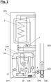
- the brine-water heat pump 101 has the hot water elements, such as the drinking water tank 2, the electric auxiliary heater 7 and the safety temperature limiter 6 and a cable routing duct 1 in the upper part.
- An electrical switch box 3 with a controller circuit board 4 and a connection for the power supply 5 are provided on the front.
- thermodynamic devices that carry the working fluid in the refrigeration circuit, these are the compressor 12, the expansion valve 14, the evaporator 18, the condenser 19 and the 3-way valve 8, plus the pumps for the heat transfer fluids, these are the heating circuit pump 9 and the brine pump 17, as well as the filling and drain valves for the heating circuit 10 and the brine circuit 16.
- thermodynamic devices show the changes due to the security concept.
- the part in which the thermodynamic devices are located is encapsulated by a capsule housing 107 .
- this encapsulation is sealed to the outside, but air can flow in from the outside via an air inlet opening 104 if a negative pressure arises.
- An air duct 103 which forms both the supply air duct and the exhaust air duct, leads from the capsule housing 107 into the installation space, with the air being guided from the capsule housing 107 via an extraction device 109, a conveying fan 105 and an ignition chamber 102 into the air duct 103.
- the escaping working fluid increases the pressure in the capsule housing and the working fluid-air mixture escapes through the extraction device 109 into the ignition chamber 102. If the mixture is ignitable, ignition occurs and the working fluid oxidizes, heating up. It rises in the air duct 103 due to the chimney effect.
- the air access is still closed by the conveying fan 106, the exhaust gas can only escape upwards into the installation room.
- the working fluid is detected in the gas sensor 108.
- the conveying fan 106 is also started to ensure that there is always excess air in the exhaust gas oxidizer.
- the gas sensor can determine the concentrations to regulate the conveying fans 105 and 106 to set an ideal excess air.
- the conveyance fan 106 can also be turned on to cool the ignition chamber by directing a constant flow of air around the outside of the ignition chamber.
- the two conveyor fans must be explosion-proof, and a battery-powered emergency power supply must be set up in the event of a power failure.
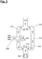
- FIG 3 shows an exemplary embodiment of an exhaust gas oxidation device 110.
- This is equipped with an ignition device 111, which generates ignition sparks at short intervals. If an ignitable mixture flows past the ignition device 111 from the capsule housing 107 via the suction connection 109 , ignition takes place in the ignition chamber 102 . A lot of heat can be generated during this combustion process, so in order to cool the ignition chamber 102, a flow area 112 is provided, the air flow for this is provided by the conveying fan 106.
- the flow area 112 is delimited on the inside of the ignition chamber 102 by one or more inlet grilles 113, one or more protective plates 114 and one or more outlet grilles.
- the openings in the grilles are dimensioned in accordance with international standards for flame arresters.
- the flow control is in 3 shown by arrows.
- a chimney pipe serves as the exhaust gas outlet.
Landscapes
- Engineering & Computer Science (AREA)
- Mechanical Engineering (AREA)
- General Engineering & Computer Science (AREA)
- Chemical & Material Sciences (AREA)
- Combustion & Propulsion (AREA)
- Physics & Mathematics (AREA)
- Thermal Sciences (AREA)
- Environmental & Geological Engineering (AREA)
- Chemical Kinetics & Catalysis (AREA)
- Optics & Photonics (AREA)
- Air Conditioning Control Device (AREA)
- Ventilation (AREA)
- Heat-Exchange Devices With Radiators And Conduit Assemblies (AREA)
Abstract
Description
- Die Erfindung betrifft irreguläre Zustände in Kältekreisen, in denen ein als Kältemittel wirkendes, gefährliches Arbeitsfluid in einem thermodynamischen Kreisprozess, wie zum Beispiel dem Clausius-Rankine-Kreisprozess, geführt wird. Vorwiegend sind dies Wärmepumpen, Klimaanlagen und Kühlgeräte, wie sie in Wohngebäuden gebräuchlich sind. Insbesondere betrifft die Erfindung eine Wärmepumpe, die innerhalb eines Wohngebäudes aufgestellt wird und auch Belüftungszwecke erfüllt.
- Unter Wohngebäuden werden dabei Privathäuser, Miethauskomplexe, Krankenhäuser, Hotelanlagen, Gastronomie und kombinierte Wohn- und Geschäftshäuser verstanden, in denen Menschen dauerhaft leben und arbeiten, im Unterschied zu mobilen Vorrichtungen wie KFZ-Klimaanlagen oder Transportboxen, oder auch Industrieanlagen oder medizintechnischen Geräten. Gemeinsam ist diesen Kreisprozessen, dass sie unter Einsatz von Energie Nutzwärme oder Nutzkälte erzeugen und Wärmeverschiebungssysteme bilden.
- Ein erfolgreiches Beispiel aus dem bekannten Stand der Technik ist das geoTHERM-Plus-System; wie es in der Firmendruckschrift "System geoTHERM", Vaillant GmbH 03/2009, beschrieben ist. Hierbei wird Wärme aus einer Erdbohrung gewonnen, wobei diese Erdbohrung von einem Solekreislauf durchströmt wird, wobei sie Wärme aufnimmt oder abgibt. Die Wärmepumpe selbst wie auch ihre Installationen für die Nutzer werden innerhalb eines Gebäudes aufgestellt, woraus hohe Ansprüche an die Sicherheit folgen.
- Ein weiteres bekanntes System ist das "versoTherm plus" System, wie es in der Firmendruckschrift "versoTherm plus" der Vaillant GmbH 08/2018 beschrieben ist. Solche Systeme bilden den nächstliegenden Stand der Technik.
- Die zum Einsatz kommenden thermodynamischen Kreisprozesse sind seit langem bekannt, ebenso die Sicherheitsprobleme, die bei der Verwendung geeigneter Arbeitsfluide entstehen können. Abgesehen von Wasser sind die bekanntesten damaligen Arbeitsfluide brennbar und giftig. Sie führten im vergangenen Jahrhundert zur Entwicklung der Sicherheitskältemittel, die aus fluorierten Kohlenwasserstoffen bestanden. Es zeigte sich jedoch, dass diese Sicherheitskältemittel die Ozonschicht schädigen, zur Klimaerwärmung führen, und dass ihre sicherheitstechnische Unbedenklichkeit zu konstruktiven Unachtsamkeiten führte. Bis zu 70 % des Umsatzes entfiel auf den Nachfüllbedarf undichter Anlagen und deren Leckageverluste, der hingenommen wurde, solange dies im Einzelfall als wirtschaftlich vertretbar empfunden wurde und Bedarf an Ersatzbeschaffung förderte.
- Der Einsatz dieser Kältemittel wurde aus diesem Grund Restriktionen unterworfen, in der Europäischen Union beispielsweise durch die F-Gas-Verordnung (EU) 517/2014. Dadurch werden praktisch alle ungefährlichen Sicherheitskältemittel verboten und es bleiben nur noch gefährliche Arbeitsfluide und Wasser zur Auswahl. Gefährlich bedeutet in diesem Fall, dass sie entweder giftig sind, wie zum Beispiel Ammoniak, oder entzündlich oder explosiv in Verbindung mit Luftsauerstoff sein können, jedoch kaum umweltschädlich sind.
- Die auftretenden Probleme bei der Sicherheitsauslegung solcher Anlagen werden in der
WO 2015/032905 A1 anschaulich beschrieben. So liegt die untere Zündgrenze von R290 als Arbeitsfluid etwa bei 1,7 Volumenprozent in Luft, was 38 g/m3 in Luft entspricht. Sofern der Kälteprozess in einem ihn umgebenden, hermetisch abgeschlossenen, ansonsten aber luftgefüllten Raum mit dem Arbeitsfluid R290 durchgeführt wird, stellt sich das Problem der Erkennung einer kritischen, explosiven Situation nach einer Störung, bei der das Arbeitsfluid in diesen hermetisch abgeschlossenen Raum austritt. Elektrische Sensoren zur Erkennung kritischer Konzentrationen sind nur schwierig explosionsgeschützt auszuführen, weswegen gerade die Propan-Erkennung durch die Sensoren selbst das Explosionsrisiko erheblich verschärft, ausgenommen hiervon sind Infrarotsensoren. R290 ist auch giftig, bei Inhalation oberhalb einer Konzentration von ca. 2 g/m3 stellen sich narkotische Effekte, Kopfschmerzen und Übelkeit ein. Dies betrifft Personen, die ein erkanntes Problem vor Ort lösen sollen, noch bevor Explosionsgefahr entsteht. - Die
EP 3 106 780 B1 beschreibt eine Absorptionswärmepumpe, die eine Sorptionsstufe enthält. Im Falle einer Leckage saugt ein Gebläse freiwerdendes Kältemittel über ein Bindemittel ab und führt die Reste stromab einem Brenner zu, der als elektrisch betreibene Heizwendel, als Pilotflamme oder als katalytischer Brenner ausgeführt ist. - Die Aufgabe der Erfindung ist daher, eine Vorrichtung und ein Verfahren für eine sichere und effiziente Abluftbehandlung für eine Wärmepumpe bereitzustellen, die in einem Wohngebäude aufgestellt ist, und in der ein linksdrehender thermodynamischer Kreisprozess in einem geschlossenen, hermetisch dichten Arbeitsfluidumlauf mittels eines entzündlichen Arbeitsfluids durchgeführt wird.
- Die Erfindung löst diese Aufgabe zur sicheren Durchführung eines linksdrehenden thermodynamischen Kreisprozesses in einer Wärmepumpe mittels eines gefährlichen Arbeitsfluids, welches in einem geschlossenen, hermetisch dichten Arbeitsfluidumlauf geführt wird, geeignet zur Aufstellung in einem Gebäude, aufweisend
- ein Wärmepumpengehäuse,
- mindestens einen Verdichter für Arbeitsfluid,
- mindestens eine Entspannungseinrichtung für Arbeitsfluid,
- mindestens zwei Wärmeübertrager für Arbeitsfluid mit jeweils mindestens zwei Anschlüssen für Wärmeüberträgerfluide,
- ein Kapselgehäuse innerhalb des Wärmepumpengehäuses, welches alle Apparate und Armaturen umschließt, die von Arbeitsfluid durchströmt werden,
- eine Abgasoxidationsvorrichtung, die mit dem Inneren des Kapselgehäuses verbunden ist,
- ein Fördergebläse für Abluft aus dem Kapselgehäuse in die Abgasoxidationsvorrichtung,
- eine Zuluftöffnung für das Kapselgehäuse,
- einen Zuluftkanal für die Abgasoxidationsvorrichtung aus der Umgebung der Wärmepumpe,
- einen Abluftkanal aus der Abgasoxidationsvorrichtung in die Umgebung der Wärmepumpe.
- Zuluftkanal und Abluftkanal können dabei auch aus einem Stück bestehen. Der Zuluftkanal ist aus Sicherheitsgründen mit einer Rückflusssicherung zu versehen.
- Sollte also eine Leckage auftreten, bewirkt der dabei entstehende Überdruck, dass das Luftgemisch aus dem Kapselgehäuse direkt in die Abgasoxidationsvorrichtung entweicht, wo es unschädlich gemacht wird. Zu Beginn einer Leckage ist die Konzentration des Arbeitsfluids in der Luft im Kapselgehäuse gering, er kann je nach Größe der Leckage aber schnell ansteigen. Davon hängt ab, ob und gegebenenfalls wieviel zusätzliche Luft in die Abgasoxidationsvorrichtung zugeführt werden muss.
- Eine Ausgestaltung der Erfindung sieht daher vor, dass ein Gassensor im Kapselgehäuse vorgesehen wird, der das Fördergebläse für Abluft einschaltet, falls gasförmiges Arbeitsfluid erkannt wird. Eine verbesserte Ausgestaltung sieht vor, dass eine Konzentrationsmessung für gasförmiges Arbeitsfluid im Kapselgehäuse vorgenommen wird und das Fördergebläse für Abluft entsprechend der Konzentration an Arbeitsfluid oder innerhalb eines Einstellbereichs für Sauerstoffüberschuss (Lambda-Fenster) geregelt wird.
- Weitere Ausgestaltungen betreffen die Abgasoxidationsvorrichtung. In einer Ausgestaltung wird vorgesehen, dass die Abgasoxidationsvorrichtung
- eine Zündung,
- eine Zündkammer und
- Gitter mit Flammendurchschlagschutz aufweist.
- Anstelle von Gittern können auch Netze mit entsprechenden Maschenweiten oder poröse Keramikkörper verwendet werden. Die erforderliche Spaltweite ist die des "Quenching-Durchmessers", was der Grenzschicht für unverbranntes Gas entlang einer kalten Wandfläche entspricht.
- In einer Ausgestaltung ist vorgesehen, dass in dem Luftkanal für Spülluft ein Fördergebläse vorgesehen wird, welches explosionsgeschützt ausgeführt ist. Das Kapselgehäuse muss hierfür über einen Luftzugang verfügen, der entweder im Luftkanal integriert ist oder der als Öffnungen im Kapselgehäuse ausgeführt wird, durch welche Luft einströmen, aber nicht ausströmen kann, beispielsweise durch Jalousieklappen, die nur in eine Richtung zu öffnen sind.
- Alternativ kann die Regelung der Verbrennung auch über einen Venturi erfolgen, wobei der Anschluss an die Unterdruckkammer des Wärmepumpengehäuses den Gasanschluss darstellt, so dass dieser Aufbau mit nur einem Spülluftgebläse betrieben wird. Die Regelung der Medien-Zuführung aus der Wärmepumpe erfolgt dann über eine variable Blendenöffnungsregelung, die mit dem Gassensor realisiert wird.
- Weitere Ausgestaltungen betreffen die Abluftoxidation. Dies erfolgt vorzugsweise katalytisch. Hierzu wird in die Zündkammer ein Katalysator eingesetzt, dieser Katalysator kann auch eine poröse Keramik sein, die gleichzeitig als Flammschutzgitter wirkt.
- Wird beispielsweise R290 mit der Hauptkomponente Propan als Arbeitsfluid genutzt, findet ab 500 °C eine Oxidation oder Dehydrogenisierung statt. Bei dieser Oxidation entsteht ein Alkohol. Dieser Alkohol ist wasserlöslich und ist bei der geringen Konzentration ein geringeres Problem als Propan. Bei der Dehydrogenisierung entsteht Propen. Das kann aufgrund der Doppelbindung besser abgebaut werden. Das heißt, die Abgasoxidation kann auch gestuft erfolgen, indem zunächst eine katalytische Umsetzung bei geringerer Temperatur erfolgt und erst nachfolgend eine weitere Totaloxidation zu CO2 und Wasser vorgenommen wird.
- Auf diese Weise kann mit Co(III)-CF3COOH und/oder Pt/SrTiO3 als Katalysatoren in einer ersten Stufe eine Oxidation von Propan bei 150-180 °C durchgeführt werden. In einer zweiten Stufe wird mit dem Katalysator Ru/CeO2 nachfolgend eine Totaloxidation bei 150 °C erreicht. Es ist bei dieser katalytischen Oxidation nicht erforderlich, das gesamte Arbeitsfluid im Abgas zu oxidieren, es muss lediglich gesichert sein, dass das Abgas hinter der Oxidation deutlich unterhalb der unteren Zündgrenze für das betreffende Arbeitsfluid liegt, denn diese wird durch die weitere Verdünnung mit Umgebungsluft nicht mehr unterschritten.
- Weitere Ausgestaltungen betreffen die Zündung. Diese kann mittels einer Glühkerze, eines Piezo-Elements oder mittels UV-Licht erfolgen. Die Zündung hängt auch davon ab, ob ein Katalysator verwendet wird, sofern ein Katalysator auf einer porösen Festkeramik zum Einsatz kommt, kann die Zündung auch mittels UV-Licht, welches auf diesen Festkörper gerichtet ist, erfolgen. Auch ein UV-Laser kann dazu eingesetzt werden.
- Je nach detektierter Gaskonzentration kann entweder nur das Fördergebläse zur Zündkammer aus dem Kapselgehäuse aktiviert werden, was bei kleineren Konzentrationen vorzunehmen ist, oder es wird zusätzlich die Zwangsbelüftung mittels des Fördergebläses am Fuß des Luftkanals aktiviert, was bei größeren Konzentrationen an Arbeitsfluid oder schnellen Konzentrationsanstiegen zu erfolgen hat, um einen ausreichenden Luftüberschuss zu gewährleisten. Bei sehr kleinen Konzentrationen, die kein zündfähiges Gemisch hervorrufen, kann auf die Zündung in der Zündkammer auch verzichtet werden, da durch die nachfolgende Verdünnung mit weiterer Luft sich auch in der Folge kein zündfähiges Gemisch einstellen kann.
- Wichtig ist aber immer, dass die Dichtigkeit des Reaktionsraumes auf Dauer sichergestellt ist.
- Die Erfindung wird nachfolgend näher erläutert. Dabei zeigen
-
Fig. 1 schematisch eine Wärmepumpe nach dem Stand der Technik, die in einem Wohngebäude steht, -
Fig. 2 dieselbe Wärmepumpe mit der entsprechenden Sicherheitsausstattung und -
Fig.3 ein Beispiel einer Abgasoxidationsvorrichtung. -
Fig. 1 zeigt ein Wohngebäude 100, welches mit einer Sole-Wasser-Wärmepumpe 101, die auch als Heißwassergerät genutzt wird, ausgestattet ist. Die Sole-Wasser-Wärmepumpe 101 weist im oberen Teil die Warmwasserelemente, wie etwa den Trinkwasserspeicher 2, die elektrische Zusatzheizung 7 sowie den Sicherheitstemperaturbegrenzer 6 und einen Leitungsführungskanal 1 auf. An der Vorderfront sind ein Elektroschaltkasten 3 mit einer Reglerplatine 4 und ein Anschluss für die Spannungsversorgung 5 vorgesehen. - Im unteren Teil sind die thermodynamischen Apparate angeordnet, die das Arbeitsfluid im Kältekreis führen, dies sind der Kompressor 12, das Expansionsventil 14, der Verdampfer 18, der Verflüssiger 19 sowie das 3-Wege-Ventil 8, hinzu kommen die Pumpen für die Wärmeträgerfluide, dies sind die Heizkreispumpe 9 und die Solepumpe 17, sowie die Füll- und Entleerventile für den Heizkreislauf 10 und den Solekreislauf 16.
- Es ist dabei frei wählbar, ob diese Anordnungen in der oben beschriebenen Weise vorgenommen werden, oder ob der Warmwasserteil und der Kältekreis nebeneinander oder genau andersrum übereinander angeordnet werden. Im Bodenbereich befinden sich das Typenschild 11, die Griffmulden 13 und die Kondensatwanne 15.
-
Fig. 2 zeigt die Änderungen durch das Sicherheitskonzept. Als erstes wird der Teil, in dem sich die thermodynamischen Apparate befinden, durch ein Kapselgehäuse 107 gekapselt. Diese Kapselung ist einerseits nach außen hin dicht, es kann jedoch Luft von außen über eine Zuluftöffnung 104 einströmen, wenn ein Unterdruck entsteht. - Vom Kapselgehäuse 107 führt ein Luftkanal 103, der sowohl den Zuluftkanal als auch den Abluftkanal bildet, in den Aufstellungsraum, wobei die Luft aus dem Kapselgehäuse 107 über eine Abzugsvorrichtung 109, ein Fördergebläse 105 und eine Zündkammer 102 in den Luftkanal 103 geführt wird. Sobald sich eine Leckage ergibt, steigt durch das austretende Arbeitsfluid der Druck im Kapselgehäuse und das Arbeitsfluid-Luftgemisch entweicht durch die Abzugsvorrichtung 109 in die Zündkammer 102. Wenn das Gemisch zündfähig ist, erfolgt eine Zündung und das Arbeitsfluid oxidiert, wobei es sich erwärmt. Durch die Kaminwirkung steigt es im Luftkanal 103 auf. Zu diesem Zeitpunkt ist der Luftzugang durch das Fördergebläse 106 noch verschlossen, das Abgas kann nur nach oben in den Aufstellungsraum entweichen.
- Gleichzeitig erfolgt die Detektion des Arbeitsfluids im Gassensor 108. Dadurch wird das Fördergebläse 105 gestartet und die Menge der Luft, die aus dem Kapselgehäuse 107 abgezogen wird, steigt derart, dass über die Zuluftöffnung 104 Luft nachströmt, die der Spülung des Kapselgehäuses dient. Falls die Konzentration, die vom Gassensor 108 gemessen wird, danach immer noch ansteigt, wird auch das Fördergebläse 106 gestartet, damit gewährleistet ist, dass in der Abgasoxidationsvorrichtung immer ein Luftüberschuss vorhanden ist. Je nachdem, wie fein der Gassensor die Konzentrationen ermitteln kann, ist eine Regelung der Fördergebläse 105 und 106 zur Einstellung eines idealen Luftüberschusses vorzunehmen.
- Das Fördergebläse 106 kann auch eingeschaltet werden, um die Zündkammer zu kühlen, indem ein ständiger Luftstrom außen um die Zündkammer herumgeführt wird. Die beiden Fördergebläse sind explosionsgeschützt auszuführen, für den Fall eines Stromausfalls ist eine akkubetriebene Notstromversorgung einzurichten.
-
Fig. 3 zeigt eine beispielhafte Ausführungsform einer Abgasoxidationsvorrichtung 110. Diese ist ausgestattet mit einer Zündvorrichtung 111, die in kurzen Abständen Zündfunken erzeugt. Sofern über den Sauganschluss 109 aus dem Kapselgehäuse 107 ein zündfähiges Gemisch an der Zündvorrichtung 111 vorbeiströmt, findet eine Zündung in der Zündkammer 102 statt. Bei diesem Verbrennungsvorgang kann viel Wärme entstehen, um die Zündkammer 102 zu kühlen, wird daher ein Umströmungsbereich 112 vorgesehen, den Luftstrom hierfür liefert das Fördergebläse 106. - Der Umströmungsbereich 112 wird innen von der Zündkammer 102 begrenzt durch ein oder mehrere Einlassgitter 113, ein oder mehrere Schutzbleche 114 und ein oder mehrere Auslassgitter. Um ein Durchschlagen von Flammen in Form einer Deflagration zu verhindern, sind die Öffnungen der Gitter entsprechend internationaler Normen für Flammendurchschlagsicherungen dimensioniert. Die Strömungsführung wird dabei in
Fig. 3 durch Pfeile gezeigt. Als Abgasauslass dient ein Kaminrohr. -
- 1
- Leitungsführungskanal
- 2
- Trinkwasserspeicher
- 3
- Elektroschaltkasten
- 4
- Reglerplatine
- 5
- Anschluss Spannungsversorgung
- 6
- Sicherheitstemperaturbegrenzer STB der Zusatzheizung
- 7
- Elektrische Zusatzheizung
- 8
- 3-Wege-Ventil
- 9
- Heizkreispumpe
- 10
- Füll-und Entleerventil Heizungskreislauf
- 11
- Typenschild
- 12
- Kompressor
- 13
- Griffmulden
- 14
- Expansionsventil
- 15
- Kondensatwanne
- 16
- Füll- und Entleerventil Solekreislauf
- 17
- Solepumpe
- 18
- Verdampfer
- 19
- Verflüssiger
- 100
- Wohngebäude
- 101
- Wärmepumpe
- 102
- Zündkammer
- 103
- Luftkanal / Zuluftkanal / Abluftkanal
- 104
- Zuluftöffnung
- 105
- Fördergebläse
- 106
- Fördergebläse
- 107
- Kapselgehäuse
- 108
- Gassensor
- 109
- Sauganschluss
- 110
- Abgasoxidationsvorrichtung
- 111
- Zündvorrichtung
- 112
- Umströmungsbereich
- 113
- Einlassgitter
- 114
- Schutzblech
- 115
- Auslassgitter
- 116
- Abgasauslass
Claims (16)
- Wärmepumpe zur sicheren Durchführung eines linksdrehenden thermodynamischen Kreisprozesses mittels eines gefährlichen Arbeitsfluids, welches in einem geschlossenen, hermetisch dichten Arbeitsfluidumlauf geführt wird, geeignet zur Aufstellung in einem Gebäude, aufweisend- ein Wärmepumpengehäuse,- mindestens einen Verdichter für Arbeitsfluid,- mindestens eine Entspannungseinrichtung für Arbeitsfluid,- mindestens zwei Wärmeübertrager für Arbeitsfluid mit jeweils mindestens zwei Anschlüssen für Wärmeüberträgerfluide,- ein Kapselgehäuse (107) innerhalb des Wärmepumpengehäuses, welches alle Apparate und Armaturen umschließt, die von Arbeitsfluid durchströmt werden,
dadurch gekennzeichnet, dass- eine Abgasoxidationsvorrichtung, die mit dem Inneren des Kapselgehäuses verbunden ist,- mindestens ein Fördergebläse (105, 106) für Abluft aus dem Kapselgehäuse in die Abgasoxidationsvorrichtung,- eine Zuluftöffnung (104) für das Kapselgehäuse,- ein Zuluftkanal für die Abgasoxidationsvorrichtung aus der Umgebung der Wärmepumpe, und- ein Abluftkanal aus der Abgasoxidationsvorrichtung in die Umgebung der Wärmepumpe vorgesehen wird. - Wärmepumpe nach Anspruch 1, dadurch gekennzeichnet, dass Zuluftkanal und Abluftkanal aus einem Stück bestehen.
- Wärmepumpe nach einem der Ansprüche 1 oder 2, dadurch gekennzeichnet, dass der Zuluftkanal mit einer Rückflusssicherung versehen ist.
- Wärmepumpe nach einem der Ansprüche 1 bis 3, dadurch gekennzeichnet, dass in dem Luftkanal (103) für Spülluft ein Fördergebläse (106) vorgesehen wird, welches explosionsgeschützt ausgeführt ist.
- Wärmepumpe nach einem der Ansprüche 1 bis 4, dadurch gekennzeichnet, dass mindestens ein Gassensor (108) im Kapselgehäuse (107) angeordnet wird, bei dessen Alarm die Zwangsbelüftung des Kapselgehäuses (107) aktiviert wird.
- Wärmepumpe nach Anspruch 5, dadurch gekennzeichnet, dass der Gassensor eine Konzentrationsmessung des gasförmigen Arbeitsfluids vornimmt und das damit Fördergebläse so geregelt wird, dass ein vorgebbarer Luftüberschuss eingestellt wird.
- Wärmepumpe nach einem der Ansprüche 1 bis 6, dadurch gekennzeichnet, dass die Abgasoxidationsvorrichtung eine Zündung, eine Zündkammer und Gitter oder Netze oder poröse Keramikkörper, jeweils mit Flammendurchschlagschutz, aufweist.
- Wärmepumpe nach einem der Ansprüche 1 bis 7, dadurch gekennzeichnet, dass in dem Luftkanal für Spülluft ein Fördergebläse vorgesehen wird, welches explosionsgeschützt ausgeführt ist.
- Wärmepumpe nach einem der Ansprüche 1 bis 8, dadurch gekennzeichnet, dass in die Zündkammer ein Katalysator eingesetzt wird.
- Wärmepumpe nach Anspruch 9, dadurch gekennzeichnet, dass der Oxidationskatalysator auf Gittern oder Netzen oder einer porösen Keramik aufgebracht wird.
- Wärmepumpe nach einem der Ansprüche 9 oder 10, dadurch gekennzeichnet, dass als Katalysatoren C0(III)-CF3COOH und/oder Pt/SrTiO3 eingesetzt werden.
- Wärmepumpe nach einem der Ansprüche 9 oder 10, dadurch gekennzeichnet, dass als Katalysator Ru/CeO2 eingesetzt wird.
- Wärmepumpe nach einem der Ansprüche 9 bis 12, dadurch gekennzeichnet, dass zwei katalytische Oxidationsstufen eingesetzt werden, von denen in Strömungsrichtung die erste Oxidationsstufe Katalysatoren aus Co(III)-CF3COOH und/oder Pt/SrTiO3 aufweisen und die zweite Oxidationsstufe einen Katalysator aus Ru/CeO2 aufweist.
- Wärmepumpe nach Anspruch 1, dadurch gekennzeichnet, dass die Zündung mittels einer Glühkerze, eines Piezo-Elements oder mittels UV-Licht erfolgt.
- Wärmepumpe nach einem der Ansprüche 9 bis 14, dadurch gekennzeichnet, dass die Zündung durch Bestrahlung von UV-Licht auf den Katalysator erfolgt.
- Wärmepumpe nach Anspruch 15, dadurch gekennzeichnet, dass die UV-Strahlungsquelle ein UV-Laser ist.
Applications Claiming Priority (1)
| Application Number | Priority Date | Filing Date | Title |
|---|---|---|---|
| DE102020120615.1A DE102020120615A1 (de) | 2020-08-05 | 2020-08-05 | Aktive Abluftbehandlung für eine Wärmepumpe |
Publications (2)
| Publication Number | Publication Date |
|---|---|
| EP3951282A1 true EP3951282A1 (de) | 2022-02-09 |
| EP3951282B1 EP3951282B1 (de) | 2024-08-07 |
Family
ID=77050898
Family Applications (1)
| Application Number | Title | Priority Date | Filing Date |
|---|---|---|---|
| EP21187653.7A Active EP3951282B1 (de) | 2020-08-05 | 2021-07-26 | Aktive abluftbehandlung für eine wärmepumpe |
Country Status (2)
| Country | Link |
|---|---|
| EP (1) | EP3951282B1 (de) |
| DE (1) | DE102020120615A1 (de) |
Cited By (1)
| Publication number | Priority date | Publication date | Assignee | Title |
|---|---|---|---|---|
| WO2024231035A1 (de) * | 2023-05-10 | 2024-11-14 | Zf Friedrichshafen Ag | Sicherheitsvorrichtung für eine mit einem entzündbaren kältemittel, insbesondere propan betriebene wärmepumpe, sicherheitssystem und fahrzeug |
Families Citing this family (3)
| Publication number | Priority date | Publication date | Assignee | Title |
|---|---|---|---|---|
| WO2021037308A1 (de) * | 2019-08-27 | 2021-03-04 | Faiveley Transport Leipzig Gmbh & Co. Kg | Klimaanlage für ein schienenfahrzeug (überdruck im e-kasten) |
| DE102021213213A1 (de) | 2021-11-24 | 2023-05-25 | Robert Bosch Gesellschaft mit beschränkter Haftung | Wärmepumpenmodul mit Explosionsschutzvorrichtung |
| DE102023135222A1 (de) * | 2023-12-14 | 2025-06-18 | Stiebel Eltron Gmbh & Co. Kg | Innenraum-Wärmepumpe, Verfahren zum Betreiben einer Innenraum-Wärmepumpe, und Steuereinheit für eine Solche |
Citations (5)
| Publication number | Priority date | Publication date | Assignee | Title |
|---|---|---|---|---|
| WO2003010473A1 (fr) * | 2001-07-26 | 2003-02-06 | Climastar Sa | Pompe a chaleur dispositif de ventilation de securite |
| WO2015032905A1 (de) | 2013-09-05 | 2015-03-12 | Holger König | Verfahren zur verhinderung einer leckage aus einem behälter und ein behälter mit leckagesicherung |
| EP3106780A1 (de) * | 2015-06-17 | 2016-12-21 | Vaillant GmbH | Wärmepumpenanlage |
| US20190128565A1 (en) * | 2017-10-30 | 2019-05-02 | Rheem Manufacturing Company | Hybrid water heater |
| DE102018109646A1 (de) * | 2018-04-23 | 2019-10-24 | Vaillant Gmbh | Fluidsorption |
-
2020
- 2020-08-05 DE DE102020120615.1A patent/DE102020120615A1/de not_active Withdrawn
-
2021
- 2021-07-26 EP EP21187653.7A patent/EP3951282B1/de active Active
Patent Citations (6)
| Publication number | Priority date | Publication date | Assignee | Title |
|---|---|---|---|---|
| WO2003010473A1 (fr) * | 2001-07-26 | 2003-02-06 | Climastar Sa | Pompe a chaleur dispositif de ventilation de securite |
| WO2015032905A1 (de) | 2013-09-05 | 2015-03-12 | Holger König | Verfahren zur verhinderung einer leckage aus einem behälter und ein behälter mit leckagesicherung |
| EP3106780A1 (de) * | 2015-06-17 | 2016-12-21 | Vaillant GmbH | Wärmepumpenanlage |
| EP3106780B1 (de) | 2015-06-17 | 2017-11-22 | Vaillant GmbH | Wärmepumpenanlage |
| US20190128565A1 (en) * | 2017-10-30 | 2019-05-02 | Rheem Manufacturing Company | Hybrid water heater |
| DE102018109646A1 (de) * | 2018-04-23 | 2019-10-24 | Vaillant Gmbh | Fluidsorption |
Non-Patent Citations (2)
| Title |
|---|
| "System geoTHERM", March 2009, VAILLANT GMBH |
| "versoTherm plus", August 2018, VAILLANT GMBH |
Cited By (1)
| Publication number | Priority date | Publication date | Assignee | Title |
|---|---|---|---|---|
| WO2024231035A1 (de) * | 2023-05-10 | 2024-11-14 | Zf Friedrichshafen Ag | Sicherheitsvorrichtung für eine mit einem entzündbaren kältemittel, insbesondere propan betriebene wärmepumpe, sicherheitssystem und fahrzeug |
Also Published As
| Publication number | Publication date |
|---|---|
| DE102020120615A1 (de) | 2022-02-10 |
| EP3951282B1 (de) | 2024-08-07 |
Similar Documents
| Publication | Publication Date | Title |
|---|---|---|
| EP3951282B1 (de) | Aktive abluftbehandlung für eine wärmepumpe | |
| EP3792572B1 (de) | Sicherheitsspülvorrichtung für eine wärmepumpe | |
| EP3486582B1 (de) | Vorrichtung zur leckageerkennung mittels adsorber | |
| EP3940314B1 (de) | Sicherheitsspülvorrichtung für eine wärmepumpe | |
| DE69926291T2 (de) | Klimaanlage | |
| EP3578895B1 (de) | Vorrichtung und verfahren für eine sichere und energiesparende spülung eines gehäuses | |
| EP3748257B1 (de) | Vorrichtung zur sicheren durchführung eines linksdrehenden thermodynamischen kreisprozesses mittels eines entzündlichen arbeitsfluids mit der verwendung von fluidadsoprtion | |
| EP4008979B1 (de) | Vorrichtung zur sicheren durchführung eines linksdrehenden thermodynamischen kreisprozesses | |
| DE102019121496A1 (de) | Sicherheitsspülvorrichtung für eine Wärmepumpe | |
| EP3543629B1 (de) | Leckagedichtes gehäuse für einen kreisprozess | |
| EP3581861A2 (de) | Fluidsorption | |
| EP3486564B1 (de) | VORRICHTUNG ZUR SICHEREN DURCHFÜHRUNG EINES LINKSDREHENDEN THERMODYNAMISCHEN CLAUSIUS-RANKINE PROZESS
BASIEREND AUF ARBEITSFLUIDADSORPTION MIT INERTGASVERDRÄNGUNG | |
| EP3486583B1 (de) | Kältekreis mit leckagesicherung | |
| EP4575332A1 (de) | Gekapselter adapter für eine split-wärmepumpe | |
| DE102021213213A1 (de) | Wärmepumpenmodul mit Explosionsschutzvorrichtung | |
| EP3293460B1 (de) | Anlage zur bereitstellung von wärmeenergie und/oder elektrischem strom | |
| EP3486575B1 (de) | Vorrichtung und verfahren zum sicherheitsablass von arbeitsfluid | |
| EP3657104A1 (de) | Formteile für wärmepumpen | |
| EP1175247B1 (de) | Lebensrettungssystem für umschlossene räume, insbesondere tunnel | |
| EP2315977A2 (de) | Heizmodul zur integration in einen rohbau eines hauses | |
| EP3712531A1 (de) | Sicherheitsspülvorrichtung für eine wärmepumpe | |
| DE102019101111A1 (de) | Aufbau zur Trocknung eines Bauteils eines Gebäudes | |
| DE2655881A1 (de) | Verfahren zum thermischen verbrennen von abgasen und nachbrennanlage zu dessen durchfuehrung | |
| DE102021214758A1 (de) | Klimatisierungseinrichtung, System und Verfahren zum Betrieb der Klimatisierungseinrichtung | |
| EP3719416A1 (de) | Wärmepumpen-kreisprozesses mit einem entzündlichen arbeitsfluid |
Legal Events
| Date | Code | Title | Description |
|---|---|---|---|
| PUAI | Public reference made under article 153(3) epc to a published international application that has entered the european phase |
Free format text: ORIGINAL CODE: 0009012 |
|
| STAA | Information on the status of an ep patent application or granted ep patent |
Free format text: STATUS: THE APPLICATION HAS BEEN PUBLISHED |
|
| AK | Designated contracting states |
Kind code of ref document: A1 Designated state(s): AL AT BE BG CH CY CZ DE DK EE ES FI FR GB GR HR HU IE IS IT LI LT LU LV MC MK MT NL NO PL PT RO RS SE SI SK SM TR |
|
| STAA | Information on the status of an ep patent application or granted ep patent |
Free format text: STATUS: REQUEST FOR EXAMINATION WAS MADE |
|
| 17P | Request for examination filed |
Effective date: 20220804 |
|
| RBV | Designated contracting states (corrected) |
Designated state(s): AL AT BE BG CH CY CZ DE DK EE ES FI FR GB GR HR HU IE IS IT LI LT LU LV MC MK MT NL NO PL PT RO RS SE SI SK SM TR |
|
| REG | Reference to a national code |
Ref country code: DE Ref legal event code: R079 Ipc: F23D0014820000 Ref country code: DE Ref legal event code: R079 Ref document number: 502021004659 Country of ref document: DE Free format text: PREVIOUS MAIN CLASS: F24H0004040000 Ipc: F23D0014820000 |
|
| GRAP | Despatch of communication of intention to grant a patent |
Free format text: ORIGINAL CODE: EPIDOSNIGR1 |
|
| STAA | Information on the status of an ep patent application or granted ep patent |
Free format text: STATUS: GRANT OF PATENT IS INTENDED |
|
| RIC1 | Information provided on ipc code assigned before grant |
Ipc: F24H 15/12 20220101ALI20240214BHEP Ipc: F25B 30/02 20060101ALI20240214BHEP Ipc: F24H 9/20 20220101ALI20240214BHEP Ipc: F24H 9/02 20060101ALI20240214BHEP Ipc: F24H 4/04 20060101ALI20240214BHEP Ipc: F25B 49/00 20060101ALI20240214BHEP Ipc: F25B 25/00 20060101ALI20240214BHEP Ipc: F25B 13/00 20060101ALI20240214BHEP Ipc: F23Q 13/00 20060101ALI20240214BHEP Ipc: F23G 7/07 20060101ALI20240214BHEP Ipc: F23D 14/82 20060101AFI20240214BHEP |
|
| INTG | Intention to grant announced |
Effective date: 20240306 |
|
| GRAS | Grant fee paid |
Free format text: ORIGINAL CODE: EPIDOSNIGR3 |
|
| GRAA | (expected) grant |
Free format text: ORIGINAL CODE: 0009210 |
|
| STAA | Information on the status of an ep patent application or granted ep patent |
Free format text: STATUS: THE PATENT HAS BEEN GRANTED |
|
| AK | Designated contracting states |
Kind code of ref document: B1 Designated state(s): AL AT BE BG CH CY CZ DE DK EE ES FI FR GB GR HR HU IE IS IT LI LT LU LV MC MK MT NL NO PL PT RO RS SE SI SK SM TR |
|
| REG | Reference to a national code |
Ref country code: GB Ref legal event code: FG4D Free format text: NOT ENGLISH |
|
| REG | Reference to a national code |
Ref country code: CH Ref legal event code: EP |
|
| REG | Reference to a national code |
Ref country code: IE Ref legal event code: FG4D Free format text: LANGUAGE OF EP DOCUMENT: GERMAN |
|
| REG | Reference to a national code |
Ref country code: DE Ref legal event code: R096 Ref document number: 502021004659 Country of ref document: DE |
|
| REG | Reference to a national code |
Ref country code: LT Ref legal event code: MG9D |
|
| REG | Reference to a national code |
Ref country code: NL Ref legal event code: MP Effective date: 20240807 |
|
| PG25 | Lapsed in a contracting state [announced via postgrant information from national office to epo] |
Ref country code: NO Free format text: LAPSE BECAUSE OF FAILURE TO SUBMIT A TRANSLATION OF THE DESCRIPTION OR TO PAY THE FEE WITHIN THE PRESCRIBED TIME-LIMIT Effective date: 20241107 |
|
| PG25 | Lapsed in a contracting state [announced via postgrant information from national office to epo] |
Ref country code: NL Free format text: LAPSE BECAUSE OF FAILURE TO SUBMIT A TRANSLATION OF THE DESCRIPTION OR TO PAY THE FEE WITHIN THE PRESCRIBED TIME-LIMIT Effective date: 20240807 Ref country code: PL Free format text: LAPSE BECAUSE OF FAILURE TO SUBMIT A TRANSLATION OF THE DESCRIPTION OR TO PAY THE FEE WITHIN THE PRESCRIBED TIME-LIMIT Effective date: 20240807 Ref country code: GR Free format text: LAPSE BECAUSE OF FAILURE TO SUBMIT A TRANSLATION OF THE DESCRIPTION OR TO PAY THE FEE WITHIN THE PRESCRIBED TIME-LIMIT Effective date: 20241108 Ref country code: PT Free format text: LAPSE BECAUSE OF FAILURE TO SUBMIT A TRANSLATION OF THE DESCRIPTION OR TO PAY THE FEE WITHIN THE PRESCRIBED TIME-LIMIT Effective date: 20241209 Ref country code: FI Free format text: LAPSE BECAUSE OF FAILURE TO SUBMIT A TRANSLATION OF THE DESCRIPTION OR TO PAY THE FEE WITHIN THE PRESCRIBED TIME-LIMIT Effective date: 20240807 |
|
| PG25 | Lapsed in a contracting state [announced via postgrant information from national office to epo] |
Ref country code: BG Free format text: LAPSE BECAUSE OF FAILURE TO SUBMIT A TRANSLATION OF THE DESCRIPTION OR TO PAY THE FEE WITHIN THE PRESCRIBED TIME-LIMIT Effective date: 20240807 |
|
| PG25 | Lapsed in a contracting state [announced via postgrant information from national office to epo] |
Ref country code: LV Free format text: LAPSE BECAUSE OF FAILURE TO SUBMIT A TRANSLATION OF THE DESCRIPTION OR TO PAY THE FEE WITHIN THE PRESCRIBED TIME-LIMIT Effective date: 20240807 |
|
| PG25 | Lapsed in a contracting state [announced via postgrant information from national office to epo] |
Ref country code: IS Free format text: LAPSE BECAUSE OF FAILURE TO SUBMIT A TRANSLATION OF THE DESCRIPTION OR TO PAY THE FEE WITHIN THE PRESCRIBED TIME-LIMIT Effective date: 20241207 |
|
| PG25 | Lapsed in a contracting state [announced via postgrant information from national office to epo] |
Ref country code: HR Free format text: LAPSE BECAUSE OF FAILURE TO SUBMIT A TRANSLATION OF THE DESCRIPTION OR TO PAY THE FEE WITHIN THE PRESCRIBED TIME-LIMIT Effective date: 20240807 |
|
| PG25 | Lapsed in a contracting state [announced via postgrant information from national office to epo] |
Ref country code: RS Free format text: LAPSE BECAUSE OF FAILURE TO SUBMIT A TRANSLATION OF THE DESCRIPTION OR TO PAY THE FEE WITHIN THE PRESCRIBED TIME-LIMIT Effective date: 20241107 Ref country code: ES Free format text: LAPSE BECAUSE OF FAILURE TO SUBMIT A TRANSLATION OF THE DESCRIPTION OR TO PAY THE FEE WITHIN THE PRESCRIBED TIME-LIMIT Effective date: 20240807 |
|
| PG25 | Lapsed in a contracting state [announced via postgrant information from national office to epo] |
Ref country code: RS Free format text: LAPSE BECAUSE OF FAILURE TO SUBMIT A TRANSLATION OF THE DESCRIPTION OR TO PAY THE FEE WITHIN THE PRESCRIBED TIME-LIMIT Effective date: 20241107 Ref country code: PT Free format text: LAPSE BECAUSE OF FAILURE TO SUBMIT A TRANSLATION OF THE DESCRIPTION OR TO PAY THE FEE WITHIN THE PRESCRIBED TIME-LIMIT Effective date: 20241209 Ref country code: PL Free format text: LAPSE BECAUSE OF FAILURE TO SUBMIT A TRANSLATION OF THE DESCRIPTION OR TO PAY THE FEE WITHIN THE PRESCRIBED TIME-LIMIT Effective date: 20240807 Ref country code: NO Free format text: LAPSE BECAUSE OF FAILURE TO SUBMIT A TRANSLATION OF THE DESCRIPTION OR TO PAY THE FEE WITHIN THE PRESCRIBED TIME-LIMIT Effective date: 20241107 Ref country code: NL Free format text: LAPSE BECAUSE OF FAILURE TO SUBMIT A TRANSLATION OF THE DESCRIPTION OR TO PAY THE FEE WITHIN THE PRESCRIBED TIME-LIMIT Effective date: 20240807 Ref country code: LV Free format text: LAPSE BECAUSE OF FAILURE TO SUBMIT A TRANSLATION OF THE DESCRIPTION OR TO PAY THE FEE WITHIN THE PRESCRIBED TIME-LIMIT Effective date: 20240807 Ref country code: IS Free format text: LAPSE BECAUSE OF FAILURE TO SUBMIT A TRANSLATION OF THE DESCRIPTION OR TO PAY THE FEE WITHIN THE PRESCRIBED TIME-LIMIT Effective date: 20241207 Ref country code: HR Free format text: LAPSE BECAUSE OF FAILURE TO SUBMIT A TRANSLATION OF THE DESCRIPTION OR TO PAY THE FEE WITHIN THE PRESCRIBED TIME-LIMIT Effective date: 20240807 Ref country code: GR Free format text: LAPSE BECAUSE OF FAILURE TO SUBMIT A TRANSLATION OF THE DESCRIPTION OR TO PAY THE FEE WITHIN THE PRESCRIBED TIME-LIMIT Effective date: 20241108 Ref country code: FI Free format text: LAPSE BECAUSE OF FAILURE TO SUBMIT A TRANSLATION OF THE DESCRIPTION OR TO PAY THE FEE WITHIN THE PRESCRIBED TIME-LIMIT Effective date: 20240807 Ref country code: ES Free format text: LAPSE BECAUSE OF FAILURE TO SUBMIT A TRANSLATION OF THE DESCRIPTION OR TO PAY THE FEE WITHIN THE PRESCRIBED TIME-LIMIT Effective date: 20240807 Ref country code: BG Free format text: LAPSE BECAUSE OF FAILURE TO SUBMIT A TRANSLATION OF THE DESCRIPTION OR TO PAY THE FEE WITHIN THE PRESCRIBED TIME-LIMIT Effective date: 20240807 |
|
| PG25 | Lapsed in a contracting state [announced via postgrant information from national office to epo] |
Ref country code: SM Free format text: LAPSE BECAUSE OF FAILURE TO SUBMIT A TRANSLATION OF THE DESCRIPTION OR TO PAY THE FEE WITHIN THE PRESCRIBED TIME-LIMIT Effective date: 20240807 Ref country code: DK Free format text: LAPSE BECAUSE OF FAILURE TO SUBMIT A TRANSLATION OF THE DESCRIPTION OR TO PAY THE FEE WITHIN THE PRESCRIBED TIME-LIMIT Effective date: 20240807 |
|
| PG25 | Lapsed in a contracting state [announced via postgrant information from national office to epo] |
Ref country code: EE Free format text: LAPSE BECAUSE OF FAILURE TO SUBMIT A TRANSLATION OF THE DESCRIPTION OR TO PAY THE FEE WITHIN THE PRESCRIBED TIME-LIMIT Effective date: 20240807 |
|
| PG25 | Lapsed in a contracting state [announced via postgrant information from national office to epo] |
Ref country code: CZ Free format text: LAPSE BECAUSE OF FAILURE TO SUBMIT A TRANSLATION OF THE DESCRIPTION OR TO PAY THE FEE WITHIN THE PRESCRIBED TIME-LIMIT Effective date: 20240807 |
|
| PG25 | Lapsed in a contracting state [announced via postgrant information from national office to epo] |
Ref country code: SK Free format text: LAPSE BECAUSE OF FAILURE TO SUBMIT A TRANSLATION OF THE DESCRIPTION OR TO PAY THE FEE WITHIN THE PRESCRIBED TIME-LIMIT Effective date: 20240807 |
|
| REG | Reference to a national code |
Ref country code: DE Ref legal event code: R097 Ref document number: 502021004659 Country of ref document: DE |
|
| PLBE | No opposition filed within time limit |
Free format text: ORIGINAL CODE: 0009261 |
|
| STAA | Information on the status of an ep patent application or granted ep patent |
Free format text: STATUS: NO OPPOSITION FILED WITHIN TIME LIMIT |
|
| 26N | No opposition filed |
Effective date: 20250508 |
|
| PG25 | Lapsed in a contracting state [announced via postgrant information from national office to epo] |
Ref country code: SE Free format text: LAPSE BECAUSE OF FAILURE TO SUBMIT A TRANSLATION OF THE DESCRIPTION OR TO PAY THE FEE WITHIN THE PRESCRIBED TIME-LIMIT Effective date: 20240807 |
|
| PGFP | Annual fee paid to national office [announced via postgrant information from national office to epo] |
Ref country code: DE Payment date: 20250626 Year of fee payment: 5 |
|
| PGFP | Annual fee paid to national office [announced via postgrant information from national office to epo] |
Ref country code: AT Payment date: 20251020 Year of fee payment: 5 |
|
| PG25 | Lapsed in a contracting state [announced via postgrant information from national office to epo] |
Ref country code: IT Free format text: LAPSE BECAUSE OF FAILURE TO SUBMIT A TRANSLATION OF THE DESCRIPTION OR TO PAY THE FEE WITHIN THE PRESCRIBED TIME-LIMIT Effective date: 20240807 |
|
| REG | Reference to a national code |
Ref country code: CH Ref legal event code: H13 Free format text: ST27 STATUS EVENT CODE: U-0-0-H10-H13 (AS PROVIDED BY THE NATIONAL OFFICE) Effective date: 20260224 |
|
| PG25 | Lapsed in a contracting state [announced via postgrant information from national office to epo] |
Ref country code: LU Free format text: LAPSE BECAUSE OF NON-PAYMENT OF DUE FEES Effective date: 20250726 |
|
| GBPC | Gb: european patent ceased through non-payment of renewal fee |
Effective date: 20250726 |
|
| REG | Reference to a national code |
Ref country code: BE Ref legal event code: MM Effective date: 20250731 |
|
| PG25 | Lapsed in a contracting state [announced via postgrant information from national office to epo] |
Ref country code: GB Free format text: LAPSE BECAUSE OF NON-PAYMENT OF DUE FEES Effective date: 20250726 |
|
| PG25 | Lapsed in a contracting state [announced via postgrant information from national office to epo] |
Ref country code: RO Free format text: LAPSE BECAUSE OF FAILURE TO SUBMIT A TRANSLATION OF THE DESCRIPTION OR TO PAY THE FEE WITHIN THE PRESCRIBED TIME-LIMIT Effective date: 20240807 Ref country code: BE Free format text: LAPSE BECAUSE OF NON-PAYMENT OF DUE FEES Effective date: 20250731 |
|
| PG25 | Lapsed in a contracting state [announced via postgrant information from national office to epo] |
Ref country code: FR Free format text: LAPSE BECAUSE OF NON-PAYMENT OF DUE FEES Effective date: 20250731 |
|
| PG25 | Lapsed in a contracting state [announced via postgrant information from national office to epo] |
Ref country code: CH Free format text: LAPSE BECAUSE OF NON-PAYMENT OF DUE FEES Effective date: 20250731 |
|
| PG25 | Lapsed in a contracting state [announced via postgrant information from national office to epo] |
Ref country code: LT Free format text: LAPSE BECAUSE OF FAILURE TO SUBMIT A TRANSLATION OF THE DESCRIPTION OR TO PAY THE FEE WITHIN THE PRESCRIBED TIME-LIMIT Effective date: 20240807 |
|
| PG25 | Lapsed in a contracting state [announced via postgrant information from national office to epo] |
Ref country code: IE Free format text: LAPSE BECAUSE OF NON-PAYMENT OF DUE FEES Effective date: 20250726 |
|
| PG25 | Lapsed in a contracting state [announced via postgrant information from national office to epo] |
Ref country code: MC Free format text: LAPSE BECAUSE OF FAILURE TO SUBMIT A TRANSLATION OF THE DESCRIPTION OR TO PAY THE FEE WITHIN THE PRESCRIBED TIME-LIMIT Effective date: 20240807 |
|
| PG25 | Lapsed in a contracting state [announced via postgrant information from national office to epo] |
Ref country code: CY Free format text: LAPSE BECAUSE OF FAILURE TO SUBMIT A TRANSLATION OF THE DESCRIPTION OR TO PAY THE FEE WITHIN THE PRESCRIBED TIME-LIMIT Effective date: 20240807 |