EP3951228A1 - Schlauchbaugruppe - Google Patents
Schlauchbaugruppe Download PDFInfo
- Publication number
- EP3951228A1 EP3951228A1 EP21189135.3A EP21189135A EP3951228A1 EP 3951228 A1 EP3951228 A1 EP 3951228A1 EP 21189135 A EP21189135 A EP 21189135A EP 3951228 A1 EP3951228 A1 EP 3951228A1
- Authority
- EP
- European Patent Office
- Prior art keywords
- hose
- hose assembly
- tube
- inner part
- projection
- Prior art date
- Legal status (The legal status is an assumption and is not a legal conclusion. Google has not performed a legal analysis and makes no representation as to the accuracy of the status listed.)
- Granted
Links
Images

Classifications
-
- F—MECHANICAL ENGINEERING; LIGHTING; HEATING; WEAPONS; BLASTING
- F16—ENGINEERING ELEMENTS AND UNITS; GENERAL MEASURES FOR PRODUCING AND MAINTAINING EFFECTIVE FUNCTIONING OF MACHINES OR INSTALLATIONS; THERMAL INSULATION IN GENERAL
- F16L—PIPES; JOINTS OR FITTINGS FOR PIPES; SUPPORTS FOR PIPES, CABLES OR PROTECTIVE TUBING; MEANS FOR THERMAL INSULATION IN GENERAL
- F16L33/00—Arrangements for connecting hoses to rigid members; Rigid hose-connectors, i.e. single members engaging both hoses
- F16L33/01—Arrangements for connecting hoses to rigid members; Rigid hose-connectors, i.e. single members engaging both hoses specially adapted for hoses having a multi-layer wall
-
- F—MECHANICAL ENGINEERING; LIGHTING; HEATING; WEAPONS; BLASTING
- F16—ENGINEERING ELEMENTS AND UNITS; GENERAL MEASURES FOR PRODUCING AND MAINTAINING EFFECTIVE FUNCTIONING OF MACHINES OR INSTALLATIONS; THERMAL INSULATION IN GENERAL
- F16L—PIPES; JOINTS OR FITTINGS FOR PIPES; SUPPORTS FOR PIPES, CABLES OR PROTECTIVE TUBING; MEANS FOR THERMAL INSULATION IN GENERAL
- F16L11/00—Hoses, i.e. flexible pipes
- F16L11/14—Hoses, i.e. flexible pipes made of rigid material, e.g. metal or hard plastics
- F16L11/15—Hoses, i.e. flexible pipes made of rigid material, e.g. metal or hard plastics corrugated
-
- F—MECHANICAL ENGINEERING; LIGHTING; HEATING; WEAPONS; BLASTING
- F16—ENGINEERING ELEMENTS AND UNITS; GENERAL MEASURES FOR PRODUCING AND MAINTAINING EFFECTIVE FUNCTIONING OF MACHINES OR INSTALLATIONS; THERMAL INSULATION IN GENERAL
- F16L—PIPES; JOINTS OR FITTINGS FOR PIPES; SUPPORTS FOR PIPES, CABLES OR PROTECTIVE TUBING; MEANS FOR THERMAL INSULATION IN GENERAL
- F16L11/00—Hoses, i.e. flexible pipes
- F16L11/20—Double-walled hoses
-
- F—MECHANICAL ENGINEERING; LIGHTING; HEATING; WEAPONS; BLASTING
- F16—ENGINEERING ELEMENTS AND UNITS; GENERAL MEASURES FOR PRODUCING AND MAINTAINING EFFECTIVE FUNCTIONING OF MACHINES OR INSTALLATIONS; THERMAL INSULATION IN GENERAL
- F16L—PIPES; JOINTS OR FITTINGS FOR PIPES; SUPPORTS FOR PIPES, CABLES OR PROTECTIVE TUBING; MEANS FOR THERMAL INSULATION IN GENERAL
- F16L13/00—Non-disconnectable pipe joints, e.g. soldered, adhesive, or caulked joints
- F16L13/02—Welded joints
-
- F—MECHANICAL ENGINEERING; LIGHTING; HEATING; WEAPONS; BLASTING
- F16—ENGINEERING ELEMENTS AND UNITS; GENERAL MEASURES FOR PRODUCING AND MAINTAINING EFFECTIVE FUNCTIONING OF MACHINES OR INSTALLATIONS; THERMAL INSULATION IN GENERAL
- F16L—PIPES; JOINTS OR FITTINGS FOR PIPES; SUPPORTS FOR PIPES, CABLES OR PROTECTIVE TUBING; MEANS FOR THERMAL INSULATION IN GENERAL
- F16L25/00—Construction or details of pipe joints not provided for in, or of interest apart from, groups F16L13/00 - F16L23/00
- F16L25/0036—Joints for corrugated pipes
-
- F—MECHANICAL ENGINEERING; LIGHTING; HEATING; WEAPONS; BLASTING
- F16—ENGINEERING ELEMENTS AND UNITS; GENERAL MEASURES FOR PRODUCING AND MAINTAINING EFFECTIVE FUNCTIONING OF MACHINES OR INSTALLATIONS; THERMAL INSULATION IN GENERAL
- F16L—PIPES; JOINTS OR FITTINGS FOR PIPES; SUPPORTS FOR PIPES, CABLES OR PROTECTIVE TUBING; MEANS FOR THERMAL INSULATION IN GENERAL
- F16L33/00—Arrangements for connecting hoses to rigid members; Rigid hose-connectors, i.e. single members engaging both hoses
- F16L33/26—Arrangements for connecting hoses to rigid members; Rigid hose-connectors, i.e. single members engaging both hoses specially adapted for hoses made of metal
-
- F—MECHANICAL ENGINEERING; LIGHTING; HEATING; WEAPONS; BLASTING
- F16—ENGINEERING ELEMENTS AND UNITS; GENERAL MEASURES FOR PRODUCING AND MAINTAINING EFFECTIVE FUNCTIONING OF MACHINES OR INSTALLATIONS; THERMAL INSULATION IN GENERAL
- F16L—PIPES; JOINTS OR FITTINGS FOR PIPES; SUPPORTS FOR PIPES, CABLES OR PROTECTIVE TUBING; MEANS FOR THERMAL INSULATION IN GENERAL
- F16L2201/00—Special arrangements for pipe couplings
- F16L2201/30—Detecting leaks
-
- F—MECHANICAL ENGINEERING; LIGHTING; HEATING; WEAPONS; BLASTING
- F16—ENGINEERING ELEMENTS AND UNITS; GENERAL MEASURES FOR PRODUCING AND MAINTAINING EFFECTIVE FUNCTIONING OF MACHINES OR INSTALLATIONS; THERMAL INSULATION IN GENERAL
- F16L—PIPES; JOINTS OR FITTINGS FOR PIPES; SUPPORTS FOR PIPES, CABLES OR PROTECTIVE TUBING; MEANS FOR THERMAL INSULATION IN GENERAL
- F16L33/00—Arrangements for connecting hoses to rigid members; Rigid hose-connectors, i.e. single members engaging both hoses
- F16L33/02—Hose-clips
- F16L33/04—Hose-clips tightened by tangentially-arranged threaded pin and nut
Definitions
- the invention relates to a hose assembly, comprising: an inner hose, an outer hose, which surrounds the inner hose in sections, so that at least one free end of the inner hose protrudes from the outer hose; and a connection arrangement comprising: at least one sleeve-shaped inner part, which inner part is inserted into the free end of the inner tube; and at least one sleeve-shaped outer part, which outer part surrounds the inner part and is connected to the outer tube in a fluid-tight manner, preferably in a materially bonded manner, most preferably welded, according to claim 1.
- a similar hose assembly is from EP 2 327 914 B1 known.
- the previously known hose assembly also includes a coupling arrangement with a first clamp attachment and a second clamp attachment.
- the first clamp is connected to the second clamp, and a first end portion of the inner tube is secured, ie, clamped, between the first clamp and the second clamp.
- the first clamp attachment is connected to the second clamp attachment by welding.
- the invention is based on the object of specifying an alternative hose assembly of the type mentioned above, in which, in particular, comprehensive testability for leaks, for example by means of a helium leak test, is possible.
- the thermal load is to be reduced and a shortened design is to be made possible.
- a tube assembly includes: an inner tube; an outer tube that surrounds the inner tube in sections, so that at least one free end of the inner tube protrudes from the outer tube; and a connection arrangement comprising: at least one sleeve-shaped inner part, which inner part is inserted into the free end of the inner tube; and at least one sleeve-shaped outer part, which surrounds the inner part and is connected to the outer tube in a fluid-tight manner, preferably in a materially bonded manner, most preferably welded.
- the free end of the inner tube is clamped between the inner part and the outer part, and the outer part protrudes at the end with a peripheral projection in relation to the inner part.
- an additional, customer-supplied or customer-specific connection part can be attached in the area of this projection and connected to the outer part in the area of the projection (from the outside) with a material bond, which means that there is no material bond more is required between the inner part and the outer part, which parts otherwise correspond to the first and second clamping attachments known from the prior art.
- a material bond which means that there is no material bond more is required between the inner part and the outer part, which parts otherwise correspond to the first and second clamping attachments known from the prior art.
- the above-mentioned welded connection between the outer part and the customer's connection part can basically be tested for leaks, since it is not masked by the inner hose. In this way, the present invention overcomes the disadvantages known from the prior art.
- connection part mentioned is or can be designed at a (free) end in such a way that it is compatible with other application-specific or customer-specific line components.
- connection part mentioned is or can be designed at a (free) end in such a way that it is compatible with other application-specific or customer-specific line components.
- Various configurations are therefore possible here, which is not important in the present case.
- a first, extremely preferred development of the hose assembly according to the invention provides that the inner part and the outer part without integral connection are joined. This immediately results in a lower thermal load on the inner tube, which is of great advantage in particular when it is made of a plastic material.
- connection part which in a connected state is axially connected to the inner part or can be axially connected to the inner part, the outer part being in the connected state with its peripheral projection surrounds the connector in a section.
- connection part can be used as a customer-side connection part for connecting the remaining hose assembly to other components of a line arrangement, as already mentioned. Due to the peripheral projection, there is the possibility of connecting the connection part to the outer part (in particular materially, for example by means of a laser weld seam) without an additional material connection between connection part and inner part being required. In this way, there is a leak path between the inner part (also referred to as "pressing sleeve") and the connection part (insertion part) for testing the said welded connection (laser weld seam) in order to check its tightness in particular.
- pressing sleeve also referred to as "pressing sleeve”
- connection part insertion part
- This is advantageous, for example, for a preferred use of the hose assembly according to the invention as part of a water line for semiconductor machines, in which the hose assembly serves to conduct highly clean water while an ultra-high vacuum is formed outside.
- connection part and the outer part are or can be connected in a fluid-tight manner in the area of the projection, preferably cohesively, most preferably welded, in particular by means of the laser weld seam already mentioned above, which weld seam is preferably completely between the Outer part is formed in the region of said projection and the connecting part.
- connection part and the inner part have the same, preferably constant, inside diameter. In this way, a smooth, turbulence-free connection, which can be advantageous in many areas of application.
- connection part and the inner part each have a radial, circumferential projection or a corresponding thickening at their ends facing or to be turned towards one another, preferably with the same radial dimensions. In this way, the connection part and the inner part can be brought into flat contact with one another in the area of the projections mentioned, which can improve the connection quality and increase the stability of the hose assembly.
- hose assembly according to the invention provides that a clear inner diameter of the outer part in the area of the projection corresponds to the same outer diameter of the inner part and the connection part, in particular in the area of the above-mentioned projections.
- a clear inner diameter of the outer part in the area of the projection corresponds to the same outer diameter of the inner part and the connection part, in particular in the area of the above-mentioned projections.
- connection part and the inner part rest against one another in the connected state without a material connection.
- a particular advantage of such an embodiment has already been pointed out, because in this way a leak path can be formed for testing the material connection (laser weld seam) between the connection part and the outer part, so that the connection quality can be checked.
- an axial extent of the projection is smaller than an axial extent of the radial projection or the said thickening of the connection part.
- Said projection is the initially mentioned axial projection of the outer part relative to the inner part. In this way, the material connection (laser weld seam) already mentioned several times between the outer part and the connection part can be formed in an area in which the connection part has the radial projection mentioned, which is advantageous for reasons of connection stability and also the thermal load on other components.
- the inner part has an insertion bevel on the side that is introduced into the free end of the inner hose.
- the joining of the individual components of the hose assembly is made easier, in particular the clamping of the inner hose between the inner part and the outer part.
- a smooth, turbulence-free connection of the inner hose can be ensured in this way.
- the outer part has a circumferential shoulder that projects radially inwards and against which the inner part rests, preferably with the radial projection in question or the said thickening. This results in a secure, defined connection between the inner part and the outer part.
- the outer part has a hexagonal contour in sections on its outer peripheral surface. Such a hexagonal contour can facilitate the handling or assembly of the hose assembly according to the invention.
- a sleeve-shaped inner part and a sleeve-shaped outer part are arranged at both ends of the inner tube and the outer tube, which are each designed as described in detail above and which interact with the inner tube in a clamping manner.
- the hose assembly is of the same or symmetrical design at both ends and can accordingly also be provided with a connecting part at both ends, as described in detail above.
- the inner hose of a hose assembly according to the invention is made of a plastic, preferably a plastic material that is vacuum-compatible, for example PTFE (polytetrafluoroethylene) and/or PFA (perfluoroalkoxyl alkane).
- a plastic material that is vacuum-compatible for example PTFE (polytetrafluoroethylene) and/or PFA (perfluoroalkoxyl alkane).
- PTFE polytetrafluoroethylene
- PFA perfluoroalkoxyl alkane
- the inner hose is designed as a plastic lining of the outer hose, with most of the length of the inner hose being surrounded by the outer hose.
- Such configurations have proven to be particularly advantageous and favorable in practical use.
- the outer hose has a wall made of a rigid material, in particular a metallic material, with the outer hose preferably being designed as a flexible metal hose. According to the findings of the applicant, such an embodiment has also proven to be extremely advantageous in practice, in particular for the vacuum applications already mentioned.
- the outer hose is designed as a corrugated hose, in particular an annularly corrugated hose, as a wound hose or composed of several segments.
- the flexible metal hose already mentioned above can be produced simply and reliably.
- the outer hose is a stainless steel hose in a corresponding further development of the hose assembly according to the invention. This can support the inner tube due to its greater pressure resistance.
- both the outer hose and the inner hose are designed to be vacuum-tight, preferably up to a maximum permissible leakage of in particular 1.00 E-9 mbar*l/s ( Millibars liters per second).
- the “last” weld seam of the hose assembly can thus be checked—in contrast to the prior art—since it is not masked by the inner hose (plastic liner).
- the construction according to the invention goes hand in hand with good cleanability of all individual parts, combined with assembly free of particles and lubricants.
- a special feature of the present invention - with an appropriate design - is the separation between the internal clamping element for the inner tube, i.e. the inner part and the customer connection (connection part or plug-in part), there being advantageously no material connection between the two elements (inner part and outer part) which compress the liner (inner tube).
- FIG. 1 shows, partially in longitudinal section (longitudinal axis L), an embodiment of the hose assembly according to the invention, which is denoted overall by the reference numeral 1.
- the hose assembly 1 has an identical design at both of its ends, so that only one side of the hose assembly 1 is explicitly described here for the sake of simplification. This description also applies to the other side of the hose assembly 1 accordingly.
- the hose assembly 1 includes an inner hose 2, which in the present case is designed as a plastic liner made of PTFE or PFA, although the invention is in no way limited to the materials mentioned.
- the inner hose 2 is arranged over a large part of its length within an outer hose 3 which accordingly surrounds the inner hose 2 in sections. A free end 2a of the inner tube 2 protrudes from the outer tube 3 .
- the outer hose 2 is designed as an annularly corrugated hose made of a metallic material, preferably stainless steel.
- the invention is by no means limited to the choice of material mentioned.
- the hose assembly comprises a connection arrangement 4, which comprises at least one sleeve-shaped inner part 5 (squeezing sleeve) and one sleeve-shaped outer part 6 (the so-called "hose adapter").
- the inner part 5 is inserted at the free end 2a of the inner tube 2 and has an inlet bevel 5a in this area.
- the inner part 5 has a radial thickening or a radial projection 5b.
- the outer part 6 surrounds the inner part 5 and is connected to the outer tube 3 in a fluid-tight manner at reference number 3a, preferably in a materially bonded manner, most preferably welded.
- the outer part 6 has a circumferential projection 6a at its free end, ie at its end facing away from the outer hose 3 , which projection 6a protrudes axially with respect to the inner part 5 .
- the outer part 6 has an internal, circumferential shoulder against which the inner part 5 rests with the mentioned radial thickening 5b.
- Adjacent to the inner part 5 in the axial direction is a (customer-specific or application-specific) connection part 7 (insertion part), which also has a radial thickening (radial projection) 7a on its end facing the inner part 5, the dimensions of which in the radial direction correspond to the projection 5b of the inner part 5, so that the inner part 5 and the connecting part 7 are in contact over a large area in this area.
- a clear inner diameter of the inner part corresponds to a clear inner diameter d of the connection part 7, so that a continuous, smooth-walled pipeline results in this area.
- the outer part 6 and the connecting part 7 are cohesively connected at reference number 8 by means of a circumferential (laser) weld seam (not shown), while between the inner part 5 and the outer part 6 on the one hand and on the other hand, no material connections are provided between the inner part 5 and the connection part 7 .
- the inner hose 2 is clamped with its free end 2a between the inner part 5 and the outer part 6, which has already been pointed out. Because no material connection is formed between the inner part 5 and the connection part 7 in particular, this results in a leakage path from the inside to the area of the welded connection at reference number 8, so that its tightness can be checked easily.
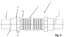
- the outer part 6 has a hexagonal contour at the reference numeral 6c on the outside, which can be acted on with appropriate tools, which facilitates handling. This hexagonal contour at reference number 6c is also in figure 3 good to see.
- a clear inner diameter of the outer part 6 in the area of the projection 6a corresponds to the same outer diameter of the inner part 5 and the connecting part 7, in particular in the area of the radial projections 5b and 7a mentioned, which is not shown in the figures for reasons of clarity is not further indicated.
- connection part 7 and the inner part 5 bear against one another without a material connection, as mentioned.
- an axial extension of the projection 6a of the outer part 6 is smaller than an axial extension of the radial projection 7a of the connecting part, so that in this area there is an outer step in which the already mentioned weld seam at reference number 8 can be arranged can.
- the inner hose 2 acts as a plastic lining for the outer hose 3, with a significant portion of the length of the inner hose 2 being enclosed by the outer hose 3.
- the outer tube 3 acts as a support element for the inner tube 2 due to its inherently higher compressive strength.
- both the outer hose 3 and the inner hose 2 are vacuum-tight, preferably up to a maximum permissible leakage of 1.00 E-9 mbar*l/s.
- the leak path which has already been mentioned repeatedly, is formed between the inner part 5 and the connection part 7 along the parting line shown there up to the area of the outer, "last" weld seam at reference number 8. This is accordingly not through the inner tube 2, which is between the inner part 5 and the outer part 6 is clamped (pressed), masked and can therefore be checked for leaks in the manner already mentioned. Since, in addition, the weld connection mentioned at reference number 8 is located at a greater distance from the inner tube 2, this is effectively protected against thermal damage, which has a favorable effect on the safety and quality of the entire tube assembly 1.
- the invention is in no way limited to the bilaterally symmetrical configuration shown in the figures, but of course also includes hose assemblies in which the described connection arrangement 4 is only present on one side.
- the connecting part 7 is used with its free end for connection to further customer-specific pipeline or hose line elements and can be configured flexibly in this area according to the respective requirements, which does not need to be discussed further here.
- the outer hose 3 is first connected (welded) to the outer part 6 or the outer parts 6 at reference number 3a with a material fit and lined with the inner hose 2, or vice versa. Then the inner part 5 or the inner parts 5 are inserted with the inlet slope 5a first into the outer part 6 or the outer parts 6 and the inner tube 2, so that the inner tube 2, as shown, is clamped between the inner part 5 and the outer part 6 until the Inner part 5 with its thickening 5b at the shoulder 6b (cf. figure 2 ) of the outer part 6 is present.
- connection part 7 or the connecting parts 7 are attached at the ends, as shown, and then connected to the respective outer part 6 in a materially bonded manner at reference number 8 by means of a circumferential (laser) weld seam.
- a helium leak test can then be performed to verify that the connection at reference number 8 is made sufficiently tight. In particular, such a leak test was not possible with the prior art.
Landscapes
- Engineering & Computer Science (AREA)
- General Engineering & Computer Science (AREA)
- Mechanical Engineering (AREA)
- Rigid Pipes And Flexible Pipes (AREA)
Abstract
einen Innenschlauch 2; einen Außenschlauch 3, der den Innenschlauch 2 abschnittweise umgibt, sodass wenigstens ein freies Ende 2a des Innenschlauchs 2 aus dem Außenschlauch 3 herausragt; sowie
eine Verbindungsanordnung 4 mit:
wenigstens einem hülsenförmigen Innenteil 5, welches Innenteil 5 in das freie Ende 2a des Innenschlauchs 2 eingeführt ist; und
wenigstens einem hülsenförmigen Außenteil 6, welches das Innenteil 5 umgibt und mit dem Außenschlauch 3 fluiddicht verbunden ist, vorzugsweise stoffschlüssig, höchst vorzugsweise verschweißt;
bei der das freie Ende 2a des Innenschlauchs 2 zwischen dem Innenteil 5 und dem Außenteil 6 geklemmt ist und bei der das Außenteil 6 mit einem umlaufenden Vorsprung 6a endständig gegenüber dem Innenteil 5 hervorsteht.
Description
- Die Erfindung betrifft eine Schlauchbaugruppe, umfassend: einen Innenschlauch, einen Außenschlauch, der den Innenschlauch abschnittsweise umgibt, sodass wenigstens ein freies Ende des Innenschlauchs aus dem Außenschlauch herausragt; und eine Verbindungsordnung mit: wenigstens einem hülsenförmigen Innenteil, welches Innenteil in das freie Ende des Innenschlauchs eingeführt ist; und wenigstens einem hülsenförmigen Außenteil, welches Außenteil das Innenteil umgibt und mit dem Außenschlauch fluiddicht verbunden ist, vorzugsweise stoffschlüssig, höchst vorzugsweise verschweißt, gemäß Anspruch 1.
- Eine ähnliche Schlauchbaugruppe ist aus der
EP 2 327 914 B1 bekannt. Die vorbekannte Schlauchbaugruppe umfasst neben einem Innenschlauch und einem Außenschlauch noch eine Kopplungsanordnung mit einer ersten Klemmbefestigung und einer zweiten Klemmbefestigung. Die erste Klemmbefestigung ist mit der zweiten Klemmbefestigung verbunden, und ein erster Endabschnitt des Innenschlauchs ist zwischen der ersten Klemmbefestigung und der zweiten Klemmbefestigung befestigt, d.h. eingeklemmt. Des Weiteren ist bei dem vorbekannten Gegenstand die erste Klemmbefestigung mit der zweiten Klemmbefestigung durch Schweißen verbunden. - Bei einer solchen Ausgestaltung ist insbesondere als nachteilig anzusehen, dass die genannte Schweißverbindung nicht ohne Weiteres überprüfbar ist, beispielsweise auf Leckagen, da sie durch den regelmäßig aus Kunststoff bestehenden Innenschlauch (sog. Kunststoffliner) maskiert ist. Außerdem kommt es beim Verschweißen zu einer relativ großen thermischen Belastung des Innenschlauchs (des Kunststoffliners), sodass zwecks einer zerstörungsfreien Herstellung relativ große Baulängen erforderlich sind, was sich nachteilig auf den Bauraumbedarf auswirkt.
- Der Erfindung liegt die Aufgabe zugrunde, eine alternative Schlauchbaugruppe der weiter oben genannten Art anzugeben, bei der insbesondere eine umfassende Prüfbarkeit auf Dichtheit, beispielsweise mittels Helium-Lecktest, möglich ist. Außerdem soll die thermische Belastung reduziert und eine verkürzte Bauweise ermöglicht werden.
- Die Erfindung löst diese Aufgaben durch eine Schlauchbaugruppe mit den Merkmalen des Anspruchs 1. Vorteilhafte Weiterbildungen der erfindungsgemäßen Schlauchbaugruppe sind Gegenstand von Unteransprüchen.
- Eine erfindungsgemäße Schlauchbaugruppe umfasst: einen Innenschlauch; einen Außenschlauch, der den Innenschlauch abschnittweise umgibt, sodass wenigstens ein freies Ende des Innenschlauchs aus dem Außenschlauch herausragt; und eine Verbindungsanordnung mit: wenigstens einem hülsenförmigen Innenteil, welches Innenteil in das freie Ende des Innenschlauchs eingeführt ist; und wenigstens einem hülsenförmigen Außenteil, welches das Innenteil umgibt und mit dem Außenschlauch fluiddicht verbunden ist, vorzugsweise stoffschlüssig, höchst vorzugsweise verschweißt. Dabei ist erfindungsgemäß das freie Ende des Innenschlauchs zwischen dem Innenteil und dem Außenteil geklemmt, und das Außenteil steht mit einem umlaufenden Vorsprung endständig gegenüber dem Innenteil hervor.
- Aufgrund der Tatsache, dass das Außenteil mit seinem umlaufenden Vorsprung endständig gegenüber dem Innenteil hervorsteht, lässt sich im Bereich dieses Vorsprungs ein zusätzliches, kundenseitiges oder kundenspezifisches Anschlussteil ansetzen und mit dem Außenteil im Bereich des Vorsprungs (von außen) stoffschlüssig verbinden, wodurch keine stoffschlüssige Verbindung mehr zwischen dem Innenteil und dem Außenteil erforderlich ist, welche Teile ansonsten den aus der Stand der Technik bekannten ersten und zweiten Klemmbefestigungen entsprechen. Auf diese Weise kommt es zu keiner unmittelbaren thermischen Belastung des Innenschlauchs, wodurch kürzere Bauformen ermöglicht werden. Außerdem ist die vorstehend genannte Schweißverbindung zwischen dem Außenteil und dem kundenseitigen Anschlussteil grundsätzlich auf Dichtheit prüfbar, da sie nicht durch den Innenschlauch maskiert ist. Auf diese Weise überwindet die vorliegende Erfindung die aus dem Stand der Technik bekannten Nachteile.
- "Kundenseitig" bedeutet in diesem Kontext, dass das genannte Anschlussteil an einem (freien) Ende so ausgestaltet ist oder sein kann, dass es mit weiteren, anwendungs- oder kundenspezifischen Leitungskomponenten kompatibel ist. Hier sind also vielfältige Ausgestaltungen möglich, worauf es vorliegend nicht weiter ankommt.
- Eine erste, äußerst bevorzugte Weiterbildung der erfindungsgemäßen Schlauchbaugruppe sieht vor, dass das Innenteil und das Außenteil ohne stoffschlüssige Verbindung gefügt sind. Hierdurch ergibt sich unmittelbar eine geringere thermische Belastung des Innenschlauchs, was insbesondere dann von großem Vorteil ist, wenn dieser aus einem Kunststoffmaterial hergestellt ist.
- Eine andere Weiterbildung der erfindungsgemäßen Schlauchbaugruppe sieht vor, dass diese ein zusätzliches Anschlussteil aufweist, wie bereits erwähnt, das sich in einem verbundenen Zustand axial an das Innenteil anschließt oder axial an das Innenteil anschließbar ist, wobei das Außenteil in dem verbundenen Zustand mit seinem umlaufenden Vorsprung das Anschlussteil in einem Abschnitt umgibt.
- Das genannte Anschlussteil kann als kundenseitiges Anschlussteil zum Verbinden der restlichen Schlauchbaugruppe mit weiteren Bestandteilen einer Leitungsanordnung dienen, wie bereits erwähnt. Aufgrund des umlaufenden Vorsprungs besteht die Möglichkeit, das Anschlussteil mit dem Außenteil (insbesondere stoffschlüssig, beispielsweise mittels einer Laserschweißnaht) zu verbinden, ohne dass eine zusätzliche stoffschlüssige Verbindung zwischen Anschlussteil und Innenteil erforderlich wäre. Auf diese Weise ergibt sich zwischen dem Innenteil (auch als "Presshülse" bezeichnet) und dem Anschlussteil (Einschubteil) ein Leckpfad für die Prüfung der genannten Schweißverbindung (Laserschweißnaht), um insbesondere deren Dichtheit zu überprüfen. Dies ist beispielsweise für eine bevorzugte Verwendung der erfindungsgemäßen Schlauchbaugruppe als Teil einer Wasserleitung für Halbleitermaschinen vorteilhaft, bei welchen die Schlauchbaugruppe dazu dient, hochgradig sauberes Wasser zu leiten, während außerhalb ein Ultrahochvakuum ausgebildet ist.
- Eine andere Weiterbildung der erfindungsgemäßen Schlauchbaugruppe sieht in diesem Zusammenhang dementsprechend vor, dass das Anschlussteil und das Außenteil im Bereich des Vorsprungs fluiddicht verbunden oder verbindbar sind, vorzugsweise stoffschlüssig, höchst vorzugsweise verschweißt, insbesondere mittels der vorstehend bereits erwähnten Laserschweißnaht, welche Schweißnaht vorzugsweise vollumfänglich zwischen dem Außenteil im Bereich des genannten Vorsprungs und dem Anschlussteil ausgebildet ist.
- Eine wieder andere Weiterbildung der erfindungsgemäßen Schlauchbaugruppe sieht vor, dass das Anschlussteil und das Innenteil einen gleichen, vorzugsweise konstanten, lichten Innendurchmesser aufweisen. Auf diese Weise ergibt sich eine glatte, verwirbelungsfreie Anbindung, was in vielen Anwendungsbereichen von Vorteil sein kann.
- Noch eine andere Weiterbildung der erfindungsgemäßen Schlauchbaugruppe sieht vor, dass das Anschlussteil und das Innenteil an ihren einander zugewandten oder zuzuwendenden Enden jeweils einen radialen, umlaufenden Vorsprung bzw. eine entsprechende Verdickung aufweisen, vorzugsweise mit gleichen radialen Abmessungen. Auf diese Weise können das Anschlussteil und das Innenteil im Bereich der genannten Vorsprünge flächig miteinander in Anlage gebracht werden, was die Verbindungsqualität verbessern und die Stabilität der Schlauchbaugruppe erhöhen kann.
- Noch eine andere Weiterbildung der erfindungsgemäßen Schlauchbaugruppe sieht vor, dass ein lichter Innendurchmesser des Außenteils im Bereich des Vorsprungs einem gleichen Außendurchmesser des Innenteils und des Anschlussteils entspricht, insbesondere im Bereich der vorstehend erwähnten Vorsprünge. Auf diese Weise ergibt sich in dem genannten Bereich eine Verbindungsmöglichkeit für die genannten Komponenten ohne Kavitäten, eingeschlossene Volumina oder Toträume, wodurch sich die Qualität und Stabilität der Verbindung verbessern lässt, insbesondere im Hinblick auf die genannten Vakuumanwendungen.
- Es hat sich als äußerst vorteilhaft erwiesen, wenn im Rahmen einer anderen Weiterbildung der erfindungsgemäßen Schlauchbaugruppe das Anschlussteil und das Innenteil in dem verbundenen Zustand ohne stoffschlüssige Verbindung aneinander anliegen. Auf einen besonderen Vorteil einer solchen Ausgestaltung wurde bereits hingewiesen, weil auf diese Weise ein Leckpfad für die Prüfung der stoffschlüssigen Verbindung (Laserschweißnaht) zwischen Anschlussteil und Außenteil ausbildbar ist, sodass die Verbindungsqualität kontrollierbar ist.
- Eine andere Weiterbildung der erfindungsgemäßen Schlauchbaugruppe sieht noch vor, dass eine axiale Erstreckung des Vorsprungs kleiner ist als eine axiale Erstreckung des radialen Vorsprungs bzw. der genannten Verdickung des Anschlussteils. Bei dem genannten Vorsprung handelt es sich um den eingangs erwähnten axialen Vorsprung des Außenteils gegenüber dem Innenteil. Auf diese Weise kann die bereits mehrfach erwähnte stoffschlüssige Verbindung (Laserschweißnaht) zwischen Außenteil und Anschlussteil in einem Bereich ausgebildet werden, in dem das Anschlussteil den genannten radialen Vorsprung aufweist, was aus Gründen der Verbindungsstabilität sowie auch der thermischen Belastung für weitere Bauteile von Vorteil ist.
- Eine vorteilhafte andere Weiterbildung der erfindungsgemäßen Schlauchbaugruppe sieht noch vor, dass das Innenteil auf seiner in das freie Ende des Innenschlauchs eingeführten Seite eine Einführschräge aufweist. Auf diese Weise wird das Fügen der einzelnen Komponenten der Schlauchbaugruppe erleichtert, insbesondere das Klemmen von Innenschlauch zwischen Innenteil und Außenteil. Außerdem kann auf diese Weise für eine glatte, verwirbelungsfreie Anbindung des Innenschlauchs gesorgt werden.
- Wieder eine andere Weiterbildung der erfindungsgemäßen Schlauchbaugruppe sieht vor, dass das Außenteil eine radial nach innen vorspringende, umlaufende Schulter aufweist, an der das Innenteil anliegt, vorzugsweise mit dem betreffenden radialen Vorsprung bzw. der genannten Verdickung. Auf diese Weise ergibt sich eine sichere, definierte Verbindung von Innenteil und Außenteil.
- Weiterhin kann bei einer anderen Ausgestaltung der erfindungsgemäßen Schlauchbaugruppe vorgesehen sein, dass das Außenteil an seiner Außenumfangsfläche abschnittweise eine Sechskantkontur aufweist. Eine solche Sechskantkontur kann die Handhabung bzw. Montage der erfindungsgemäßen Schlauchbaugruppe erleichtern.
- Noch eine andere Weiterbildung der erfindungsgemäßen Schlauchbaugruppe sieht vor, dass an beiden Enden des Innenschlauchs und des Außenschlauchs jeweils ein hülsenförmiges Innenteil und ein hülsenförmiges Außenteil angeordnet sind, die jeweils ausgebildet sind, wie weiter oben ausführlich beschrieben, und die klemmend mit dem Innenschlauch zusammenwirken. Mit anderen Worten: Es kann vorteilhaft sein, wenn die Schlauchbaugruppe an beiden Enden gleich bzw. symmetrisch ausgebildet ist und entsprechend auch an beiden Enden mit einem Anschlussteil versehen werden kann, wie weiter oben ausführlich beschrieben.
- Nach Erkenntnissen der Anmelderin hat es sich außerdem als vorteilhaft erwiesen, wenn bei einer erfindungsgemäßen Schlauchbaugruppe, d.h. einer entsprechenden Weiterbildung derselben der Innenschlauch in einem Kunststoff ausgebildet ist, vorzugsweise in einem Kunststoffmaterial, das vakuumverträglich ist, zum Beispiel PTFE (Polytetrafluorethylen) und/oder PFA (Perfluoralkoxylalkan). Eine solche Ausgestaltung hat sich insbesondere für die bevorzugte Verwendung als Wasserleitung für Halbleitermaschinen als günstig erwiesen.
- Bei entsprechender Weiterbildung der erfindungsgemäßen Schlauchbaugruppe kann außerdem vorgesehen sein, dass der Innenschlauch als Kunststoffauskleidung des Außenschlauchs ausgebildet ist, wobei der größte Teil der Länge des Innenschlauchs von dem Außenschlauch umschlossen ist. Solche Ausgestaltungen haben sich in der praktischen Verwendung als besonders vorteilhaft und günstig erwiesen.
- Bei noch einer anderen Weiterbildung der erfindungsgemäßen Schlauchbaugruppe kann vorgesehen sein, dass der Außenschlauch eine Wandung aus einem starren Material, insbesondere einem metallischen Material, aufweist, wobei der Außenschlauch vorzugsweise als flexibler Metallschlauch ausgebildet ist. Auch eine solche Ausgestaltung hat sich nach den Erkenntnissen der Anmelderin als in der Praxis äußerst vorteilhaft erwiesen, insbesondere für die bereits erwähnten Vakuumanwendungen.
- Als besonders vorteilhaft hat es sich auch erwiesen, wenn bei entsprechender Weiterbildung der erfindungsgemäßen Schlauchbaugruppe der Außenschlauch als Wellschlauch, insbesondere Ringwellschlauch, als Wickelschlauch oder aus mehreren Segmenten zusammengesetzt ausgebildet ist. Auf diese Weise lässt sich der weiter oben bereits erwähnte flexible Metallschlauch einfach und prozesssicher herstellen.
- Als äußerst vorteilhaft hat es sich herausgestellt, wenn der Außenschlauch bei einer entsprechenden Weiterbildung der erfindungsgemäßen Schlauchbaugruppe ein Edelstahlschlauch ist. Dieser kann aufgrund seiner größeren Druckfestigkeit den Innenschlauch stützen.
- Des Weiteren hat es sich als vorteilhaft herausgestellt, wenn bei einer entsprechenden Weiterbildung der erfindungsgemäßen Schlauchbaugruppe sowohl der Außenschlauch als auch der Innenschlauch vakuumdicht ausgebildet sind, vorzugsweise bis hin zu einer maximal zulässigen Leckage von insbesondere 1,00 E-9 mbar*l/s (Millibar mal Liter pro Sekunde).
- Es wurde bereits mehrfach darauf hingewiesen, dass es besonders vorteilhaft ist, wenn bei einer entsprechenden Weiterbildung der erfindungsgemäßen Schlauchbaugruppe ein Leckpfad zwischen dem Innenteil und dem Anschlussteil vorhanden ist, weil hierdurch die Möglichkeit geschaffen wird, die vorteilhafterweise vorhandene stoffschlüssige Verbindung (Laserschweißnaht) zwischen dem Außenteil und dem Anschlussteil im Bereich des axialen Vorsprungs des Außenteils gegenüber dem Innenteil zu überprüfen, beispielsweise mittels eines Helium-Lecktests.
- Im Rahmen der vorliegenden Erfindung bzw. der vorstehend beschriebenen vorteilhaften Weiterbildungen ist somit - anders als beim Stand der Technik - die "letzte" Schweißnaht der Schlauchbaugruppe prüfbar, da sie nicht durch den Innenschlauch (Kunststoffliner) maskiert ist.
- Es besteht insbesondere die Möglichkeit, eine glatte, verwirbelungsfreie Anbindung des Liners (Innenschlauch) an einen Schlauchanschluss (Anschlussteil) zu schaffen. Dies kann einhergehen mit einer stoffschlüssigen, vakuumdichten Verbindung aller außenliegenden Komponenten zusammen mit einer vollständigen Prüfbarkeit auf Dichtheit, insbesondere bis hin zu Werten von 1,00 E-9 mbar*l/s, beispielsweise mittels Helium-Lecktest. Dabei bestehen vorteilhafterweise keinerlei Kavitäten, eingeschlossene Volumina oder Toträume, die sich insbesondere bei den genannten Vakuum-Anwendungen als nachteilig erweisen könnten.
- Der bereits mehrfach erwähnte innenliegende Spalt zwischen Einschubteil (Anschlussteil) und Presshülse (Innenteil) stellt vorteilhafterweise einen Leckpfad für die Prüfung der genannten stoffschlüssigen Verbindung (Laserschweißnaht) dar.
- Konstruktionsgemäß ergibt sich außerdem nur eine geringe thermische Belastung des Innenschlauchs (Liners) beim Schweißen, was insbesondere bei Innenschläuchen aus Kunststoff von Vorteil ist.
- Die erfindungsgemäße Konstruktion geht einher mit einer guten Reinigbarkeit aller Einzelteile, verbunden mit einer partikel- und schmierstofffreien Montage.
- Ein besonderes Merkmal der vorliegenden Erfindung - bei entsprechender Ausgestaltung - ist die Trennung zwischen dem innenliegenden Klemmelement für den Innenschlauch, das heißt dem Innenteil und dem kundenseitigen Anschluss (Anschlussteil bzw. Einschubteil), wobei vorteilhafterweise keine stoffschlüssige Verbindung zwischen den beiden Elementen (Innenteil und Außenteil) besteht, welche den Liner (Innenschlauch) verpressen.
- Auf die erreichbaren bzw. erreichten technischen Vorteile wurde wiederholt hingewiesen: Dies sind in erster Linie der mögliche Leckpfad zwischen dem inneren Klemmpartner (Innenteil) und dem Kundenanschluss (Anschlussteil), wodurch die letzte Schweißnaht prüfbar wird, insbesondere mittels eines Helium-Lecktests. Außerdem besteht die Möglichkeit einer thermischen Trennung zwischen dem inneren Klemmpartner (Innenteil) und dem Anschlussteil, was zu einer geringeren thermischen Belastung des Innenschlauchs führt, was insbesondere bei einer Ausgestaltung des Innenschlauchs aus Kunststoff (Kunststoffliner) von Vorteil ist. Dadurch ergibt sich in vorteilhafter Weise eine mögliche kürzere Bauweise der Gesamtanordnung.
- Weitere Eigenschaften und Vorteile der Erfindung ergeben sich aus der nachfolgenden Beschreibung von Ausführungsbeispielen anhand der Zeichnung.
- Figur 1
- zeigt eine Ausgestaltung der erfindungsgemäßen Schlauchbaugruppe, teilweise im Längsschnitt;
- Figur 2
- zeigt die Ausgestaltung gemäß
Figur 1 vollständig im Längsschnitt; und - Figur 3
- zeigt eine Außenansicht der Ausgestaltung gemäß den
Figuren 1 und 2 . -
Figur 1 zeigt, teilweise im Längsschnitt (Längsachse L), eine Ausgestaltung der erfindungsgemäßen Schlauchbaugruppe, die insgesamt mit dem Bezugszeichen 1 bezeichnet ist. Die Schlauchbaugruppe 1 ist an ihren beiden Enden identisch ausgebildet, sodass vorliegend zwecks Vereinfachung nur eine Seite der Schlauchbaugruppe 1 explizit beschrieben wird. Diese Beschreibung gilt auch für die andere Seite der Schlauchbaugruppe 1 entsprechend. - Des Weiteren entsprechen in allen Figuren gleiche Bezugszeichen gleichen oder zumindest gleichwirkenden Elementen, sodass vorliegend nicht auf alle Figuren gesondert einzugehen ist.
- Die Schlauchbaugruppe 1 umfasst einen Innenschlauch 2, der vorliegend als Kunststoffliner aus PTFE oder PFA ausgebildet ist, wobei die Erfindung allerdings keinesfalls auf die genannten Materialien beschränkt ist. Der Innenschlauch 2 ist über einen großen Teil seiner Länge innerhalb eines Außenschlauchs 3 angeordnet, der entsprechend den Innenschlauch 2 abschnittsweise umgibt. Dabei ragt ein freies Ende 2a des Innenschlauchs 2 aus dem Außenschlauch 3 heraus. Der Außenschlauch 2 ist vorliegend als Ringwellschlauch aus einem metallischen Material ausgebildet, vorzugsweise aus Edelstahl. Auch hier ist die Erfindung keinesfalls auf die genannte Materialwahl beschränkt.
- Außerdem umfasst die Schlauchbaugruppe eine Verbindungsanordnung 4, die wenigstens ein hülsenförmiges Innenteil 5 (Presshülse) und ein hülsenförmiges Außenteil 6 (der sog. "Schlauchadapter") umfasst. Das Innenteil 5 ist an das freie Ende 2a des Innenschlauchs 2 eingeführt und weist in diesem Bereich eine Einlaufschräge 5a auf. An seinem anderen Ende besitzt das Innenteil 5 eine radiale Verdickung bzw. einen radialen Vorsprung 5b. Das Außenteil 6 umgibt das Innenteil 5 und ist mit dem Außenschlauch 3 bei Bezugszeichen 3a fluiddicht verbunden, vorzugsweise stoffschlüssig, höchst vorzugsweise verschweißt. Das genannte freie Ende 2a des Innenschlauchs 2 ist zwischen dem Innenteil 5 und dem Außenteil 6 geklemmt (verpresst). Das Außenteil 6 weist einen umlaufenden Vorsprung 6a an seinem freien Ende, das heißt an seinem von dem Außenschlauch 3 abgewandten Ende, auf, welcher Vorsprung 6a axial gegenüber dem Innenteil 5 hervorsteht. Bei Bezugszeichen 6b (vgl.
Figur 2 ) weist das Außenteil 6 eine innenliegende, umlaufende Schulter auf, an der das Innenteil 5 mit der genannten radialen Verdickung 5b anliegt. - In axialer Richtung an das Innenteil 5 angrenzend ist ein (kunden- oder anwendungsspezifisches) Anschlussteil 7 (Einschubteil) angeordnet, welches an seinem dem Innenteil 5 zugewandten Ende ebenfalls eine radiale Verdickung (radialer Vorsprung) 7a aufweist, dessen Abmessungen in radialer Richtung dem Vorsprung 5b des Innenteils 5 entsprechen, sodass sich in diesem Bereich eine großflächige Anlage von Innenteil 5 und Anschlussteil 7 ergibt. Dabei entspricht ein lichter Innendurchmesser des Innenteils einem lichten Innendurchmesser d des Anschlussteils 7, sodass sich in diesem Bereich eine durchgängige, glattwandige Rohrleitung ergibt. Das Außenteil 6 und das Anschlussteil 7 sind bei Bezugszeichen 8 mittels einer (nicht dargestellten) umlaufenden (Laser-)Schweißnaht stoffschlüssig verbunden, während zwischen dem Innenteil 5 und dem Außenteil 6 einerseits sowie zwischen dem Innenteil 5 und dem Anschlussteil 7 andererseits keinerlei stoffschlüssige Verbindungen vorgesehen sind. Der Innenschlauch 2 ist mit seinem freien Ende 2a zwischen dem Innenteil 5 und dem Außenteil 6 klemmend gehalten, worauf bereits hingewiesen wurde. Weil insbesondere zwischen dem Innenteil 5 und dem Anschlussteil 7 keinerlei stoffschlüssige Verbindung ausgebildet ist, ergibt sich auf diese Weise ein Leckpfad von innen bis in den Bereich der Schweißverbindung bei Bezugszeichen 8, sodass diese in einfacher Weise auf ihre Dichtheit überprüfbar ist.
- Wie sich insbesondere aus
Figur 1 ergibt, weist das Außenteil 6 bei Bezugszeichen 6c außen eine Sechskantkontur auf, auf die mit entsprechenden Werkzeugen eingewirkt werden kann, was die Handhabung erleichtert. Diese Sechskantkontur bei Bezugszeichen 6c ist auch inFigur 3 gut erkennbar. - Wie man den Figuren noch entnimmt, entspricht ein lichter Innendurchmesser des Außenteils 6 im Bereich des Vorsprungs 6a einem gleichen Außendurchmesser des Innenteils 5 und des Anschlussteils 7, insbesondere im Bereich der genannten radialen Vorsprünge 5b bzw. 7a, was in den Figuren aus Gründen der Übersichtlichkeit nicht weiter bezeichnet ist.
- Dargestellt ist in den Figuren der im einleitenden Teil der Beschreibung erwähnte verbundene Zustand, in dem das Anschlussteil 7 und das Innenteil 5 ohne stoffschlüssige Verbindung aneinander anliegen, wie erwähnt.
- Wie man den Figuren noch entnimmt, ist eine axiale Erstreckung des Vorsprungs 6a des Außenteils 6 kleiner als eine axiale Erstreckung des radialen Vorsprungs 7a des Anschlussteils, sodass sich in diesem Bereich eine äußere Stufe ergibt, in der die bereits erwähnte Schweißnaht bei Bezugszeichen 8 angeordnet sein kann.
- Bei der gezeigten Schlauchbaugruppe 1 fungiert der Innenschlauch 2 als Kunststoffauskleidung des Außenschlauchs 3, wobei ein beträchtlicher Teil der Länge des Innenschlauchs 2 von dem Außenschlauch 3 umschlossen ist. Umgekehrt fungiert der Außenschlauch 3 aufgrund seiner inhärent höheren Druckfestigkeit als Stützelement für den Innenschlauch 2.
- Vorteilhafterweise sind bei der dargestellten Ausführungsform sowohl der Außenschlauch 3 als auch der Innenschlauch 2 vakuumdicht ausgeführt, vorzugsweise bis zu einer maximal zulässigen Leckage von 1,00 E-9 mbar*l/s.
- Der bereits wiederholt angesprochene Leckpfad ist gebildet zwischen dem Innenteil 5 und dem Anschlussteil 7 entlang der dort gezeigten Trennlinie bis in den Bereich der äußeren, "letzten" Schweißnaht bei Bezugszeichen 8. Diese ist entsprechend nicht durch den Innenschlauch 2, der zwischen Innenteil 5 und Außenteil 6 geklemmt (verpresst) ist, maskiert und kann deshalb in der bereits angesprochenen Art und Weise auf Dichtheit überprüft werden. Da sich zudem die genannte Schweißverbindung bei Bezugszeichen 8 in größerer Entfernung von dem Innenschlauch 2 befindet, ist dieser wirksam vor thermischer Beschädigung geschützt, was die Sicherheit und Qualität der gesamten Schlauchbaugruppe 1 günstig beeinflusst.
- Die Erfindung ist keinesfalls auf die in den Figuren gezeigte beidseitig-symmetrische Ausgestaltung beschränkt, sondern umfasst selbstverständlich auch Schlauchbaugruppen, bei denen die beschriebene Verbindungsanordnung 4 nur auf einer Seite vorhanden ist.
- Das Anschlussteil 7 dient mit seinem freien Ende zur Anbindung an kundenspezifische weitere Rohrleitungs- bzw. Schlauchleitungselemente und kann in diesem Bereich den jeweiligen Anforderungen entsprechend flexibel ausgestaltet sein, worauf vorliegend nicht weiter einzugehen ist.
- Zur Herstellung der erfindungsgemäßen Schlauchbaugruppe wird zunächst der Außenschlauch 3 bei Bezugszeichen 3a stoffschlüssig mit dem Außenteil 6 bzw. den Außenteilen 6 verbunden (verschweißt) und mit dem Innenschlauch 2 ausgekleidet, oder umgekehrt. Anschließend wird das Innenteil 5 bzw. werden die Innenteile 5 mit der Einlaufschräge 5a voran in das Außenteil 6 bzw. die Außenteile 6 und den Innenschlauch 2 eingeführt, sodass der Innenschlauch 2, wie dargestellt, zwischen Innenteil 5 und Außenteil 6 eingeklemmt wird, bis das Innenteil 5 mit seiner Verdickung 5b an der Schulter 6b (vgl.
Figur 2 ) des Außenteils 6 anliegt. Anschließend wird das Anschlussteil 7 bzw. werden die Anschlussteile 7 endständig angesetzt, wie gezeigt, und danach bei Bezugszeichen 8 mittels einer umlaufenden (Laser-)Schweißnaht mit dem jeweiligen Außenteil 6 stoffschlüssig verbunden. Anschließend kann ein Helium-Lecktest durchgeführt werden, um zu überprüfen, ob die Verbindung bei Bezugszeichen 8 hinreichend dicht ausgeführt ist. Insbesondere eine solche Dichtheitsprüfung war nach dem Stand der Technik nicht möglich.
Claims (15)
- Schlauchbaugruppe (1), umfassend:einen Innenschlauch (2);einen Außenschlauch (3), der den Innenschlauch (2) abschnittweise umgibt,sodass wenigstens ein freies Ende (2a) des Innenschlauchs (2) aus dem Außenschlauch (3) herausragt; undeine Verbindungsanordnung (4) mit:wenigstens einem hülsenförmigen Innenteil (5), welches Innenteil (5) in das freie Ende (2a) des Innenschlauchs (2) eingeführt ist; undwenigstens einem hülsenförmigen Außenteil (6), welches das Innenteil (5) umgibt und mit dem Außenschlauch (3) fluiddicht verbunden ist, vorzugsweise stoffschlüssig, höchst vorzugsweise verschweißt;bei der das freie Ende (2a) des Innenschlauchs (2) zwischen dem Innenteil (5) und dem Außenteil (6) geklemmt ist und bei der das Außenteil (6) mit einem umlaufenden Vorsprung (6a) endständig gegenüber dem Innenteil (5) hervorsteht.
- Schlauchbaugruppe (1) nach Anspruch 1, bei der
das Innenteil (5) und das Außenteil (5) ohne stoffschlüssige Verbindung gefügt sind. - Schlauchbaugruppe (1) nach Anspruch 1 oder 2, mit
einem zusätzlichen Anschlussteil (7), das sich in einem verbundenen Zustand axial an das Innenteil (5) anschließt oder axial an das Innenteil (5) anschließbar ist, bei der das Außenteil (6) in dem verbundenen Zustand mit seinem umlaufenden Vorsprung (6a) das Anschlussteil (7) in einem Abschnitt umgibt, wobei das Anschlussteil (7) und das Außenteil (6) im Bereich des Vorsprungs (6a) insbesondere fluiddicht verbunden oder verbindbar sind, vorzugsweise stoffschlüssig, höchst vorzugsweise verschweißt. - Schlauchbaugruppe (1) nach Anspruch 3, bei der
das Anschlussteil (7) und das Innenteil (5) einen gleichen, vorzugsweise konstanten, lichten Innendurchmesser (d) aufweisen, und/oder bei der das Anschlussteil (7) und das Innenteil (5) an ihren einander zugewandten oder zuzuwendenden Enden jeweils einen radialen, umlaufenden Vorsprung (5b, 7a) aufweisen, vorzugsweise mit gleichen radialen Abmessungen. - Schlauchbaugruppe (1) nach einem der Ansprüche 3 oder 4, bei der ein lichter Innendurchmesser des Außenteils (6) im Bereich des Vorsprungs (6a) einem gleichen Außendurchmesser des Innenteils (5) und des Anschlussteils (7) entspricht, insbesondere im Bereich der radialen Vorsprünge (5b, 7a) gemäß Anspruch 4.
- Schlauchbaugruppe (1) nach einem der Ansprüche 3 bis 5, bei der das Anschlussteil (7) und das Innenteil (5) in dem verbundenen Zustand ohne stoffschlüssige Verbindung aneinander anliegen.
- Schlauchbaugruppe (1) nach einem der Ansprüche 3 bis 6, bei der eine axiale Erstreckung des Vorsprungs (6a) kleiner ist als eine axiale Erstreckung des radialen Vorsprungs (7a) des Anschlussteils (7).
- Schlauchbaugruppe (1) nach einem der Ansprüche 1 bis 7, bei der das Innenteil (5) auf seiner in das freie Ende (2a) des Innenschlauchs (2) eingeführten Seite eine Einführschräge (5a) aufweist.
- Schlauchbaugruppe (1) nach einem der Ansprüche 1 bis 8, bei der das Außenteil (6) eine radial nach innen vorspringende, umlaufende Schulter (6b) aufweist, an der das Innenteil (5) anliegt, vorzugsweise mit dem betreffenden Vorsprung (5b) gemäß Anspruch 4.
- Schlauchbaugruppe (1) nach einem der Ansprüche 1 bis 9, bei der das Außenteil (6) an seiner Außenumfangsfläche abschnittweise eine Sechskantkontur (6c) aufweist.
- Schlauchbaugruppe (1) nach einem der Ansprüche 1 bis 10, bei der an beiden Enden des Innenschlauchs (2) und des Außenschlauchs (3) jeweils ein hülsenförmiges Innenteil (5) und ein hülsenförmiges Außenteil (6) angeordnet sind, die gemäß Anspruch 1 ausgebildet sind und klemmend mit dem Innenschlauch (2) zusammenwirken.
- Schlauchbaugruppe (1) nach einem der Ansprüche 1 bis 11, bei der der Innenschlauch (2) in einem Kunststoff ausgebildet ist, vorzugsweise in einem Kunststoffmaterial, das vakuumverträglich ist, z.B. PTFE (Polytetrafluorethylen) und/oder PFA (Perfluoralkoxylalkan), und/oder bei der der Innenschlauch (2) als Kunststoffauskleidung des Außenschlauchs (3) ausgebildet ist, wobei vorzugsweise ein größter Teil der Länge des Innenschlauchs (2) von dem Außenschlauch (3) umschlossen ist.
- Schlauchbaugruppe (1) nach einem der Ansprüche 1 bis 12, bei der der Außenschlauch (3) eine Wandung aus einem starren Material, insbesondere einem metallischen Material, aufweist, wobei der Außenschlauch (3) vorzugsweise als flexibler Metallschlauch ausgebildet ist, und/oder bei der der Außenschlauch (3) als Wellschlauch, insbesondere Ringwellschlauch, als Wickelschlauch oder aus mehreren Segmenten zusammengesetzt ausgebildet ist, und/oder bei der der Außenschlauch (3) ein Edelstahlschlauch ist, der vorzugsweise aufgrund seiner höheren Druckbeständigkeit den Innenschlauch (2) stützt.
- Schlauchbaugruppe (1) nach einem der Ansprüche 1 bis 13, bei der sowohl der Außenschlauch (3) als auch der Innenschlauch (2) vakuumdicht, vorzugsweise bis 1,00E-9 mbar*l/s, ausgebildet sind.
- Schlauchbaugruppe (1) nach einem der Ansprüche 1 bis 14, bei der ein Leckpfad zwischen dem Innenteil (5) und dem Anschlussteil (7) vorhanden ist.
Applications Claiming Priority (1)
| Application Number | Priority Date | Filing Date | Title |
|---|---|---|---|
| DE202020104470.2U DE202020104470U1 (de) | 2020-08-03 | 2020-08-03 | Schlauchbaugruppe |
Publications (2)
| Publication Number | Publication Date |
|---|---|
| EP3951228A1 true EP3951228A1 (de) | 2022-02-09 |
| EP3951228B1 EP3951228B1 (de) | 2024-10-23 |
Family
ID=72518591
Family Applications (1)
| Application Number | Title | Priority Date | Filing Date |
|---|---|---|---|
| EP21189135.3A Active EP3951228B1 (de) | 2020-08-03 | 2021-08-02 | Schlauchbaugruppe |
Country Status (2)
| Country | Link |
|---|---|
| EP (1) | EP3951228B1 (de) |
| DE (1) | DE202020104470U1 (de) |
Cited By (2)
| Publication number | Priority date | Publication date | Assignee | Title |
|---|---|---|---|---|
| DE102024202079A1 (de) | 2024-03-06 | 2025-03-06 | Carl Zeiss Smt Gmbh | Schlauchbaugruppe, Projektionsbelichtungsanlage und Verfahren |
| EP4621274A1 (de) | 2024-03-21 | 2025-09-24 | Witzenmann GmbH | Hochgradig flexibles leitungselement und verfahren zur herstellung eines flexiblen leitungselements |
Families Citing this family (1)
| Publication number | Priority date | Publication date | Assignee | Title |
|---|---|---|---|---|
| EP4180705A1 (de) * | 2021-11-16 | 2023-05-17 | Copreci, S.Coop. | Verbindungsanordnung für ein gaskochgerät |
Citations (3)
| Publication number | Priority date | Publication date | Assignee | Title |
|---|---|---|---|---|
| US6106027A (en) * | 1998-04-09 | 2000-08-22 | Mulvey; Philip A. | Pull-out faucet hose |
| DE20212169U1 (de) * | 2002-08-08 | 2002-11-14 | Friedhelm Ramspott Metall- und Kunststoffverarbeitung GmbH & Co KG, 59909 Bestwig | Brauseschlauch |
| EP2327914B1 (de) | 2009-11-18 | 2013-08-14 | BOA Nederland BV | Schlauchanordnung |
-
2020
- 2020-08-03 DE DE202020104470.2U patent/DE202020104470U1/de active Active
-
2021
- 2021-08-02 EP EP21189135.3A patent/EP3951228B1/de active Active
Patent Citations (3)
| Publication number | Priority date | Publication date | Assignee | Title |
|---|---|---|---|---|
| US6106027A (en) * | 1998-04-09 | 2000-08-22 | Mulvey; Philip A. | Pull-out faucet hose |
| DE20212169U1 (de) * | 2002-08-08 | 2002-11-14 | Friedhelm Ramspott Metall- und Kunststoffverarbeitung GmbH & Co KG, 59909 Bestwig | Brauseschlauch |
| EP2327914B1 (de) | 2009-11-18 | 2013-08-14 | BOA Nederland BV | Schlauchanordnung |
Cited By (3)
| Publication number | Priority date | Publication date | Assignee | Title |
|---|---|---|---|---|
| DE102024202079A1 (de) | 2024-03-06 | 2025-03-06 | Carl Zeiss Smt Gmbh | Schlauchbaugruppe, Projektionsbelichtungsanlage und Verfahren |
| EP4621274A1 (de) | 2024-03-21 | 2025-09-24 | Witzenmann GmbH | Hochgradig flexibles leitungselement und verfahren zur herstellung eines flexiblen leitungselements |
| WO2025195811A1 (de) | 2024-03-21 | 2025-09-25 | Witzenmann Gmbh | Hochgradig flexibles leitungselement und verfahren zur herstellung eines flexiblen leitungselements |
Also Published As
| Publication number | Publication date |
|---|---|
| DE202020104470U1 (de) | 2020-09-01 |
| EP3951228B1 (de) | 2024-10-23 |
Similar Documents
| Publication | Publication Date | Title |
|---|---|---|
| DE69908179T2 (de) | Rohrverbindung | |
| EP0159997B1 (de) | Kupplungsvorrichtung zur herstellung einer permanenten rohrverbindung | |
| EP3951228B1 (de) | Schlauchbaugruppe | |
| DE69528520T2 (de) | Schlauchanordnung, schlauchkupplung und teil dafür sowie herstellungsverfahren | |
| DE60221577T2 (de) | Rohrkupplung | |
| DE9015457U1 (de) | Verbindungssystem | |
| DE2738453A1 (de) | Rohrverbindung | |
| EP0204969A2 (de) | Rohrverbindung | |
| EP2330326A1 (de) | Rohrförmiges Bauteil | |
| DE2927716C2 (de) | Fluid-Verbindungsstück | |
| DE9403961U1 (de) | Mehrteilige Dichtungsvorrichtung | |
| DE69933920T2 (de) | Rohrdichtung mit einem niedrigen einführungsprofil | |
| EP0202481A2 (de) | Endpartie eines Metallschlauches | |
| DE19723594C2 (de) | Rohrverbinder | |
| DE10163931A1 (de) | Rohrkupplung | |
| DE2819254A1 (de) | Rohrverbindung | |
| DE4010555C1 (en) | Non-wearing pipe for carrying abrasive fluids - includes hardened steel liner pipe enclosed by welded outer jacket | |
| DE4211959C2 (de) | ||
| DE102008047003A1 (de) | Nicht lösbare Rohrleitungsverbindung | |
| DE202006016187U1 (de) | Ladeluftschlauchadapter | |
| DE102006054038A1 (de) | Kupplungsvorrichtung | |
| CH663653A5 (en) | Coupling device for producing a permanent pipe connection | |
| EP1251304B1 (de) | Rohr, insbesondere Kunststoff- oder Verbundrohr | |
| DE2819921A1 (de) | Vorrichtung zum verbinden zweier rohre bzw. zweier rohrstutzen | |
| DE10261851B4 (de) | Rohrverbindung |
Legal Events
| Date | Code | Title | Description |
|---|---|---|---|
| PUAI | Public reference made under article 153(3) epc to a published international application that has entered the european phase |
Free format text: ORIGINAL CODE: 0009012 |
|
| STAA | Information on the status of an ep patent application or granted ep patent |
Free format text: STATUS: THE APPLICATION HAS BEEN PUBLISHED |
|
| AK | Designated contracting states |
Kind code of ref document: A1 Designated state(s): AL AT BE BG CH CY CZ DE DK EE ES FI FR GB GR HR HU IE IS IT LI LT LU LV MC MK MT NL NO PL PT RO RS SE SI SK SM TR |
|
| STAA | Information on the status of an ep patent application or granted ep patent |
Free format text: STATUS: REQUEST FOR EXAMINATION WAS MADE |
|
| 17P | Request for examination filed |
Effective date: 20220511 |
|
| RBV | Designated contracting states (corrected) |
Designated state(s): AL AT BE BG CH CY CZ DE DK EE ES FI FR GB GR HR HU IE IS IT LI LT LU LV MC MK MT NL NO PL PT RO RS SE SI SK SM TR |
|
| STAA | Information on the status of an ep patent application or granted ep patent |
Free format text: STATUS: EXAMINATION IS IN PROGRESS |
|
| 17Q | First examination report despatched |
Effective date: 20230523 |
|
| GRAP | Despatch of communication of intention to grant a patent |
Free format text: ORIGINAL CODE: EPIDOSNIGR1 |
|
| STAA | Information on the status of an ep patent application or granted ep patent |
Free format text: STATUS: GRANT OF PATENT IS INTENDED |
|
| GRAS | Grant fee paid |
Free format text: ORIGINAL CODE: EPIDOSNIGR3 |
|
| INTG | Intention to grant announced |
Effective date: 20240820 |
|
| GRAA | (expected) grant |
Free format text: ORIGINAL CODE: 0009210 |
|
| STAA | Information on the status of an ep patent application or granted ep patent |
Free format text: STATUS: THE PATENT HAS BEEN GRANTED |
|
| AK | Designated contracting states |
Kind code of ref document: B1 Designated state(s): AL AT BE BG CH CY CZ DE DK EE ES FI FR GB GR HR HU IE IS IT LI LT LU LV MC MK MT NL NO PL PT RO RS SE SI SK SM TR |
|
| REG | Reference to a national code |
Ref country code: GB Ref legal event code: FG4D Free format text: NOT ENGLISH |
|
| REG | Reference to a national code |
Ref country code: CH Ref legal event code: EP |
|
| P01 | Opt-out of the competence of the unified patent court (upc) registered |
Free format text: CASE NUMBER: APP_53985/2024 Effective date: 20240930 |
|
| REG | Reference to a national code |
Ref country code: DE Ref legal event code: R096 Ref document number: 502021005550 Country of ref document: DE |
|
| REG | Reference to a national code |
Ref country code: IE Ref legal event code: FG4D Free format text: LANGUAGE OF EP DOCUMENT: GERMAN |
|
| REG | Reference to a national code |
Ref country code: NL Ref legal event code: FP |
|
| REG | Reference to a national code |
Ref country code: LT Ref legal event code: MG9D |
|
| PG25 | Lapsed in a contracting state [announced via postgrant information from national office to epo] |
Ref country code: PT Free format text: LAPSE BECAUSE OF FAILURE TO SUBMIT A TRANSLATION OF THE DESCRIPTION OR TO PAY THE FEE WITHIN THE PRESCRIBED TIME-LIMIT Effective date: 20250224 Ref country code: IS Free format text: LAPSE BECAUSE OF FAILURE TO SUBMIT A TRANSLATION OF THE DESCRIPTION OR TO PAY THE FEE WITHIN THE PRESCRIBED TIME-LIMIT Effective date: 20250223 Ref country code: HR Free format text: LAPSE BECAUSE OF FAILURE TO SUBMIT A TRANSLATION OF THE DESCRIPTION OR TO PAY THE FEE WITHIN THE PRESCRIBED TIME-LIMIT Effective date: 20241023 |
|
| PG25 | Lapsed in a contracting state [announced via postgrant information from national office to epo] |
Ref country code: FI Free format text: LAPSE BECAUSE OF FAILURE TO SUBMIT A TRANSLATION OF THE DESCRIPTION OR TO PAY THE FEE WITHIN THE PRESCRIBED TIME-LIMIT Effective date: 20241023 |
|
| PG25 | Lapsed in a contracting state [announced via postgrant information from national office to epo] |
Ref country code: BG Free format text: LAPSE BECAUSE OF FAILURE TO SUBMIT A TRANSLATION OF THE DESCRIPTION OR TO PAY THE FEE WITHIN THE PRESCRIBED TIME-LIMIT Effective date: 20241023 |
|
| PG25 | Lapsed in a contracting state [announced via postgrant information from national office to epo] |
Ref country code: ES Free format text: LAPSE BECAUSE OF FAILURE TO SUBMIT A TRANSLATION OF THE DESCRIPTION OR TO PAY THE FEE WITHIN THE PRESCRIBED TIME-LIMIT Effective date: 20241023 |
|
| PG25 | Lapsed in a contracting state [announced via postgrant information from national office to epo] |
Ref country code: NO Free format text: LAPSE BECAUSE OF FAILURE TO SUBMIT A TRANSLATION OF THE DESCRIPTION OR TO PAY THE FEE WITHIN THE PRESCRIBED TIME-LIMIT Effective date: 20250123 |
|
| PG25 | Lapsed in a contracting state [announced via postgrant information from national office to epo] |
Ref country code: LV Free format text: LAPSE BECAUSE OF FAILURE TO SUBMIT A TRANSLATION OF THE DESCRIPTION OR TO PAY THE FEE WITHIN THE PRESCRIBED TIME-LIMIT Effective date: 20241023 Ref country code: GR Free format text: LAPSE BECAUSE OF FAILURE TO SUBMIT A TRANSLATION OF THE DESCRIPTION OR TO PAY THE FEE WITHIN THE PRESCRIBED TIME-LIMIT Effective date: 20250124 |
|
| PG25 | Lapsed in a contracting state [announced via postgrant information from national office to epo] |
Ref country code: PL Free format text: LAPSE BECAUSE OF FAILURE TO SUBMIT A TRANSLATION OF THE DESCRIPTION OR TO PAY THE FEE WITHIN THE PRESCRIBED TIME-LIMIT Effective date: 20241023 |
|
| PG25 | Lapsed in a contracting state [announced via postgrant information from national office to epo] |
Ref country code: RS Free format text: LAPSE BECAUSE OF FAILURE TO SUBMIT A TRANSLATION OF THE DESCRIPTION OR TO PAY THE FEE WITHIN THE PRESCRIBED TIME-LIMIT Effective date: 20250123 |
|
| PG25 | Lapsed in a contracting state [announced via postgrant information from national office to epo] |
Ref country code: SM Free format text: LAPSE BECAUSE OF FAILURE TO SUBMIT A TRANSLATION OF THE DESCRIPTION OR TO PAY THE FEE WITHIN THE PRESCRIBED TIME-LIMIT Effective date: 20241023 |
|
| PG25 | Lapsed in a contracting state [announced via postgrant information from national office to epo] |
Ref country code: DK Free format text: LAPSE BECAUSE OF FAILURE TO SUBMIT A TRANSLATION OF THE DESCRIPTION OR TO PAY THE FEE WITHIN THE PRESCRIBED TIME-LIMIT Effective date: 20241023 |
|
| PG25 | Lapsed in a contracting state [announced via postgrant information from national office to epo] |
Ref country code: EE Free format text: LAPSE BECAUSE OF FAILURE TO SUBMIT A TRANSLATION OF THE DESCRIPTION OR TO PAY THE FEE WITHIN THE PRESCRIBED TIME-LIMIT Effective date: 20241023 |
|
| PG25 | Lapsed in a contracting state [announced via postgrant information from national office to epo] |
Ref country code: RO Free format text: LAPSE BECAUSE OF FAILURE TO SUBMIT A TRANSLATION OF THE DESCRIPTION OR TO PAY THE FEE WITHIN THE PRESCRIBED TIME-LIMIT Effective date: 20241023 |
|
| REG | Reference to a national code |
Ref country code: DE Ref legal event code: R097 Ref document number: 502021005550 Country of ref document: DE |
|
| PG25 | Lapsed in a contracting state [announced via postgrant information from national office to epo] |
Ref country code: SK Free format text: LAPSE BECAUSE OF FAILURE TO SUBMIT A TRANSLATION OF THE DESCRIPTION OR TO PAY THE FEE WITHIN THE PRESCRIBED TIME-LIMIT Effective date: 20241023 |
|
| PG25 | Lapsed in a contracting state [announced via postgrant information from national office to epo] |
Ref country code: IT Free format text: LAPSE BECAUSE OF FAILURE TO SUBMIT A TRANSLATION OF THE DESCRIPTION OR TO PAY THE FEE WITHIN THE PRESCRIBED TIME-LIMIT Effective date: 20241023 |
|
| PLBE | No opposition filed within time limit |
Free format text: ORIGINAL CODE: 0009261 |
|
| STAA | Information on the status of an ep patent application or granted ep patent |
Free format text: STATUS: NO OPPOSITION FILED WITHIN TIME LIMIT |
|
| PG25 | Lapsed in a contracting state [announced via postgrant information from national office to epo] |
Ref country code: SE Free format text: LAPSE BECAUSE OF FAILURE TO SUBMIT A TRANSLATION OF THE DESCRIPTION OR TO PAY THE FEE WITHIN THE PRESCRIBED TIME-LIMIT Effective date: 20241023 |
|
| PGFP | Annual fee paid to national office [announced via postgrant information from national office to epo] |
Ref country code: NL Payment date: 20250821 Year of fee payment: 5 |
|
| 26N | No opposition filed |
Effective date: 20250724 |
|
| PGFP | Annual fee paid to national office [announced via postgrant information from national office to epo] |
Ref country code: DE Payment date: 20250813 Year of fee payment: 5 |
|
| PGFP | Annual fee paid to national office [announced via postgrant information from national office to epo] |
Ref country code: BE Payment date: 20250820 Year of fee payment: 5 |
|
| PGFP | Annual fee paid to national office [announced via postgrant information from national office to epo] |
Ref country code: AT Payment date: 20251020 Year of fee payment: 5 |
|
| PGFP | Annual fee paid to national office [announced via postgrant information from national office to epo] |
Ref country code: CH Payment date: 20250901 Year of fee payment: 5 |
|
| PGFP | Annual fee paid to national office [announced via postgrant information from national office to epo] |
Ref country code: CZ Payment date: 20250722 Year of fee payment: 5 |
|
| PG25 | Lapsed in a contracting state [announced via postgrant information from national office to epo] |
Ref country code: MC Free format text: LAPSE BECAUSE OF FAILURE TO SUBMIT A TRANSLATION OF THE DESCRIPTION OR TO PAY THE FEE WITHIN THE PRESCRIBED TIME-LIMIT Effective date: 20241023 |
|
| PG25 | Lapsed in a contracting state [announced via postgrant information from national office to epo] |
Ref country code: LU Free format text: LAPSE BECAUSE OF NON-PAYMENT OF DUE FEES Effective date: 20250802 |