EP3950504B1 - Aufbau eines flugzeugsitzes - Google Patents
Aufbau eines flugzeugsitzes Download PDFInfo
- Publication number
- EP3950504B1 EP3950504B1 EP20779709.3A EP20779709A EP3950504B1 EP 3950504 B1 EP3950504 B1 EP 3950504B1 EP 20779709 A EP20779709 A EP 20779709A EP 3950504 B1 EP3950504 B1 EP 3950504B1
- Authority
- EP
- European Patent Office
- Prior art keywords
- seat
- monitor
- region
- aircraft
- inclined surface
- Prior art date
- Legal status (The legal status is an assumption and is not a legal conclusion. Google has not performed a legal analysis and makes no representation as to the accuracy of the status listed.)
- Active
Links
Images




Classifications
-
- B—PERFORMING OPERATIONS; TRANSPORTING
- B64—AIRCRAFT; AVIATION; COSMONAUTICS
- B64D—EQUIPMENT FOR FITTING IN OR TO AIRCRAFT; FLIGHT SUITS; PARACHUTES; ARRANGEMENT OR MOUNTING OF POWER PLANTS OR PROPULSION TRANSMISSIONS IN AIRCRAFT
- B64D11/00—Passenger or crew accommodation; Flight-deck installations not otherwise provided for
- B64D11/06—Arrangements of seats, or adaptations or details specially adapted for aircraft seats
- B64D11/0601—Arrangement of seats for non-standard seating layouts, e.g. seats staggered horizontally or vertically, arranged in an angled or fishbone layout, or facing in other directions than the direction of flight
-
- B—PERFORMING OPERATIONS; TRANSPORTING
- B64—AIRCRAFT; AVIATION; COSMONAUTICS
- B64D—EQUIPMENT FOR FITTING IN OR TO AIRCRAFT; FLIGHT SUITS; PARACHUTES; ARRANGEMENT OR MOUNTING OF POWER PLANTS OR PROPULSION TRANSMISSIONS IN AIRCRAFT
- B64D11/00—Passenger or crew accommodation; Flight-deck installations not otherwise provided for
- B64D11/0015—Arrangements for entertainment or communications, e.g. radio, television
-
- B—PERFORMING OPERATIONS; TRANSPORTING
- B64—AIRCRAFT; AVIATION; COSMONAUTICS
- B64D—EQUIPMENT FOR FITTING IN OR TO AIRCRAFT; FLIGHT SUITS; PARACHUTES; ARRANGEMENT OR MOUNTING OF POWER PLANTS OR PROPULSION TRANSMISSIONS IN AIRCRAFT
- B64D11/00—Passenger or crew accommodation; Flight-deck installations not otherwise provided for
- B64D11/0015—Arrangements for entertainment or communications, e.g. radio, television
- B64D11/00151—Permanently mounted seat back monitors
-
- B—PERFORMING OPERATIONS; TRANSPORTING
- B64—AIRCRAFT; AVIATION; COSMONAUTICS
- B64D—EQUIPMENT FOR FITTING IN OR TO AIRCRAFT; FLIGHT SUITS; PARACHUTES; ARRANGEMENT OR MOUNTING OF POWER PLANTS OR PROPULSION TRANSMISSIONS IN AIRCRAFT
- B64D11/00—Passenger or crew accommodation; Flight-deck installations not otherwise provided for
- B64D11/06—Arrangements of seats, or adaptations or details specially adapted for aircraft seats
- B64D11/0602—Seat modules, i.e. seat systems including furniture separate from the seat itself
-
- B—PERFORMING OPERATIONS; TRANSPORTING
- B64—AIRCRAFT; AVIATION; COSMONAUTICS
- B64D—EQUIPMENT FOR FITTING IN OR TO AIRCRAFT; FLIGHT SUITS; PARACHUTES; ARRANGEMENT OR MOUNTING OF POWER PLANTS OR PROPULSION TRANSMISSIONS IN AIRCRAFT
- B64D11/00—Passenger or crew accommodation; Flight-deck installations not otherwise provided for
- B64D11/06—Arrangements of seats, or adaptations or details specially adapted for aircraft seats
- B64D11/0602—Seat modules, i.e. seat systems including furniture separate from the seat itself
- B64D11/0605—Seat modules, i.e. seat systems including furniture separate from the seat itself including tables or desks
-
- B—PERFORMING OPERATIONS; TRANSPORTING
- B64—AIRCRAFT; AVIATION; COSMONAUTICS
- B64D—EQUIPMENT FOR FITTING IN OR TO AIRCRAFT; FLIGHT SUITS; PARACHUTES; ARRANGEMENT OR MOUNTING OF POWER PLANTS OR PROPULSION TRANSMISSIONS IN AIRCRAFT
- B64D11/00—Passenger or crew accommodation; Flight-deck installations not otherwise provided for
- B64D11/06—Arrangements of seats, or adaptations or details specially adapted for aircraft seats
- B64D11/0606—Arrangements of seats, or adaptations or details specially adapted for aircraft seats with privacy shells, screens, separators or the like
-
- B—PERFORMING OPERATIONS; TRANSPORTING
- B64—AIRCRAFT; AVIATION; COSMONAUTICS
- B64D—EQUIPMENT FOR FITTING IN OR TO AIRCRAFT; FLIGHT SUITS; PARACHUTES; ARRANGEMENT OR MOUNTING OF POWER PLANTS OR PROPULSION TRANSMISSIONS IN AIRCRAFT
- B64D11/00—Passenger or crew accommodation; Flight-deck installations not otherwise provided for
- B64D11/06—Arrangements of seats, or adaptations or details specially adapted for aircraft seats
- B64D11/0627—Seats combined with storage means
- B64D11/0636—Personal storage means or waste disposal bags
-
- B—PERFORMING OPERATIONS; TRANSPORTING
- B64—AIRCRAFT; AVIATION; COSMONAUTICS
- B64D—EQUIPMENT FOR FITTING IN OR TO AIRCRAFT; FLIGHT SUITS; PARACHUTES; ARRANGEMENT OR MOUNTING OF POWER PLANTS OR PROPULSION TRANSMISSIONS IN AIRCRAFT
- B64D11/00—Passenger or crew accommodation; Flight-deck installations not otherwise provided for
- B64D11/06—Arrangements of seats, or adaptations or details specially adapted for aircraft seats
- B64D11/0639—Arrangements of seats, or adaptations or details specially adapted for aircraft seats with features for adjustment or converting of seats
- B64D11/064—Adjustable inclination or position of seats
-
- B—PERFORMING OPERATIONS; TRANSPORTING
- B64—AIRCRAFT; AVIATION; COSMONAUTICS
- B64D—EQUIPMENT FOR FITTING IN OR TO AIRCRAFT; FLIGHT SUITS; PARACHUTES; ARRANGEMENT OR MOUNTING OF POWER PLANTS OR PROPULSION TRANSMISSIONS IN AIRCRAFT
- B64D11/00—Passenger or crew accommodation; Flight-deck installations not otherwise provided for
- B64D11/06—Arrangements of seats, or adaptations or details specially adapted for aircraft seats
- B64D11/0639—Arrangements of seats, or adaptations or details specially adapted for aircraft seats with features for adjustment or converting of seats
- B64D11/0641—Seats convertible into beds
-
- B—PERFORMING OPERATIONS; TRANSPORTING
- B64—AIRCRAFT; AVIATION; COSMONAUTICS
- B64D—EQUIPMENT FOR FITTING IN OR TO AIRCRAFT; FLIGHT SUITS; PARACHUTES; ARRANGEMENT OR MOUNTING OF POWER PLANTS OR PROPULSION TRANSMISSIONS IN AIRCRAFT
- B64D11/00—Passenger or crew accommodation; Flight-deck installations not otherwise provided for
- B64D11/06—Arrangements of seats, or adaptations or details specially adapted for aircraft seats
- B64D11/0639—Arrangements of seats, or adaptations or details specially adapted for aircraft seats with features for adjustment or converting of seats
- B64D11/0643—Adjustable foot or leg rests
Definitions
- the present invention relates to an aircraft seat structure.
- seat structures capable of selectively changing between an upright state in which a backrest is upright and a reclining state in which the backrest is tilted to approach a horizontal state are mounted as seats for first class, business class or the like.
- seat structures are configured as seat modules (seat units) in which reclining seats are arranged in a space partitioned by wall-shaped members or the like.
- Patent Document 1 discloses a seat configuration in which the front side seat and the rear side seat are alternately arranged on the left and right with respect to the traveling direction of the aircraft.
- a space (a footwell) that can be used by a passenger seated on the rear seat is separately formed below the region beside the front side seat. Accordingly, when the rear side seat is used as a bed in a horizontal state, the legs of the passenger can be accommodated in this space. Therefore, a passenger can lie in a comfortable posture with their legs extended without increasing the interval between the front side seat and the rear side seat. Meanwhile, since the space is separated from the front side seat, the passenger using the front side seat will not mind the presence of the feet of the passenger on the rear side seat.
- monitors for watching movies and the like during the flight are being installed.
- a monitor can be installed on an erect front wall in front of the rear side seat. Such a front wall is located beside the passenger utilizing the front side seat.
- the present invention is to provide an aircraft seat structure that can ensure passenger comfort and effectively utilize the space in the cabin.
- the aircraft seat structure according to the present invention is defined according to claim 1.
- the comfort of passengers can be ensured, and the space in the cabin can be effectively utilized.
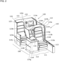
- the aircraft seat structure 100 will be described as a single unit having a first seat unit 110 and a second seat unit 120 coupled to the rear side of the first seat unit 110.
- the first seat unit 110 includes a first seat region 111 including a seat 113, and a first side region 112 provided laterally adjacent to the seat 113.
- the seat 113 can be changed in form between an upright state in which the backrest is upright and a reclining state in which the backrest is tilted to approach a horizontal state.
- the second seat unit 120 includes a second seat region 121 including a seat 123, and a first side region 122 provided laterally adjacent to the seat 122.
- the seat 123 can be changed in form between an upright state in which the backrest is upright and a reclining state in which the backrest is tilted to approach a horizontal state.
- the first side region 112 of the first seat unit 110 is provided on the right side of the seat 113 along a direction that intersects the traveling direction of the aircraft
- the second side region 122 of the second seat unit 120 is provided on the left side of the seat 123 along a direction that intersects the traveling direction of the aircraft.
- the first seat unit 110 and the second seat unit 120 be formed such that their respective seat areas and side areas have the same size.
- the seats 113 and 123 can have a common shape, and the parts can be standardized.
- the seat 113 includes a seating portion 113a and a backrest 113b that is tiltable with respect to the seating portion 113a.
- the seat 123 includes a seating portion 123a and a backrest 123b that is tiltable with respect to the seating portion 123a.
- a partition wall 114 integrally formed of a composite material is disposed between the first seat unit 110 and the second seat unit 120.
- the partition wall 114 includes, in a continuously joined fashion, a seat side surface portion 114a that surrounds the side portion of the seat 113, a seat back surface portion 114b that covers the back surface of the seat 113, an intermediate wall 114c formed between the seat 113 and the first side region 112, a housing portion 114d forming the first side region 112, and a monitor mounting wall 114e ( FIG. 2 ) extending from the housing portion 114d to the second seat unit 120 side.
- the interior of the housing portion 114d is separated from the first seat unit 110 by the intermediate wall 114c, a front panel 114f, a side panel 114g, and a top panel 114h.
- the second seat unit 120 side of the housing portion 114d is open, and the internal space of the housing portion 114d can be accessed from here.
- the housing portion 114d serves as a partition, and the first side region 112 is joined in a state in which a part of the second seat region 121 is inserted.
- a sound absorbing material or the like may be attached to the inner wall of the housing portion 114d.
- a foot rest portion 115 supported at both ends by the intermediate wall 114c and the side panel 114g is disposed inside the housing portion 114d.
- the lower portion of the foot rest portion 115 can be used as a space for placing small baggage or the like.
- a side table 116 that can be used by a passenger seated on the seat 113 is disposed on the top panel 114h of the housing portion 114d ( FIG. 2 ).
- the monitor mounting wall 114e extends at an incline from the upper end edge of the housing portion 114d on the second seat unit 120 side toward the second seat unit 120 side. Since the monitor mounting wall 114e is inclined toward the second seat unit 120, passengers using the first seat unit 110 do not feel feelings of oppressiveness.
- the back surface (the lower surface) of the monitor mounting wall 114e is an inclined surface 114i tilted so as to fall toward the second seat unit 120 side.
- the inclined surface 114i is connected to the lower surface of the top panel 114h of the housing portion 114d.
- a partition plate 114j is supported on the side edge of the monitor mounting wall 114e and extends in the same direction as the side panel 114g of the housing portion 114d.
- the inclination angle of the inclined surface 114i is preferably within 45 degrees with respect to the horizontal plane.
- an upper edge of a monitor 117 with its screen facing the second seat unit 120 side is attached via a hinge (not shown in the figure).
- a hinge not shown in the figure.
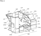
- the monitor 117 can be manually or electrically displaced between the erect position illustrated in FIG. 1 and the tilted position illustrated in FIG. 4 . In the tilted position, the monitor 117 extends in a direction along the inclined surface 114i.
- the inclined surface 114i may be provided with a rectangular concave portion 114k into which the electronic component accommodating portion on the back surface of the monitor 117 fits when the monitor 117 is tilted ( FIG. 1 ). In this way, the difference in height between the screen of the monitor 117 and the inclined surface 114i can be reduced.
- the monitor 117 When the monitor 117 is tilted to the erect position as illustrated in FIG. 1 , a triangular, tubular space is formed between the monitor 117 and the inclined surface 114i. For this reason, in the case that a passenger's head falls forward and hits the monitor 117 as a result of the aircraft shaking, for example, the monitor 117 can retract with a light force, thereby enhancing safety. It should be noted that, although not illustrated in the figures, when the monitor 117 in the erect position is pushed by a force equal to or greater than a threshold value from the second seat unit 120 side, the monitor 117 may be unlocked and the monitor 117 may automatically retract to the position illustrated in FIG. 4 by the force of a spring.
- a pocket 114m for accommodating headphones or the like, a light 114n for the first seat unit 110, and an accommodation portion 114p for accommodating a remote controller for in-flight entertainment or the like is formed on the front surface of the monitor mounting wall 114e.
- a partition wall 124 integrally formed of composite materials is disposed between the second seat unit 120 and the rear side seat unit thereof (not illustrated in the Figure).
- the partition wall 124 which has a shape that is a mirror image of the partition wall 114, includes a seat side surface portion 124a that surrounds the side portion of the seat 123, a seat back surface portion 124b that surrounds the back surface of the seat 123, an intermediate wall 124c ( FIG. 2 ) formed between the seat 123 and the second side region 122, a housing portion 124d forming the second side region 122, and a monitor mounting wall 124e extending rearward from the housing portion 124d. It should be noted that a redundant description of configurations similar to that of the first seat unit 110 will be omitted.
- the housing portion 124d has a similar configuration to the housing portion 114d
- the monitor mounting wall 124e has a similar configuration to the monitor mounting wall 114e.
- a monitor 127 is tiltably mounted on the monitor mounting wall 124e.
- a passenger control unit PCU equipped with an on/off switch for the monitor 117 viewed by the passenger sitting on the seat 123, a switch for selecting a channel, a knob for changing a sound volume, a switch for performing tilting in the case that the monitor is configured to be tilted by electric power, a switch for changing the seat 123 to an upright state or a reclining state, and the like is disposed below the side table 126 so as to face the seat 123 ( FIG. 5 ). It should be noted that a similar passenger control unit is also arranged for the first seat unit 110.
- the seat 123 of the second seat unit 120 can be form changed between an upright state and a reclining state by a driving mechanism (not illustrated in the figure) by operating the passenger control unit PCU.
- a driving mechanism can use, for example, the technique of Japanese Translation of PCT International Application Publication No. 2010-520117 .
- the backrest 123b is angled at approximately 100 degrees with respect to the seating portion 123a.
- the passenger seated on the seat 123 in this state can see the screen of the monitor 117 while being supported by the backrest 123b.
- the passenger may also place their feet on the foot rest portion 115.
- the seating portion 123a advances toward the housing portion 114d while the backrest 123b approaches the horizontal and enters a state of being close to or in contact with the foot rest portion 115 as illustrated in FIG. 4 .
- the backrest 123b, the seating portion 123a, and the foot rest portion 115 are in a substantially flat state.
- the passenger PS can lie on the seat 123 that has been set to the reclining state, and the monitor 117 can be displaced to a position parallel to the inclined surface 114i as illustrated in FIG. 4 by the hand of the passenger or by operation of the passenger control unit PCU. In this way, even when the passenger PS is lying down, since the face of the passenger PS faces the monitor 117, the images displayed on the monitor 117 can be naturally viewed.
- the passenger PS can take a relaxed posture such as crossing their legs or curling their body and tilting their head forward without being obstructed by the monitor 117, thereby achieving a comfortable flight.
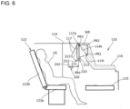
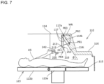
- FIG. 6 and FIG. 7 are side views illustrating the aircraft seat structure according to the first embodiment as seen from the side.
- FIG. 6 illustrates the seat 123 of the second seat region in the upright state.
- FIG. 7 illustrates the seat 123 of the second seat region in the reclining state. It should be noted that the same reference numerals are assigned to the same configurations as those of the above-described embodiment, and a repetitive description thereof is omitted.
- the monitor 117 is rotatably attached to the upper end of the inclined surface 114i of the first seat unit 110 via a rotation shaft 117a. It is assumed that the monitor 117 is constantly urged clockwise about the rotation shaft 117a in FIG. 6 and FIG. 7 by a spring (not illustrated in the figure) having a weaker urging force than a spiral spring 234 (to be described later). Near the lower end of the monitor 117, a locking device 210 is attached to the partition wall 114.
- the locking device 210 includes a swing shaft 211 that extends in a direction perpendicular to the paper surface and can swing with respect to the partition wall 114, a swing plate 212 that extends in the radial direction from the swing shaft 211, and a locking portion 213 protruding upward from both ends of the swing plate 212.
- the end of the wire WR is connected to the lower end of the back surface of the monitor 117.
- the wire WR is connected to a winding mechanism 220 via pulleys PR1, PR2, PR3, and PR4 that are rotatably attached to the partition wall 114.
- the monitor 117 is biased clockwise by a spring (not illustrated in the figure), if the tension of the wire WR is not applied, the monitor 117 will tilt to the tilted end illustrated by the dotted line in FIG. 6 or the erect position illustrated by the solid line in FIG. 7 .
- FIG. 8 is a schematic view of the winding mechanism 220.
- the winding mechanism 220 that constitutes the driving mechanism includes a rotating portion 230 and a lever portion 240.
- the rotating portion 230 includes a fixed shaft 231 which is fixed to the partition wall 114, a toothed disk 232 which rotates about the fixed shaft 231, a drum 233 which is coaxially connected to the toothed disk 232, and a spiral spring 234 that connects the fixed shaft 231 and the drum 233.
- a plurality of teeth 235 having a short inclined surface 235a and a long inclined surface 235b are formed adjacent to each other in the circumferential direction.
- the short inclined surface 235a extends substantially along the radial direction of the toothed disk 232.
- the end of the wire WR is connected to the outer circumference of the drum 233, and the wire WR is wound around the outer circumference of the drum 233.
- the lever portion 240 includes a lever shaft 241 fixed to the partition wall 114, and a lever (an operation unit) 242 that can swing around the lever shaft 241.
- the lever 242 is formed with a claw portion 243 protruding toward the toothed disk 232 and a convex portion 244 protruding downward.
- the claw portion 243 can be engaged with the short inclined surface 235a of the teeth 235 of the toothed disk 232.
- a spring 245 is arranged between the convex portion 244 and a portion of the partition wall 114, and the convex portion 244 is pressed toward a contact locking portion 114s by the urging force of the spring 245.
- the toothed disk 232 and the drum 233 are urged counterclockwise in FIG. 8 by the spiral spring 234, and in a free state, the claw portion 243 of the lever 242 comes into contact with the short inclined surface 235a of the teeth 235 of the toothed disk 232, such that the toothed disk 232 is
- the monitor inclination angle is considered to be zero (the erect position), in the case that the monitor 117 is tilted toward a user US who views the screen of the monitor 117, the monitor inclination angle is considered to be in a negative angle range, and in the case that the monitor 117 is tilted away from the user US, the monitor inclination angle is considered to be in a positive angle range.
- the swing shaft 211 of the locking device 210 swings counterclockwise so that the locking portion 213 comes into contact with the back surface of the monitor 117, which is in the erect position. This is referred to as the upright position.
- the locking device 210 may be swung to the upright position by an actuator or the like connected to the seat 123, or alternatively swung to the upright position in response to the movement of the seat 123 by the link mechanism.
- the wire WR can be freely pulled out, such that the operation of the user who pulls out the monitor 117 forward is not hindered.
- the toothed disk 232 rotates counterclockwise due to the urging force of the spiral spring 234, but the claw portion 243 engages with any of the short inclined surfaces 235a, whereby the rotation of the drum 233 is locked so that the monitor 117 stays in that position.
- the user US tilts the lever 242 from the solid line position to the dashed line position against the urging force of the spring 245.
- the claw portion 243 of the lever 242 disengages from the short inclined surface 235a of the teeth 235 of the toothed disk 232, and the urging force of the spiral spring 234 causes the toothed disk 232 and the drum 233 to begin to rotate counterclockwise in FIG. 8 .
- the wire WR is pulled, drawing the lower end of the monitor 117 toward the inclined surface 114i, and the inclination angle of the monitor 117 approaches zero.
- the urging force of the spring 245 causes the lever 242 to return to its original position, and the claw portion 243 engages with the short inclined surface 235a, thereby stopping the rotation of the toothed disk 232 and the drum 233, and the monitor 117 remains in that position.
- the locking portion 213 of the locking device 210 eventually hits the back of the monitor 117 to prevent further tilting, and the monitor 117 is engaged in a state where the inclination angle is zero.
- the lever 242 can be tilted by remote control using, for example, an electromagnetic solenoid.
- the seat 123 is returned to the upright state in order to ensure safety.
- the cabin attendant can operate switches (not illustrated in the figure) to tilt the levers 242 of each seat all at once.
- the swing shaft 211 of the locking device 210 swings clockwise so that the locking portion 213 comes into contact with the front surface of the monitor 117 in an erect position. This is referred to as the reclining portion.
- the lever 242 is positioned with the reach of the user US lying on the seat 123.
- the toothed disk 232 is rotated counterclockwise in FIG. 8 by the urging force of the spiral spring 234, the wire WR is pulled, and the monitor 117 can be tilted in a direction in which the inclination angle is in the positive angle range.
- the pulling of the wire WR is interrupted, and the monitor 117 remains in that position as described above.
- the user US can view the screen of the monitor 117 at a desired monitor inclination angle in the positive angle range. If the user US continues to pull the lever 242, the monitor 117 eventually tilts to a position in which it is accommodated in the concave portion 114k of the inclined surface 114i.
- monitor 117 When the monitor 117 is accommodated in the concave portion 114k, further tilting is prevented, and the monitor 117 is locked at a monitor inclination angle which is the maximum value of the positive angle range (here, +35 degrees).
- the monitor inclination angle that is the maximum value of the positive angle range is preferably 30 degrees to 45 degrees in order to ensure the visibility of the monitor 117.
- the inclination angle ⁇ of the inclined surface 114i with respect to the floor surface is equal to the maximum value of the monitor inclination angle in order to ensure effective utilization of the space and improvement of design.
- the monitor 117 can be reached, and the monitor 117 can be grasped and returned to the erect position.
- the monitor 117 may be tiltable between two positions of an erect position and a tilted position, may be locked at a plurality of tilted positions between the erect position and the tilted position, or alternatively may be configured to be steplessly displaced and locked at an arbitrary position.
- Aircraft 100 Aircraft Seat Structure, 110 First Seat Unit, 120 Second Seat Unit, 111, 121 Seat Region, 112, 122 Side Region, 113, 123 Seat, 114, 124 Partition Wall, Monitor 117,127, 210 Locking Device, 220 Winding Mechanism
Landscapes
- Engineering & Computer Science (AREA)
- Aviation & Aerospace Engineering (AREA)
- Seats For Vehicles (AREA)
- Passenger Equipment (AREA)
- Chairs For Special Purposes, Such As Reclining Chairs (AREA)
Claims (8)
- Aufbau eines Flugzeugsitzes (100), umfassend:eine erste Sitzeinheit (110) mit einem ersten Sitzbereich (111), in dem Passagiere sitzen können, und einem ersten Seitenbereich (112) angrenzend in einer Richtung rechtwinklig zu einer Längsrichtung des ersten Sitzbereichs (111); undeine zweite Sitzeinheit (120) mit einem zweiten Sitzbereich (121), in dem Passagiere sitzen können, und einem zweiten Seitenbereich (122) angrenzend in einer Richtung rechtwinklig zu einer Längsrichtung des zweiten Sitzbereichs (121);wobei:der erste Seitenbereich (112) auf einer Seite des ersten Sitzbereichs (111) entlang einer Richtung vorgesehen ist, die eine Flugrichtung eines Flugzeugs kreuzt, und der zweite Seitenbereich (122) auf einer anderen Seite des zweiten Sitzbereichs (121) entlang der Richtung vorgesehen ist, die die Flugrichtung des Flugzeugs kreuzt,der erste Seitenbereich (112) und der zweite Sitzbereich (121) in einem Zustand verbunden sind, in dem ein Abschnitt des zweiten Sitzbereichs (121) in den ersten Seitenbereich (112) eingesetzt ist,der erste Seitenbereich (112) und der zweite Seitenbereich (122) durch eine Trennwand (114, 124) getrennt sind,die Trennwand (114, 124) eine schräge Fläche aufweist, die in Richtung der zweiten Sitzeinheit (120) geneigt ist;eine Verriegelungsvorrichtung (210), die an der Trennwand (114, 124) angebracht ist, wobei die Verriegelungsvorrichtung einen Verriegelungsabschnitt (213) umfasst,dadurch gekennzeichnet, dass ein Bildschirm (117, 127) neigbar an der schrägen Fläche angebracht ist,ein Sitz (123) des zweiten Sitzbereichs (121) in seiner Form zwischen einem aufrechten Zustand und einem zurückgelehnten Zustand verändert werden kann und der Bildschirm (117, 127) zwischen einer geneigten Stellung entsprechend dem aufrechten Zustand und einer geneigten Stellung entsprechend dem zurückgelehnten Zustand verstellt werden kann;wenn sich der Sitz (123) des zweiten Sitzbereichs (121) im aufrechten Zustand befindet, der Verriegelungsabschnitt (213) der Verriegelungsvorrichtung (210) des Sitzes (123) des zweiten Sitzbereichs (121) dazu ausgelegt ist, an einer Rückfläche des Bildschirms (117, 127) anzuliegen; undder Verriegelungsabschnitt (213) der Verriegelungsvorrichtung (210) des Sitzes (123) des zweiten Sitzbereichs (121) dazu ausgelegt ist, an einer Vorderfläche des Bildschirms (117, 127) anzuliegen, wenn sich der Sitz (123) des zweiten Sitzbereichs (121) im zurückgelehnten Zustand befindet.
- Aufbau eines Flugzeugsitzes (100) nach Anspruch 1, wobei:die Trennwand (114, 124) einen Gehäuseabschnitt aufweist, der den ersten Seitenbereich (112) und den zweiten Sitzbereich (121) trennt; unddie schräge Fläche eine Rückfläche einer Montagewand ist, die sich von dem Gehäuseabschnitt in Richtung der zweiten Sitzeinheit (120) erstreckt.
- Aufbau eines Flugzeugsitzes (100) nach Anspruch 2, wobei:
ein Fußstützenabschnitt in dem Gehäuseabschnitt ausgebildet ist. - Aufbau eines Flugzeugsitzes (100) nach einem der Ansprüche 1 bis 3, wobei:wenn der Bildschirm (117, 127) in die geneigte Stellung entsprechend dem aufrechten Zustand verstellt wird, ein Raum zwischen dem Bildschirm (117, 127) und der schrägen Fläche gebildet wird; undwenn der Bildschirm (117, 127) in die geneigte Stellung entsprechend dem zurückgelehnten Zustand verstellt wird, sich der Bildschirm (117, 127) in eine Richtung entlang der schrägen Fläche erstreckt.
- Aufbau eines Flugzeugsitzes nach einem der Ansprüche 1 bis 4, wobei:wenn sich der Sitz (123) des zweiten Sitzbereichs (121) im aufrechten Zustand befindet, der Bildschirm (117, 127) in einem negativen Winkelbereich geneigt werden kann; undwenn sich der Sitz (123) des zweiten Sitzbereichs (121) im zurückgelehnten Zustand befindet, der Bildschirm (117, 127) in einem positiven Winkelbereich geneigt werden kann.
- Aufbau eines Flugzeugsitzes (100) nach einem der Ansprüche 1 bis 5, ferner umfassend:
einen Antriebsmechanismus zum Neigen des Bildschirms (117, 127) in eine vorbestimmte Stellung. - Aufbau eines Flugzeugsitzes (100) nach Anspruch 6, wobei:
eine Betätigungseinheit des Antriebsmechanismus an einer Position angeordnet ist, die für eine Hand eines Benutzers, der auf einem Sitz in einem zurückgelehnten Zustand liegt, zugänglich ist. - Aufbau eines Flugzeugsitzes (100) nach einem der Ansprüche 1 bis 7, wobei:
die schräge Fläche einen konkaven Abschnitt zum Aufnehmen eines Abschnitts des Bildschirms (117, 127) aufweist.
Applications Claiming Priority (2)
| Application Number | Priority Date | Filing Date | Title |
|---|---|---|---|
| JP2019059826 | 2019-03-27 | ||
| PCT/JP2020/011075 WO2020195945A1 (ja) | 2019-03-27 | 2020-03-13 | 航空機用シート構造体 |
Publications (3)
| Publication Number | Publication Date |
|---|---|
| EP3950504A1 EP3950504A1 (de) | 2022-02-09 |
| EP3950504A4 EP3950504A4 (de) | 2022-11-23 |
| EP3950504B1 true EP3950504B1 (de) | 2024-07-31 |
Family
ID=72611441
Family Applications (1)
| Application Number | Title | Priority Date | Filing Date |
|---|---|---|---|
| EP20779709.3A Active EP3950504B1 (de) | 2019-03-27 | 2020-03-13 | Aufbau eines flugzeugsitzes |
Country Status (4)
| Country | Link |
|---|---|
| US (1) | US11731764B2 (de) |
| EP (1) | EP3950504B1 (de) |
| JP (1) | JP6949245B2 (de) |
| WO (1) | WO2020195945A1 (de) |
Families Citing this family (8)
| Publication number | Priority date | Publication date | Assignee | Title |
|---|---|---|---|---|
| GB2586043B (en) * | 2019-07-31 | 2023-05-10 | Safran Seats Gb Ltd | Aircraft passenger seat unit with movable panel |
| DE102020108436A1 (de) * | 2020-03-26 | 2021-09-30 | Recaro Aircraft Seating Gmbh & Co. Kg | Flugzeugsitzanordnung |
| USD984155S1 (en) * | 2020-09-24 | 2023-04-25 | Panasonic Intellectual Property Management Co., Ltd. | Combined transmissive display and airplane seat unit |
| USD990904S1 (en) * | 2020-09-24 | 2023-07-04 | Panasonic Intellectual Property Management Co., Ltd. | Combined transmissive display and airplane seat unit |
| USD990181S1 (en) * | 2020-09-24 | 2023-06-27 | Panasonic Intellectual Property Management Co., Ltd. | Combined transmissive display and airplane seat unit |
| USD989500S1 (en) * | 2020-09-24 | 2023-06-20 | Panasonic Intellectual Property Management Co., Ltd. | Combined transmissive display and airplane seat unit |
| US20240351689A1 (en) * | 2023-04-24 | 2024-10-24 | B/E Aerospace, Inc. | Passenger seating system |
| DE102023122439A1 (de) * | 2023-08-22 | 2025-02-27 | Recaro Aircraft Seating Gmbh & Co. Kg | Flugzeugsitzsystem |
Family Cites Families (12)
| Publication number | Priority date | Publication date | Assignee | Title |
|---|---|---|---|---|
| US6227489B1 (en) * | 1998-05-15 | 2001-05-08 | Koito Industries, Ltd. | Aircraft seat apparatus |
| RU2255372C2 (ru) | 2003-08-26 | 2005-06-27 | Баженов Владимир Александрович | Способ передачи и обработки информации при проведении соревнований в области интеллектуальных игр между удаленными друг от друга игроками и система для его осуществления |
| JP2008279155A (ja) * | 2007-05-14 | 2008-11-20 | Panasonic Corp | 画像表示装置 |
| GB2490095B (en) * | 2011-04-01 | 2017-05-10 | Zodiac Seats Uk Ltd | Aircraft seat arrangement including table |
| WO2012140515A1 (en) * | 2011-04-15 | 2012-10-18 | Societe Industrielle Et Commerciale De Materiel Aeronautique | Passenger seating arrangements |
| GB2500258B (en) * | 2012-03-16 | 2019-05-08 | Zodiac Seats Uk Ltd | High density aircraft seat arrangement |
| DE102013011514A1 (de) * | 2013-05-07 | 2014-11-13 | Recaro Aircraft Seating Gmbh & Co. Kg | Flugzeugsitz |
| EP3581496B1 (de) * | 2013-10-24 | 2021-09-08 | Safran Seats | Sitzeinheit für eine fahrzeugkabine |
| GB2523309B (en) * | 2014-02-12 | 2015-12-23 | British Airways Plc | Aircraft passenger seating arrangements |
| FR3049578B1 (fr) * | 2016-03-31 | 2019-08-16 | Stelia Aerospace | Ensemble de sieges a fauteuils agences en quinconce |
| EP3437996A4 (de) | 2016-04-01 | 2019-11-06 | Jamco Corporation | Aufbau eines flugzeugsitzes |
| WO2020089442A1 (fr) * | 2018-11-02 | 2020-05-07 | Style & Design Group | Unite de siege passager pour une cabine d'aeronef |
-
2020
- 2020-03-13 EP EP20779709.3A patent/EP3950504B1/de active Active
- 2020-03-13 JP JP2020552432A patent/JP6949245B2/ja active Active
- 2020-03-13 WO PCT/JP2020/011075 patent/WO2020195945A1/ja not_active Ceased
- 2020-03-13 US US17/440,782 patent/US11731764B2/en active Active
Also Published As
| Publication number | Publication date |
|---|---|
| JPWO2020195945A1 (ja) | 2021-04-30 |
| US20220161929A1 (en) | 2022-05-26 |
| US11731764B2 (en) | 2023-08-22 |
| JP6949245B2 (ja) | 2021-10-13 |
| EP3950504A4 (de) | 2022-11-23 |
| WO2020195945A1 (ja) | 2020-10-01 |
| EP3950504A1 (de) | 2022-02-09 |
Similar Documents
| Publication | Publication Date | Title |
|---|---|---|
| EP3950504B1 (de) | Aufbau eines flugzeugsitzes | |
| CN1114547C (zh) | 飞机的座位组合件 | |
| US6669141B2 (en) | Aircraft passenger cabin with rotatable passenger seats | |
| JP3990986B2 (ja) | 調節可能なシート | |
| CN106114870B (zh) | 乘客座椅组件及其多个方面 | |
| JP5248325B2 (ja) | 航空機の乗客用座席 | |
| EP2391541B1 (de) | Sitzanordnung, sitzeinheit, tisch mit ablage und sitzsystem | |
| CN105338859B (zh) | 具有下降扶手组件的乘客座位 | |
| US8297554B2 (en) | Arrangement of a first and a second furnishing | |
| EP3277583B1 (de) | Verstellbare kopfstütze mit möglichkeit für seitwärtsneigung und zurückgezogenheit | |
| US20130242523A1 (en) | Deployable in-flight entertainment monitor | |
| AU2012351859A1 (en) | Vehicle seat | |
| CN110198891A (zh) | 具有可收起扶手的乘客就座装置 | |
| US10370109B2 (en) | Non-intrusive and reclining seating arrangement for an airplane or other means of transportation | |
| US8851568B2 (en) | Retractable passenger seat | |
| US20150314713A1 (en) | Vehicle Seat | |
| EP2900552B1 (de) | Flugzeug-ablageschrank | |
| US12552538B2 (en) | Seat assembly | |
| CN114466795B (zh) | 非侵入式固定显示器护罩 | |
| US12409938B2 (en) | Seat arrangements, in particular for an aircraft cabin | |
| US11801941B2 (en) | Suite with improved arrangement, in particular for an aircraft cabin |
Legal Events
| Date | Code | Title | Description |
|---|---|---|---|
| STAA | Information on the status of an ep patent application or granted ep patent |
Free format text: STATUS: THE INTERNATIONAL PUBLICATION HAS BEEN MADE |
|
| PUAI | Public reference made under article 153(3) epc to a published international application that has entered the european phase |
Free format text: ORIGINAL CODE: 0009012 |
|
| STAA | Information on the status of an ep patent application or granted ep patent |
Free format text: STATUS: REQUEST FOR EXAMINATION WAS MADE |
|
| 17P | Request for examination filed |
Effective date: 20210923 |
|
| AK | Designated contracting states |
Kind code of ref document: A1 Designated state(s): AL AT BE BG CH CY CZ DE DK EE ES FI FR GB GR HR HU IE IS IT LI LT LU LV MC MK MT NL NO PL PT RO RS SE SI SK SM TR |
|
| DAV | Request for validation of the european patent (deleted) | ||
| DAX | Request for extension of the european patent (deleted) | ||
| A4 | Supplementary search report drawn up and despatched |
Effective date: 20221021 |
|
| RIC1 | Information provided on ipc code assigned before grant |
Ipc: B64D 11/00 20060101ALI20221017BHEP Ipc: B60N 3/06 20060101ALI20221017BHEP Ipc: B60N 3/00 20060101ALI20221017BHEP Ipc: B60N 2/22 20060101ALI20221017BHEP Ipc: B60N 2/01 20060101ALI20221017BHEP Ipc: B64D 11/06 20060101AFI20221017BHEP |
|
| GRAP | Despatch of communication of intention to grant a patent |
Free format text: ORIGINAL CODE: EPIDOSNIGR1 |
|
| STAA | Information on the status of an ep patent application or granted ep patent |
Free format text: STATUS: GRANT OF PATENT IS INTENDED |
|
| INTG | Intention to grant announced |
Effective date: 20240306 |
|
| GRAS | Grant fee paid |
Free format text: ORIGINAL CODE: EPIDOSNIGR3 |
|
| GRAA | (expected) grant |
Free format text: ORIGINAL CODE: 0009210 |
|
| STAA | Information on the status of an ep patent application or granted ep patent |
Free format text: STATUS: THE PATENT HAS BEEN GRANTED |
|
| P01 | Opt-out of the competence of the unified patent court (upc) registered |
Effective date: 20240524 |
|
| AK | Designated contracting states |
Kind code of ref document: B1 Designated state(s): AL AT BE BG CH CY CZ DE DK EE ES FI FR GB GR HR HU IE IS IT LI LT LU LV MC MK MT NL NO PL PT RO RS SE SI SK SM TR |
|
| REG | Reference to a national code |
Ref country code: CH Ref legal event code: EP Ref country code: GB Ref legal event code: FG4D |
|
| REG | Reference to a national code |
Ref country code: DE Ref legal event code: R096 Ref document number: 602020034936 Country of ref document: DE |
|
| REG | Reference to a national code |
Ref country code: IE Ref legal event code: FG4D |
|
| REG | Reference to a national code |
Ref country code: LT Ref legal event code: MG9D |
|
| REG | Reference to a national code |
Ref country code: NL Ref legal event code: MP Effective date: 20240731 |
|
| PG25 | Lapsed in a contracting state [announced via postgrant information from national office to epo] |
Ref country code: PT Free format text: LAPSE BECAUSE OF FAILURE TO SUBMIT A TRANSLATION OF THE DESCRIPTION OR TO PAY THE FEE WITHIN THE PRESCRIBED TIME-LIMIT Effective date: 20241202 |
|
| REG | Reference to a national code |
Ref country code: AT Ref legal event code: MK05 Ref document number: 1708260 Country of ref document: AT Kind code of ref document: T Effective date: 20240731 |
|
| PG25 | Lapsed in a contracting state [announced via postgrant information from national office to epo] |
Ref country code: PT Free format text: LAPSE BECAUSE OF FAILURE TO SUBMIT A TRANSLATION OF THE DESCRIPTION OR TO PAY THE FEE WITHIN THE PRESCRIBED TIME-LIMIT Effective date: 20241202 |
|
| PG25 | Lapsed in a contracting state [announced via postgrant information from national office to epo] |
Ref country code: NO Free format text: LAPSE BECAUSE OF FAILURE TO SUBMIT A TRANSLATION OF THE DESCRIPTION OR TO PAY THE FEE WITHIN THE PRESCRIBED TIME-LIMIT Effective date: 20241031 |
|
| PG25 | Lapsed in a contracting state [announced via postgrant information from national office to epo] |
Ref country code: FI Free format text: LAPSE BECAUSE OF FAILURE TO SUBMIT A TRANSLATION OF THE DESCRIPTION OR TO PAY THE FEE WITHIN THE PRESCRIBED TIME-LIMIT Effective date: 20240731 Ref country code: NL Free format text: LAPSE BECAUSE OF FAILURE TO SUBMIT A TRANSLATION OF THE DESCRIPTION OR TO PAY THE FEE WITHIN THE PRESCRIBED TIME-LIMIT Effective date: 20240731 Ref country code: PL Free format text: LAPSE BECAUSE OF FAILURE TO SUBMIT A TRANSLATION OF THE DESCRIPTION OR TO PAY THE FEE WITHIN THE PRESCRIBED TIME-LIMIT Effective date: 20240731 Ref country code: GR Free format text: LAPSE BECAUSE OF FAILURE TO SUBMIT A TRANSLATION OF THE DESCRIPTION OR TO PAY THE FEE WITHIN THE PRESCRIBED TIME-LIMIT Effective date: 20241101 |
|
| PG25 | Lapsed in a contracting state [announced via postgrant information from national office to epo] |
Ref country code: BG Free format text: LAPSE BECAUSE OF FAILURE TO SUBMIT A TRANSLATION OF THE DESCRIPTION OR TO PAY THE FEE WITHIN THE PRESCRIBED TIME-LIMIT Effective date: 20240731 |
|
| PG25 | Lapsed in a contracting state [announced via postgrant information from national office to epo] |
Ref country code: LV Free format text: LAPSE BECAUSE OF FAILURE TO SUBMIT A TRANSLATION OF THE DESCRIPTION OR TO PAY THE FEE WITHIN THE PRESCRIBED TIME-LIMIT Effective date: 20240731 |
|
| PG25 | Lapsed in a contracting state [announced via postgrant information from national office to epo] |
Ref country code: AT Free format text: LAPSE BECAUSE OF FAILURE TO SUBMIT A TRANSLATION OF THE DESCRIPTION OR TO PAY THE FEE WITHIN THE PRESCRIBED TIME-LIMIT Effective date: 20240731 Ref country code: IS Free format text: LAPSE BECAUSE OF FAILURE TO SUBMIT A TRANSLATION OF THE DESCRIPTION OR TO PAY THE FEE WITHIN THE PRESCRIBED TIME-LIMIT Effective date: 20241130 |
|
| PG25 | Lapsed in a contracting state [announced via postgrant information from national office to epo] |
Ref country code: HR Free format text: LAPSE BECAUSE OF FAILURE TO SUBMIT A TRANSLATION OF THE DESCRIPTION OR TO PAY THE FEE WITHIN THE PRESCRIBED TIME-LIMIT Effective date: 20240731 |
|
| PG25 | Lapsed in a contracting state [announced via postgrant information from national office to epo] |
Ref country code: RS Free format text: LAPSE BECAUSE OF FAILURE TO SUBMIT A TRANSLATION OF THE DESCRIPTION OR TO PAY THE FEE WITHIN THE PRESCRIBED TIME-LIMIT Effective date: 20241031 Ref country code: ES Free format text: LAPSE BECAUSE OF FAILURE TO SUBMIT A TRANSLATION OF THE DESCRIPTION OR TO PAY THE FEE WITHIN THE PRESCRIBED TIME-LIMIT Effective date: 20240731 |
|
| PG25 | Lapsed in a contracting state [announced via postgrant information from national office to epo] |
Ref country code: RS Free format text: LAPSE BECAUSE OF FAILURE TO SUBMIT A TRANSLATION OF THE DESCRIPTION OR TO PAY THE FEE WITHIN THE PRESCRIBED TIME-LIMIT Effective date: 20241031 Ref country code: PL Free format text: LAPSE BECAUSE OF FAILURE TO SUBMIT A TRANSLATION OF THE DESCRIPTION OR TO PAY THE FEE WITHIN THE PRESCRIBED TIME-LIMIT Effective date: 20240731 Ref country code: NO Free format text: LAPSE BECAUSE OF FAILURE TO SUBMIT A TRANSLATION OF THE DESCRIPTION OR TO PAY THE FEE WITHIN THE PRESCRIBED TIME-LIMIT Effective date: 20241031 Ref country code: NL Free format text: LAPSE BECAUSE OF FAILURE TO SUBMIT A TRANSLATION OF THE DESCRIPTION OR TO PAY THE FEE WITHIN THE PRESCRIBED TIME-LIMIT Effective date: 20240731 Ref country code: LV Free format text: LAPSE BECAUSE OF FAILURE TO SUBMIT A TRANSLATION OF THE DESCRIPTION OR TO PAY THE FEE WITHIN THE PRESCRIBED TIME-LIMIT Effective date: 20240731 Ref country code: IS Free format text: LAPSE BECAUSE OF FAILURE TO SUBMIT A TRANSLATION OF THE DESCRIPTION OR TO PAY THE FEE WITHIN THE PRESCRIBED TIME-LIMIT Effective date: 20241130 Ref country code: HR Free format text: LAPSE BECAUSE OF FAILURE TO SUBMIT A TRANSLATION OF THE DESCRIPTION OR TO PAY THE FEE WITHIN THE PRESCRIBED TIME-LIMIT Effective date: 20240731 Ref country code: GR Free format text: LAPSE BECAUSE OF FAILURE TO SUBMIT A TRANSLATION OF THE DESCRIPTION OR TO PAY THE FEE WITHIN THE PRESCRIBED TIME-LIMIT Effective date: 20241101 Ref country code: FI Free format text: LAPSE BECAUSE OF FAILURE TO SUBMIT A TRANSLATION OF THE DESCRIPTION OR TO PAY THE FEE WITHIN THE PRESCRIBED TIME-LIMIT Effective date: 20240731 Ref country code: ES Free format text: LAPSE BECAUSE OF FAILURE TO SUBMIT A TRANSLATION OF THE DESCRIPTION OR TO PAY THE FEE WITHIN THE PRESCRIBED TIME-LIMIT Effective date: 20240731 Ref country code: BG Free format text: LAPSE BECAUSE OF FAILURE TO SUBMIT A TRANSLATION OF THE DESCRIPTION OR TO PAY THE FEE WITHIN THE PRESCRIBED TIME-LIMIT Effective date: 20240731 Ref country code: AT Free format text: LAPSE BECAUSE OF FAILURE TO SUBMIT A TRANSLATION OF THE DESCRIPTION OR TO PAY THE FEE WITHIN THE PRESCRIBED TIME-LIMIT Effective date: 20240731 |
|
| PG25 | Lapsed in a contracting state [announced via postgrant information from national office to epo] |
Ref country code: DK Free format text: LAPSE BECAUSE OF FAILURE TO SUBMIT A TRANSLATION OF THE DESCRIPTION OR TO PAY THE FEE WITHIN THE PRESCRIBED TIME-LIMIT Effective date: 20240731 Ref country code: RO Free format text: LAPSE BECAUSE OF FAILURE TO SUBMIT A TRANSLATION OF THE DESCRIPTION OR TO PAY THE FEE WITHIN THE PRESCRIBED TIME-LIMIT Effective date: 20240731 Ref country code: SM Free format text: LAPSE BECAUSE OF FAILURE TO SUBMIT A TRANSLATION OF THE DESCRIPTION OR TO PAY THE FEE WITHIN THE PRESCRIBED TIME-LIMIT Effective date: 20240731 |
|
| PG25 | Lapsed in a contracting state [announced via postgrant information from national office to epo] |
Ref country code: EE Free format text: LAPSE BECAUSE OF FAILURE TO SUBMIT A TRANSLATION OF THE DESCRIPTION OR TO PAY THE FEE WITHIN THE PRESCRIBED TIME-LIMIT Effective date: 20240731 |
|
| PG25 | Lapsed in a contracting state [announced via postgrant information from national office to epo] |
Ref country code: CZ Free format text: LAPSE BECAUSE OF FAILURE TO SUBMIT A TRANSLATION OF THE DESCRIPTION OR TO PAY THE FEE WITHIN THE PRESCRIBED TIME-LIMIT Effective date: 20240731 |
|
| PG25 | Lapsed in a contracting state [announced via postgrant information from national office to epo] |
Ref country code: SK Free format text: LAPSE BECAUSE OF FAILURE TO SUBMIT A TRANSLATION OF THE DESCRIPTION OR TO PAY THE FEE WITHIN THE PRESCRIBED TIME-LIMIT Effective date: 20240731 Ref country code: IT Free format text: LAPSE BECAUSE OF FAILURE TO SUBMIT A TRANSLATION OF THE DESCRIPTION OR TO PAY THE FEE WITHIN THE PRESCRIBED TIME-LIMIT Effective date: 20240731 |
|
| REG | Reference to a national code |
Ref country code: DE Ref legal event code: R097 Ref document number: 602020034936 Country of ref document: DE |
|
| PLBE | No opposition filed within time limit |
Free format text: ORIGINAL CODE: 0009261 |
|
| STAA | Information on the status of an ep patent application or granted ep patent |
Free format text: STATUS: NO OPPOSITION FILED WITHIN TIME LIMIT |
|
| 26N | No opposition filed |
Effective date: 20250501 |
|
| PG25 | Lapsed in a contracting state [announced via postgrant information from national office to epo] |
Ref country code: SE Free format text: LAPSE BECAUSE OF FAILURE TO SUBMIT A TRANSLATION OF THE DESCRIPTION OR TO PAY THE FEE WITHIN THE PRESCRIBED TIME-LIMIT Effective date: 20240731 |
|
| PG25 | Lapsed in a contracting state [announced via postgrant information from national office to epo] |
Ref country code: MC Free format text: LAPSE BECAUSE OF FAILURE TO SUBMIT A TRANSLATION OF THE DESCRIPTION OR TO PAY THE FEE WITHIN THE PRESCRIBED TIME-LIMIT Effective date: 20240731 |
|
| REG | Reference to a national code |
Ref country code: CH Ref legal event code: H13 Free format text: ST27 STATUS EVENT CODE: U-0-0-H10-H13 (AS PROVIDED BY THE NATIONAL OFFICE) Effective date: 20251024 |
|
| PG25 | Lapsed in a contracting state [announced via postgrant information from national office to epo] |
Ref country code: LU Free format text: LAPSE BECAUSE OF NON-PAYMENT OF DUE FEES Effective date: 20250313 |
|
| REG | Reference to a national code |
Ref country code: BE Ref legal event code: MM Effective date: 20250331 |
|
| PG25 | Lapsed in a contracting state [announced via postgrant information from national office to epo] |
Ref country code: BE Free format text: LAPSE BECAUSE OF NON-PAYMENT OF DUE FEES Effective date: 20250331 |
|
| PG25 | Lapsed in a contracting state [announced via postgrant information from national office to epo] |
Ref country code: CH Free format text: LAPSE BECAUSE OF NON-PAYMENT OF DUE FEES Effective date: 20250331 |
|
| PG25 | Lapsed in a contracting state [announced via postgrant information from national office to epo] |
Ref country code: IE Free format text: LAPSE BECAUSE OF NON-PAYMENT OF DUE FEES Effective date: 20250313 |
|
| PGFP | Annual fee paid to national office [announced via postgrant information from national office to epo] |
Ref country code: GB Payment date: 20260202 Year of fee payment: 7 |
|
| PGFP | Annual fee paid to national office [announced via postgrant information from national office to epo] |
Ref country code: DE Payment date: 20260128 Year of fee payment: 7 |
|
| PGFP | Annual fee paid to national office [announced via postgrant information from national office to epo] |
Ref country code: FR Payment date: 20260209 Year of fee payment: 7 |