EP3950331B1 - Verfahren zur herstellung eines dünnplattenförmigen laminats mit filmartiger harzschicht - Google Patents
Verfahren zur herstellung eines dünnplattenförmigen laminats mit filmartiger harzschicht Download PDFInfo
- Publication number
- EP3950331B1 EP3950331B1 EP20776434.1A EP20776434A EP3950331B1 EP 3950331 B1 EP3950331 B1 EP 3950331B1 EP 20776434 A EP20776434 A EP 20776434A EP 3950331 B1 EP3950331 B1 EP 3950331B1
- Authority
- EP
- European Patent Office
- Prior art keywords
- mold
- film
- thin plate
- laminate
- workpiece
- Prior art date
- Legal status (The legal status is an assumption and is not a legal conclusion. Google has not performed a legal analysis and makes no representation as to the accuracy of the status listed.)
- Active
Links
Images


Classifications
-
- B—PERFORMING OPERATIONS; TRANSPORTING
- B32—LAYERED PRODUCTS
- B32B—LAYERED PRODUCTS, i.e. PRODUCTS BUILT-UP OF STRATA OF FLAT OR NON-FLAT, e.g. CELLULAR OR HONEYCOMB, FORM
- B32B37/00—Methods or apparatus for laminating, e.g. by curing or by ultrasonic bonding
- B32B37/0046—Methods or apparatus for laminating, e.g. by curing or by ultrasonic bonding characterised by constructional aspects of the apparatus
- B32B37/0053—Constructional details of laminating machines comprising rollers; Constructional features of the rollers
-
- B—PERFORMING OPERATIONS; TRANSPORTING
- B29—WORKING OF PLASTICS; WORKING OF SUBSTANCES IN A PLASTIC STATE IN GENERAL
- B29C—SHAPING OR JOINING OF PLASTICS; SHAPING OF MATERIAL IN A PLASTIC STATE, NOT OTHERWISE PROVIDED FOR; AFTER-TREATMENT OF THE SHAPED PRODUCTS, e.g. REPAIRING
- B29C33/00—Moulds or cores; Details thereof or accessories therefor
- B29C33/34—Moulds or cores; Details thereof or accessories therefor movable, e.g. to or from the moulding station
-
- B—PERFORMING OPERATIONS; TRANSPORTING
- B29—WORKING OF PLASTICS; WORKING OF SUBSTANCES IN A PLASTIC STATE IN GENERAL
- B29C—SHAPING OR JOINING OF PLASTICS; SHAPING OF MATERIAL IN A PLASTIC STATE, NOT OTHERWISE PROVIDED FOR; AFTER-TREATMENT OF THE SHAPED PRODUCTS, e.g. REPAIRING
- B29C33/00—Moulds or cores; Details thereof or accessories therefor
- B29C33/42—Moulds or cores; Details thereof or accessories therefor characterised by the shape of the moulding surface, e.g. ribs or grooves
- B29C33/424—Moulding surfaces provided with means for marking or patterning
-
- B—PERFORMING OPERATIONS; TRANSPORTING
- B29—WORKING OF PLASTICS; WORKING OF SUBSTANCES IN A PLASTIC STATE IN GENERAL
- B29C—SHAPING OR JOINING OF PLASTICS; SHAPING OF MATERIAL IN A PLASTIC STATE, NOT OTHERWISE PROVIDED FOR; AFTER-TREATMENT OF THE SHAPED PRODUCTS, e.g. REPAIRING
- B29C37/00—Component parts, details, accessories or auxiliary operations, not covered by group B29C33/00 or B29C35/00
- B29C37/0067—Using separating agents during or after moulding; Applying separating agents on preforms or articles, e.g. to prevent sticking to each other
- B29C37/0075—Using separating agents during or after moulding; Applying separating agents on preforms or articles, e.g. to prevent sticking to each other using release sheets
-
- B—PERFORMING OPERATIONS; TRANSPORTING
- B29—WORKING OF PLASTICS; WORKING OF SUBSTANCES IN A PLASTIC STATE IN GENERAL
- B29C—SHAPING OR JOINING OF PLASTICS; SHAPING OF MATERIAL IN A PLASTIC STATE, NOT OTHERWISE PROVIDED FOR; AFTER-TREATMENT OF THE SHAPED PRODUCTS, e.g. REPAIRING
- B29C43/00—Compression moulding, i.e. applying external pressure to flow the moulding material; Apparatus therefor
- B29C43/02—Compression moulding, i.e. applying external pressure to flow the moulding material; Apparatus therefor of articles of definite length, i.e. discrete articles
- B29C43/021—Compression moulding, i.e. applying external pressure to flow the moulding material; Apparatus therefor of articles of definite length, i.e. discrete articles characterised by the shape of the surface
-
- B—PERFORMING OPERATIONS; TRANSPORTING
- B29—WORKING OF PLASTICS; WORKING OF SUBSTANCES IN A PLASTIC STATE IN GENERAL
- B29C—SHAPING OR JOINING OF PLASTICS; SHAPING OF MATERIAL IN A PLASTIC STATE, NOT OTHERWISE PROVIDED FOR; AFTER-TREATMENT OF THE SHAPED PRODUCTS, e.g. REPAIRING
- B29C43/00—Compression moulding, i.e. applying external pressure to flow the moulding material; Apparatus therefor
- B29C43/02—Compression moulding, i.e. applying external pressure to flow the moulding material; Apparatus therefor of articles of definite length, i.e. discrete articles
- B29C43/04—Compression moulding, i.e. applying external pressure to flow the moulding material; Apparatus therefor of articles of definite length, i.e. discrete articles using movable moulds
-
- B—PERFORMING OPERATIONS; TRANSPORTING
- B29—WORKING OF PLASTICS; WORKING OF SUBSTANCES IN A PLASTIC STATE IN GENERAL
- B29C—SHAPING OR JOINING OF PLASTICS; SHAPING OF MATERIAL IN A PLASTIC STATE, NOT OTHERWISE PROVIDED FOR; AFTER-TREATMENT OF THE SHAPED PRODUCTS, e.g. REPAIRING
- B29C43/00—Compression moulding, i.e. applying external pressure to flow the moulding material; Apparatus therefor
- B29C43/02—Compression moulding, i.e. applying external pressure to flow the moulding material; Apparatus therefor of articles of definite length, i.e. discrete articles
- B29C43/18—Compression moulding, i.e. applying external pressure to flow the moulding material; Apparatus therefor of articles of definite length, i.e. discrete articles incorporating preformed parts or layers, e.g. compression moulding around inserts or for coating articles
-
- B—PERFORMING OPERATIONS; TRANSPORTING
- B29—WORKING OF PLASTICS; WORKING OF SUBSTANCES IN A PLASTIC STATE IN GENERAL
- B29C—SHAPING OR JOINING OF PLASTICS; SHAPING OF MATERIAL IN A PLASTIC STATE, NOT OTHERWISE PROVIDED FOR; AFTER-TREATMENT OF THE SHAPED PRODUCTS, e.g. REPAIRING
- B29C43/00—Compression moulding, i.e. applying external pressure to flow the moulding material; Apparatus therefor
- B29C43/02—Compression moulding, i.e. applying external pressure to flow the moulding material; Apparatus therefor of articles of definite length, i.e. discrete articles
- B29C43/20—Making multilayered or multicoloured articles
- B29C43/203—Making multilayered articles
-
- B—PERFORMING OPERATIONS; TRANSPORTING
- B29—WORKING OF PLASTICS; WORKING OF SUBSTANCES IN A PLASTIC STATE IN GENERAL
- B29C—SHAPING OR JOINING OF PLASTICS; SHAPING OF MATERIAL IN A PLASTIC STATE, NOT OTHERWISE PROVIDED FOR; AFTER-TREATMENT OF THE SHAPED PRODUCTS, e.g. REPAIRING
- B29C43/00—Compression moulding, i.e. applying external pressure to flow the moulding material; Apparatus therefor
- B29C43/32—Component parts, details or accessories; Auxiliary operations
- B29C43/36—Moulds for making articles of definite length, i.e. discrete articles
- B29C43/3697—Moulds for making articles of definite length, i.e. discrete articles comprising rollers or belts cooperating with non-rotating mould parts
-
- B—PERFORMING OPERATIONS; TRANSPORTING
- B29—WORKING OF PLASTICS; WORKING OF SUBSTANCES IN A PLASTIC STATE IN GENERAL
- B29C—SHAPING OR JOINING OF PLASTICS; SHAPING OF MATERIAL IN A PLASTIC STATE, NOT OTHERWISE PROVIDED FOR; AFTER-TREATMENT OF THE SHAPED PRODUCTS, e.g. REPAIRING
- B29C43/00—Compression moulding, i.e. applying external pressure to flow the moulding material; Apparatus therefor
- B29C43/32—Component parts, details or accessories; Auxiliary operations
- B29C43/52—Heating or cooling
-
- B—PERFORMING OPERATIONS; TRANSPORTING
- B29—WORKING OF PLASTICS; WORKING OF SUBSTANCES IN A PLASTIC STATE IN GENERAL
- B29C—SHAPING OR JOINING OF PLASTICS; SHAPING OF MATERIAL IN A PLASTIC STATE, NOT OTHERWISE PROVIDED FOR; AFTER-TREATMENT OF THE SHAPED PRODUCTS, e.g. REPAIRING
- B29C59/00—Surface shaping of articles, e.g. embossing; Apparatus therefor
- B29C59/02—Surface shaping of articles, e.g. embossing; Apparatus therefor by mechanical means, e.g. pressing
-
- B—PERFORMING OPERATIONS; TRANSPORTING
- B32—LAYERED PRODUCTS
- B32B—LAYERED PRODUCTS, i.e. PRODUCTS BUILT-UP OF STRATA OF FLAT OR NON-FLAT, e.g. CELLULAR OR HONEYCOMB, FORM
- B32B15/00—Layered products comprising a layer of metal
- B32B15/04—Layered products comprising a layer of metal comprising metal as the main or only constituent of a layer, which is next to another layer of the same or of a different material
- B32B15/08—Layered products comprising a layer of metal comprising metal as the main or only constituent of a layer, which is next to another layer of the same or of a different material of synthetic resin
- B32B15/085—Layered products comprising a layer of metal comprising metal as the main or only constituent of a layer, which is next to another layer of the same or of a different material of synthetic resin comprising polyolefins
-
- B—PERFORMING OPERATIONS; TRANSPORTING
- B32—LAYERED PRODUCTS
- B32B—LAYERED PRODUCTS, i.e. PRODUCTS BUILT-UP OF STRATA OF FLAT OR NON-FLAT, e.g. CELLULAR OR HONEYCOMB, FORM
- B32B15/00—Layered products comprising a layer of metal
- B32B15/18—Layered products comprising a layer of metal comprising iron or steel
-
- B—PERFORMING OPERATIONS; TRANSPORTING
- B32—LAYERED PRODUCTS
- B32B—LAYERED PRODUCTS, i.e. PRODUCTS BUILT-UP OF STRATA OF FLAT OR NON-FLAT, e.g. CELLULAR OR HONEYCOMB, FORM
- B32B27/00—Layered products comprising a layer of synthetic resin
- B32B27/06—Layered products comprising a layer of synthetic resin as the main or only constituent of a layer, which is next to another layer of the same or of a different material
-
- B—PERFORMING OPERATIONS; TRANSPORTING
- B32—LAYERED PRODUCTS
- B32B—LAYERED PRODUCTS, i.e. PRODUCTS BUILT-UP OF STRATA OF FLAT OR NON-FLAT, e.g. CELLULAR OR HONEYCOMB, FORM
- B32B27/00—Layered products comprising a layer of synthetic resin
- B32B27/18—Layered products comprising a layer of synthetic resin characterised by the use of special additives
-
- B—PERFORMING OPERATIONS; TRANSPORTING
- B32—LAYERED PRODUCTS
- B32B—LAYERED PRODUCTS, i.e. PRODUCTS BUILT-UP OF STRATA OF FLAT OR NON-FLAT, e.g. CELLULAR OR HONEYCOMB, FORM
- B32B27/00—Layered products comprising a layer of synthetic resin
- B32B27/32—Layered products comprising a layer of synthetic resin comprising polyolefins
-
- B—PERFORMING OPERATIONS; TRANSPORTING
- B32—LAYERED PRODUCTS
- B32B—LAYERED PRODUCTS, i.e. PRODUCTS BUILT-UP OF STRATA OF FLAT OR NON-FLAT, e.g. CELLULAR OR HONEYCOMB, FORM
- B32B3/00—Layered products comprising a layer with external or internal discontinuities or unevennesses, or a layer of non-planar shape; Layered products comprising a layer having particular features of form
- B32B3/26—Layered products comprising a layer with external or internal discontinuities or unevennesses, or a layer of non-planar shape; Layered products comprising a layer having particular features of form characterised by a particular shape of the outline of the cross-section of a continuous layer; characterised by a layer with cavities or internal voids ; characterised by an apertured layer
- B32B3/30—Layered products comprising a layer with external or internal discontinuities or unevennesses, or a layer of non-planar shape; Layered products comprising a layer having particular features of form characterised by a particular shape of the outline of the cross-section of a continuous layer; characterised by a layer with cavities or internal voids ; characterised by an apertured layer characterised by a layer formed with recesses or projections, e.g. hollows, grooves, protuberances, ribs
-
- B—PERFORMING OPERATIONS; TRANSPORTING
- B32—LAYERED PRODUCTS
- B32B—LAYERED PRODUCTS, i.e. PRODUCTS BUILT-UP OF STRATA OF FLAT OR NON-FLAT, e.g. CELLULAR OR HONEYCOMB, FORM
- B32B37/00—Methods or apparatus for laminating, e.g. by curing or by ultrasonic bonding
- B32B37/04—Methods or apparatus for laminating, e.g. by curing or by ultrasonic bonding characterised by the partial melting of at least one layer
-
- B—PERFORMING OPERATIONS; TRANSPORTING
- B32—LAYERED PRODUCTS
- B32B—LAYERED PRODUCTS, i.e. PRODUCTS BUILT-UP OF STRATA OF FLAT OR NON-FLAT, e.g. CELLULAR OR HONEYCOMB, FORM
- B32B37/00—Methods or apparatus for laminating, e.g. by curing or by ultrasonic bonding
- B32B37/06—Methods or apparatus for laminating, e.g. by curing or by ultrasonic bonding characterised by the heating method
-
- B—PERFORMING OPERATIONS; TRANSPORTING
- B32—LAYERED PRODUCTS
- B32B—LAYERED PRODUCTS, i.e. PRODUCTS BUILT-UP OF STRATA OF FLAT OR NON-FLAT, e.g. CELLULAR OR HONEYCOMB, FORM
- B32B37/00—Methods or apparatus for laminating, e.g. by curing or by ultrasonic bonding
- B32B37/08—Methods or apparatus for laminating, e.g. by curing or by ultrasonic bonding characterised by the cooling method
-
- B—PERFORMING OPERATIONS; TRANSPORTING
- B32—LAYERED PRODUCTS
- B32B—LAYERED PRODUCTS, i.e. PRODUCTS BUILT-UP OF STRATA OF FLAT OR NON-FLAT, e.g. CELLULAR OR HONEYCOMB, FORM
- B32B37/00—Methods or apparatus for laminating, e.g. by curing or by ultrasonic bonding
- B32B37/10—Methods or apparatus for laminating, e.g. by curing or by ultrasonic bonding characterised by the pressing technique, e.g. using action of vacuum or fluid pressure
-
- B—PERFORMING OPERATIONS; TRANSPORTING
- B32—LAYERED PRODUCTS
- B32B—LAYERED PRODUCTS, i.e. PRODUCTS BUILT-UP OF STRATA OF FLAT OR NON-FLAT, e.g. CELLULAR OR HONEYCOMB, FORM
- B32B38/00—Ancillary operations in connection with laminating processes
- B32B38/06—Embossing
-
- B—PERFORMING OPERATIONS; TRANSPORTING
- B29—WORKING OF PLASTICS; WORKING OF SUBSTANCES IN A PLASTIC STATE IN GENERAL
- B29C—SHAPING OR JOINING OF PLASTICS; SHAPING OF MATERIAL IN A PLASTIC STATE, NOT OTHERWISE PROVIDED FOR; AFTER-TREATMENT OF THE SHAPED PRODUCTS, e.g. REPAIRING
- B29C43/00—Compression moulding, i.e. applying external pressure to flow the moulding material; Apparatus therefor
- B29C43/02—Compression moulding, i.e. applying external pressure to flow the moulding material; Apparatus therefor of articles of definite length, i.e. discrete articles
- B29C43/021—Compression moulding, i.e. applying external pressure to flow the moulding material; Apparatus therefor of articles of definite length, i.e. discrete articles characterised by the shape of the surface
- B29C2043/023—Compression moulding, i.e. applying external pressure to flow the moulding material; Apparatus therefor of articles of definite length, i.e. discrete articles characterised by the shape of the surface having a plurality of grooves
- B29C2043/025—Compression moulding, i.e. applying external pressure to flow the moulding material; Apparatus therefor of articles of definite length, i.e. discrete articles characterised by the shape of the surface having a plurality of grooves forming a microstructure, i.e. fine patterning
-
- B—PERFORMING OPERATIONS; TRANSPORTING
- B29—WORKING OF PLASTICS; WORKING OF SUBSTANCES IN A PLASTIC STATE IN GENERAL
- B29C—SHAPING OR JOINING OF PLASTICS; SHAPING OF MATERIAL IN A PLASTIC STATE, NOT OTHERWISE PROVIDED FOR; AFTER-TREATMENT OF THE SHAPED PRODUCTS, e.g. REPAIRING
- B29C43/00—Compression moulding, i.e. applying external pressure to flow the moulding material; Apparatus therefor
- B29C43/02—Compression moulding, i.e. applying external pressure to flow the moulding material; Apparatus therefor of articles of definite length, i.e. discrete articles
- B29C43/04—Compression moulding, i.e. applying external pressure to flow the moulding material; Apparatus therefor of articles of definite length, i.e. discrete articles using movable moulds
- B29C2043/046—Compression moulding, i.e. applying external pressure to flow the moulding material; Apparatus therefor of articles of definite length, i.e. discrete articles using movable moulds travelling between different stations, e.g. feeding, moulding, curing stations
-
- B—PERFORMING OPERATIONS; TRANSPORTING
- B29—WORKING OF PLASTICS; WORKING OF SUBSTANCES IN A PLASTIC STATE IN GENERAL
- B29C—SHAPING OR JOINING OF PLASTICS; SHAPING OF MATERIAL IN A PLASTIC STATE, NOT OTHERWISE PROVIDED FOR; AFTER-TREATMENT OF THE SHAPED PRODUCTS, e.g. REPAIRING
- B29C43/00—Compression moulding, i.e. applying external pressure to flow the moulding material; Apparatus therefor
- B29C43/02—Compression moulding, i.e. applying external pressure to flow the moulding material; Apparatus therefor of articles of definite length, i.e. discrete articles
- B29C43/18—Compression moulding, i.e. applying external pressure to flow the moulding material; Apparatus therefor of articles of definite length, i.e. discrete articles incorporating preformed parts or layers, e.g. compression moulding around inserts or for coating articles
- B29C2043/181—Compression moulding, i.e. applying external pressure to flow the moulding material; Apparatus therefor of articles of definite length, i.e. discrete articles incorporating preformed parts or layers, e.g. compression moulding around inserts or for coating articles encapsulated
-
- B—PERFORMING OPERATIONS; TRANSPORTING
- B29—WORKING OF PLASTICS; WORKING OF SUBSTANCES IN A PLASTIC STATE IN GENERAL
- B29C—SHAPING OR JOINING OF PLASTICS; SHAPING OF MATERIAL IN A PLASTIC STATE, NOT OTHERWISE PROVIDED FOR; AFTER-TREATMENT OF THE SHAPED PRODUCTS, e.g. REPAIRING
- B29C59/00—Surface shaping of articles, e.g. embossing; Apparatus therefor
- B29C59/02—Surface shaping of articles, e.g. embossing; Apparatus therefor by mechanical means, e.g. pressing
- B29C59/026—Surface shaping of articles, e.g. embossing; Apparatus therefor by mechanical means, e.g. pressing of layered or coated substantially flat surfaces
-
- B—PERFORMING OPERATIONS; TRANSPORTING
- B29—WORKING OF PLASTICS; WORKING OF SUBSTANCES IN A PLASTIC STATE IN GENERAL
- B29K—INDEXING SCHEME ASSOCIATED WITH SUBCLASSES B29B, B29C OR B29D, RELATING TO MOULDING MATERIALS OR TO MATERIALS FOR MOULDS, REINFORCEMENTS, FILLERS OR PREFORMED PARTS, e.g. INSERTS
- B29K2705/00—Use of metals, their alloys or their compounds, for preformed parts, e.g. for inserts
-
- B—PERFORMING OPERATIONS; TRANSPORTING
- B29—WORKING OF PLASTICS; WORKING OF SUBSTANCES IN A PLASTIC STATE IN GENERAL
- B29L—INDEXING SCHEME ASSOCIATED WITH SUBCLASS B29C, RELATING TO PARTICULAR ARTICLES
- B29L2031/00—Other particular articles
- B29L2031/34—Electrical apparatus, e.g. sparking plugs or parts thereof
- B29L2031/3468—Batteries, accumulators or fuel cells
-
- B—PERFORMING OPERATIONS; TRANSPORTING
- B32—LAYERED PRODUCTS
- B32B—LAYERED PRODUCTS, i.e. PRODUCTS BUILT-UP OF STRATA OF FLAT OR NON-FLAT, e.g. CELLULAR OR HONEYCOMB, FORM
- B32B2250/00—Layers arrangement
- B32B2250/40—Symmetrical or sandwich layers, e.g. ABA, ABCBA, ABCCBA
-
- B—PERFORMING OPERATIONS; TRANSPORTING
- B32—LAYERED PRODUCTS
- B32B—LAYERED PRODUCTS, i.e. PRODUCTS BUILT-UP OF STRATA OF FLAT OR NON-FLAT, e.g. CELLULAR OR HONEYCOMB, FORM
- B32B2250/00—Layers arrangement
- B32B2250/44—Number of layers variable across the laminate
-
- B—PERFORMING OPERATIONS; TRANSPORTING
- B32—LAYERED PRODUCTS
- B32B—LAYERED PRODUCTS, i.e. PRODUCTS BUILT-UP OF STRATA OF FLAT OR NON-FLAT, e.g. CELLULAR OR HONEYCOMB, FORM
- B32B2255/00—Coating on the layer surface
- B32B2255/06—Coating on the layer surface on metal layer
-
- B—PERFORMING OPERATIONS; TRANSPORTING
- B32—LAYERED PRODUCTS
- B32B—LAYERED PRODUCTS, i.e. PRODUCTS BUILT-UP OF STRATA OF FLAT OR NON-FLAT, e.g. CELLULAR OR HONEYCOMB, FORM
- B32B2255/00—Coating on the layer surface
- B32B2255/20—Inorganic coating
-
- B—PERFORMING OPERATIONS; TRANSPORTING
- B32—LAYERED PRODUCTS
- B32B—LAYERED PRODUCTS, i.e. PRODUCTS BUILT-UP OF STRATA OF FLAT OR NON-FLAT, e.g. CELLULAR OR HONEYCOMB, FORM
- B32B2262/00—Composition or structural features of fibres which form a fibrous or filamentary layer or are present as additives
- B32B2262/10—Inorganic fibres
- B32B2262/106—Carbon fibres, e.g. graphite fibres
-
- B—PERFORMING OPERATIONS; TRANSPORTING
- B32—LAYERED PRODUCTS
- B32B—LAYERED PRODUCTS, i.e. PRODUCTS BUILT-UP OF STRATA OF FLAT OR NON-FLAT, e.g. CELLULAR OR HONEYCOMB, FORM
- B32B2264/00—Composition or properties of particles which form a particulate layer or are present as additives
- B32B2264/10—Inorganic particles
- B32B2264/107—Ceramic
- B32B2264/108—Carbon, e.g. graphite particles
-
- B—PERFORMING OPERATIONS; TRANSPORTING
- B32—LAYERED PRODUCTS
- B32B—LAYERED PRODUCTS, i.e. PRODUCTS BUILT-UP OF STRATA OF FLAT OR NON-FLAT, e.g. CELLULAR OR HONEYCOMB, FORM
- B32B2307/00—Properties of the layers or laminate
- B32B2307/20—Properties of the layers or laminate having particular electrical or magnetic properties, e.g. piezoelectric
- B32B2307/202—Conductive
-
- B—PERFORMING OPERATIONS; TRANSPORTING
- B32—LAYERED PRODUCTS
- B32B—LAYERED PRODUCTS, i.e. PRODUCTS BUILT-UP OF STRATA OF FLAT OR NON-FLAT, e.g. CELLULAR OR HONEYCOMB, FORM
- B32B2307/00—Properties of the layers or laminate
- B32B2307/70—Other properties
- B32B2307/732—Dimensional properties
-
- B—PERFORMING OPERATIONS; TRANSPORTING
- B32—LAYERED PRODUCTS
- B32B—LAYERED PRODUCTS, i.e. PRODUCTS BUILT-UP OF STRATA OF FLAT OR NON-FLAT, e.g. CELLULAR OR HONEYCOMB, FORM
- B32B2309/00—Parameters for the laminating or treatment process; Apparatus details
- B32B2309/02—Temperature
-
- B—PERFORMING OPERATIONS; TRANSPORTING
- B32—LAYERED PRODUCTS
- B32B—LAYERED PRODUCTS, i.e. PRODUCTS BUILT-UP OF STRATA OF FLAT OR NON-FLAT, e.g. CELLULAR OR HONEYCOMB, FORM
- B32B2309/00—Parameters for the laminating or treatment process; Apparatus details
- B32B2309/08—Dimensions, e.g. volume
- B32B2309/10—Dimensions, e.g. volume linear, e.g. length, distance, width
- B32B2309/105—Thickness
-
- B—PERFORMING OPERATIONS; TRANSPORTING
- B32—LAYERED PRODUCTS
- B32B—LAYERED PRODUCTS, i.e. PRODUCTS BUILT-UP OF STRATA OF FLAT OR NON-FLAT, e.g. CELLULAR OR HONEYCOMB, FORM
- B32B2451/00—Decorative or ornamental articles
-
- B—PERFORMING OPERATIONS; TRANSPORTING
- B32—LAYERED PRODUCTS
- B32B—LAYERED PRODUCTS, i.e. PRODUCTS BUILT-UP OF STRATA OF FLAT OR NON-FLAT, e.g. CELLULAR OR HONEYCOMB, FORM
- B32B2457/00—Electrical equipment
-
- B—PERFORMING OPERATIONS; TRANSPORTING
- B32—LAYERED PRODUCTS
- B32B—LAYERED PRODUCTS, i.e. PRODUCTS BUILT-UP OF STRATA OF FLAT OR NON-FLAT, e.g. CELLULAR OR HONEYCOMB, FORM
- B32B2457/00—Electrical equipment
- B32B2457/10—Batteries
-
- B—PERFORMING OPERATIONS; TRANSPORTING
- B32—LAYERED PRODUCTS
- B32B—LAYERED PRODUCTS, i.e. PRODUCTS BUILT-UP OF STRATA OF FLAT OR NON-FLAT, e.g. CELLULAR OR HONEYCOMB, FORM
- B32B2457/00—Electrical equipment
- B32B2457/12—Photovoltaic modules
-
- B—PERFORMING OPERATIONS; TRANSPORTING
- B32—LAYERED PRODUCTS
- B32B—LAYERED PRODUCTS, i.e. PRODUCTS BUILT-UP OF STRATA OF FLAT OR NON-FLAT, e.g. CELLULAR OR HONEYCOMB, FORM
- B32B2535/00—Medical equipment, e.g. bandage, prostheses or catheter
-
- B—PERFORMING OPERATIONS; TRANSPORTING
- B32—LAYERED PRODUCTS
- B32B—LAYERED PRODUCTS, i.e. PRODUCTS BUILT-UP OF STRATA OF FLAT OR NON-FLAT, e.g. CELLULAR OR HONEYCOMB, FORM
- B32B2551/00—Optical elements
Definitions
- the present invention relates to a method for the production of a thin plate-like laminate having a film-like resin layer.
- Resin films are used in an extremely wide range of applications such as decorative materials, packaging materials, adhesive films, and optical members because they have excellent mechanical properties such as moldability and corrosion resistance, are lightweight, easy to process, and they can easily be fused with other resin materials.
- a film-like resin layer is laminated on the surface of a substrate.
- a predetermined concave/convex shape is transferred and etched onto the resin layer on the thin plate-like substrate, whereby a concave/convex structure corresponding to the concave/convex shape of the resin layer is formed on the surface of the substrate (refer to, for example, JP 2018 200931 A ).
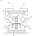
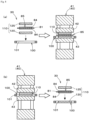
- JP 2018 200931 A In the transfer onto the resin layer of the thin plate-like laminate described above, as illustrated in, for example, FIG.
- a mold 210 having a mold surface 211 having a concave/convex surface shape is arranged on the resin layer 222 side with respect to a workpiece 220 having a substrate 221 on which a resin layer 222 is laminated and the workpiece is pressed via the mold 210, whereby a concave/convex shape 223 is formed on the resin layer 222.
- reference sign 200 represents compression means such as a pressing device
- reference sign 201 represents a machine base of the compression means 200.
- JP 2015 167152 A discloses a method as specified in the preamble of claim 1.
- This method adopts an imprint apparatus comprising means for affixing sheets of a thermoplastic material to both sides of a glass sheet, first and second molds in the form of an endless belt, a heater for softening the sheets of the thermoplastic material, and two pairs of rollers.
- the structure in which the molds are arranged between the two pairs of rollers can be considered a "mold retention structure".
- KR 2011 0127406 A and US 2016/361846 A1 disclose a method for the production of a component in which a conveyor introduces molds arranged on both surface sides of a workpiece between compression members.
- the present invention is proposed in light of the above circumstances, and provides a method for the production of a thin plate-like laminate having a film-like resin layer in which a concave/convex shape can stably be formed with high accuracy on the film-like resin layer laminated on a thin plate-like substrate.
- the method for the production of a thin plate-like laminate having a film-like resin layer has the features specified in claim 1.
- the step of creating the mold retention structure comprises a setting step wherein a mold retention structure in which the molds are arranged on both surface sides of the workpiece is created, and a heating step wherein entireties of the molds, after creation of the mold retention structure, are heated to the thermal deformation temperature of the film-like resin composition, which is economically advantageous because excessive heating of the molds is not necessary.
- the step of creating the mold retention structure comprises a heating step wherein the molds are heated to the thermal deformation temperature of the film-like resin composition, and a setting step wherein a mold retention structure in which the molds, which were heated in the heating step, are arranged on both side surfaces of the workpiece, is created, it is possible to heat to a high temperature in a short time, whereby operation time can be shortened, and oxidation of the film-like resin composition of the workpiece due to heating is suppressed, which enables high-quality molding.
- the substrate is a thin plate-like material having a thickness of 1 mm or less and the thickness of the film-like resin composition is 500 ⁇ m or less, lightweight and precise products can be obtained.
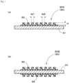
- the present invention relates to a method for the production of the thin plate-like laminate (80) having a film-like resin layer on which a predetermined concave/convex surface shape is formed on a surface thereof shown in FIG. 1 .
- the thin plate-like laminate 80 is a laminate in which a film-like resin layer 82 is laminated on at least one surface of a thin plate-like substrate 81, and the film-like resin layer 82 has a predetermined concave/convex shape 83.
- FIG. 1(a) shows a thin plate-like laminate 80A in which the film-like resin layer 82 is formed on one surface of the thin plate-like substrate 81, and FIG.
- FIG. 1(b) shows a thin plate-like laminate 80B in which the film-like rein layer 82 is formed on both surface sides of the thin plate-like substrate 81.
- the thin plate-like laminate 80 by forming the predetermined concave/convex shape 83 on the surface thereof, various products such as semiconductor substrates, optical members such as optical lenses and optical films, separators for fuel cells, wearable electrodes, sensors, electrostatic adsorbents, resistance heating elements, electromagnetic wave shield materials, connectors, solar cell members, and separators for water electrolysis devices can be produced.
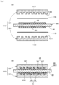
- the thin plate-like laminate 80 as shown in FIG. 2 , can be obtained by forming the predetermined concave/convex shape 83 on a surface of a film-like resin composition 84 laminated on at least one surface of the thin plate-like substrate 81 of a workpiece 85 by a predetermined mold 110.
- the thickness of the thin plate-like substrate 81 is 1 mm or less and the thickness of the film-like resin composition 84 is 500 ⁇ m or less, and more preferably, the thickness of the thin plate-like substrate 81 is 100 ⁇ m or less and the thickness of the film-like resin composition 84 is 50 to 150 ⁇ m.
- the thicknesses of the thin plate-like substrate 81 and the film-like resin composition 84 as described above, lightweight and precise products can be obtained. In particular, when imparting a conductive function, which is described later, suitable conductivity can be provided.
- the thin plate-like substrate 81 is a thin plate member composed of a material having corrosion resistance and heat resistance such as titanium, aluminum, and stainless steel (SUS).
- the film-like resin composition 84 is laminated on one or both sides of the thin plate-like substrate 81, a predetermined concave/convex shape 83 is formed on the surface thereof, and is constituted as a film-like resin layer 82.
- a predetermined concave/convex shape 83 is formed on the surface thereof, and is constituted as a film-like resin layer 82.
- the shape, size, etc., of the concave/convex shape 83 of the film-like resin layer 82 are determined in accordance with the application of the thin plate-like laminate 80 or the like, fine protrusions and concavities may be formed thereon.
- Examples of the material constituting the film-like resin composition 84 include ethylene homopolymers, propylene homopolymers (homopolypropylene), random copolymers of ethylene and one or two or more ⁇ -olefins such as propylene, 1-butene, 1-pentene, 1-hexene, 4-methyl-1-pentene, and block copolymers of the above components. Additionally, the examples of the material may include polyolefin resins such as the mixtures of the polymers described above, polyolefin elastomers, acid-modified polypropylene, acid-modified polyethylene, ethylene/vinyl alcohol copolymer resins, and hydrocarbon resins. Additional examples include fluororesins and fluororubbers. Furthermore, at least one type of conductive material such as a carbon material or a conductive ceramic may be added to these materials. Examples of the carbon material include carbon nanotubes, granular graphite, and carbon fibers.
- the film-like resin composition 84 is constituted as a decorative, adhesive, or conductive functional resin composition depending on the desired product to be produced.
- Decorative functional resin compositions are resin layers in which fine protrusions and concavities are subjected to surface treatment such as wrinkling (wrinkle pattern), embossing (embossed pattern), or reflective processing (matte tone).
- Adhesive functional resin compositions are resin layers having high adhesive strength composed of a polyethylene resin.
- Conductive functional resin compositions are energizable resin layers in which a carbon material is added to the resin material.
- the mold 110 is a member which is arranged on both surface sides of the substrate 81 of the workpiece 85 and which holds the workpiece 85, and comprises a lower mold 120 on which the workpiece 85 is placed and an upper mold 125 which is arranged above the workpiece 85.
- predetermined concave/convex surface shapes 122, 127 are formed in the mold surfaces 121, 126 of one or both of the lower mold 120 and the upper mold 125.
- the concave/convex surface shapes 122, 127 are formed on the mold surfaces 121, 126.
- concave/convex surface shape 122 (127) of the mold surface 121 (126) By imparting the concave/convex surface shape 122 (127) of the mold surface 121 (126) with a particularly fine concave/convex surface shape, a fine concave/convex shape can be stably formed with high accuracy on the film-like resin layer.
- the concave/convex surface shapes 122, 127 of the lower mold 120 and the upper mold 125 may be the same or may be different.
- interleaving paper (release paper) 115 for facilitating release of the molded workpiece (thin plate-like laminate 80) may be interposed between the mold surfaces 121, 126 of the mold 110 and the workpiece 85 as needed. Note that in FIG. 2(b) , interleaving paper has been omitted.
- the method for the production of a thin plate-like laminate of the present invention comprises a mold retention structure creation step, a compression step, and an extraction step, and if necessary, a cooling step is performed.
- the method for the production of a thin plate-like laminate can be carried out using, for example, the device 10 for the production of a thin plate-like laminate shown in FIG. 3 .
- the device 10 for the production of a thin plate-like laminate comprises a setting part 30 having a setting device 31, a heating part 40 having a heating device 41, a pressurization part 50 having a compression roller device 51, and an extraction part 60 having an extraction device 61.
- the method for the production of a thin plate-like laminate of the present invention will be described below along with the device 10 for the production of a thin plate-like laminate.
- the illustrated production device 10 comprises a machine base 11 which connects the setting part 30, the heating part 40, the pressurization part 50, and the extraction part 60 by means of a rail part 20.
- the rail part 20 has a rail body 21 composed of a pair of rod-shaped members located between the setting part 30, the heating part 40, the pressurization part 50, and the extraction part 60, and connects the setting part 30, the heating part 40, the pressurization part 50, and the extraction part 60 in series.
- the rail body 21 is installed so as to be capable of moving the mold 110 between the setting part 30, the heating part 40, the pressurization part 50, and the extraction part 60 by means of the mold retention structure 100.
- Reference sign 12 in the drawing indicates legs of the machine base 11 which support the rail part 20.
- the mold retention structure 100 is not particularly limited as long as it is capable of moving the mold 110 between the parts 30, 40, 50, and 60 while holding the workpiece 85.
- an appropriate structure such as a structure having clip members or the like for holding the lower mold 120 and the upper mold 125 can be adopted.
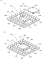
- the mold retention structure 100 shown in FIG. 4 is an example of a frame-like structure which retains the mold 110 in which the workpiece 85 is held, and moves between the setting part 30, the heating part 40, the pressurization part 50, and the extraction part 60 along the rail body 21.
- the mold retention structure 100 comprises a retention body 101 which has a lower opening 104, which is placed on the rail body 21, and which is capable of sliding, and a pair of mold retention parts 105, 105 which retain the lower mold 120 of the mold 110.
- mating protrusions 123 are provided at a plurality of positions of the lower mold 120, and a plurality of mating holes 128 corresponding to the mating protrusions 123 of the lower mold 120 are provided on the upper mold 125, and by mating the mating protrusions 123 of the lower mold 120 with corresponding mating holes 128 of the upper mold 125, the upper mold 125 is overlaid on the lower mold 120 at an appropriate position.
- FIG. 5 is a schematic plan view showing variations of the mold retention structure 100 and the mold 110.
- FIG. 5(a) is an example of a mold retention structure 100A in which a mold 110A for processing a single workpiece 85 is retained.
- the mold retention structure 100A comprises a frame-shaped retention body 101A composed of a pair of side edges 102, 102 which are slidably placed on the rail body 21 and edge parts 103, 103 that extend between both ends of the side edges 102, 102, and a pair of mold retention parts 105A, 105A extending between the edge parts 103, 103, and the mold 110A (lower mold 120) is affixed between the mold retention parts 105A, 105A by means of fixation members (not illustrated) such as screw members.
- fixation members not illustrated
- FIG. 5(b) is an example of a mold retention structure 100B in which a mold 110B for processing of a plurality of workpieces 85 are retained by the same mold surface.
- the 110B which is a rectangular mold in a plan view, is arranged between the edge parts 103, 103 of the retention body 101A, and the edge parts 103, 103 are affixed by affixation members (not illustrated) such as screw members as mold retention parts 105, 105.
- FIG. 5(c) is an example of a mold retention structure 100C in which a mold 110C for processing a comparatively-large workpiece 85 is retained.
- the mold 110C corresponding to the size of the entirety of the lower opening 104 is arranged in the lower opening 104 of the retention body 101A, and the side edges 102, 102 and the edge parts 103, 103 of the retention body 101A are affixed by means of affixation members (not illustrated) such as screw members as mold retention parts 105, 105, 105, 105.
- the frame-like structure of the mold retention structure is not limited to only the structures 100A to 100C described above, and an appropriate structure can be adopted in accordance with the number and size of workpieces 85, the shape of the mold, etc.
- a movement device which is capable of moving on the rail body 21 may be separately prepared, and a mold retention structure may be installed on the movement device to enable movement.
- the setting part 30 comprises a setting device 31 which creates the mold retention structure 100 in which the mold 110 is set.
- a known transport means such as a robot arm by which the retention body 101, the mold 110, and the workpiece 85 can be appropriately installed can suitably be used.
- transportation of the retention body 101, the mold 110, and the workpiece 85 between a work table and the rail part 20 is performed, and creation of the mold retention structure 100 is performed.
- the heating part 40 comprises a heating device 41 which heats the mold 110 to the thermal deformation temperature of the film-like resin composition 84.
- the heating device 41 is not particularly limited as long as it is capable of efficiently heating the mold 110.
- the heating device 41 of the Examples comprises hot plates 42, 43 which are capable of being raised and lowered and which are arranged above and below the rail body 21, and the heating device 41 is configured so as to hold and heat the mold 110 by means of the upper hot plate 42 and the lower hot plate 43.
- the heating of the mold 110 by the heating device 41 may be performed on the mold 110 in a state in which the workpiece 85 is held thereby, or may be performed on the mold 110 in a state in which the workpiece 85 is not held thereby.
- the mold 110, which holds the workpiece 85 is heated, excessive heating of the mold 110 is unnecessary, which is economically advantageous.
- heating the mold 110, which is not holding the workpiece 85 since only the mold 110 is heated, it can be heated to a high temperature in a short time to shorten the operation time, and oxidation of the film-like resin composition 84 of the workpiece 85 due to the heating is suppressed, which enables high-quality molding.
- the pressurization part 50 comprises a compression roller device 51 which compresses the outer surfaces of the heated mold 110 to form the thin plate-like laminate 80.
- the compression roller device 51 comprises a lower compression roller 52 which is arranged so as to be capable of rotating in a position in which it abuts the lower surface side of the mold 111, an upper compression roller 54 which is arranged in a position directly above the lower compression roller 52 and so as to be capable of rotating on the upper side of the mold retention structure 100, and a pressurization part lifting means 56 comprising a pressure cylinder or the like which raises and lowers the upper compression roller 54.
- the compression roller device 51 comprises a temperature adjusting means for adjusting the temperature of one or both of the lower compression roller 52 and the upper compression roller 54.
- reference sign 53 represents a lower rotational drive device which rotationally-drives the lower compression roller 52
- reference sign 55 represents an upper rotational drive device which rotationally-drives the upper compression roller 54
- reference sign 57 represents a rod part of the pressurization part lifting means 56.
- the mold retention structure 100 after heating of the mold 110, is introduced between the two compression rollers, and the outer surfaces of the mold 110 are compressed by rotating the compression rollers to integrally thermocompression-bond the film-like resin composition 84 and the substrate 81 to form the thin plate-like laminate 80 having the film-like resin layer 82.
- the compression roller device 51 of the Examples has a drive control device (not illustrated) which controls the rotation of the lower compression roller 52 and the upper compression roller 54, and when the mold 111 is compressed, the rotation of the two compression rollers 52, 54 and the shaking of the mold retention structure 100 are controlled so as to be synchronized.
- the extraction part 60 comprises an extraction device 61 which extracts the mold 110 or workpiece 85 from the mold retention structure 100 after compression.
- a known transport means such as a robot arm is suitably used, and the extraction device 61 transports the mold retention structure 100, the mold 110, or the workpiece 85 between the work table on which the mold, etc., after processing are placed and the rail part 20, and extracts the mold 110 or workpiece 85 from the mold retention structure 100.
- a cooling part 70 may be arranged on the machine base 11.
- the cooling part 70 comprises a cooling device 71 which cools the mold 110 compressed by the compression roller device 51.
- the cooling device 71 is not particularly limited as long as it is capable of cooling the thin plate-like laminate 80 via the mold 110.
- the cooling device 71 shown in FIG. 1 comprises cooling plates 72, 73 which are capable of being raised and lowered and which are arranged above and below the rail body 21, and the cooling device 71 is configured so as to hold and cool the mold 110 retained in the mold retention structure 100 by means of the upper cooling plate 72 and the lower cooling plate 73.
- the mold retention structure creation step is a step of creating a mold retention structure in which the molds 110 heated to the thermal deformation temperature of the film-like resin composition 84 are arranged on both sides of the workpiece 85.
- This mold retention structure creation step is configured such that as shown in, for example, FIG. 8(a) , the heating step is performed in the heating part 40 after the setting step performed in the setting part 30.
- the setting step shown in FIG. 8(a) is a step in which, in the setting part 30, using the setting device 31 (illustration omitted), the mold retention structure 100 in which the molds 110 are arranged on both surface sides of the workpiece 85 is created (setting step prior to heating).
- processes such as transporting the mold retention structure 100 onto the rail body 21 of the rail part 20 by the setting device 31, such as a robot arm, transporting the lower mold 120 and the upper mold 125 of mold 110 to the mold retention structure 100 and retaining them therein, and transporting the workpiece 85 to the mold are performed.
- the lower mold 120 of the mold 110 is retained in advance in the retention body 101 of the mold retention structure 100, and after the workpiece 85 is placed on the lower mold 120, the mold retention structure 100 retaining the lower mold 120 is transported onto the rail body 21, and thereafter setting processing in which the upper mold 125 is overlaid on the lower mold 120 is performed.
- the heating step shown in FIG. 8(a) is a step in which, in the heating part 40, using the heating device 41, the entirety of the mold 110 after creation of the mold retention structure 100 is heated to the thermal deformation temperature of the film-like resin composition 84 (heating step after setting).
- the heating step a process in which the lower mold 120 and the upper mold 125 of the mold 110 are heated by the heating device 41, and the workpiece 85 held in the mold 110 is heated to the thermal deformation temperature is performed on the mold retention structure 100, which has moved from the setting part 30 to the heating part 40.
- suitable processing of the workpiece 85 is enabled.
- the heating temperature is determined in accordance with the material of the film-like resin composition of the workpiece.
- the mold retention structure creation step may be configured such that the setting step is performed in the setting part 30 after the heating step performed in the heating part 40, as shown in FIG. 8(b) , instead of performing the heating step after the setting step.
- the heating step shown in FIG. 8(b) is a step (heating step prior to setting) in which, in the heating part 40, using the heating device 41, the mold is heated to the thermal deformation temperature of the film-like resin composition 84.
- this heating step a process in which the lower mold 120 and the upper mold 125 of the mold 110 are heated by the heating device 41 is performed on the molds 110 which are retained in the retention body 101 and which do not hold the workpiece 85.
- the mold 110 can be heated to a high temperature in a short time, and oxidation of the film-like resin composition 84 of the workpiece 85 by the heating is suppressed, which enables high-quality molding.
- the setting step shown in FIG. 8(b) is a step (setting step after heating) in which, in the setting part 30 using the setting device 31 (illustration omitted), the workpiece 85 is held in the heated mold 110, and the mold retention structure 100 is created.
- this setting step a setting process in which after the upper mold 125 of the mold 110 retained in the retention body 101 is temporarily removed by the setting device 31, such as a robot arm, the workpiece 85 is placed on the lower mold 120, and then the upper mold 125 is overlaid on the lower mold 120 is performed.
- the mold retention structure creation step in which the workpiece 85 is held in the mold 110 and the mold retention structure 100 is set after the mold 110 is heated, since only the mold 110 is heated, it can be heated to a high temperature in a short time, which reduced operation time, and oxidation of the film-like resin composition 84 of the workpiece 85 by the heating is suppressed, which enables high-quality molding.
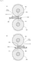
- the compression step is a step in which, in the pressurization part 50 as shown in FIGS. 6 , 7 , 9 , and 10 , the mold retention structure 100, in which the heated mold 110 is arranged, is introduced between the two compression rollers 52, 54 of the compression roller device 51 and the outer surfaces of the mold 111 are compressed by rotating the compression rollers 52, 54 to integrally thermocompression-bond the film-like resin composition and the substrate to form the thin plate-like laminate 80 having the film-like resin layer 82.
- the compression step a process in which the entirety of the workpiece 85 held in the mold 111 is roll-pressed while shaking the mold retention structure 100 is performed on the heated mold 111 of the mold retention structure 100, which has moved from setting part 30 or the heating part 40 to the pressurization part 50.
- the upper compression roller 54 contacts (P2) and presses the mold 111 at a position directly above the contact position P1 between the lower compression roller 52 and the mold 111.
- the mold 111 is subjected to the compression force from the two compression rollers 52, 54 between the contact position P1 with the lower compression roller 52 and the contact position P2 with the upper compression roller 54.
- a pressing force acts on the mold 210 in a two-dimensional (planar) manner.
- the pressurizing means 200 such as a pressing device
- a pressing force acts on the mold 210 in a two-dimensional (planar) manner.
- the pressure is dispersed so as to act on the entirety of the mold 210, and the pressing force does not always act uniformly on the entire mold 210, which may cause pressure unevenness.
- a one-dimensional (linear) pressing force between the contact positions P1 and P2 acts on the mold 111 retained by the mold retention structure 100.
- the pressure acts two-dimensionally (planar)
- the pressure is concentrated and it becomes easier to apply a large pressing force, and moreover, since the pressurized part of the mold 111 is limited to the portion between the contact positions P1 and P2, the pressurization acts relatively uniformly and the occurrence of pressure unevenness is suppressed.
- the mold retention structure 100 is shaken so that the pressurized portion (between the contact positions P1, P2) of the mold 111 acts at least on the entirety of the workpiece 85 (between positions 86, 86 of the ends of the workpiece 85), which is held in the mold 111 of the mold retention structure 100.
- the two compression rollers 52, 54 rotate in the same direction (for example, in FIG.
- the lower compression roller 52 rotates in the counterclockwise direction and the upper compression roller 54 rotates in the clockwise direction) in a compressing state
- the two compression rollers 52, 54 rotate in the same direction (for example, in FIG. 10(b) , the lower compression roller 52 rotates in the clockwise direction and the upper compression roller 54 rotates in the counterclockwise direction) in a compressing state.
- the shaking of the mold retention structure 100 and the rotational driving of the compression rollers 52, 54 are controlled so as to be performed synchronously by the drive controller (not illustrated) of the pressurization part 50.
- the movement timing (shaking timing) of the mold retention structure 100, the rotational timing of the compression rollers 52, 54, the movement direction (shaking direction) of the mold retention structure 100, the rotational directions of the compression rollers 52, 54, the movement distance (shaking range) of the mold retention structure 100, and the rotation amounts of the compression rollers 52, 54 are controlled so as to match.
- smooth movement of the mold retention structure 100 is enabled in a state in which the predetermined pressure applied on the mold 111 from the two compression rollers 52, 54 is retained.
- the compression position (between P1 and P2) by the two compression rollers 52, 54 extends over the entire surface of the mold 111, whereby the entire surface of the mold 111 can be substantially-uniformly pressurized.
- the shaking of the mold retention structure 100 is performed as many times as necessary, including once (one round trip), depending on the type of the resin layer, the fineness of the concave/convex shape, the target product, etc.
- the start position and end position of the compression by the two compression rollers 52, 54 are appropriately determined in accordance with the size of the workpiece 85, the type of the concave/convex shape, etc.
- the temperature of one or both of the lower compression roller 52 and the upper compression roller 54 may be adjusted by the temperature adjusting means (not illustrated) during the compression by the compression roller device 51.
- the temperature adjustment by the temperature adjusting means may be any appropriate method such as heating, cooling, and heat retention.
- the temperature of the mold 110 may change during compression, whereby it may be difficult to perform appropriate processing.
- the temperature of the mold 110 at the time of compression is appropriately maintained by heating or maintaining the temperature when the temperature of the mold 110 is low, or by cooling when the temperature is excessively high.
- the extraction step is a step in which, in the extraction part 60, using the extraction device 61, the mold 110 after compression is extracted from the mold retention structure 100.
- the extraction step a process in which the mold retention structure 100 is transported from the rail body 21 of the rail part 20 by the extraction device 61, such as a robot arm, the lower mold 120 and the upper mold 125 of the mold 110 are extracted from the mold retention structure 100, and the workpiece 85 is extracted from the mold 110 is performed on the mold retention structure 100, which has moved from the pressurization part 50 to the extraction part 60.
- the mold retention structure 100 in which the lower mold 120 is retained is transported from the rail body 21 to another placement position, such as a work table, and the thin plate-like laminate 80 (processed workpiece) placed on the lower mold 120 is extracted.
- the production method is completed.
- the thin plate-like laminate 80 immediately after processing is in a state in which it can be easily deformed by the heating of the heating part 40.
- the thin plate-like laminate 80 is cooled to a temperature at which inadvertent deformation does not occur.
- slow-cooling such as allowing the thin plate-like laminate 80 to stand for a predetermined time without extracting it from the mold 110, but it is preferable that the device 10 for the production of a thin plate-like laminate be provided with a cooling part 70 to perform the cooling step.
- the cooling step is a step in which, in the cooling part 70, using the cooling device 71, the entirety of the mold 110 after compression retained in the mold retention structure 100 is cooled.
- a process in which the lower mold 120 and the upper mold 125 of the mold 110 are cooled by the cooling device 71, and the processed thin plate-like laminate 80 held in the mold 110 is cooled to a temperature at which inadvertent deformation does not occur is performed on the mold retention structure 100, which has moved from the pressurization part 50 to the cooling part 70.
- the shape of the concave/convex surface of the thin plate-like laminate 80 is stabilized, and the molding of the thin plate-like laminate 80 in the mold 110 is complete.
- the mold retention structure 100 is moved from the cooling part 70 to the extraction part 60 and the extraction step described above is performed.
- the cooling temperature is lower than the thermal deformation temperature of the film-like resin composition 84 by 20 °C or more.
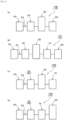
- FIG. 11 shows variations (10A to 10D) of the device for the production of a thin plate-like laminate in which after the workpiece is held by the molds in the setting part 30 and the mold retention structure is created, the molds holding the workpiece are heated in the heating part 40.
- FIG. 12 shows variations (10E to 10H) of the device for the production of a thin plate-like laminate in which after the molds which are not holding the workpiece are heated in the heating part 40, the workpiece is held in molds in the setting part 30 and the mold retention structure is created.
- the device 10A for the production of a thin plate-like laminate shown in FIG. 11(a) is an example in which the setting part 30, the heating part 40, the pressurization part 50, and the extraction part 60 are arranged in series on the rail part 20.
- the workpiece is transported from the downstream side of the rail part 20 (setting part 30 side) and processed, and the processed thin plate-like laminate is transported to the upstream side of the rail part 20 (extraction part 60 side).
- the device 10A can be incorporated into the line process of a production line of various products using the thin plate-like laminates, and the thin plate-like laminates extracted by the extraction part 60 can be continuously transferred to another processing process.
- the device 10B for the production of a thin plate-like laminate shown in FIG. 11(b) is an example in which the cooling part 70 is provided between the pressurization part 50 and the extraction part 60, and the setting part 30, the heating part 40, the pressurization part 50, the cooling part 70, and the extraction part 60 are arranged in series in this order on the rail part 20.
- the shape of the concave/convex surface of the thin plate-like laminate can be stabilized by the cooling part 70, and the device 10B for the production of a thin plate-like laminate can be incorporated into the line process of a production line in the same manner as the production device 10A.
- the device 10C for the production of a thin plate-like laminate shown in FIG. 11(c) is an example in which the setting part 30 and the extraction part 60 are shared, and the setting device 31 and the extraction device 61 are shared, and the setting part 30, which also serves as the extraction part 60, the heating part 40, the pressurization part 50, and the cooling part 70 are arranged in series on the rail part 20 in this order.
- the setting part 30 and the extraction part 60 are configured so as to be shared, the space for the production device 10C can be reduced, and equipment to be used can be omitted to reduce cost.
- the workpiece transported from the setting part 30 is processed by the pressurization part 50 and then returned to the setting part 30 (which also serves as the extraction part 60) and extracted, man-hours during batch work can be reduced and work efficiency can be improved.
- the device 10D for the production of a thin plate-like laminate shown in FIG. 11(d) is an example in which the setting part 30 and the extraction part 60 are shared, and the setting device 31 and the extraction device 61 are shared, and the setting part 30, which also serves as the extraction part 60, the cooling part 70, the heating part 40, and the pressurization part 50 are arranged in series on the rail part 20 in this order.
- the pressurization part 50 is arranged on the outermost side of the production device 10D, maintenance operations such as preparation of the compression roller device of the pressurization part 50 becomes easy.
- space can be reduced to reduce cost, and work efficiency can be improved during batch work.
- the device 10E for the production of a thin plate-like laminate shown in FIG. 12(a) is an example in which the heating part 40, the setting part 30, the pressurization part 50, and the extraction part 60 are arranged in series on the rail part 20 in this order.
- the device 10E for the production of a thin plate-like laminate is configured such that the setting part 30 and the heating part 40 are reversed as compared to the device 10A for the production of a thin plate-like laminate.
- the workpiece is processed while being transported from the downstream side (the heating part 40 side) of the rail part 20 to the upstream side (the extraction part 60 side). Therefore, the device 10E for the production of a thin plate-like laminate can be incorporated into the line process of a production line of various products in the same manner as the production device 10A, and the produced thin plate-like laminates can be continuously transferred to another processing process.
- the device 10F for the production of a thin plate-like laminate shown in FIG. 12(b) is configured such that the setting part 30 and the heating part 40 are reversed as compared to the device 10B for the production of a thin plate-like laminate, and is an example in which the heating part 40, the setting part 30, the pressurization part 50, the cooling part 70, and the extraction part 60 are arranged in series on the rail part 20 in this order.
- the shape of the concave/convex surface of the thin plate-like laminate can be stabilized by the cooling part 70, and the device 10F for the production of a thin plate-like laminate can be incorporated into the line process of a production line.
- the device 10G for the production of a thin plate-like laminate shown in FIG. 12(c) is configured such that the setting part 30 and the heating part 40 are reversed as compared to the device 10C for the production of a thin plate-like laminate, and is an example in which the heating part 40, the setting part 30, which serves as the extraction part 60, the pressurization part 50, and the cooling part 70, are arranged in series on the rail part 20 in this order.
- the space for the production device 10G in the same manner as the device 10C for the production of a thin plate-like laminate, the space for the production device 10G can be reduced, equipment to be used can be omitted to reduce the cost, man-hours during batch work can be reduced, and work efficiency can be improved.
- the device 10H for the production of a thin plate-like laminate shown in FIG. 12(d) is an example in which the heating part 40, the setting part 30, which serves as the extraction part 60, the cooling part 70, and the pressurization part 50 are arranged in series on the rail part 20 in this order.
- maintenance operations such as preparation of the compression roller device of pressurization part 50 becomes easy.
- space can be reduced to reduce cost, and work efficiency can be improved during batch work.
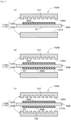
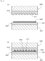
- FIG. 13(a) is an example of a mold structure 150A in which a mold 112A for single-side processing is arranged relative to a workpiece 85A in which a film-like resin composition 84A is laminated on one surface side (the upper surface side in the example of the drawing) of the substrate 81.
- the mold 112A comprises a lower mold 120A having a mold surface 121A, which is a smooth surface, and an upper mold 125A having a mold surface 126A on which the concave/convex surface shape 127 is formed.
- the smooth lower mold 120A contacts the second side (the lower surface side) of the substrate 81 of the workpiece 85A
- the upper mold 125A on which the concave/convex surface shape 127 is formed contacts the resin composition 84A on the first side (upper surface side) of the substrate 81, whereby the concave/convex shape can be formed on only the resin composition 84A on the first surface side (upper surface side) of the substrate 81.
- FIG. 13(b) is an example of a mold structure 150B in which a mold 112A for single-side processing is arranged relative to a workpiece 85B in which film-like resin compositions 84A, 84B are laminated on both surfaces of the substrate 81.
- the smooth lower mold 120A contacts the resin composition 84B on the second side (lower surface side) of the substrate 81 of the workpiece 85A
- the upper mold 125A on which the concave/convex surface shape 127 is formed contacts the resin composition 84A on the first side (upper surface side) of the substrate 81.
- the resin composition 84B on the second side (lower surface side) of the substrate 81 is formed into a smooth resin layer by the lower mold 120A, and a concave/convex shape can be formed on only the resin composition 84A on the first side (upper surface side).
- FIG. 13(c) is an example of a mold structure 150C in which a mold 112B for double-sided processing is arranged relative to a workpiece 85B in which film-like resin compositions 84A, 84B are laminated on both surfaces of the substrate 81.
- the mold 112B comprises a lower mold 120B having a mold surface 121B on which the concave/convex surface shape 122 is formed, and an upper mold 125A having a mold surface 126A on which the concave/convex surface shape 127 is formed.
- the lower mold 120B on which the concave/convex surface shape 122 is formed contacts the resin composition 84B on the second side (lower surface side) of the substrate 81
- the upper mold 125A on which the concave/convex surface shape 127 is formed contacts the resin composition 84A on the first side (upper surface side) of the substrate 81.
- concave/convex shapes can be formed on the resin compositions 84B, 84A on the surfaces of the substrate 81 by the lower mold 120B and the upper mold 125A.
- a single resin layer having a concave/convex shape can be appropriately formed on the substrate 81.
- the mold structures 150B, 150C shown in FIGS. 13(b) and 13(c) are examples of processing of a workpiece 85B in which the film-like resin compositions 84A, 84B are laminated on both surfaces of the substrate 81.
- a resin layer having a concave/convex shape and having a predetermined functionality can be formed on one side of the substrate 81, and a resin layer such as a smooth adhesive layer can be formed on the other side.
- resin layers having concave/convex shapes and predetermined functionalities can be formed on both surfaces of the substrate 81.
- the mold structure 150C by providing the lower mold 120B and the upper mold 125A with different concave/convex shapes, concave/convex shapes having different patterns can be formed on the surfaces of the substrate 81.
- the resin compositions 84A, 84B By laminating the resin compositions 84A, 84B on the surfaces of the substrate 81 in this manner, products with various functionalities can easily be produced.
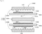
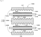
- FIGS. 14 and 15 are examples of mold structures 150D, 150E in which processing is performed simultaneously on a plurality (two in the examples of the drawings) of workpieces.
- a mold 112C which is capable of processing a plurality of workpieces is arranged relative to a workpiece 85C in which the film-like resin composition 84A is laminated on one surface side (the upper surface side in the example of the drawing) of the substrate 81 and another workpiece 85D in which film-like resin compositions 84A, 84B are laminated on both surfaces of the substrate 81.
- the mold 112C comprises a lower mold 120B having a mold surface 121B on which the concave/convex surface shape 122 is formed, an upper mold 125A having a mold surface 126A on which the concave/convex surface shape 127 is formed, and a middle mold 130A having smooth mold surfaces 131A, 136A on both surfaces thereof.
- the lower mold 120B on which the concave/convex surface shape 122 is formed contacts the resin composition 84B on the second side (lower surface side) of the substrate 81 of the second workpiece 85D
- the upper mold 125A on which the concave/convex surface shape 127 is formed contacts the resin composition 84A on the first side (upper surface side) of the substrate 81 of the first workpiece 85C
- the middle mold 130A is interposed between the first workpiece 85C and the second workpiece 85D
- the smooth upper mold surface 131A of the middle mold 130A contacts the second side (lower surface side) of the substrate 81 of the first workpiece 85C
- the smooth lower mold surface 136A of the middle mold 130A contacts the resin composition 84A on the first side (upper surface side) of the substrate 81 of the second workpiece 85D.
- the concave/convex shape is formed on only the resin composition 84A on the first side (upper surface side) of the one workpiece 85C by the upper mold 125A, and on the second workpiece 85D, the concave/convex shape is formed on only the resin composition 84B on the second side (lower surface side) of the substrate 81 by the lower mold 120A, and the resin composition 84A on the first side (upper surface side) can be formed as a smooth resin layer.
- a mold 112D which is capable of processing a plurality of workpieces is arranged relative to a workpiece 85E in which the film-like resin compositions 84A, 84B are laminated on both surfaces of the substrate 81 and another workpiece 85F in which the film-like resin compositions 84A, 84B are likewise laminated on both surfaces of the substrate 81.
- the mold 112D comprise a lower mold 120B having a mold surface 121B on which the concave/convex surface shape 122 is formed, an upper mold 125Ahaving a mold surface 126A on which the concave/convex surface shape 127 is formed, and a middle mold 130B having mold surfaces 131B, 136B on which the concave/convex surface shapes 132, 137 are formed on both surfaces thereof.
- the lower mold 120B on which the concave/convex surface shape 122 is formed contacts the resin composition 84B on the second side (lower surface side) of the substrate 81 of the second workpiece 85F
- the upper mold 125A on which the concave/convex surface shape 127 is formed contacts the resin composition 84A on the first side (upper surface side) of the substrate 81 of the first workpiece 85E
- the middle mold 130B is interposed between the first workpiece 85E and the second workpiece 85F
- the upper mold surface 131B on which the upper concave/convex surface shape 132 of the middle mold 130B is formed contacts the second side (lower surface side) of the substrate 81 of the first workpiece 85E
- the lower mold surface 136B on which the lower concave/convex surface shape 137 of the middle mold 130B is formed contacts the resin composition 84A on the first side (upper surface side) of the substrate 81 of the second workpiece 85F.
- the concave/convex shape can be formed on the resin composition 84A on the first side (upper surface side) by the upper mold 125A, and the concave/convex shape can be formed on the resin composition 84B on the second side (lower surface side) by the upper mold surface 131B of the middle mold 130B, and on the second workpiece 85F, the concave/convex shape can be formed on the resin composition 84B on the other side (lower surface side) of the substrate 81 by the lower mold 120B and the concave/convex shape can be formed on the resin composition 84A on the first side (upper surface side) by the lower mold surface 136B of the middle mold 130B.
- a plurality of thin plate-like laminates having different types can be molded.
- a plurality of identical thin plate-like laminates can be molded.
- the middle molds 130A, 130B of the mold structures 150D, 150E are configured so as to have the same mold surface on both sides thereof, a plurality of different thin plate-like laminates can be molded by forming different mold surfaces, for example, one is a smooth mold surface and the other is a mold surface having a concave/convex shape.
- the number of workpieces to be simultaneously processed is not particularly limited, and is preferably approximately 2 to 3 from the viewpoint of processing accuracy, etc.
- the thin plate-like laminates of Prototype Examples 1 to 3 were produced under the following conditions using workpieces in which carbon-coated stainless steel (SUS316L) was used as the substrate, and a mixture of a polypropylene-based resin, carbon nanotubes (CNT), and graphite was used as the film-like resin composition.
- SUS316L carbon-coated stainless steel
- CNT carbon nanotubes
- the above workpiece was held in a mold and a mold retention structure was created (operation time: approximately 10 seconds), and after heating was performed in the heating part at a heating temperature of 200 °C for a heating time of 120 seconds, and thermocompression-bonding was performed in the pressurization part with compression rollers at a pressure of 40 kN, a pressurization time of 20 seconds, and a pressurization temperature of 200 °C, the workpiece was slowly cooled to obtain the thin plate-like laminate of Prototype Example 1.
- the above workpiece was held in a mold and a mold retention structure was created (operation time: approximately 10 seconds), and after heating was performed in the heating part at a heating temperature of 300 °C for a heating time of 30 seconds, and thermocompression-bonding was performed in the pressurization part with compression rollers at a pressure of 40 kN, a pressurization time of 20 seconds, and a pressurization temperature of 200 °C, the workpiece was slowly cooled to obtain the thin plate-like laminate of Prototype Example 2.
- heating was performed on the mold at a heating temperature of 300 °C for a heating time of 30 seconds, in the setting part, the above workpiece was held in the heated mold and the mold retention structure was created (operation time: approximately 10 seconds), and after thermocompression-bonding was performed in the pressurization part with compression rollers at a pressure of 40 kN, a pressurization time of 20 seconds, and a pressurization temperature of 200 °C, the workpiece was slowly cooled to obtain the thin plate-like laminate of Prototype Example 3.
- Prototype Example 1 the mold in which the workpiece was held was processed by gently heating it.
- Prototype Example 2 the mold in which the workpiece was held was heated at a higher temperature and in a shorter time than in Prototype Example 1 to perform processing.
- Prototype Example 3 the mold, which did not hold the workpiece, was heated at a higher temperature and in a shorter time than in Prototype Example 1, and immediately thereafter, the unheated workpiece was held by the heated mold and processing was performed.
- Table 1 the thin plate-like laminate of Prototype Example 2 was able to be molded with a quality that does not cause any problems as a product.
- the molded product was in an extremely suitable state as compared with Prototype Example 2.
- Prototype Example 2 As can be understood from the comparison of Prototype Example 1 and Prototype Example 2, it was found that when the mold in which the workpiece is held is heated, a higher-quality product can be obtained at a relatively low temperature and with gentle heating than with high-temperature and short time heating. This is because in Prototype Example 2, the workpiece is heated to a higher temperature, together with the mold, as compared with Prototype Example 1, and thus, the film-like resin composition of the workpiece is more easily oxidized than in Prototype Example 1, whereby it is considered that quality is less likely to be improved.
- Prototype Example 3 by heating the mold, which did not hold the workpiece, and then holding the workpiece therein, a high-quality product was obtained, as in Prototype Example 1. It is considered that this is because the workpiece was not exposed to a high temperature at the time of heating the mold in Prototype Example 3, and thus, the oxidation of the film-like resin composition of the workpiece was suppressed as compared with Prototype Example 2, which enabled high-quality molding. Furthermore, since in Prototype Example 3, the mold could be heated in a shorter time than in Prototype Example 1, operation time can be shortened as compared with Prototype Example 1.
- the method for the production of a thin plate-like laminate having a film-like resin layer of the present invention comprises the steps of creating a mold retention structure in which molds, which have been heated to a thermal deformation temperature of the thin film-like resin composition, are arranged on both surface sides of a workpiece, and introducing the mold retention structure in which the heated molds are arranged between two compression rollers and compressing the outer surfaces of the molds by rotating the compression rollers to integrally thermocompression-bond the film-like resin composition and the substrate to form a thin plate-like laminate having a film-like resin layer, pressure is applied uniformly to the molds to suppress the occurrence of pressure unevenness, and the concave/convex shape can be formed on the film-like resin layer laminated on the thin plate-like substrate with high accuracy and stability. In particular, a fine concave/convex shape can be accurately and stably formed one the film-like resin layer laminated on the thin plate-like substrate.
- the method for the production of a thin plate-like laminate having a film-like resin layer of the present invention is not limited to only the Examples described above, and a portion of the structure can be appropriately modified without departing from the spirit of the invention.
- the step of creating the mold retention structure in the setting part and the heating part though a step in which the mold is heated to the thermal deformation temperature of the film-like resin composition after the creation of the mold retention structure in which the mold in which the workpiece is held is arranged or a step in which the mold in which the workpiece is not held is heated to the thermal deformation temperature of the film-like resin composition, the workpiece is then held in the heated mold and the mold retention structure is created was adopted in the Examples described above, this step is not limited thereto.
- a step in which the mold retention structure is created after the mold, which is not retained in the retention body and in which the workpiece is held, is heated, a step in which the mold, which is not retained in the retention body and which does not hold the workpiece, is heated, and the workpiece is then held in the mold to create the mold creation structure, etc. can be performed by an appropriate procedure as long as it is a step in which the mold retention structure in which the heated mold in which the workpiece is held is arranged is ultimately created in the setting part and the heating part.
- the array combination of the setting part, the heating part, the pressurization part, and the extraction part of the device for the production of a thin plate-like laminate is not limited to only the Examples described above, but it can be appropriately configured in accordance with the application, the installation location, etc.
- the setting part, the heating part, the pressurization part, and the extraction part are connected in series by the rail part provided on the machine base of the device for the production of a thin plate-like laminate, and the mold retention structure is configured so as to be capable of moving on the rail part in the Examples described above, a rail part may not be provided and the mold retention structure may be moved by means of a known transfer device or the like.
- the method for the production of a thin plate-like laminate of the present invention can uniformly pressurize the molds to form a concave/convex shape stably in high accuracy on the film-like resin layer laminated on the thin plate-like substrate.
- it is a promising alternative to conventional thin plate-like laminate production methods.
Landscapes
- Engineering & Computer Science (AREA)
- Mechanical Engineering (AREA)
- Physics & Mathematics (AREA)
- Fluid Mechanics (AREA)
- Casting Or Compression Moulding Of Plastics Or The Like (AREA)
- Shaping Of Tube Ends By Bending Or Straightening (AREA)
Claims (9)
- Verfahren zur Herstellung eines dünnen plattenartigen Laminats (80) mit einer folienartigen Harzschicht (82), wobei auf beiden Oberflächenseiten eines Werkstücks (85), bei dem eine folienartige Harzzusammensetzung (84) auf mindestens einer Oberfläche eines Substrats (31) laminiert ist, Formen (120, 125) angeordnet werden und die Formen (120, 125) von Außenflächen der Formen (120, 125) aus zusammengedrückt werden, um das Substrat (81) und die folienartige Harzzusammensetzung (84) zu einer Einheit auszubilden, wobei das Verfahren die folgenden Schritte umfasst:Schaffen einer Formhaltestruktur (100), bei der die Formen (120, 125), die auf eine thermische Verformungstemperatur der folienartigen Harzzusammensetzung (84) erhitzt worden sind, auf beiden Oberflächenseiten des Werkstücks (85) angeordnet sind, undEinführen der Formhaltestruktur (100) zwischen zwei Druckwalzen (52, 54) und Zusammendrücken der Außenflächen der Formen (120, 125) durch Drehen der Druckwalzen (52, 54), um die folienartige Harzzusammensetzung (84) und das Substrat (81) durch Thermokompression zu einer Einheit zu verbinden, um ein dünnes plattenartiges Laminat (80) mit einer folienartigen Harzschicht (82) auszubilden,dadurch gekennzeichnet, dassdie Formhaltestruktur (100) Elemente zum Halten der Formen (120, 125) aufweist unddie Formhaltestruktur (100), in der die erhitzten Formen (120, 125) angeordnet sind, indem sie durch die Elemente zum Halten der Formen (120, 125) gehalten werden, zwischen den Druckwalzen (52, 54) eingeführt wird.
- Verfahren zur Herstellung eines dünnen plattenartigen Laminats (80) mit einer folienartigen Harzschicht (82) nach Anspruch 1, wobei der Schritt des Schaffens der Formhaltestruktur (100) Folgendes umfasst:einen Einrichtungsschritt, wobei eine Formhaltestruktur (100) geschaffen wird, bei der die Formen (120, 125) auf beiden Oberflächenseiten des Werkstücks (85) angeordnet sind, undeinen Heizschritt, wobei Gesamtheiten der Formen (120, 125) nach Schaffung der Formhaltestruktur (100) auf die thermische Verformungstemperatur der folienartigen Harzzusammensetzung (84) erhitzt werden.
- Verfahren zur Herstellung eines dünnen plattenartigen Laminats (80) mit einer folienartigen Harzschicht (82) nach Anspruch 1, wobei der Schritt des Schaffens der Formhaltestruktur (100) Folgendes umfasst:einen Heizschritt, wobei die Formen (120, 125) auf die thermische Verformungstemperatur der folienartigen Harzzusammensetzung (84) erhitzt werden, undeinen Einrichtungsschritt, wobei eine Formhaltestruktur (100) geschaffen wird, bei der die Formen (120, 125), die in dem Heizschritt erhitzt wurden, auf beiden Seiten Oberflächen des Werkstücks (85) angeordnet sind.
- Verfahren zur Herstellung eines dünnen plattenartigen Laminats (80) mit einer folienartigen Harzschicht (82) nach einem der Ansprüche 1 bis 3, das außerdem einen Kühlschritt umfasst, wobei die durch die Druckwalzen (52, 54) zusammengedrückten Formen (120, 125) gekühlt werden.
- Verfahren zur Herstellung eines dünnen plattenartigen Laminats (80) mit einer folienartigen Harzschicht (82) nach einem der Ansprüche 1 bis 4, wobei das Substrat (81) ein dünnes plattenartiges Material mit einer Dicke von 1 mm oder weniger ist und die Dicke der folienartigen Harzzusammensetzung (84) 500 µm oder weniger beträgt.
- Verfahren zur Herstellung eines dünnen plattenartigen Laminats (80) mit einer folienartigen Harzschicht (82) nach einem der Ansprüche 1 bis 5, wobei die folienartige Harzzusammensetzung (84) auf jeder Oberfläche des Substrats (81) laminiert ist.
- Verfahren zur Herstellung eines dünnen plattenartigen Laminats (80) mit einer folienartigen Harzschicht (82) nach einem der Ansprüche 1 bis 6, wobei eine Vielzahl der Werkstücke (85) angeordnet wird und die Formen (120, 125) auf beiden Oberflächenseiten von jedem der Werkstücke (85) angeordnet werden.
- Verfahren zur Herstellung eines dünnen plattenartigen Laminats (80) mit einer folienartigen Harzschicht (82) nach einem der Ansprüche 1 bis 7, wobei die folienartige Harzzusammensetzung (84) eine dekorative, klebende oder leitende funktionale Harzzusammensetzung ist.
- Verfahren zur Herstellung eines dünnen plattenartigen Laminats (80) mit einer folienartigen Harzschicht (82) nach einem der Ansprüche 1 bis 8, wobei Formoberflächen der Formen (120, 125) feine konkave/konvexe Oberflächenformen haben.
Applications Claiming Priority (3)
| Application Number | Priority Date | Filing Date | Title |
|---|---|---|---|
| JP2019056972 | 2019-03-25 | ||
| JP2020044240A JP7413097B2 (ja) | 2019-03-25 | 2020-03-13 | フィルム状樹脂層を有する薄板状積層物の製造方法 |
| PCT/JP2020/011963 WO2020196152A1 (ja) | 2019-03-25 | 2020-03-18 | フィルム状樹脂層を有する薄板状積層物の製造方法 |
Publications (3)
| Publication Number | Publication Date |
|---|---|
| EP3950331A1 EP3950331A1 (de) | 2022-02-09 |
| EP3950331A4 EP3950331A4 (de) | 2022-12-07 |
| EP3950331B1 true EP3950331B1 (de) | 2025-06-04 |
Family
ID=72610165
Family Applications (1)
| Application Number | Title | Priority Date | Filing Date |
|---|---|---|---|
| EP20776434.1A Active EP3950331B1 (de) | 2019-03-25 | 2020-03-18 | Verfahren zur herstellung eines dünnplattenförmigen laminats mit filmartiger harzschicht |
Country Status (6)
| Country | Link |
|---|---|
| US (1) | US11745488B2 (de) |
| EP (1) | EP3950331B1 (de) |
| KR (1) | KR20210146332A (de) |
| ES (1) | ES3036564T3 (de) |
| MX (1) | MX2021011268A (de) |
| WO (1) | WO2020196152A1 (de) |
Families Citing this family (2)
| Publication number | Priority date | Publication date | Assignee | Title |
|---|---|---|---|---|
| WO2020196151A1 (ja) * | 2019-03-25 | 2020-10-01 | フタムラ化学株式会社 | フィルム状樹脂層を有する薄板状積層物の製造装置 |
| CN117656412B (zh) * | 2024-01-31 | 2024-04-09 | 青州市汇源包装材料有限公司 | 四层共挤塑料薄膜挤出流延成型生产装置 |
Family Cites Families (7)
| Publication number | Priority date | Publication date | Assignee | Title |
|---|---|---|---|---|
| JPH10282315A (ja) * | 1997-04-10 | 1998-10-23 | Matsushita Electric Ind Co Ltd | 光拡散板およびその製造方法 |
| JP5065880B2 (ja) | 2007-12-27 | 2012-11-07 | 株式会社日立産機システム | 微細構造転写装置および微細構造転写方法 |
| KR20110127406A (ko) * | 2010-05-19 | 2011-11-25 | 일도에프엔씨(주) | 연료전지용 분리판 제조 시스템 |
| JP2015167152A (ja) * | 2012-07-10 | 2015-09-24 | 旭硝子株式会社 | インプリント方法、及びインプリント装置 |
| JP6063960B2 (ja) * | 2013-01-11 | 2017-01-18 | 富士フイルム株式会社 | 多層光情報記録ディスクの製造方法 |
| DE102013226753A1 (de) * | 2013-12-19 | 2015-06-25 | Airbus Operations Gmbh | Vorrichtung und Verfahren zur kontinuierlichen Fertigung von Strukturbauteilen aus faserverstärkten Verbundmaterialien sowie Formwerkzeugset |
| JP7039865B2 (ja) | 2017-05-26 | 2022-03-23 | 大日本印刷株式会社 | パターン形成方法、凹凸構造体の製造方法、レプリカモールドの製造方法、レジストパターン改質装置及びパターン形成システム |
-
2020
- 2020-03-18 US US17/440,731 patent/US11745488B2/en active Active
- 2020-03-18 EP EP20776434.1A patent/EP3950331B1/de active Active
- 2020-03-18 ES ES20776434T patent/ES3036564T3/es active Active
- 2020-03-18 KR KR1020217032704A patent/KR20210146332A/ko active Pending
- 2020-03-18 WO PCT/JP2020/011963 patent/WO2020196152A1/ja not_active Ceased
- 2020-03-18 MX MX2021011268A patent/MX2021011268A/es unknown
Also Published As
| Publication number | Publication date |
|---|---|
| EP3950331A1 (de) | 2022-02-09 |
| US11745488B2 (en) | 2023-09-05 |
| ES3036564T3 (en) | 2025-09-22 |
| MX2021011268A (es) | 2021-10-01 |
| US20220176686A1 (en) | 2022-06-09 |
| KR20210146332A (ko) | 2021-12-03 |
| WO2020196152A1 (ja) | 2020-10-01 |
| EP3950331A4 (de) | 2022-12-07 |
Similar Documents
| Publication | Publication Date | Title |
|---|---|---|
| EP3183221B1 (de) | Verfahren zur formung von geformten glasartikeln aus glasscheiben | |
| TWI331557B (en) | Laminate molding apparatus and laminate molding process | |
| US9511620B2 (en) | Hot stamping machine | |
| CN106505212B (zh) | 用于燃料电池的膜电极组件的热处理设备 | |
| JP5586995B2 (ja) | 転写装置及び転写方法 | |
| EP3950331B1 (de) | Verfahren zur herstellung eines dünnplattenförmigen laminats mit filmartiger harzschicht | |
| CN107921812B (zh) | 用于转印压印膜的装饰区段的方法和装置 | |
| JP3803820B2 (ja) | 積層成形装置 | |
| CA3134110A1 (en) | Method for producing thin plate-like laminate having film-like resin layer | |
| WO2005005136A1 (en) | Nanoimprinting apparatus and method | |
| TW202212155A (zh) | 疊層裝置 | |
| EP3950272B1 (de) | Vorrichtung zur herstellung eines dünnplattenlaminats mit filmförmiger harzschicht | |
| CA3134696A1 (en) | Device for manufacturing thin-plate laminate having film-shaped resin layer | |
| US7713052B2 (en) | Processing method of fine structure and processing equipment for fine structure | |
| JP2010167594A (ja) | 薄板の成形方法および薄板の成形システム | |
| JP2021181188A (ja) | 積層装置 | |
| US20180370839A1 (en) | Method and system for making articles from preformed materials | |
| WO2024154433A1 (ja) | 熱成形装置 | |
| JP2784371B2 (ja) | 偏心タイプのサポート付きインターコネクターの製造方法 | |
| JP2008162135A (ja) | 微小パターン転写装置及び方法 | |
| KR20170084797A (ko) | 기판에 회로를 형성하는 방법 및 이 방법에 의해 형성되는 회로가 마련되는 기판 |
Legal Events
| Date | Code | Title | Description |
|---|---|---|---|
| STAA | Information on the status of an ep patent application or granted ep patent |
Free format text: STATUS: THE INTERNATIONAL PUBLICATION HAS BEEN MADE |
|
| PUAI | Public reference made under article 153(3) epc to a published international application that has entered the european phase |
Free format text: ORIGINAL CODE: 0009012 |
|
| STAA | Information on the status of an ep patent application or granted ep patent |
Free format text: STATUS: REQUEST FOR EXAMINATION WAS MADE |
|
| 17P | Request for examination filed |
Effective date: 20210902 |
|
| AK | Designated contracting states |
Kind code of ref document: A1 Designated state(s): AL AT BE BG CH CY CZ DE DK EE ES FI FR GB GR HR HU IE IS IT LI LT LU LV MC MK MT NL NO PL PT RO RS SE SI SK SM TR |
|
| DAV | Request for validation of the european patent (deleted) | ||
| DAX | Request for extension of the european patent (deleted) | ||
| RIC1 | Information provided on ipc code assigned before grant |
Ipc: B29L 31/34 20060101ALN20221027BHEP Ipc: B29K 705/00 20060101ALN20221027BHEP Ipc: B29C 43/02 20060101ALN20221027BHEP Ipc: B32B 3/30 20060101ALI20221027BHEP Ipc: B32B 27/32 20060101ALI20221027BHEP Ipc: B32B 27/18 20060101ALI20221027BHEP Ipc: B32B 15/18 20060101ALI20221027BHEP Ipc: B32B 15/085 20060101ALI20221027BHEP Ipc: B29C 59/02 20060101ALI20221027BHEP Ipc: B29C 43/20 20060101ALI20221027BHEP Ipc: B29C 37/00 20060101ALI20221027BHEP Ipc: B29C 33/34 20060101ALI20221027BHEP Ipc: B29C 43/36 20060101ALI20221027BHEP Ipc: B32B 27/06 20060101ALI20221027BHEP Ipc: B29C 43/52 20060101ALI20221027BHEP Ipc: B29C 43/04 20060101ALI20221027BHEP Ipc: B29C 43/18 20060101AFI20221027BHEP |
|
| A4 | Supplementary search report drawn up and despatched |
Effective date: 20221107 |
|
| RIC1 | Information provided on ipc code assigned before grant |
Ipc: B29L 31/34 20060101ALN20221031BHEP Ipc: B29K 705/00 20060101ALN20221031BHEP Ipc: B29C 43/02 20060101ALN20221031BHEP Ipc: B32B 3/30 20060101ALI20221031BHEP Ipc: B32B 27/32 20060101ALI20221031BHEP Ipc: B32B 27/18 20060101ALI20221031BHEP Ipc: B32B 15/18 20060101ALI20221031BHEP Ipc: B32B 15/085 20060101ALI20221031BHEP Ipc: B29C 59/02 20060101ALI20221031BHEP Ipc: B29C 43/20 20060101ALI20221031BHEP Ipc: B29C 37/00 20060101ALI20221031BHEP Ipc: B29C 33/34 20060101ALI20221031BHEP Ipc: B29C 43/36 20060101ALI20221031BHEP Ipc: B32B 27/06 20060101ALI20221031BHEP Ipc: B29C 43/52 20060101ALI20221031BHEP Ipc: B29C 43/04 20060101ALI20221031BHEP Ipc: B29C 43/18 20060101AFI20221031BHEP |
|
| REG | Reference to a national code |
Ref country code: DE Ref legal event code: R079 Ipc: B29C0043180000 Ref country code: DE Ref legal event code: R079 Ref document number: 602020052319 Country of ref document: DE Free format text: PREVIOUS MAIN CLASS: B32B0027060000 Ipc: B29C0043180000 |
|
| GRAP | Despatch of communication of intention to grant a patent |
Free format text: ORIGINAL CODE: EPIDOSNIGR1 |
|
| STAA | Information on the status of an ep patent application or granted ep patent |
Free format text: STATUS: GRANT OF PATENT IS INTENDED |
|
| RIC1 | Information provided on ipc code assigned before grant |
Ipc: B29L 31/34 20060101ALN20250227BHEP Ipc: B29K 705/00 20060101ALN20250227BHEP Ipc: B29C 43/02 20060101ALN20250227BHEP Ipc: B32B 3/30 20060101ALI20250227BHEP Ipc: B32B 27/32 20060101ALI20250227BHEP Ipc: B32B 27/18 20060101ALI20250227BHEP Ipc: B32B 15/18 20060101ALI20250227BHEP Ipc: B32B 15/085 20060101ALI20250227BHEP Ipc: B29C 59/02 20060101ALI20250227BHEP Ipc: B29C 43/20 20060101ALI20250227BHEP Ipc: B29C 37/00 20060101ALI20250227BHEP Ipc: B29C 33/34 20060101ALI20250227BHEP Ipc: B29C 43/36 20060101ALI20250227BHEP Ipc: B32B 27/06 20060101ALI20250227BHEP Ipc: B29C 43/52 20060101ALI20250227BHEP Ipc: B29C 43/04 20060101ALI20250227BHEP Ipc: B29C 43/18 20060101AFI20250227BHEP |
|
| INTG | Intention to grant announced |
Effective date: 20250310 |
|
| GRAS | Grant fee paid |
Free format text: ORIGINAL CODE: EPIDOSNIGR3 |
|
| GRAA | (expected) grant |
Free format text: ORIGINAL CODE: 0009210 |
|
| STAA | Information on the status of an ep patent application or granted ep patent |
Free format text: STATUS: THE PATENT HAS BEEN GRANTED |
|
| P01 | Opt-out of the competence of the unified patent court (upc) registered |
Free format text: CASE NUMBER: APP_15322/2025 Effective date: 20250328 |
|
| AK | Designated contracting states |
Kind code of ref document: B1 Designated state(s): AL AT BE BG CH CY CZ DE DK EE ES FI FR GB GR HR HU IE IS IT LI LT LU LV MC MK MT NL NO PL PT RO RS SE SI SK SM TR |
|
| RAP3 | Party data changed (applicant data changed or rights of an application transferred) |
Owner name: FUTAMURA KAGAKU KABUSHIKI KAISHA |
|
| REG | Reference to a national code |
Ref country code: GB Ref legal event code: FG4D |
|
| REG | Reference to a national code |
Ref country code: CH Ref legal event code: EP |
|
| REG | Reference to a national code |
Ref country code: DE Ref legal event code: R096 Ref document number: 602020052319 Country of ref document: DE |
|
| REG | Reference to a national code |
Ref country code: IE Ref legal event code: FG4D |
|
| REG | Reference to a national code |
Ref country code: SK Ref legal event code: T3 Ref document number: E 46656 Country of ref document: SK |
|
| REG | Reference to a national code |
Ref country code: ES Ref legal event code: FG2A Ref document number: 3036564 Country of ref document: ES Kind code of ref document: T3 Effective date: 20250922 |
|
| REG | Reference to a national code |
Ref country code: NL Ref legal event code: MP Effective date: 20250604 |
|
| PG25 | Lapsed in a contracting state [announced via postgrant information from national office to epo] |
Ref country code: FI Free format text: LAPSE BECAUSE OF FAILURE TO SUBMIT A TRANSLATION OF THE DESCRIPTION OR TO PAY THE FEE WITHIN THE PRESCRIBED TIME-LIMIT Effective date: 20250604 |
|
| REG | Reference to a national code |
Ref country code: LT Ref legal event code: MG9D |
|
| PG25 | Lapsed in a contracting state [announced via postgrant information from national office to epo] |
Ref country code: GR Free format text: LAPSE BECAUSE OF FAILURE TO SUBMIT A TRANSLATION OF THE DESCRIPTION OR TO PAY THE FEE WITHIN THE PRESCRIBED TIME-LIMIT Effective date: 20250905 Ref country code: NO Free format text: LAPSE BECAUSE OF FAILURE TO SUBMIT A TRANSLATION OF THE DESCRIPTION OR TO PAY THE FEE WITHIN THE PRESCRIBED TIME-LIMIT Effective date: 20250904 |
|
| PG25 | Lapsed in a contracting state [announced via postgrant information from national office to epo] |
Ref country code: PL Free format text: LAPSE BECAUSE OF FAILURE TO SUBMIT A TRANSLATION OF THE DESCRIPTION OR TO PAY THE FEE WITHIN THE PRESCRIBED TIME-LIMIT Effective date: 20250604 |
|
| PG25 | Lapsed in a contracting state [announced via postgrant information from national office to epo] |
Ref country code: BG Free format text: LAPSE BECAUSE OF FAILURE TO SUBMIT A TRANSLATION OF THE DESCRIPTION OR TO PAY THE FEE WITHIN THE PRESCRIBED TIME-LIMIT Effective date: 20250604 |
|
| PG25 | Lapsed in a contracting state [announced via postgrant information from national office to epo] |
Ref country code: HR Free format text: LAPSE BECAUSE OF FAILURE TO SUBMIT A TRANSLATION OF THE DESCRIPTION OR TO PAY THE FEE WITHIN THE PRESCRIBED TIME-LIMIT Effective date: 20250604 |
|
| PG25 | Lapsed in a contracting state [announced via postgrant information from national office to epo] |
Ref country code: RS Free format text: LAPSE BECAUSE OF FAILURE TO SUBMIT A TRANSLATION OF THE DESCRIPTION OR TO PAY THE FEE WITHIN THE PRESCRIBED TIME-LIMIT Effective date: 20250904 |
|
| PG25 | Lapsed in a contracting state [announced via postgrant information from national office to epo] |
Ref country code: LV Free format text: LAPSE BECAUSE OF FAILURE TO SUBMIT A TRANSLATION OF THE DESCRIPTION OR TO PAY THE FEE WITHIN THE PRESCRIBED TIME-LIMIT Effective date: 20250604 |
|
| PG25 | Lapsed in a contracting state [announced via postgrant information from national office to epo] |
Ref country code: NL Free format text: LAPSE BECAUSE OF FAILURE TO SUBMIT A TRANSLATION OF THE DESCRIPTION OR TO PAY THE FEE WITHIN THE PRESCRIBED TIME-LIMIT Effective date: 20250604 |
|
| PG25 | Lapsed in a contracting state [announced via postgrant information from national office to epo] |
Ref country code: PT Free format text: LAPSE BECAUSE OF FAILURE TO SUBMIT A TRANSLATION OF THE DESCRIPTION OR TO PAY THE FEE WITHIN THE PRESCRIBED TIME-LIMIT Effective date: 20251006 |
|
| REG | Reference to a national code |
Ref country code: AT Ref legal event code: MK05 Ref document number: 1799941 Country of ref document: AT Kind code of ref document: T Effective date: 20250604 |