EP3950231B1 - Steuerungsvorrichtung und master-slave-system - Google Patents
Steuerungsvorrichtung und master-slave-system Download PDFInfo
- Publication number
- EP3950231B1 EP3950231B1 EP20784850.8A EP20784850A EP3950231B1 EP 3950231 B1 EP3950231 B1 EP 3950231B1 EP 20784850 A EP20784850 A EP 20784850A EP 3950231 B1 EP3950231 B1 EP 3950231B1
- Authority
- EP
- European Patent Office
- Prior art keywords
- unit
- slave
- master
- point
- coordinate system
- Prior art date
- Legal status (The legal status is an assumption and is not a legal conclusion. Google has not performed a legal analysis and makes no representation as to the accuracy of the status listed.)
- Active
Links
Images




Classifications
-
- A—HUMAN NECESSITIES
- A61—MEDICAL OR VETERINARY SCIENCE; HYGIENE
- A61B—DIAGNOSIS; SURGERY; IDENTIFICATION
- A61B34/00—Computer-aided surgery; Manipulators or robots specially adapted for use in surgery
- A61B34/30—Surgical robots
- A61B34/37—Leader-follower robots
-
- H—ELECTRICITY
- H04—ELECTRIC COMMUNICATION TECHNIQUE
- H04N—PICTORIAL COMMUNICATION, e.g. TELEVISION
- H04N13/00—Stereoscopic video systems; Multi-view video systems; Details thereof
- H04N13/20—Image signal generators
- H04N13/296—Synchronisation thereof; Control thereof
-
- A—HUMAN NECESSITIES
- A61—MEDICAL OR VETERINARY SCIENCE; HYGIENE
- A61B—DIAGNOSIS; SURGERY; IDENTIFICATION
- A61B90/00—Instruments, implements or accessories specially adapted for surgery or diagnosis and not covered by any of the groups A61B1/00 - A61B50/00, e.g. for luxation treatment or for protecting wound edges
- A61B90/36—Image-producing devices or illumination devices not otherwise provided for
- A61B90/37—Surgical systems with images on a monitor during operation
-
- B—PERFORMING OPERATIONS; TRANSPORTING
- B25—HAND TOOLS; PORTABLE POWER-DRIVEN TOOLS; MANIPULATORS
- B25J—MANIPULATORS; CHAMBERS PROVIDED WITH MANIPULATION DEVICES
- B25J3/00—Manipulators of leader-follower type, i.e. both controlling unit and controlled unit perform corresponding spatial movements
-
- B—PERFORMING OPERATIONS; TRANSPORTING
- B25—HAND TOOLS; PORTABLE POWER-DRIVEN TOOLS; MANIPULATORS
- B25J—MANIPULATORS; CHAMBERS PROVIDED WITH MANIPULATION DEVICES
- B25J9/00—Program-controlled manipulators
- B25J9/16—Program controls
- B25J9/1679—Program controls characterised by the tasks executed
- B25J9/1689—Teleoperation
-
- G—PHYSICS
- G06—COMPUTING OR CALCULATING; COUNTING
- G06F—ELECTRIC DIGITAL DATA PROCESSING
- G06F3/00—Input arrangements for transferring data to be processed into a form capable of being handled by the computer; Output arrangements for transferring data from processing unit to output unit, e.g. interface arrangements
- G06F3/01—Input arrangements or combined input and output arrangements for interaction between user and computer
- G06F3/011—Arrangements for interaction with the human body, e.g. for user immersion in virtual reality
- G06F3/013—Eye tracking input arrangements
-
- G—PHYSICS
- G06—COMPUTING OR CALCULATING; COUNTING
- G06F—ELECTRIC DIGITAL DATA PROCESSING
- G06F3/00—Input arrangements for transferring data to be processed into a form capable of being handled by the computer; Output arrangements for transferring data from processing unit to output unit, e.g. interface arrangements
- G06F3/01—Input arrangements or combined input and output arrangements for interaction between user and computer
- G06F3/016—Input arrangements with force or tactile feedback as computer generated output to the user
-
- H—ELECTRICITY
- H04—ELECTRIC COMMUNICATION TECHNIQUE
- H04N—PICTORIAL COMMUNICATION, e.g. TELEVISION
- H04N13/00—Stereoscopic video systems; Multi-view video systems; Details thereof
- H04N13/20—Image signal generators
- H04N13/204—Image signal generators using stereoscopic image cameras
- H04N13/207—Image signal generators using stereoscopic image cameras using a single two-dimensional [2D] image sensor
- H04N13/221—Image signal generators using stereoscopic image cameras using a single two-dimensional [2D] image sensor using the relative movement between cameras and objects
-
- H—ELECTRICITY
- H04—ELECTRIC COMMUNICATION TECHNIQUE
- H04N—PICTORIAL COMMUNICATION, e.g. TELEVISION
- H04N13/00—Stereoscopic video systems; Multi-view video systems; Details thereof
- H04N13/30—Image reproducers
- H04N13/366—Image reproducers using viewer tracking
-
- H—ELECTRICITY
- H04—ELECTRIC COMMUNICATION TECHNIQUE
- H04N—PICTORIAL COMMUNICATION, e.g. TELEVISION
- H04N23/00—Cameras or camera modules comprising electronic image sensors; Control thereof
- H04N23/60—Control of cameras or camera modules
- H04N23/66—Remote control of cameras or camera parts, e.g. by remote control devices
-
- H—ELECTRICITY
- H04—ELECTRIC COMMUNICATION TECHNIQUE
- H04N—PICTORIAL COMMUNICATION, e.g. TELEVISION
- H04N23/00—Cameras or camera modules comprising electronic image sensors; Control thereof
- H04N23/60—Control of cameras or camera modules
- H04N23/695—Control of camera direction for changing a field of view, e.g. pan, tilt or based on tracking of objects
-
- A—HUMAN NECESSITIES
- A61—MEDICAL OR VETERINARY SCIENCE; HYGIENE
- A61B—DIAGNOSIS; SURGERY; IDENTIFICATION
- A61B17/00—Surgical instruments, devices or methods
- A61B2017/00017—Electrical control of surgical instruments
- A61B2017/00216—Electrical control of surgical instruments with eye tracking or head position tracking control
-
- A—HUMAN NECESSITIES
- A61—MEDICAL OR VETERINARY SCIENCE; HYGIENE
- A61B—DIAGNOSIS; SURGERY; IDENTIFICATION
- A61B34/00—Computer-aided surgery; Manipulators or robots specially adapted for use in surgery
- A61B34/20—Surgical navigation systems; Devices for tracking or guiding surgical instruments, e.g. for frameless stereotaxis
- A61B2034/2046—Tracking techniques
- A61B2034/2055—Optical tracking systems
-
- A—HUMAN NECESSITIES
- A61—MEDICAL OR VETERINARY SCIENCE; HYGIENE
- A61B—DIAGNOSIS; SURGERY; IDENTIFICATION
- A61B34/00—Computer-aided surgery; Manipulators or robots specially adapted for use in surgery
- A61B34/70—Manipulators specially adapted for use in surgery
- A61B34/74—Manipulators with manual electric input means
- A61B2034/741—Glove like input devices, e.g. "data gloves"
-
- A—HUMAN NECESSITIES
- A61—MEDICAL OR VETERINARY SCIENCE; HYGIENE
- A61B—DIAGNOSIS; SURGERY; IDENTIFICATION
- A61B34/00—Computer-aided surgery; Manipulators or robots specially adapted for use in surgery
- A61B34/70—Manipulators specially adapted for use in surgery
- A61B34/74—Manipulators with manual electric input means
- A61B2034/742—Joysticks
-
- A—HUMAN NECESSITIES
- A61—MEDICAL OR VETERINARY SCIENCE; HYGIENE
- A61B—DIAGNOSIS; SURGERY; IDENTIFICATION
- A61B90/00—Instruments, implements or accessories specially adapted for surgery or diagnosis and not covered by any of the groups A61B1/00 - A61B50/00, e.g. for luxation treatment or for protecting wound edges
- A61B90/06—Measuring instruments not otherwise provided for
- A61B2090/064—Measuring instruments not otherwise provided for for measuring force, pressure or mechanical tension
-
- A—HUMAN NECESSITIES
- A61—MEDICAL OR VETERINARY SCIENCE; HYGIENE
- A61B—DIAGNOSIS; SURGERY; IDENTIFICATION
- A61B90/00—Instruments, implements or accessories specially adapted for surgery or diagnosis and not covered by any of the groups A61B1/00 - A61B50/00, e.g. for luxation treatment or for protecting wound edges
- A61B90/36—Image-producing devices or illumination devices not otherwise provided for
- A61B2090/364—Correlation of different images or relation of image positions in respect to the body
- A61B2090/368—Correlation of different images or relation of image positions in respect to the body changing the image on a display according to the operator's position
-
- B—PERFORMING OPERATIONS; TRANSPORTING
- B25—HAND TOOLS; PORTABLE POWER-DRIVEN TOOLS; MANIPULATORS
- B25J—MANIPULATORS; CHAMBERS PROVIDED WITH MANIPULATION DEVICES
- B25J9/00—Program-controlled manipulators
- B25J9/16—Program controls
- B25J9/1694—Program controls characterised by use of sensors other than normal servo-feedback from position, speed or acceleration sensors, perception control, multi-sensor controlled systems, sensor fusion
- B25J9/1697—Vision controlled systems
-
- G—PHYSICS
- G05—CONTROLLING; REGULATING
- G05B—CONTROL OR REGULATING SYSTEMS IN GENERAL; FUNCTIONAL ELEMENTS OF SUCH SYSTEMS; MONITORING OR TESTING ARRANGEMENTS FOR SUCH SYSTEMS OR ELEMENTS
- G05B2219/00—Program-control systems
- G05B2219/30—Nc systems
- G05B2219/35—Nc in input of data, input till input file format
- G05B2219/35503—Eye tracking associated with head mounted display to detect eye position
-
- G—PHYSICS
- G05—CONTROLLING; REGULATING
- G05B—CONTROL OR REGULATING SYSTEMS IN GENERAL; FUNCTIONAL ELEMENTS OF SUCH SYSTEMS; MONITORING OR TESTING ARRANGEMENTS FOR SUCH SYSTEMS OR ELEMENTS
- G05B2219/00—Program-control systems
- G05B2219/30—Nc systems
- G05B2219/40—Robotics, robotics mapping to robotics vision
- G05B2219/40617—Agile eye, control position of camera, active vision, pan-tilt camera, follow object
Definitions
- a master slave system (hereinafter, also referred to as a master slave system) that enables approach to an affected part without making a large incision in a patient's body has been known.
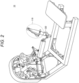
- an operator such as a doctor operates a master unit including the input interface, and a slave unit including a medical instrument such as forceps, tweezers, or an endoscope is remotely operated in accordance with the operation of the master unit by the operator.
- the slave unit is configured as, for example, an arm device in which a surgical tool is held at the distal end, and can change the position or posture of the surgical tool in the abdominal cavity.
- Patent Document 1 discloses a technique for controlling the position and posture of a slave-side camera on the basis of the position and posture of a head mounted display worn by a user.
- Prior art further includes US 2017/172675 A1 , WO 2017/210101 A1 , US 2003/198393 A1 and US 2008/297590 A1 .
- US 2017/172675 A1 discloses a teleoperational medical system for performing a medical procedure in a surgical field.
- the teleoperational system comprises an eye tracking unit and a control unit.
- the eye tracking unit includes an image display configured to display to a user an image of the surgical field, at least one eye tracker configured to measure data about a gaze point of the user, and a processor configured to process the data to determine a viewing location in the displayed image at which the gaze point of the user is directed.
- the control unit is configured to control at least one function of the teleoperational medical system based upon the determined viewing location. It
- WO 2017/210101 discloses systems, methods, and computer-readable media for robotic surgical device control.
- a system including a robotic arm, an autosteroscopic display, a user image capture device, an image processor, and a controller.
- the robotic arm is coupled to a patient image capture device.
- the autostereoscopic display is configured to display an image of a surgical site obtained from the patient image capture device.
- the image processor configured to identify a location of at least part of a user in an image obtained from the user image capture device.
- the controller is configured to, in a first mode, adjust a three dimensional aspect of the image displayed on autostereoscopic display based on the identified location, and, in a second mode, move the robotic arm or instrument based on a relationship between the identified location and the surgical site image.
- Patent Document 1 Japanese Patent Application Laid-Open No. 2004-213673
- control by the control device according to the present embodiment will be described in detail.
- the master slave system 1 is a surgical system used for endoscopic surgery or the like, but the type of the master slave system 1 is not particularly limited.
- the master slave system 1 may be a robot control system that remotely controls a robot.
- the detection unit 30 is configured to detect an eye of a user (observer).
- the detection unit 30 has an imaging function, and can detect the eye of the user appearing in the image by analyzing the image acquired by imaging.
- a tracker a device for tracking the user's eye
- a marker a mark for detecting the user's eye
- the method of detecting the user's eye by the detection unit 30 is not necessarily limited thereto.
- the target detected by the detection unit 30 may be the one equivalent to the eye (for example, a point near the eye, or the like).
- the detection unit 30 provides the control unit 70 with information (hereinafter, referred to as detection information) capable of specifying the position of the eye in the master-side three-dimensional coordinate system.
- detection information may be, for example, position coordinates of the eye in the master-side three-dimensional coordinate system.
- the imaging unit 50 is configured to acquire an image of an affected part by imaging.
- the imaging unit 50 is assumed to be a stereo camera capable of acquiring a stereoscopic image, but is not necessarily limited thereto, and may be, for example, an endoscope or the like.
- the imaging unit 50 according to the present embodiment may include a zoom mechanism and be capable of changing the imaging magnification (zoom magnification).
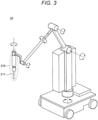
- the imaging unit 50 is supported by the arm 40, and the position and posture of the imaging unit 50 are changed by controlling the angle of the joint of the arm 40 and the like.
- the imaging processing by the imaging unit 50 can be controlled by the control unit 70 described later.
- the control unit 70 is configured to control each of the other components included in the master slave system 1.
- the control unit 70 is connected to each of the other components included in the master slave system 1 by any communication method.
- the control unit 70 receives information measured by a sensor included in the master unit 10 from the master unit 10, and acquires the designated position of the master unit 10 on the basis of the received information. Then, the control unit 70 controls the designated position (for example, the position of the contact portion 211) of the slave unit 20 on the basis of the designated position of the master unit 10, an offset (details will be described later), and the like.
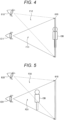
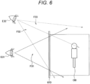
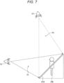
- the stereoscopic display in order to enhance the stereoscopic feeling felt by the user and the feeling as if the object exists in the same space (hereinafter, also referred to as a feeling of coexistence), for example, it is desirable to increase the parallax amount caused by the displacement in the horizontal direction of the image visually recognized by the right eye and the image visually recognized by the left eye.
- the object OB is included in the field of view F1 in a case where the user observes the object OB from a viewpoint E1
- the object OB is included in a field of view F2 in a case where the user observes the object OB from a viewpoint E2. Therefore, the user can observe the object OB from a wider viewpoint position.
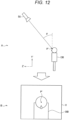
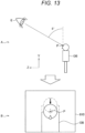
- the control unit 70 calculates a first positional relationship between the eye of the user (observer) observing the object displayed on the display unit 60 and the first point in the master-side three-dimensional coordinate system, and controls the imaging unit 50 so that a second positional relationship between the imaging unit 50 that images the object and the second point corresponding to the first point in the slave-side three-dimensional coordinate system corresponds to the first positional relationship.
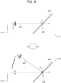
- Fig. 8 is a diagram when a state in which the user looks at the object OB displayed on the display surface 610 is viewed from the lateral direction (in a direction opposite to the X-axis direction).
- XYZ coordinate system XYZ coordinate system
- an angle formed by a line G11 connecting the user's eye E and the first point P at a certain time T11 and the object OB is 90 degrees.
- T12 it is assumed that the position of the user's eye E changes on the YZ plane in the master-side three-dimensional coordinate system.
- an angle formed by a line G12 connecting the user's eye E and the first point P at the time T12 and the object OB changes to ⁇ in the YZ plane.
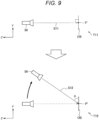
- Fig. 10 is a diagram when a state in which the user looks at the object OB displayed on the display surface 610 is viewed from above (in a direction opposite to the Y-axis direction).
- XYZ coordinate system XYZ coordinate system
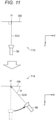
- Fig. 11 is a diagram when a state in which the imaging unit 50 is imaging the object OB is viewed from above (in a direction opposite to the Y'-axis direction).
- an angle formed by a line S13 connecting the imaging unit 50 and the second point P' at a certain time T13 and the object OB is 90 degrees, which is the same as the angle formed by the line G13 connecting the user's eye E and the first point P at the time T13 in Fig. 10 and the object OB.
- the length of the line S13 connecting the imaging unit 50 and the second point P' at the time T13 may be substantially the same as the length of the line G13 connecting the user's eye E and the first point P at the time T13 in Fig. 10 .
- the M S R can also be said to be an offset used for conversion from the three-dimensional coordinate system for the master unit 10 to the three-dimensional coordinate system for the slave unit 20.
- the input V M is converted into output V S of the slave unit 20 on the basis of the rotation matrix of the following Formula 1.
- C the designated position coordinate in the three-dimensional coordinate system for the imaging unit 50 (for example, a camera)
- D the designated position coordinate in the three-dimensional coordinate system for the display unit 60 (for example, a display)
- C and D are set so that the right and left, the up and down, and the normal direction of the imaging unit 50 coincide with the right and left, the up and down, and the normal direction of the display unit 60.
- S C R represents a rotation matrix from S to C (offset used for conversion from three-dimensional coordinate system for slave unit 20 to three-dimensional coordinate system for imaging unit 50)
- C D R represents a rotation matrix from C to D (offset used for conversion from three-dimensional coordinate system of image acquired by imaging unit 50 to three-dimensional coordinate system for display unit 60)
- D M R represents a rotation matrix from D to M (offset used for conversion from three-dimensional coordinate system for display unit 60 to three-dimensional coordinate system for master unit 10).
- control unit 70 may rotate the image by software processing by reflecting the rotation component in the gravity direction in the C D R on the basis of the difference between these angles.
- the angle calculation unit 710 is configured to calculate an angle formed by a line connecting the user's eye and the first point and the object. Specifically, in a case where the detection unit 30 detects the user's eye, the angle calculation unit 710 recognizes the position coordinates of the user's eye in the master-side three-dimensional coordinate system on the basis of the detection information provided from the detection unit 30. Then, the angle calculation unit 710 calculates an angle formed by a line connecting the user's eye and the first point and the object.
- control unit 70 has been described above. Note that the above configuration described with reference to Fig. 14 is merely an example, and the configuration of the control unit 70 is not limited to such an example.
- the control unit 70 may not necessarily include all of the configurations illustrated in Fig. 14 , or may include a configuration not illustrated in Fig. 14 .
- the configuration of the control unit 70 can be flexibly modified depending on specifications and operations.
- Fig. 15 is a flowchart illustrating a processing flow example of each configuration of the master slave system 1 according to the present embodiment.
- each step in the flowchart described above is not necessarily processed in time series in the described order. That is, each step in the flowchart may be processed in an order different from the described order or may be processed in parallel.
- the CPU 901 functions as an arithmetic processing device and a control device, and controls the overall operation in the control unit 70 according to various programs. Furthermore, the CPU 901 may be a microprocessor.
- the ROM 902 stores programs, operation parameters, and the like used by the CPU 901.
- the RAM 903 temporarily stores programs used in the execution of the CPU 901, parameters that appropriately change in the execution, and the like.
- the CPU 901, the ROM 902, and the RAM 903 are mutually connected by a host bus 904a including a CPU bus and the like.
- the host bus 904a is connected to the external bus 904b such as a peripheral component interconnect/interface (PCI) bus via the bridge 904.
- PCI peripheral component interconnect/interface
- the host bus 904a, the bridge 904, and the external bus 904b do not necessarily need to be configured separately, and these functions may be implemented on one bus.
- the control device calculates the first positional relationship between the eye of the user (observer) observing the object displayed on the display unit 60 and the first point in the master-side three-dimensional coordinate system, and controls the imaging unit 50 so that the second positional relationship between the imaging unit 50 that images the object and the second point corresponding to the first point in the slave-side three-dimensional coordinate system corresponds to the first positional relationship.
- the user can observe the object to look around from various directions of up, down, left, and right of the object by changing the position of the eye, so that the user can more intuitively observe the object.
Landscapes
- Engineering & Computer Science (AREA)
- Health & Medical Sciences (AREA)
- Multimedia (AREA)
- Signal Processing (AREA)
- Robotics (AREA)
- General Engineering & Computer Science (AREA)
- Life Sciences & Earth Sciences (AREA)
- Surgery (AREA)
- Theoretical Computer Science (AREA)
- Mechanical Engineering (AREA)
- Nuclear Medicine, Radiotherapy & Molecular Imaging (AREA)
- Molecular Biology (AREA)
- Medical Informatics (AREA)
- Veterinary Medicine (AREA)
- Public Health (AREA)
- General Health & Medical Sciences (AREA)
- General Physics & Mathematics (AREA)
- Physics & Mathematics (AREA)
- Biomedical Technology (AREA)
- Heart & Thoracic Surgery (AREA)
- Animal Behavior & Ethology (AREA)
- Human Computer Interaction (AREA)
- Gynecology & Obstetrics (AREA)
- Pathology (AREA)
- Oral & Maxillofacial Surgery (AREA)
- Radiology & Medical Imaging (AREA)
- Endoscopes (AREA)
- Processing Or Creating Images (AREA)
- User Interface Of Digital Computer (AREA)
- Manipulator (AREA)
Claims (12)
- Steuervorrichtung, umfassend eine Steuereinheit (70), die:von einer Erkennungseinheit (30) Erkennungsinformationen erfasst, die eine Position eines Auges eines Beobachters spezifizieren, der ein Objekt, das auf einer Anzeigeeinheit (60) angezeigt wird, in einem Master-seitigen dreidimensionalen Koordinatensystem beobachtet, wobei die Anzeigeeinheit (60) eine stereoskopische Anzeige ist, die an einer stationären Vorrichtung montiert ist; undbasierend auf den Erkennungsinformationen eine erste Positionsbeziehung zwischen dem Auge des Beobachters und einem ersten Punkt in dem Master-seitigen dreidimensionalen Koordinatensystem berechnet,dadurch gekennzeichnet, dass die Steuereinheit die Position und den Rotationswinkel einer Abbildungseinheit (50), die das Objekt abbildet, so steuert, dass eine zweite Positionsbeziehung zwischen der Abbildungseinheit (50) und einem zweiten Punkt, der dem ersten Punkt in einem Slave-seitigen dreidimensionalen Koordinatensystem entspricht, der ersten Positionsbeziehung entspricht.
- Steuervorrichtung nach Anspruch 1, wobei die Steuereinheit:eine erste Beobachtungsrichtung des Auges des Beobachters in Bezug auf den ersten Punkt in dem Master-seitigen dreidimensionalen Koordinatensystem berechnet; undeine zweite Beobachtungsrichtung der Abbildungseinheit in Bezug auf den zweiten Punkt so steuert, dass die zweite Beobachtungsrichtung der ersten Beobachtungsrichtung in dem Slave-seitigen dreidimensionalen Koordinatensystem entspricht.
- Steuervorrichtung nach Anspruch 2, wobei
die Steuereinheit die zweite Beobachtungsrichtung so steuert, dass die zweite Beobachtungsrichtung und die erste Beobachtungsrichtung im Wesentlichen gleich sind. - Steuervorrichtung nach Anspruch 3, wobei
die Steuereinheit die zweite Beobachtungsrichtung so steuert, dass ein Winkel der ersten Beobachtungsrichtung in Bezug auf eine Schwerkraftrichtung und ein Winkel der zweiten Beobachtungsrichtung in Bezug auf die Schwerkraftrichtung im Wesentlichen gleich sind. - Steuervorrichtung nach Anspruch 2, wobei
die Steuereinheit die zweite Beobachtungsrichtung durch Steuern eines Arms, der die Abbildungseinheit trägt, steuert. - Steuervorrichtung nach Anspruch 2, wobei
die Steuereinheit einen Parameter steuert, um Formel 1 zu erfüllen, wenn M SR eine Rotationsmatrix ist, die für eine Konvertierung von einem dreidimensionalen Koordinatensystem für eine Master-Einheit, die eine Eingabe von dem Beobachter empfängt, in ein dreidimensionales Koordinatensystem für eine Slave-Einheit, die auf einer Basis der Eingabe gesteuert wird, verwendet wird, S CR eine Rotationsmatrix ist, die für die Konvertierung von dem dreidimensionalen Koordinatensystem für die Slave-Einheit in ein dreidimensionales Koordinatensystem für die Abbildungseinheit verwendet wird, C DR eine Rotationsmatrix ist, die für die Konvertierung von dem dreidimensionalen Koordinatensystem für die Abbildungseinheit in ein dreidimensionales Koordinatensystem für die Anzeigeeinheit verwendet wird, D MR eine Rotationsmatrix ist, die für die Konvertierung von dem dreidimensionalen Koordinatensystem für die Anzeigeeinheit in das dreidimensionale Koordinatensystem für die Master-Einheit verwendet wird, und I eine Einheitsmatrix ist.
[Math. 1]
- Steuervorrichtung nach Anspruch 6, wobei
die Steuereinheit die M SR, die S CR oder die C DR durch Steuern eines Parameters dynamisch ändert. - Steuervorrichtung nach Anspruch 6, wobei
die Steuereinheit eine Rotationskomponente in der Schwerkraftrichtung in der C DR auf einer Basis einer Differenz zwischen einem Winkel der ersten Beobachtungsrichtung in Bezug auf eine Schwerkraftrichtung und einem Winkel der zweiten Beobachtungsrichtung in Bezug auf die Schwerkraftrichtung widerspiegelt. - Steuervorrichtung nach Anspruch 1, wobei
der zweite Punkt ein beliebiger eines Aktionspunkts in einer Slave-Einheit, eines Mittelpunkts zwischen zwei Aktionspunkten in der Slave-Einheit, eines Punkts, der in dem Objekt eingeschlossen ist, eines fokussierten Punkts der Abbildungseinheit oder eines Punkts ist, der in einem Betriebsbereich der Slave-Einheit eingeschlossen ist. - Steuervorrichtung nach Anspruch 1, wobei
die Steuereinheit eine Slave-Einheit auf einer Basis des zweiten Punkts steuert. - Steuervorrichtung nach Anspruch 1, wobei
ein Raum auf der Slave-Seite ein realer Raum oder ein virtueller Raum ist. - Master-Slave-System (1), umfassend:eine Slave-Einheit (20);eine Master-Einheit (10), die verwendet wird, um die Slave-Einheit zu betreiben; unddie Steuervorrichtung nach Anspruch 1.
Applications Claiming Priority (2)
| Application Number | Priority Date | Filing Date | Title |
|---|---|---|---|
| JP2019067046A JP2020162916A (ja) | 2019-03-29 | 2019-03-29 | 制御装置及びマスタスレーブシステム |
| PCT/JP2020/010797 WO2020203139A1 (ja) | 2019-03-29 | 2020-03-12 | 制御装置及びマスタスレーブシステム |
Publications (3)
| Publication Number | Publication Date |
|---|---|
| EP3950231A1 EP3950231A1 (de) | 2022-02-09 |
| EP3950231A4 EP3950231A4 (de) | 2022-06-08 |
| EP3950231B1 true EP3950231B1 (de) | 2024-07-10 |
Family
ID=72668695
Family Applications (1)
| Application Number | Title | Priority Date | Filing Date |
|---|---|---|---|
| EP20784850.8A Active EP3950231B1 (de) | 2019-03-29 | 2020-03-12 | Steuerungsvorrichtung und master-slave-system |
Country Status (5)
| Country | Link |
|---|---|
| US (1) | US11582438B2 (de) |
| EP (1) | EP3950231B1 (de) |
| JP (1) | JP2020162916A (de) |
| CN (1) | CN113613847B (de) |
| WO (1) | WO2020203139A1 (de) |
Families Citing this family (5)
| Publication number | Priority date | Publication date | Assignee | Title |
|---|---|---|---|---|
| US20240342920A1 (en) | 2021-04-30 | 2024-10-17 | Sony Group Corporation | Control system, control method, and camera control device |
| CN113349939B (zh) * | 2021-07-12 | 2023-03-21 | 哈尔滨思哲睿智能医疗设备股份有限公司 | 被动主手式主从控制手术机器人的性能测试方法及系统 |
| JP7573505B2 (ja) * | 2021-10-08 | 2024-10-25 | 三菱電機株式会社 | 遠隔検査装置及び遠隔検査方法 |
| US20250057617A1 (en) * | 2022-01-21 | 2025-02-20 | Sony Group Corporation | Surgical robot system |
| JP2024003621A (ja) * | 2022-06-27 | 2024-01-15 | 川崎重工業株式会社 | 手術支援システムおよび手術支援システムの制御方法 |
Family Cites Families (24)
| Publication number | Priority date | Publication date | Assignee | Title |
|---|---|---|---|---|
| JP3026716B2 (ja) * | 1994-03-16 | 2000-03-27 | 株式会社日立製作所 | 立体型表示装置 |
| JPH09147142A (ja) | 1995-11-24 | 1997-06-06 | Nippon Telegr & Teleph Corp <Ntt> | 表示方法及び装置 |
| US6917715B2 (en) * | 2002-04-19 | 2005-07-12 | International Business Machines Corporation | Foveal priority in stereoscopic remote viewing system |
| SE0203908D0 (sv) | 2002-12-30 | 2002-12-30 | Abb Research Ltd | An augmented reality system and method |
| US20080297590A1 (en) | 2007-05-31 | 2008-12-04 | Barber Fred | 3-d robotic vision and vision control system |
| US8543240B2 (en) * | 2009-11-13 | 2013-09-24 | Intuitive Surgical Operations, Inc. | Master finger tracking device and method of use in a minimally invasive surgical system |
| US8682489B2 (en) * | 2009-11-13 | 2014-03-25 | Intuitive Sugical Operations, Inc. | Method and system for hand control of a teleoperated minimally invasive slave surgical instrument |
| US8935003B2 (en) * | 2010-09-21 | 2015-01-13 | Intuitive Surgical Operations | Method and system for hand presence detection in a minimally invasive surgical system |
| US8521331B2 (en) * | 2009-11-13 | 2013-08-27 | Intuitive Surgical Operations, Inc. | Patient-side surgeon interface for a minimally invasive, teleoperated surgical instrument |
| US8996173B2 (en) * | 2010-09-21 | 2015-03-31 | Intuitive Surgical Operations, Inc. | Method and apparatus for hand gesture control in a minimally invasive surgical system |
| WO2014156250A1 (ja) * | 2013-03-29 | 2014-10-02 | オリンパス株式会社 | マスタスレーブシステム |
| CN106456148B (zh) | 2014-03-19 | 2020-06-12 | 直观外科手术操作公司 | 使用眼球凝视跟踪的医疗装置、系统和方法 |
| US20160314717A1 (en) * | 2015-04-27 | 2016-10-27 | KindHeart, Inc. | Telerobotic surgery system for remote surgeon training using robotic surgery station coupled to remote surgeon trainee and instructor stations and associated methods |
| US20160314711A1 (en) * | 2015-04-27 | 2016-10-27 | KindHeart, Inc. | Telerobotic surgery system for remote surgeon training using robotic surgery station and remote surgeon station with display of actual animal tissue images and associated methods |
| US10188552B2 (en) * | 2015-08-14 | 2019-01-29 | The Johns Hopkins University | Surgical system providing hands-free control of a surgical tool |
| US10966798B2 (en) * | 2015-11-25 | 2021-04-06 | Camplex, Inc. | Surgical visualization systems and displays |
| JP2017099820A (ja) | 2015-12-04 | 2017-06-08 | リバーフィールド株式会社 | 操作システム |
| CN108369477B (zh) * | 2015-12-22 | 2021-10-29 | 索尼公司 | 信息处理装置、信息处理方法和程序 |
| WO2017155678A1 (en) * | 2016-03-10 | 2017-09-14 | Kindheart, Inc | Fake blood for use in simulated surgical procedures |
| CN109475387B (zh) * | 2016-06-03 | 2022-07-19 | 柯惠Lp公司 | 用于控制机器人外科手术装置和观看者自适应立体显示器的方面的系统、方法和存储媒体 |
| US20190254759A1 (en) * | 2016-11-04 | 2019-08-22 | Intuitive Surgical Operations, Inc. | Reconfigurable display in computer-assisted tele-operated surgery |
| KR102523945B1 (ko) * | 2016-11-11 | 2023-04-21 | 인튜어티브 서지컬 오퍼레이션즈 인코포레이티드 | 외과의 숙련도 레벨 기반 기구 제어를 갖는 원격조작 수술 시스템 |
| US20180368656A1 (en) * | 2017-05-24 | 2018-12-27 | Camplex, Inc. | Surgical visualization systems and displays |
| US11369443B2 (en) * | 2019-06-27 | 2022-06-28 | Cilag Gmbh International | Method of using a surgical modular robotic assembly |
-
2019
- 2019-03-29 JP JP2019067046A patent/JP2020162916A/ja active Pending
-
2020
- 2020-03-12 CN CN202080023350.3A patent/CN113613847B/zh active Active
- 2020-03-12 WO PCT/JP2020/010797 patent/WO2020203139A1/ja not_active Ceased
- 2020-03-12 US US17/433,237 patent/US11582438B2/en active Active
- 2020-03-12 EP EP20784850.8A patent/EP3950231B1/de active Active
Also Published As
| Publication number | Publication date |
|---|---|
| JP2020162916A (ja) | 2020-10-08 |
| EP3950231A1 (de) | 2022-02-09 |
| CN113613847A (zh) | 2021-11-05 |
| WO2020203139A1 (ja) | 2020-10-08 |
| US20220060678A1 (en) | 2022-02-24 |
| US11582438B2 (en) | 2023-02-14 |
| EP3950231A4 (de) | 2022-06-08 |
| CN113613847B (zh) | 2024-03-19 |
Similar Documents
| Publication | Publication Date | Title |
|---|---|---|
| EP3950231A1 (de) | Steuerungsvorrichtung und master-slave-system | |
| US12414703B2 (en) | Medical device system for remote monitoring and inspection | |
| US12277267B2 (en) | Two-way communication between head-mounted display and electroanatomic system | |
| EP4306057B1 (de) | Tragbares remote-ultraschallabtastsystem und konformitätssteuerungsverfahren für sichere ultraschallabtastung | |
| WO2020006002A1 (en) | Gaze based interface for augmented reality environment | |
| WO2018216382A1 (ja) | 医療用システム、医療用支持アームの制御装置、および医療用支持アームの制御方法 | |
| WO2019225548A1 (ja) | 遠隔操作システム、情報処理方法、及びプログラム | |
| JP2019523663A (ja) | ロボット外科手術装置および視聴者適合型の立体視ディスプレイの態様を制御するためのシステム、方法、およびコンピュータ可読記憶媒体 | |
| JPH07328016A (ja) | 手術用マニピュレータシステム | |
| CN114520048A (zh) | 远程通信装置、手术和治疗系统和远程通信方法 | |
| US12582388B2 (en) | System and apparatus for remote interaction with an object | |
| US11975448B2 (en) | Control device and master-slave system | |
| CN112472298B (zh) | 手术机器人及其控制装置、控制方法 | |
| JP2004344491A (ja) | 仮想手術シミュレーションシステム | |
| US12582382B2 (en) | System and apparatus for remote interaction with an object | |
| US11538315B2 (en) | Tactile sensation presenting device and tactile sensation presenting system | |
| US11992942B2 (en) | Control apparatus, control method, and master-slave system | |
| CN115721421A (zh) | 用于手术机器人主操作手的力反馈方法及装置 | |
| JP2024048960A (ja) | 遠隔手術支援システムおよび指導医側操作装置 | |
| US20250364123A1 (en) | Monitoring of a medical environment by fusion of egocentric and exocentric sensor data | |
| EP4344666A1 (de) | System zur unterstützung einer fernchirurgie | |
| JP2025162718A (ja) | 情報処理装置、情報処理装置の制御方法、及びプログラム | |
| JP2012252663A (ja) | 操作パネル装置および電子情報機器 | |
| JPH09305788A (ja) | 情報処理装置 | |
| JP2024048971A (ja) | 遠隔手術支援システムおよび指導医側操作装置 |
Legal Events
| Date | Code | Title | Description |
|---|---|---|---|
| STAA | Information on the status of an ep patent application or granted ep patent |
Free format text: STATUS: THE INTERNATIONAL PUBLICATION HAS BEEN MADE |
|
| PUAI | Public reference made under article 153(3) epc to a published international application that has entered the european phase |
Free format text: ORIGINAL CODE: 0009012 |
|
| STAA | Information on the status of an ep patent application or granted ep patent |
Free format text: STATUS: REQUEST FOR EXAMINATION WAS MADE |
|
| 17P | Request for examination filed |
Effective date: 20210916 |
|
| AK | Designated contracting states |
Kind code of ref document: A1 Designated state(s): AL AT BE BG CH CY CZ DE DK EE ES FI FR GB GR HR HU IE IS IT LI LT LU LV MC MK MT NL NO PL PT RO RS SE SI SK SM TR |
|
| A4 | Supplementary search report drawn up and despatched |
Effective date: 20220510 |
|
| RIC1 | Information provided on ipc code assigned before grant |
Ipc: A61B 34/00 20160101ALN20220503BHEP Ipc: A61B 34/20 20160101ALN20220503BHEP Ipc: A61B 17/00 20060101ALN20220503BHEP Ipc: B25J 9/16 20060101ALI20220503BHEP Ipc: H04N 13/366 20180101ALI20220503BHEP Ipc: H04N 13/296 20180101ALI20220503BHEP Ipc: H04N 13/221 20180101ALI20220503BHEP Ipc: A61B 90/00 20160101ALI20220503BHEP Ipc: A61B 34/37 20160101ALI20220503BHEP Ipc: B25J 3/00 20060101AFI20220503BHEP |
|
| DAV | Request for validation of the european patent (deleted) | ||
| DAX | Request for extension of the european patent (deleted) | ||
| GRAP | Despatch of communication of intention to grant a patent |
Free format text: ORIGINAL CODE: EPIDOSNIGR1 |
|
| STAA | Information on the status of an ep patent application or granted ep patent |
Free format text: STATUS: GRANT OF PATENT IS INTENDED |
|
| RIC1 | Information provided on ipc code assigned before grant |
Ipc: A61B 34/00 20160101ALN20240122BHEP Ipc: A61B 34/20 20160101ALN20240122BHEP Ipc: A61B 17/00 20060101ALN20240122BHEP Ipc: H04N 23/695 20230101ALI20240122BHEP Ipc: H04N 23/66 20230101ALI20240122BHEP Ipc: G06F 3/01 20060101ALI20240122BHEP Ipc: B25J 9/16 20060101ALI20240122BHEP Ipc: A61B 90/00 20160101ALI20240122BHEP Ipc: A61B 34/37 20160101ALI20240122BHEP Ipc: B25J 3/00 20060101AFI20240122BHEP |
|
| INTG | Intention to grant announced |
Effective date: 20240209 |
|
| RIC1 | Information provided on ipc code assigned before grant |
Ipc: A61B 34/00 20160101ALN20240129BHEP Ipc: A61B 34/20 20160101ALN20240129BHEP Ipc: A61B 17/00 20060101ALN20240129BHEP Ipc: H04N 23/695 20230101ALI20240129BHEP Ipc: H04N 23/66 20230101ALI20240129BHEP Ipc: G06F 3/01 20060101ALI20240129BHEP Ipc: B25J 9/16 20060101ALI20240129BHEP Ipc: A61B 90/00 20160101ALI20240129BHEP Ipc: A61B 34/37 20160101ALI20240129BHEP Ipc: B25J 3/00 20060101AFI20240129BHEP |
|
| GRAS | Grant fee paid |
Free format text: ORIGINAL CODE: EPIDOSNIGR3 |
|
| GRAA | (expected) grant |
Free format text: ORIGINAL CODE: 0009210 |
|
| STAA | Information on the status of an ep patent application or granted ep patent |
Free format text: STATUS: THE PATENT HAS BEEN GRANTED |
|
| P01 | Opt-out of the competence of the unified patent court (upc) registered |
Effective date: 20240514 |
|
| AK | Designated contracting states |
Kind code of ref document: B1 Designated state(s): AL AT BE BG CH CY CZ DE DK EE ES FI FR GB GR HR HU IE IS IT LI LT LU LV MC MK MT NL NO PL PT RO RS SE SI SK SM TR |
|
| REG | Reference to a national code |
Ref country code: CH Ref legal event code: EP |
|
| REG | Reference to a national code |
Ref country code: DE Ref legal event code: R096 Ref document number: 602020033812 Country of ref document: DE |
|
| REG | Reference to a national code |
Ref country code: LT Ref legal event code: MG9D |
|
| REG | Reference to a national code |
Ref country code: NL Ref legal event code: MP Effective date: 20240710 |
|
| PG25 | Lapsed in a contracting state [announced via postgrant information from national office to epo] |
Ref country code: PT Free format text: LAPSE BECAUSE OF FAILURE TO SUBMIT A TRANSLATION OF THE DESCRIPTION OR TO PAY THE FEE WITHIN THE PRESCRIBED TIME-LIMIT Effective date: 20241111 |
|
| REG | Reference to a national code |
Ref country code: AT Ref legal event code: MK05 Ref document number: 1701655 Country of ref document: AT Kind code of ref document: T Effective date: 20240710 |
|
| PG25 | Lapsed in a contracting state [announced via postgrant information from national office to epo] |
Ref country code: NL Free format text: LAPSE BECAUSE OF FAILURE TO SUBMIT A TRANSLATION OF THE DESCRIPTION OR TO PAY THE FEE WITHIN THE PRESCRIBED TIME-LIMIT Effective date: 20240710 |
|
| PG25 | Lapsed in a contracting state [announced via postgrant information from national office to epo] |
Ref country code: PT Free format text: LAPSE BECAUSE OF FAILURE TO SUBMIT A TRANSLATION OF THE DESCRIPTION OR TO PAY THE FEE WITHIN THE PRESCRIBED TIME-LIMIT Effective date: 20241111 Ref country code: NL Free format text: LAPSE BECAUSE OF FAILURE TO SUBMIT A TRANSLATION OF THE DESCRIPTION OR TO PAY THE FEE WITHIN THE PRESCRIBED TIME-LIMIT Effective date: 20240710 |
|
| PG25 | Lapsed in a contracting state [announced via postgrant information from national office to epo] |
Ref country code: NO Free format text: LAPSE BECAUSE OF FAILURE TO SUBMIT A TRANSLATION OF THE DESCRIPTION OR TO PAY THE FEE WITHIN THE PRESCRIBED TIME-LIMIT Effective date: 20241010 |
|
| PG25 | Lapsed in a contracting state [announced via postgrant information from national office to epo] |
Ref country code: GR Free format text: LAPSE BECAUSE OF FAILURE TO SUBMIT A TRANSLATION OF THE DESCRIPTION OR TO PAY THE FEE WITHIN THE PRESCRIBED TIME-LIMIT Effective date: 20241011 Ref country code: FI Free format text: LAPSE BECAUSE OF FAILURE TO SUBMIT A TRANSLATION OF THE DESCRIPTION OR TO PAY THE FEE WITHIN THE PRESCRIBED TIME-LIMIT Effective date: 20240710 Ref country code: PL Free format text: LAPSE BECAUSE OF FAILURE TO SUBMIT A TRANSLATION OF THE DESCRIPTION OR TO PAY THE FEE WITHIN THE PRESCRIBED TIME-LIMIT Effective date: 20240710 |
|
| PG25 | Lapsed in a contracting state [announced via postgrant information from national office to epo] |
Ref country code: BG Free format text: LAPSE BECAUSE OF FAILURE TO SUBMIT A TRANSLATION OF THE DESCRIPTION OR TO PAY THE FEE WITHIN THE PRESCRIBED TIME-LIMIT Effective date: 20240710 |
|
| PG25 | Lapsed in a contracting state [announced via postgrant information from national office to epo] |
Ref country code: LV Free format text: LAPSE BECAUSE OF FAILURE TO SUBMIT A TRANSLATION OF THE DESCRIPTION OR TO PAY THE FEE WITHIN THE PRESCRIBED TIME-LIMIT Effective date: 20240710 |
|
| PG25 | Lapsed in a contracting state [announced via postgrant information from national office to epo] |
Ref country code: AT Free format text: LAPSE BECAUSE OF FAILURE TO SUBMIT A TRANSLATION OF THE DESCRIPTION OR TO PAY THE FEE WITHIN THE PRESCRIBED TIME-LIMIT Effective date: 20240710 Ref country code: IS Free format text: LAPSE BECAUSE OF FAILURE TO SUBMIT A TRANSLATION OF THE DESCRIPTION OR TO PAY THE FEE WITHIN THE PRESCRIBED TIME-LIMIT Effective date: 20241110 |
|
| PG25 | Lapsed in a contracting state [announced via postgrant information from national office to epo] |
Ref country code: HR Free format text: LAPSE BECAUSE OF FAILURE TO SUBMIT A TRANSLATION OF THE DESCRIPTION OR TO PAY THE FEE WITHIN THE PRESCRIBED TIME-LIMIT Effective date: 20240710 |
|
| PG25 | Lapsed in a contracting state [announced via postgrant information from national office to epo] |
Ref country code: ES Free format text: LAPSE BECAUSE OF FAILURE TO SUBMIT A TRANSLATION OF THE DESCRIPTION OR TO PAY THE FEE WITHIN THE PRESCRIBED TIME-LIMIT Effective date: 20240710 Ref country code: RS Free format text: LAPSE BECAUSE OF FAILURE TO SUBMIT A TRANSLATION OF THE DESCRIPTION OR TO PAY THE FEE WITHIN THE PRESCRIBED TIME-LIMIT Effective date: 20241010 |
|
| PG25 | Lapsed in a contracting state [announced via postgrant information from national office to epo] |
Ref country code: RS Free format text: LAPSE BECAUSE OF FAILURE TO SUBMIT A TRANSLATION OF THE DESCRIPTION OR TO PAY THE FEE WITHIN THE PRESCRIBED TIME-LIMIT Effective date: 20241010 Ref country code: PL Free format text: LAPSE BECAUSE OF FAILURE TO SUBMIT A TRANSLATION OF THE DESCRIPTION OR TO PAY THE FEE WITHIN THE PRESCRIBED TIME-LIMIT Effective date: 20240710 Ref country code: NO Free format text: LAPSE BECAUSE OF FAILURE TO SUBMIT A TRANSLATION OF THE DESCRIPTION OR TO PAY THE FEE WITHIN THE PRESCRIBED TIME-LIMIT Effective date: 20241010 Ref country code: LV Free format text: LAPSE BECAUSE OF FAILURE TO SUBMIT A TRANSLATION OF THE DESCRIPTION OR TO PAY THE FEE WITHIN THE PRESCRIBED TIME-LIMIT Effective date: 20240710 Ref country code: IS Free format text: LAPSE BECAUSE OF FAILURE TO SUBMIT A TRANSLATION OF THE DESCRIPTION OR TO PAY THE FEE WITHIN THE PRESCRIBED TIME-LIMIT Effective date: 20241110 Ref country code: HR Free format text: LAPSE BECAUSE OF FAILURE TO SUBMIT A TRANSLATION OF THE DESCRIPTION OR TO PAY THE FEE WITHIN THE PRESCRIBED TIME-LIMIT Effective date: 20240710 Ref country code: GR Free format text: LAPSE BECAUSE OF FAILURE TO SUBMIT A TRANSLATION OF THE DESCRIPTION OR TO PAY THE FEE WITHIN THE PRESCRIBED TIME-LIMIT Effective date: 20241011 Ref country code: FI Free format text: LAPSE BECAUSE OF FAILURE TO SUBMIT A TRANSLATION OF THE DESCRIPTION OR TO PAY THE FEE WITHIN THE PRESCRIBED TIME-LIMIT Effective date: 20240710 Ref country code: ES Free format text: LAPSE BECAUSE OF FAILURE TO SUBMIT A TRANSLATION OF THE DESCRIPTION OR TO PAY THE FEE WITHIN THE PRESCRIBED TIME-LIMIT Effective date: 20240710 Ref country code: BG Free format text: LAPSE BECAUSE OF FAILURE TO SUBMIT A TRANSLATION OF THE DESCRIPTION OR TO PAY THE FEE WITHIN THE PRESCRIBED TIME-LIMIT Effective date: 20240710 Ref country code: AT Free format text: LAPSE BECAUSE OF FAILURE TO SUBMIT A TRANSLATION OF THE DESCRIPTION OR TO PAY THE FEE WITHIN THE PRESCRIBED TIME-LIMIT Effective date: 20240710 |
|
| REG | Reference to a national code |
Ref country code: DE Ref legal event code: R097 Ref document number: 602020033812 Country of ref document: DE |
|
| PG25 | Lapsed in a contracting state [announced via postgrant information from national office to epo] |
Ref country code: RO Free format text: LAPSE BECAUSE OF FAILURE TO SUBMIT A TRANSLATION OF THE DESCRIPTION OR TO PAY THE FEE WITHIN THE PRESCRIBED TIME-LIMIT Effective date: 20240710 Ref country code: SM Free format text: LAPSE BECAUSE OF FAILURE TO SUBMIT A TRANSLATION OF THE DESCRIPTION OR TO PAY THE FEE WITHIN THE PRESCRIBED TIME-LIMIT Effective date: 20240710 Ref country code: DK Free format text: LAPSE BECAUSE OF FAILURE TO SUBMIT A TRANSLATION OF THE DESCRIPTION OR TO PAY THE FEE WITHIN THE PRESCRIBED TIME-LIMIT Effective date: 20240710 |
|
| PG25 | Lapsed in a contracting state [announced via postgrant information from national office to epo] |
Ref country code: EE Free format text: LAPSE BECAUSE OF FAILURE TO SUBMIT A TRANSLATION OF THE DESCRIPTION OR TO PAY THE FEE WITHIN THE PRESCRIBED TIME-LIMIT Effective date: 20240710 |
|
| PG25 | Lapsed in a contracting state [announced via postgrant information from national office to epo] |
Ref country code: CZ Free format text: LAPSE BECAUSE OF FAILURE TO SUBMIT A TRANSLATION OF THE DESCRIPTION OR TO PAY THE FEE WITHIN THE PRESCRIBED TIME-LIMIT Effective date: 20240710 |
|
| PG25 | Lapsed in a contracting state [announced via postgrant information from national office to epo] |
Ref country code: SK Free format text: LAPSE BECAUSE OF FAILURE TO SUBMIT A TRANSLATION OF THE DESCRIPTION OR TO PAY THE FEE WITHIN THE PRESCRIBED TIME-LIMIT Effective date: 20240710 Ref country code: IT Free format text: LAPSE BECAUSE OF FAILURE TO SUBMIT A TRANSLATION OF THE DESCRIPTION OR TO PAY THE FEE WITHIN THE PRESCRIBED TIME-LIMIT Effective date: 20240710 |
|
| PLBE | No opposition filed within time limit |
Free format text: ORIGINAL CODE: 0009261 |
|
| STAA | Information on the status of an ep patent application or granted ep patent |
Free format text: STATUS: NO OPPOSITION FILED WITHIN TIME LIMIT |
|
| 26N | No opposition filed |
Effective date: 20250411 |
|
| PG25 | Lapsed in a contracting state [announced via postgrant information from national office to epo] |
Ref country code: SE Free format text: LAPSE BECAUSE OF FAILURE TO SUBMIT A TRANSLATION OF THE DESCRIPTION OR TO PAY THE FEE WITHIN THE PRESCRIBED TIME-LIMIT Effective date: 20240710 |
|
| PG25 | Lapsed in a contracting state [announced via postgrant information from national office to epo] |
Ref country code: MC Free format text: LAPSE BECAUSE OF FAILURE TO SUBMIT A TRANSLATION OF THE DESCRIPTION OR TO PAY THE FEE WITHIN THE PRESCRIBED TIME-LIMIT Effective date: 20240710 |
|
| REG | Reference to a national code |
Ref country code: CH Ref legal event code: H13 Free format text: ST27 STATUS EVENT CODE: U-0-0-H10-H13 (AS PROVIDED BY THE NATIONAL OFFICE) Effective date: 20251024 |
|
| PG25 | Lapsed in a contracting state [announced via postgrant information from national office to epo] |
Ref country code: LU Free format text: LAPSE BECAUSE OF NON-PAYMENT OF DUE FEES Effective date: 20250312 |
|
| REG | Reference to a national code |
Ref country code: BE Ref legal event code: MM Effective date: 20250331 |
|
| PG25 | Lapsed in a contracting state [announced via postgrant information from national office to epo] |
Ref country code: FR Free format text: LAPSE BECAUSE OF NON-PAYMENT OF DUE FEES Effective date: 20250331 |
|
| PG25 | Lapsed in a contracting state [announced via postgrant information from national office to epo] |
Ref country code: BE Free format text: LAPSE BECAUSE OF NON-PAYMENT OF DUE FEES Effective date: 20250331 |
|
| PG25 | Lapsed in a contracting state [announced via postgrant information from national office to epo] |
Ref country code: CH Free format text: LAPSE BECAUSE OF NON-PAYMENT OF DUE FEES Effective date: 20250331 |
|
| PG25 | Lapsed in a contracting state [announced via postgrant information from national office to epo] |
Ref country code: IE Free format text: LAPSE BECAUSE OF NON-PAYMENT OF DUE FEES Effective date: 20250312 |
|
| PGFP | Annual fee paid to national office [announced via postgrant information from national office to epo] |
Ref country code: GB Payment date: 20260219 Year of fee payment: 7 |
|
| PGFP | Annual fee paid to national office [announced via postgrant information from national office to epo] |
Ref country code: DE Payment date: 20260219 Year of fee payment: 7 |