EP3949385B1 - Phare de véhicule automobile - Google Patents
Phare de véhicule automobile Download PDFInfo
- Publication number
- EP3949385B1 EP3949385B1 EP20708138.1A EP20708138A EP3949385B1 EP 3949385 B1 EP3949385 B1 EP 3949385B1 EP 20708138 A EP20708138 A EP 20708138A EP 3949385 B1 EP3949385 B1 EP 3949385B1
- Authority
- EP
- European Patent Office
- Prior art keywords
- laser light
- microcontroller
- deflection
- light source
- channel
- Prior art date
- Legal status (The legal status is an assumption and is not a legal conclusion. Google has not performed a legal analysis and makes no representation as to the accuracy of the status listed.)
- Active
Links
Images


Classifications
-
- H—ELECTRICITY
- H05—ELECTRIC TECHNIQUES NOT OTHERWISE PROVIDED FOR
- H05B—ELECTRIC HEATING; ELECTRIC LIGHT SOURCES NOT OTHERWISE PROVIDED FOR; CIRCUIT ARRANGEMENTS FOR ELECTRIC LIGHT SOURCES, IN GENERAL
- H05B47/00—Circuit arrangements for operating light sources in general, i.e. where the type of light source is not relevant
- H05B47/10—Controlling the light source
-
- H—ELECTRICITY
- H04—ELECTRIC COMMUNICATION TECHNIQUE
- H04N—PICTORIAL COMMUNICATION, e.g. TELEVISION
- H04N9/00—Details of colour television systems
- H04N9/12—Picture reproducers
- H04N9/31—Projection devices for colour picture display, e.g. using electronic spatial light modulators [ESLM]
- H04N9/3129—Projection devices for colour picture display, e.g. using electronic spatial light modulators [ESLM] scanning a light beam on the display screen
-
- F—MECHANICAL ENGINEERING; LIGHTING; HEATING; WEAPONS; BLASTING
- F21—LIGHTING
- F21S—NON-PORTABLE LIGHTING DEVICES; SYSTEMS THEREOF; VEHICLE LIGHTING DEVICES SPECIALLY ADAPTED FOR VEHICLE EXTERIORS
- F21S41/00—Illuminating devices specially adapted for vehicle exteriors, e.g. headlamps
- F21S41/10—Illuminating devices specially adapted for vehicle exteriors, e.g. headlamps characterised by the light source
- F21S41/14—Illuminating devices specially adapted for vehicle exteriors, e.g. headlamps characterised by the light source characterised by the type of light source
- F21S41/16—Laser light sources
-
- H—ELECTRICITY
- H04—ELECTRIC COMMUNICATION TECHNIQUE
- H04N—PICTORIAL COMMUNICATION, e.g. TELEVISION
- H04N9/00—Details of colour television systems
- H04N9/12—Picture reproducers
- H04N9/31—Projection devices for colour picture display, e.g. using electronic spatial light modulators [ESLM]
- H04N9/3129—Projection devices for colour picture display, e.g. using electronic spatial light modulators [ESLM] scanning a light beam on the display screen
- H04N9/3135—Driving therefor
-
- H—ELECTRICITY
- H05—ELECTRIC TECHNIQUES NOT OTHERWISE PROVIDED FOR
- H05B—ELECTRIC HEATING; ELECTRIC LIGHT SOURCES NOT OTHERWISE PROVIDED FOR; CIRCUIT ARRANGEMENTS FOR ELECTRIC LIGHT SOURCES, IN GENERAL
- H05B47/00—Circuit arrangements for operating light sources in general, i.e. where the type of light source is not relevant
- H05B47/10—Controlling the light source
- H05B47/165—Controlling the light source following a pre-assigned programmed sequence; Logic control [LC]
-
- F—MECHANICAL ENGINEERING; LIGHTING; HEATING; WEAPONS; BLASTING
- F21—LIGHTING
- F21W—INDEXING SCHEME ASSOCIATED WITH SUBCLASSES F21K, F21L, F21S and F21V, RELATING TO USES OR APPLICATIONS OF LIGHTING DEVICES OR SYSTEMS
- F21W2102/00—Exterior vehicle lighting devices for illuminating purposes
- F21W2102/10—Arrangement or contour of the emitted light
- F21W2102/13—Arrangement or contour of the emitted light for high-beam region or low-beam region
Definitions
- the invention relates to a motor vehicle comprising at least one motor vehicle headlight according to the invention.
- the desire to be able to project a light image onto the road that can be quickly changed and adapted to the respective traffic, road and light conditions is always in the foreground.
- Various headlights such as main headlights and auxiliary headlights, are used for this purpose, which project different light patterns onto the road.
- the term "roadway” is used here for the sake of simplicity, because of course it depends on the local conditions whether a photograph is actually on the roadway or extends beyond it.
- the photo corresponds to the used sense of a projection onto a vertical surface according to the relevant standards relating to automotive lighting technology.
- Motor vehicle headlights for generating a variable light distribution can, for example, have one or more light sources that can be modulated in terms of the intensity of radiation, with light beams emitted thereby being able to be projected onto a roadway via a pivotable reflector unit.
- control of the light sources in the form of a modulation of the intensity of the emitted light, as well as the precise control of the pivoting or reflector unit, is often complex and difficult, since, for example, control signals that are not exactly synchronous in time can become noticeable in an undesirable impairment of the projected light image. which can even make it difficult to comply with legal limit values.
- a correspondingly suitable control of such a motor vehicle headlight can be complicated and expensive.
- the direct memory access (DMA, "Direct Memory Access”) is used for data transport between the main memory and the peripherals, which can be, for example, separately designed modules and is a conceptual circuit and control measure that uses special data lines to connect the modules and the main memory self-made. This allows data to be written directly to memory without going through the processor, and in the reverse direction from memory to module, while having less impact on processor execution speed for running programs. In other words, DMA relieves the processor. In addition to an increase in speed for memory-intensive applications, the use of DMA controllers also enables very high data rates.
- DMA Direct Memory Access
- a DMA index may only be assigned to one device.
- the index indicates the number of the DMA channel.
- 8 DMA channels can be provided.
- channels 0, 2 and 4 can already be assigned for internal purposes and channels 1, 3, 5, 6 and 7 can be freely assigned.
- the channels can also be configured very extensively and can be transferred individually or in blocks with 8, 16 and 32 bits.
- the DMA controller is already integrated in modern chip sets of processors or microcontrollers.
- the microcontroller 100 has a DMA controller and a compare register, with the microcontroller 100 being set up to compare the timer with a value made available via a DMA channel in order to Determination of value equality does not trigger an interrupt operation, but a DMA operation, which is used to determine the timing of the control according to points a) and b).
- the motor vehicle headlight has at least two laser light sources, preferably three, four, five or more laser light sources, which are set up to emit light onto the deflection device and thus onto the conversion means, the emission of the laser light sources onto the conversion means being offset in this way in relation to one another is that line-shaped form-fitting side by side and / or superimposed conversion areas on the conversion means by horizontal and/or vertical deflection of the laser light from the laser light sources can be illuminated, with each laser light source being assigned a section of the conversion area, the deflection device for deflecting the laser light from the laser light sources having at least one controllable mirror, it being possible in particular for provision to be made for a plurality of controllable mirrors to be provided, by means of which the deflection of the laser light can be carried out individually.
- the microcontroller is set up to serially transmit at least one brightness data set for controlling the at least one laser light source via a data bus to the modulation unit, the brightness data set containing a field of data entries, each data entry containing the target brightness of a pixel predetermined height and width in the light image of a light distribution of a laser light source, wherein each laser light source is assigned a light channel of the modulation unit, each light channel being supplied with a common clock signal via a clock line and a control signal via a control line, with each light channel being assigned a channel converter, wherein each channel converter is set up to receive the at least one brightness data set from the data bus serially, taking the clock signal into account, and to successively transmit the at least one brightness data set in parallel via a final bus assigned to each channel converter if a control signal is sent via one of the Modulation unit associated control line is received by the microcontroller.
- the invention can include two, three, four, five or more light channels.
- each final bus of the modulation unit can be assigned a digital-to-analog converter, with each digital-to-analog converter being is set up to receive the at least one brightness data set from the final bus in parallel and to convert it into an analog driver signal for the respective laser light source.
- each digital-to-analog converter is designed as an R/2R network.
- DMA controller This is a co-processor to offload the core when copying data from A to B in memory. This is used, for example, when handling large amounts of data on external interfaces of the microcontroller (SPI, UART, ). The data is copied to a memory address with almost no influence on the main program.
- the laser channels are modulated by a second group of DMA operations, which are triggered by pixel timing via a DMA link.
- a DMA channel writes the brightness data column by column from an array of brightness data into an intermediate buffer. This is used to regroup the data for the next step and can also be omitted depending on the internal structure.
- the data from the intermediate buffer is written to the intended modulation interface by another linked DMA channel.
- an interface can be, for example, a GPIO pin register, a PWM register or a communication interface such as SPI.
- Another advantage of this concept is the scalability, which is only limited by the existing DMA channels and the necessary control frequency, for use for several laser channels or a 2D concept, i.e. a concept in which a laser beam can be deflected along two axes oriented normal to one another.
- a headlight contains many other parts that are not shown and that allow sensible use in a motor vehicle, such as in particular a car or motorcycle.
- cooling devices for components, further control electronics, further optical elements, mechanical adjustment devices or holders or housings are not shown.
- the same reference symbols designate the same features in the following figures.
- a microcontroller 100 is assigned to the modulation unit 200 for the digital conversion or processing of the time control.
- the microcontroller 100 has at least one timer and a DMA controller, the Microcontroller 100 is set up to trigger DMA operations directly as a function of the timer, by means of which the temporal and spatial control takes place in accordance with points a) and b).
- a vehicle headlight 1 in which laser beams are generated by light sources 10-12, for example in the form of semiconductor light sources such as laser diodes, and are deflected by means of a deflection device 2 onto a conversion element 4 and subsequently in the direction of emission of the vehicle headlight 1, in which projection optics 3 , for example in the form of an array of one or more lenses.
- the deflection device 2 is designed, for example, as a micro-deflection unit with a controllable micro-mirror, which is set up to deflect the laser beams of the light sources 10-12 at a deflection angle 20.
- a conversion element 4 is arranged in the beam path between the deflection device 2 and the projection optics 3 in order, for example, to convert UV light or blue laser light generated by the light sources 10-12 into white visible light.
- the conversion element 4 can be transparent (transmissive) or at least partially reflective, in particular as a phosphor.
- the vehicle headlight includes a microcontroller 100, which is connected to the light sources 10-12 and the deflection device 2 to control them.
- the motor vehicle headlight 1 which is intended for installation in a vehicle, comprises three light sources 10-12, a deflection device 2, a conversion element 4 and projection optics 3 in the form of a projection lens, as well as a microcontroller 100 and an electronic circuit which will be discussed in more detail below.
- the light sources 10-12 are set up to emit light in the direction of the deflection device 2.
- the deflection device 2 is set up to deflect the emitted light distribution onto the conversion element 4 and subsequently onto the projection optics 3 .
- the deflection device 2 can be configured by a control device using a set of deflection parameters.
- the conversion element 4 shows schematically the conversion element 4 with a conversion surface, via which the laser beam or beams are very quickly deflected in the horizontal direction (as indicated by arrows therein), and write a luminescent image, which is then recorded as a light distribution via projection optics 3 in the direction of emission 5 the street is projected.
- the emission direction 5 can be defined, for example, by a zero position in which the deflection mirror is not adjusted.
- a block diagram of an electronic circuit in which a deflection device 2 and three light channels 210-212 can be controlled by a microcontroller 100.
- inventions may include one, two, four, five or more light channels.
- the circuit shows the microcontroller 100, which has a timer unit 110, a memory 120, an intermediate buffer 130 and a peripheral control device 140. It is clear that the microcontroller 100 has further functional units, for example an arithmetic logic unit, registers, communication interfaces, input/output interfaces, analog/digital converters, program memory, etc.
- microcontroller 100 has a DMA function, which is not shown separately in the figures, but is described in more detail below.
- the microcontroller 100 is provided for controlling the respective lighting channels 210-212.
- the 4 and 5 show an exemplary embodiment of a modulation device 200 for driving the light channels 210-212.
- the light sources 10-12 of the individual lighting channels 210-212 are controlled by means of digital-to-analog converters 220-222.
- Each lighting channel 210-212 can be controlled by the microcontroller 100 via a parallel, final bus 270-272, each of which comprises eight bus lines.
- the microcontroller 100 has a data interface or a data output via which a data signal is transmitted.
- the three lighting channels 210-212 each include a channel converter 230-232, a digital-to-analog converter 220-222 and the light source 10-12.
- the channel converters 230-232 are each a shift register, but other logic circuits can also be suitable for this, such as data buses according to the RS-232 or USB standard. It is clear that when several lines are linked to form a data bus, in particular a serial bus, circuit logic may be required which is set up to receive serial signals via a serial input, to store them if necessary, and again via a serial output to send and thereby create a chained serial bus. It is clear to a person skilled in the art that a corresponding architecture can be created for a parallel bus, with the disadvantages mentioned at the beginning having to be taken into account accordingly when implementing a parallel bus.
- a daisy-chain architecture can also be used for the second bus, in which a serial input corresponds to the serial output of a module connected to the architecture. It may be necessary, for example, for a logic circuit to allocate the received serial data to the respective lighting channels. This variant is not shown.
- Microcontroller 100 is set up to transmit at least one brightness data record for controlling light source 10-12 serially via a second bus 240 to the three lighting channels 210-212 and to control it with a clock signal via a clock line 251 and a control signal via a control line 260.
- Each channel converter 230-232 is set up to receive the at least one brightness data set from the second bus 240 serially using the clock signal from the clock line 251 and the at least one brightness data set via each channel converter 230-232 associated final bus 270-272 in parallel when a control signal is received via the control line 260 from the microcontroller 100.
- Each digital-to-analog converter 220-222 is set up to receive the at least one brightness data set from the final bus 270-272 in parallel and to convert it into an analog driver signal for each of the light sources 10-12.
- the light sources 10-12 are each set up to be driven with the analog drive signal via a drive line 345, and the brightness of the light source 10-12 is controlled in accordance with the analog drive signal.
- the light source 10-12 is set up to emit light in the direction of the deflection device 2, from where it is deflected and, when installed in a vehicle, projects a light image onto the roadway in front of the vehicle.
- the clock generator 115 contained in the microcontroller 100 also generates a module clock signal 451 for operating the channel converters 230-232.
- the system clock signal 450 is also used to control the deflection device 2.
- the three lighting channels 210-212 whose respective channel converters 230-232 are connected in series one after the other by means of the second bus 240, each contain a preceding channel converter 230, 231 and a following channel converter 231, 232.
- the respectively preceding channel converter 230, 231 is arranged in the sequence on the second bus 240 before the respectively following channel converter 230, 231.
- the respectively preceding channel converter 231, 232 has a data output 244, 245 which is connected to the serial data input 242-243 of the respectively following channel converter 231, 232 by means of the second bus 240.
- the respective preceding channel converter 230-232 is set up to receive light data from the data input 242, 243 with the aid of the module clock signal 451 and to output it again via the data output 244, 245.
- the first bus 270-272 is a parallel bus in this embodiment.
- the second bus 240 is a serial bus in this embodiment.
- the channel converter 230-232 of the at least one lighting channel 210-212 is a serial-to-parallel converter in each case in this exemplary embodiment.
- the first serial-to-parallel converter or channel converter 230 is placed first in the sequence on the serial bus or second bus 240 .
- the three lighting channels 210-212 whose serial-to-parallel converters 230-232 are connected in series one after the other by means of the serial bus 240, have a last serial-to-parallel converter 232.
- the last serial to parallel converter 232 is placed last in the sequence on the serial bus 240 .
- the lighting channels 210-212 are all connected to the same serial bus 240 in this example.
- the figure 5 shows a preferred embodiment variant of a digital-to-analog converter 220-222 using an R/2R network, which converts digital values into an analog voltage and a light source 10 using a driver circuit formed from two operational amplifiers 340, 341 and a power transistor 350 is, drives.
- a series resistor 360 is used to adjust the current through the light source 10, here in the form of a laser diode.
- the R/2R resistance network followed by one or more operational amplifiers 340, 341 and the transistor 350, which acts as a modulator, is simpler for the intended application in a vehicle headlight 1 and also cheaper than, for example, an integrated circuit.
- a driver line 345 connects a first circuit portion forming the digital-to-analog converter 220-222 and a second circuit portion forming the driver of the light source 10-12.
- the driver line 345 connects the two operational amplifiers 340, 341.
- the operational amplifiers 340, 341 are provided for decoupling the first from the second circuit part. Otherwise the most significant digital input 10, i.e. the highest bit of the brightness data record, would have to take on a high proportion of the output load of the R/2R resistor network 220-222 when the digital input signal is set, i.e. when the bit is set.
- the R/2R network is made up of resistors 320-327 and 330-338 with values R and 2R.
- the individual digital inputs 310-317 are either at ground or at the reference voltage. Each digital input thus contributes its specific part to the resulting output voltage.
- R/2R network The advantages of an R/2R network include the very high digital-to-analog conversion speed combined with very high accuracy, as well as the simple structure using identical, inexpensive components.
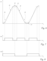
- FIG. 6 shows the course over time of the deflection angle 20 of the deflection device 2.
- An approximately linear range 25 with a positive slope can be seen in the course, which corresponds to the deflection of the deflection device 2 in a first direction 21, as well as an approximately linear range 25 with a negative slope , which corresponds to the deflection of the deflection device 2 in a second direction 22 .
- the light sources 10-12 are activated simultaneously, which emit light onto the deflection device 2, and which is emitted by the deflection device 2 in the emission direction 5 of the Headlight 1 is deflected.
- the feedback signal 201 during the generation of the modulation of the light sources 10-12 can be used.
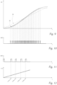
- a section of the time profile of the deflection angle 20 is shown with a positive slope, in which additional sections can be seen from which the profile is composed.
- the subdivision into partial sections serves to improve the course 25 of the deflection of the deflection angle 20 of the deflection device 2, which is not exactly linear.
- deviations in the actual profile 25 from an ideal, linear profile 26 can be partially corrected.
- FIG. 10 shows the time course of the control signal 460 in connection with the mentioned sections, and 11 an enlarged view of a section of the 10 .
- the actual value of the deflection angle 20 provided for the respective section is reached with a rising edge of the control signal 460 in each case.
- the deviation between the actual values and the associated setpoint values results in different time durations between the pulses of the control signal 460, which preferably each have a constant pulse duration.
- a correction of an actual value according to the actual curve 25 compared to the respective target value according to the ideal curve 26 can thus be achieved.
- the pulses of the control signal 460 would each have the same period duration or the same duty cycle.
Landscapes
- Physics & Mathematics (AREA)
- Optics & Photonics (AREA)
- Engineering & Computer Science (AREA)
- Multimedia (AREA)
- Signal Processing (AREA)
- General Engineering & Computer Science (AREA)
- Lighting Device Outwards From Vehicle And Optical Signal (AREA)
Claims (4)
- Projecteur de véhicule automobile (1), comprenant- au moins une source de lumière laser (10, 11, 12),- un moyen de conversion (4) pouvant être irradié et excité par ladite au moins une source de lumière laser (10, 11, 12) pour émettre de la lumière visible,- au moins un dispositif de déviation (2) commandable, disposé sur le trajet du faisceau entre la au moins une source de lumière laser (10, 11, 12) et le moyen de conversion (4), pour la déviation spatiale de la lumière laser à l'intérieur d'une zone de conversion (40, 41, 42) du moyen de conversion (4) pouvant être reproduite en une répartition de lumière,- une optique de projection (3) pour représenter la lumière convertie à l'intérieur de la zone de conversion (40, 41, 42) en une répartition de lumière pouvant être projetée sur une surface, et- au moins un dispositif de modulation (200)caractérisé en ce quea) pour la commande temporelle de l'intensité de la lumière laser émise par l'au moins une source de lumière laser (10, 11, 12), ainsi queb) pour commander la déviation spatiale de la lumière laser par le dispositif de déviation (2), un microcontrôleur (100) étant associé au dispositif de modulation (200) pour la conversion numérique de la commande temporelle,
le microcontrôleur (100) comporte au moins une minuterie et un contrôleur d'accès direct à la mémoire (contrôleur DMA), le microcontrôleur (100) étant conçu pour déclencher directement, en fonction de la minuterie, des opérations DMA au moyen desquelles s'effectue la commande temporelle et spatiale selon les points a) et b), le microcontrôleur (100) comportant un contrôleur DMA et un registre de comparaison, le microcontrôleur (100) étant conçu pour comparer la minuterie avec une valeur mise à disposition par un canal DMA, afin de ne pas déclencher une opération d'interruption en cas de constatation d'une égalité de valeurs, mais une opération DMA qui est utilisée pour déterminer la séquence temporelle de la commande selon les points a) et b), le projecteur de véhicule automobile (1) présentant au moins deux sources de lumière laser (10, 11, 12), de préférence trois, quatre cinq sources de lumière laser ou plus, qui sont conçues pour émettre de la lumière sur le dispositif de déviation (2) et donc sur le moyen de conversion (4), l'émission des sources de lumière laser (10, 11, 12) sur le moyen de conversion (4) étant décalée l'une par rapport à l'autre de telle manière, que des zones de conversion (40, 41, 42) juxtaposées et/ou superposées en forme de lignes peuvent être éclairées sur le moyen de conversion (4) par déviation horizontale et/ou verticale de la lumière laser des sources de lumière laser (10, 11, 12), une section de la zone de conversion (40, 41, 42) étant associée à chaque source de lumière laser (10, 11, 12), le dispositif de déviation (2) présentant, pour la déviation de la lumière laser des sources de lumière laser (10, 11, 12), au moins un miroir commandable, étant entendu qu'il peut être prévu en particulier que plusieurs miroirs commandables sont prévus, au moyen desquels la déviation de la lumière laser peut être effectuée individuellement, le microcontrôleur (100) étant conçu pour transmettre en série au dispositif de modulation (200) au moins un jeu de données de luminosité pour la commande de l'au moins une source de lumière laser (10, 11, 12) par l'intermédiaire d'un bus de données (240), le jeu de données de luminosité contenant un champ d'entrées de données, chaque entrée de données représentant la luminosité de consigne d'un pixel de hauteur et de largeur prédéfinies dans l'image lumineuse d'une répartition lumineuse d'une source de lumière laser (10, 11, 12), un canal lumineux (210, 211, 212) du dispositif de modulation (200) étant associé à chaque source de lumière laser (10, 11, 12), un signal d'horloge commun étant amené à chaque canal lumineux (210, 211, 212) par l'intermédiaire d'une ligne d'horloge (251) et un signal de commande par l'intermédiaire d'une ligne de commande (260), un convertisseur de canal (230, 231, 232) étant associé à chaque canal lumineux (210, 211, 212), chaque convertisseur de canal (230, 231, 232) étant conçu pour recevoir en série l'au moins un ensemble de données de luminosité du bus de données (240) en tenant compte du signal d'horloge et pour transmettre en parallèle l'au moins un ensemble de données de luminosité successivement par l'intermédiaire d'un bus final (270-272) associé à chaque convertisseur de canal (230-232) lorsqu'un signal de commande est reçu par le microcontrôleur (100) par l'intermédiaire de la ligne de commande (260) associée au dispositif de modulation, un convertisseur numérique-analogique (220-222) étant associé à chaque bus final (270-272) du dispositif de modulation (200), chaque convertisseur numérique-analogique (220-222) étant conçu pour recevoir en parallèle l'au moins un ensemble de données de luminosité provenant du bus final (270-272) et pour le convertir respectivement en un signal de commande analogique pour la source de lumière laser respective (10, 11, 12). - Projecteur de véhicule automobile (1) selon la revendication 1, dans lequel chaque convertisseur numérique-analogique est conçu comme un réseau R/2R.
- Projecteur de véhicule automobile (1) selon la revendication 1 ou 2, dans lequel la transmission de l'au moins un jeu de données de luminosité du microcontrôleur (100) vers le dispositif de modulation (200) s'effectue par une interface sérielle périphérique (SPI) via le bus de données (240).
- Véhicule automobile comprenant au moins un, de préférence deux, projecteur(s) de véhicule automobile (1) selon l'une quelconque des revendications précédentes.
Applications Claiming Priority (2)
| Application Number | Priority Date | Filing Date | Title |
|---|---|---|---|
| EP19167536.2A EP3720124A1 (fr) | 2019-04-05 | 2019-04-05 | Phare de véhicule automobile |
| PCT/EP2020/056468 WO2020200677A2 (fr) | 2019-04-05 | 2020-03-11 | Phare de véhicule à moteur |
Publications (2)
| Publication Number | Publication Date |
|---|---|
| EP3949385A2 EP3949385A2 (fr) | 2022-02-09 |
| EP3949385B1 true EP3949385B1 (fr) | 2023-05-10 |
Family
ID=66101923
Family Applications (2)
| Application Number | Title | Priority Date | Filing Date |
|---|---|---|---|
| EP19167536.2A Withdrawn EP3720124A1 (fr) | 2019-04-05 | 2019-04-05 | Phare de véhicule automobile |
| EP20708138.1A Active EP3949385B1 (fr) | 2019-04-05 | 2020-03-11 | Phare de véhicule automobile |
Family Applications Before (1)
| Application Number | Title | Priority Date | Filing Date |
|---|---|---|---|
| EP19167536.2A Withdrawn EP3720124A1 (fr) | 2019-04-05 | 2019-04-05 | Phare de véhicule automobile |
Country Status (3)
| Country | Link |
|---|---|
| EP (2) | EP3720124A1 (fr) |
| CN (1) | CN113661785B (fr) |
| WO (1) | WO2020200677A2 (fr) |
Families Citing this family (1)
| Publication number | Priority date | Publication date | Assignee | Title |
|---|---|---|---|---|
| CN116015295A (zh) * | 2022-11-29 | 2023-04-25 | 深圳市科陆精密仪器有限公司 | 一种数模转换器的时序发生方法、系统、设备及存储介质 |
Family Cites Families (15)
| Publication number | Priority date | Publication date | Assignee | Title |
|---|---|---|---|---|
| US5418546A (en) * | 1991-08-20 | 1995-05-23 | Mitsubishi Denki Kabushiki Kaisha | Visual display system and exposure control apparatus |
| JP3618961B2 (ja) * | 1997-05-30 | 2005-02-09 | キヤノン株式会社 | モータ制御装置、画像形成装置、及び制御方法 |
| US6770546B2 (en) * | 2001-07-30 | 2004-08-03 | Semiconductor Energy Laboratory Co., Ltd. | Method of manufacturing semiconductor device |
| JP4525382B2 (ja) * | 2005-02-24 | 2010-08-18 | カシオ計算機株式会社 | 表示装置及び撮像装置 |
| CN102117001A (zh) * | 2010-11-03 | 2011-07-06 | 徐英舜 | 一种微型阵列式激光扫描投影装置 |
| AT514834B1 (de) * | 2013-02-07 | 2017-11-15 | Zkw Group Gmbh | Scheinwerfer für ein Kraftfahrzeug und Verfahren zum Erzeugen einer Lichtverteilung |
| CN104077519A (zh) * | 2014-07-01 | 2014-10-01 | 江西青松沃德生物识别技术有限公司 | 指纹移动终端多功能微控制芯片 |
| JP6637980B2 (ja) * | 2014-12-09 | 2020-01-29 | ビーエーエスエフ ソシエタス・ヨーロピアBasf Se | 光学検出器 |
| JP2016117352A (ja) * | 2014-12-19 | 2016-06-30 | スタンレー電気株式会社 | 車両用前照灯の点灯制御装置、車両用前照灯システム |
| AT516743B1 (de) * | 2015-04-16 | 2016-08-15 | Zizala Lichtsysteme Gmbh | Beleuchtungsvorrichtung für ein Kraftfahrzeug |
| CN105785958B (zh) * | 2016-05-08 | 2018-02-13 | 杭州集控科技有限公司 | 基于智慧工厂的多功能数据采集器、采集系统及方法 |
| DE102016006798A1 (de) * | 2016-06-03 | 2017-12-07 | GM Global Technology Operations LLC (n. d. Ges. d. Staates Delaware) | Scheinwerfervorrichtung für ein Fahrzeug |
| CN108235493B (zh) * | 2016-12-22 | 2021-08-10 | 宁波舜宇光电信息有限公司 | 光源调节装置及其光源控制器 |
| US10083147B2 (en) * | 2016-12-30 | 2018-09-25 | Intel Corporation | Apparatuses and methods for multilane universal serial bus (USB2) communication over embedded universal serial bus (eUSB2) |
| CN206884861U (zh) * | 2017-04-19 | 2018-01-16 | 常州星宇车灯股份有限公司 | 一种基于dlp的像素式自适应汽车前照灯控制系统 |
-
2019
- 2019-04-05 EP EP19167536.2A patent/EP3720124A1/fr not_active Withdrawn
-
2020
- 2020-03-11 WO PCT/EP2020/056468 patent/WO2020200677A2/fr not_active Ceased
- 2020-03-11 EP EP20708138.1A patent/EP3949385B1/fr active Active
- 2020-03-11 CN CN202080027232.XA patent/CN113661785B/zh active Active
Also Published As
| Publication number | Publication date |
|---|---|
| WO2020200677A2 (fr) | 2020-10-08 |
| EP3720124A1 (fr) | 2020-10-07 |
| CN113661785A (zh) | 2021-11-16 |
| CN113661785B (zh) | 2024-04-30 |
| EP3949385A2 (fr) | 2022-02-09 |
| WO2020200677A3 (fr) | 2020-11-26 |
Similar Documents
| Publication | Publication Date | Title |
|---|---|---|
| EP3468839B1 (fr) | Projecteur de véhicule | |
| AT519864B1 (de) | Fahrzeugscheinwerfer und Fahrzeugsteuerung | |
| DE112020004777B4 (de) | Leuchtdioden System eines zumindest teilweise autonomen Fahrzeugs und Verfahren zur Steuerung von Leuchtdioden | |
| EP3308074B1 (fr) | Phare de véhicules | |
| DE112008003566B4 (de) | Verfahren und Vorrichtung zum Projizieren mindestens eines Lichtstrahls | |
| AT517306B1 (de) | Scheinwerfer für Kraftfahrzeuge | |
| WO2017143371A1 (fr) | Phare pour véhicules | |
| DE102021124783A1 (de) | Steuerungsredundanz für lichtfunktion beim ändern der lichtintensität von pixeligen verkehrsmittelscheinwerfern | |
| DE202005006912U1 (de) | Vorrichtung zum sequentiellen Betrieb von lichtaussendenden Einrichtungen in Projektionssystemen | |
| DE102016210147A1 (de) | Steuern eines eine steuerbare Lichtquelle und eine Optikeinheit aufweisenden Scheinwerfers | |
| EP3543593A1 (fr) | Dispositif d'éclairage pour un phare de véhicule automobile | |
| EP3949385B1 (fr) | Phare de véhicule automobile | |
| EP3214900B1 (fr) | Gradation d'une source de lumière | |
| DE102017220056A1 (de) | Beleuchtungsvorrichtung mit lichtquelle | |
| DE102018213316B4 (de) | Beleuchtungsvorrichtung | |
| DE4444837A1 (de) | Verfahren und Belichtereinheit zum Aufzeichnen von Graustufenbelichtungen mit verschiedenen Bittiefendimensionen | |
| EP4245606B1 (fr) | Procédé de commande d'un phare adaptatif de véhicule automobile | |
| EP3957902B1 (fr) | Phares de véhicule à compensation des inhomogénités dans la répartition de la lumière | |
| WO2017059940A1 (fr) | Procédé de fonctionnement d'une unité d'éclairage et unité d'éclairage | |
| EP4394243A1 (fr) | Module lumineux pour un éclairage de véhicule automobile et procédé de fonctionnement d'un tel module lumineux | |
| DE102021209454A1 (de) | Verfahren zum Steuern einer Laserdiode sowie einer digitalen Mikrospiegelvorrichtung einer bilderzeugenden Einheit in einem holografischen Head-Up-Display | |
| EP3971471A1 (fr) | Dispositif d'éclairage pour un projecteur de véhicule automobile permettant de créer une distribution de lumière de base comprenant un faisceau d'illumination des panneaux | |
| DE102024114173B3 (de) | Verfahren zur Steuerung einer Projektionseinrichtung eines Matrixscheinwerfers und Matrixscheinwerfer | |
| WO2020200676A1 (fr) | Phare de véhicule automobile | |
| DE102024115235A1 (de) | Scheinwerfer für Fahrzeuge sowie Ansteuerverfahren |
Legal Events
| Date | Code | Title | Description |
|---|---|---|---|
| STAA | Information on the status of an ep patent application or granted ep patent |
Free format text: STATUS: UNKNOWN |
|
| STAA | Information on the status of an ep patent application or granted ep patent |
Free format text: STATUS: THE INTERNATIONAL PUBLICATION HAS BEEN MADE |
|
| PUAI | Public reference made under article 153(3) epc to a published international application that has entered the european phase |
Free format text: ORIGINAL CODE: 0009012 |
|
| STAA | Information on the status of an ep patent application or granted ep patent |
Free format text: STATUS: REQUEST FOR EXAMINATION WAS MADE |
|
| 17P | Request for examination filed |
Effective date: 20210909 |
|
| AK | Designated contracting states |
Kind code of ref document: A2 Designated state(s): AL AT BE BG CH CY CZ DE DK EE ES FI FR GB GR HR HU IE IS IT LI LT LU LV MC MK MT NL NO PL PT RO RS SE SI SK SM TR |
|
| DAV | Request for validation of the european patent (deleted) | ||
| DAX | Request for extension of the european patent (deleted) | ||
| GRAP | Despatch of communication of intention to grant a patent |
Free format text: ORIGINAL CODE: EPIDOSNIGR1 |
|
| STAA | Information on the status of an ep patent application or granted ep patent |
Free format text: STATUS: GRANT OF PATENT IS INTENDED |
|
| INTG | Intention to grant announced |
Effective date: 20230104 |
|
| GRAS | Grant fee paid |
Free format text: ORIGINAL CODE: EPIDOSNIGR3 |
|
| GRAA | (expected) grant |
Free format text: ORIGINAL CODE: 0009210 |
|
| STAA | Information on the status of an ep patent application or granted ep patent |
Free format text: STATUS: THE PATENT HAS BEEN GRANTED |
|
| AK | Designated contracting states |
Kind code of ref document: B1 Designated state(s): AL AT BE BG CH CY CZ DE DK EE ES FI FR GB GR HR HU IE IS IT LI LT LU LV MC MK MT NL NO PL PT RO RS SE SI SK SM TR |
|
| REG | Reference to a national code |
Ref country code: GB Ref legal event code: FG4D Free format text: NOT ENGLISH |
|
| REG | Reference to a national code |
Ref country code: AT Ref legal event code: REF Ref document number: 1567899 Country of ref document: AT Kind code of ref document: T Effective date: 20230515 Ref country code: CH Ref legal event code: EP |
|
| REG | Reference to a national code |
Ref country code: DE Ref legal event code: R096 Ref document number: 502020003249 Country of ref document: DE |
|
| REG | Reference to a national code |
Ref country code: IE Ref legal event code: FG4D Free format text: LANGUAGE OF EP DOCUMENT: GERMAN |
|
| P01 | Opt-out of the competence of the unified patent court (upc) registered |
Effective date: 20230528 |
|
| REG | Reference to a national code |
Ref country code: LT Ref legal event code: MG9D |
|
| REG | Reference to a national code |
Ref country code: NL Ref legal event code: MP Effective date: 20230510 |
|
| PG25 | Lapsed in a contracting state [announced via postgrant information from national office to epo] |
Ref country code: SE Free format text: LAPSE BECAUSE OF FAILURE TO SUBMIT A TRANSLATION OF THE DESCRIPTION OR TO PAY THE FEE WITHIN THE PRESCRIBED TIME-LIMIT Effective date: 20230510 Ref country code: PT Free format text: LAPSE BECAUSE OF FAILURE TO SUBMIT A TRANSLATION OF THE DESCRIPTION OR TO PAY THE FEE WITHIN THE PRESCRIBED TIME-LIMIT Effective date: 20230911 Ref country code: NO Free format text: LAPSE BECAUSE OF FAILURE TO SUBMIT A TRANSLATION OF THE DESCRIPTION OR TO PAY THE FEE WITHIN THE PRESCRIBED TIME-LIMIT Effective date: 20230810 Ref country code: NL Free format text: LAPSE BECAUSE OF FAILURE TO SUBMIT A TRANSLATION OF THE DESCRIPTION OR TO PAY THE FEE WITHIN THE PRESCRIBED TIME-LIMIT Effective date: 20230510 Ref country code: ES Free format text: LAPSE BECAUSE OF FAILURE TO SUBMIT A TRANSLATION OF THE DESCRIPTION OR TO PAY THE FEE WITHIN THE PRESCRIBED TIME-LIMIT Effective date: 20230510 |
|
| PG25 | Lapsed in a contracting state [announced via postgrant information from national office to epo] |
Ref country code: RS Free format text: LAPSE BECAUSE OF FAILURE TO SUBMIT A TRANSLATION OF THE DESCRIPTION OR TO PAY THE FEE WITHIN THE PRESCRIBED TIME-LIMIT Effective date: 20230510 Ref country code: PL Free format text: LAPSE BECAUSE OF FAILURE TO SUBMIT A TRANSLATION OF THE DESCRIPTION OR TO PAY THE FEE WITHIN THE PRESCRIBED TIME-LIMIT Effective date: 20230510 Ref country code: LV Free format text: LAPSE BECAUSE OF FAILURE TO SUBMIT A TRANSLATION OF THE DESCRIPTION OR TO PAY THE FEE WITHIN THE PRESCRIBED TIME-LIMIT Effective date: 20230510 Ref country code: LT Free format text: LAPSE BECAUSE OF FAILURE TO SUBMIT A TRANSLATION OF THE DESCRIPTION OR TO PAY THE FEE WITHIN THE PRESCRIBED TIME-LIMIT Effective date: 20230510 Ref country code: IS Free format text: LAPSE BECAUSE OF FAILURE TO SUBMIT A TRANSLATION OF THE DESCRIPTION OR TO PAY THE FEE WITHIN THE PRESCRIBED TIME-LIMIT Effective date: 20230910 Ref country code: HR Free format text: LAPSE BECAUSE OF FAILURE TO SUBMIT A TRANSLATION OF THE DESCRIPTION OR TO PAY THE FEE WITHIN THE PRESCRIBED TIME-LIMIT Effective date: 20230510 Ref country code: GR Free format text: LAPSE BECAUSE OF FAILURE TO SUBMIT A TRANSLATION OF THE DESCRIPTION OR TO PAY THE FEE WITHIN THE PRESCRIBED TIME-LIMIT Effective date: 20230811 |
|
| PG25 | Lapsed in a contracting state [announced via postgrant information from national office to epo] |
Ref country code: FI Free format text: LAPSE BECAUSE OF FAILURE TO SUBMIT A TRANSLATION OF THE DESCRIPTION OR TO PAY THE FEE WITHIN THE PRESCRIBED TIME-LIMIT Effective date: 20230510 |
|
| PG25 | Lapsed in a contracting state [announced via postgrant information from national office to epo] |
Ref country code: SK Free format text: LAPSE BECAUSE OF FAILURE TO SUBMIT A TRANSLATION OF THE DESCRIPTION OR TO PAY THE FEE WITHIN THE PRESCRIBED TIME-LIMIT Effective date: 20230510 |
|
| PG25 | Lapsed in a contracting state [announced via postgrant information from national office to epo] |
Ref country code: SM Free format text: LAPSE BECAUSE OF FAILURE TO SUBMIT A TRANSLATION OF THE DESCRIPTION OR TO PAY THE FEE WITHIN THE PRESCRIBED TIME-LIMIT Effective date: 20230510 Ref country code: SK Free format text: LAPSE BECAUSE OF FAILURE TO SUBMIT A TRANSLATION OF THE DESCRIPTION OR TO PAY THE FEE WITHIN THE PRESCRIBED TIME-LIMIT Effective date: 20230510 Ref country code: RO Free format text: LAPSE BECAUSE OF FAILURE TO SUBMIT A TRANSLATION OF THE DESCRIPTION OR TO PAY THE FEE WITHIN THE PRESCRIBED TIME-LIMIT Effective date: 20230510 Ref country code: EE Free format text: LAPSE BECAUSE OF FAILURE TO SUBMIT A TRANSLATION OF THE DESCRIPTION OR TO PAY THE FEE WITHIN THE PRESCRIBED TIME-LIMIT Effective date: 20230510 Ref country code: DK Free format text: LAPSE BECAUSE OF FAILURE TO SUBMIT A TRANSLATION OF THE DESCRIPTION OR TO PAY THE FEE WITHIN THE PRESCRIBED TIME-LIMIT Effective date: 20230510 Ref country code: CZ Free format text: LAPSE BECAUSE OF FAILURE TO SUBMIT A TRANSLATION OF THE DESCRIPTION OR TO PAY THE FEE WITHIN THE PRESCRIBED TIME-LIMIT Effective date: 20230510 |
|
| REG | Reference to a national code |
Ref country code: DE Ref legal event code: R097 Ref document number: 502020003249 Country of ref document: DE |
|
| PLBE | No opposition filed within time limit |
Free format text: ORIGINAL CODE: 0009261 |
|
| STAA | Information on the status of an ep patent application or granted ep patent |
Free format text: STATUS: NO OPPOSITION FILED WITHIN TIME LIMIT |
|
| 26N | No opposition filed |
Effective date: 20240213 |
|
| PG25 | Lapsed in a contracting state [announced via postgrant information from national office to epo] |
Ref country code: SI Free format text: LAPSE BECAUSE OF FAILURE TO SUBMIT A TRANSLATION OF THE DESCRIPTION OR TO PAY THE FEE WITHIN THE PRESCRIBED TIME-LIMIT Effective date: 20230510 |
|
| PG25 | Lapsed in a contracting state [announced via postgrant information from national office to epo] |
Ref country code: SI Free format text: LAPSE BECAUSE OF FAILURE TO SUBMIT A TRANSLATION OF THE DESCRIPTION OR TO PAY THE FEE WITHIN THE PRESCRIBED TIME-LIMIT Effective date: 20230510 Ref country code: IT Free format text: LAPSE BECAUSE OF FAILURE TO SUBMIT A TRANSLATION OF THE DESCRIPTION OR TO PAY THE FEE WITHIN THE PRESCRIBED TIME-LIMIT Effective date: 20230510 |
|
| REG | Reference to a national code |
Ref country code: CH Ref legal event code: PL |
|
| PG25 | Lapsed in a contracting state [announced via postgrant information from national office to epo] |
Ref country code: BG Free format text: LAPSE BECAUSE OF FAILURE TO SUBMIT A TRANSLATION OF THE DESCRIPTION OR TO PAY THE FEE WITHIN THE PRESCRIBED TIME-LIMIT Effective date: 20230510 |
|
| PG25 | Lapsed in a contracting state [announced via postgrant information from national office to epo] |
Ref country code: LU Free format text: LAPSE BECAUSE OF NON-PAYMENT OF DUE FEES Effective date: 20240311 |
|
| PG25 | Lapsed in a contracting state [announced via postgrant information from national office to epo] |
Ref country code: MC Free format text: LAPSE BECAUSE OF FAILURE TO SUBMIT A TRANSLATION OF THE DESCRIPTION OR TO PAY THE FEE WITHIN THE PRESCRIBED TIME-LIMIT Effective date: 20230510 |
|
| GBPC | Gb: european patent ceased through non-payment of renewal fee |
Effective date: 20240311 |
|
| PG25 | Lapsed in a contracting state [announced via postgrant information from national office to epo] |
Ref country code: MC Free format text: LAPSE BECAUSE OF FAILURE TO SUBMIT A TRANSLATION OF THE DESCRIPTION OR TO PAY THE FEE WITHIN THE PRESCRIBED TIME-LIMIT Effective date: 20230510 Ref country code: BG Free format text: LAPSE BECAUSE OF FAILURE TO SUBMIT A TRANSLATION OF THE DESCRIPTION OR TO PAY THE FEE WITHIN THE PRESCRIBED TIME-LIMIT Effective date: 20230510 Ref country code: LU Free format text: LAPSE BECAUSE OF NON-PAYMENT OF DUE FEES Effective date: 20240311 |
|
| REG | Reference to a national code |
Ref country code: BE Ref legal event code: MM Effective date: 20240331 |
|
| PG25 | Lapsed in a contracting state [announced via postgrant information from national office to epo] |
Ref country code: BE Free format text: LAPSE BECAUSE OF NON-PAYMENT OF DUE FEES Effective date: 20240331 |
|
| PG25 | Lapsed in a contracting state [announced via postgrant information from national office to epo] |
Ref country code: GB Free format text: LAPSE BECAUSE OF NON-PAYMENT OF DUE FEES Effective date: 20240311 |
|
| PG25 | Lapsed in a contracting state [announced via postgrant information from national office to epo] |
Ref country code: IE Free format text: LAPSE BECAUSE OF NON-PAYMENT OF DUE FEES Effective date: 20240311 |
|
| PG25 | Lapsed in a contracting state [announced via postgrant information from national office to epo] |
Ref country code: IE Free format text: LAPSE BECAUSE OF NON-PAYMENT OF DUE FEES Effective date: 20240311 Ref country code: GB Free format text: LAPSE BECAUSE OF NON-PAYMENT OF DUE FEES Effective date: 20240311 Ref country code: BE Free format text: LAPSE BECAUSE OF NON-PAYMENT OF DUE FEES Effective date: 20240331 Ref country code: CH Free format text: LAPSE BECAUSE OF NON-PAYMENT OF DUE FEES Effective date: 20240331 |
|
| PGFP | Annual fee paid to national office [announced via postgrant information from national office to epo] |
Ref country code: DE Payment date: 20250319 Year of fee payment: 6 |
|
| PGFP | Annual fee paid to national office [announced via postgrant information from national office to epo] |
Ref country code: AT Payment date: 20250417 Year of fee payment: 5 |
|
| PGFP | Annual fee paid to national office [announced via postgrant information from national office to epo] |
Ref country code: FR Payment date: 20250326 Year of fee payment: 6 |
|
| PG25 | Lapsed in a contracting state [announced via postgrant information from national office to epo] |
Ref country code: CY Free format text: LAPSE BECAUSE OF FAILURE TO SUBMIT A TRANSLATION OF THE DESCRIPTION OR TO PAY THE FEE WITHIN THE PRESCRIBED TIME-LIMIT; INVALID AB INITIO Effective date: 20200311 |
|
| PG25 | Lapsed in a contracting state [announced via postgrant information from national office to epo] |
Ref country code: HU Free format text: LAPSE BECAUSE OF FAILURE TO SUBMIT A TRANSLATION OF THE DESCRIPTION OR TO PAY THE FEE WITHIN THE PRESCRIBED TIME-LIMIT; INVALID AB INITIO Effective date: 20200311 |
|
| PG25 | Lapsed in a contracting state [announced via postgrant information from national office to epo] |
Ref country code: TR Free format text: LAPSE BECAUSE OF FAILURE TO SUBMIT A TRANSLATION OF THE DESCRIPTION OR TO PAY THE FEE WITHIN THE PRESCRIBED TIME-LIMIT Effective date: 20230510 |