EP3948432B1 - Verfahren zur herstellung eines digitalen hologramms und zugehöriges digitales holographisches system - Google Patents
Verfahren zur herstellung eines digitalen hologramms und zugehöriges digitales holographisches system Download PDFInfo
- Publication number
- EP3948432B1 EP3948432B1 EP20713345.5A EP20713345A EP3948432B1 EP 3948432 B1 EP3948432 B1 EP 3948432B1 EP 20713345 A EP20713345 A EP 20713345A EP 3948432 B1 EP3948432 B1 EP 3948432B1
- Authority
- EP
- European Patent Office
- Prior art keywords
- light
- point
- display system
- optical device
- plane
- Prior art date
- Legal status (The legal status is an assumption and is not a legal conclusion. Google has not performed a legal analysis and makes no representation as to the accuracy of the status listed.)
- Active
Links
Images


Classifications
-
- G—PHYSICS
- G03—PHOTOGRAPHY; CINEMATOGRAPHY; ANALOGOUS TECHNIQUES USING WAVES OTHER THAN OPTICAL WAVES; ELECTROGRAPHY; HOLOGRAPHY
- G03H—HOLOGRAPHIC PROCESSES OR APPARATUS
- G03H1/00—Holographic processes or apparatus using light, infrared or ultraviolet waves for obtaining holograms or for obtaining an image from them; Details peculiar thereto
- G03H1/22—Processes or apparatus for obtaining an optical image from holograms
- G03H1/2294—Addressing the hologram to an active spatial light modulator
-
- G—PHYSICS
- G03—PHOTOGRAPHY; CINEMATOGRAPHY; ANALOGOUS TECHNIQUES USING WAVES OTHER THAN OPTICAL WAVES; ELECTROGRAPHY; HOLOGRAPHY
- G03H—HOLOGRAPHIC PROCESSES OR APPARATUS
- G03H1/00—Holographic processes or apparatus using light, infrared or ultraviolet waves for obtaining holograms or for obtaining an image from them; Details peculiar thereto
- G03H1/22—Processes or apparatus for obtaining an optical image from holograms
- G03H1/2202—Reconstruction geometries or arrangements
- G03H1/2205—Reconstruction geometries or arrangements using downstream optical component
-
- G—PHYSICS
- G03—PHOTOGRAPHY; CINEMATOGRAPHY; ANALOGOUS TECHNIQUES USING WAVES OTHER THAN OPTICAL WAVES; ELECTROGRAPHY; HOLOGRAPHY
- G03H—HOLOGRAPHIC PROCESSES OR APPARATUS
- G03H1/00—Holographic processes or apparatus using light, infrared or ultraviolet waves for obtaining holograms or for obtaining an image from them; Details peculiar thereto
- G03H1/02—Details of features involved during the holographic process; Replication of holograms without interference recording
- G03H2001/0208—Individual components other than the hologram
- G03H2001/0224—Active addressable light modulator, i.e. Spatial Light Modulator [SLM]
-
- G—PHYSICS
- G03—PHOTOGRAPHY; CINEMATOGRAPHY; ANALOGOUS TECHNIQUES USING WAVES OTHER THAN OPTICAL WAVES; ELECTROGRAPHY; HOLOGRAPHY
- G03H—HOLOGRAPHIC PROCESSES OR APPARATUS
- G03H1/00—Holographic processes or apparatus using light, infrared or ultraviolet waves for obtaining holograms or for obtaining an image from them; Details peculiar thereto
- G03H1/22—Processes or apparatus for obtaining an optical image from holograms
- G03H1/2202—Reconstruction geometries or arrangements
- G03H1/2205—Reconstruction geometries or arrangements using downstream optical component
- G03H2001/221—Element having optical power, e.g. field lens
-
- G—PHYSICS
- G03—PHOTOGRAPHY; CINEMATOGRAPHY; ANALOGOUS TECHNIQUES USING WAVES OTHER THAN OPTICAL WAVES; ELECTROGRAPHY; HOLOGRAPHY
- G03H—HOLOGRAPHIC PROCESSES OR APPARATUS
- G03H2223/00—Optical components
- G03H2223/17—Element having optical power
-
- G—PHYSICS
- G03—PHOTOGRAPHY; CINEMATOGRAPHY; ANALOGOUS TECHNIQUES USING WAVES OTHER THAN OPTICAL WAVES; ELECTROGRAPHY; HOLOGRAPHY
- G03H—HOLOGRAPHIC PROCESSES OR APPARATUS
- G03H2225/00—Active addressable light modulator
-
- G—PHYSICS
- G03—PHOTOGRAPHY; CINEMATOGRAPHY; ANALOGOUS TECHNIQUES USING WAVES OTHER THAN OPTICAL WAVES; ELECTROGRAPHY; HOLOGRAPHY
- G03H—HOLOGRAPHIC PROCESSES OR APPARATUS
- G03H2225/00—Active addressable light modulator
- G03H2225/10—Shape or geometry
- G03H2225/12—2D SLM
Definitions
- the present invention relates generally to the technical field of digital holography.
- Digital holography aims to reconstruct a three-dimensional scene for an observer by displaying a digital hologram using a light modulator.
- the resulting field of vision may, however, be limited and too restricted for the chosen application (the emission angle being directly linked to the pixel density of the light modulator).
- FTOS Fastier Transform Optical System
- the invention proposes a method for constructing a digital hologram representing a scene and intended to be displayed by means of a display system comprising a light modulator producing a light beam and a converging optical device designed to converge the light beam towards a focal point, the scene being defined by a set of light elements, characterized in that it comprises a step of determining values respectively associated with pixels of the digital hologram by summing light contributions respectively produced by elements luminous with weighting, for each of the luminous contributions, by a correction coefficient depending on the area of the intersection of a surface located between the converging optical device and the focal point, and of a light beam having a predetermined angular aperture and transmitted through the converging optical device from the luminous element producing the luminous contribution concerned.
- correction coefficient makes it possible to take into account in advance (when constructing the digital hologram) the fact that certain light rays produced by the light modulator are only partially received by the observer's pupil (a phenomenon which is amplified due to the convergence of these rays produced by the converging optical device). The reproduction of the three-dimensional scene by the display system is thus improved.
- the invention also provides a digital holography system comprising a module for constructing a digital hologram representing a scene and intended to be displayed by means of a display system comprising a light modulator producing a light beam and a converging optical device designed to converge the light beam towards a focal point, the scene being defined by a set of light elements, characterized in that the construction module is designed to determine values respectively associated with pixels of the digital hologram by summing light contributions respectively produced by light elements with weighting, for each of the light contributions, by a correction coefficient depending on the area of the intersection of a surface located between the converging optical device and the focal point, and of a light beam having a predetermined angular aperture and transmitted through the converging optical device from the light element producing the light contribution concerned.
- Such a holography system may further comprise the aforementioned display system.
- the digital holography system described in the following and shown in the Figure 1 comprises a building module 2 of a digital hologram H and a display system 10 of the digital hologram H.
- the construction module 2 here comprises a processor 4 and at least one memory 6 (such as a RAM or a rewritable non-volatile memory; however, it could alternatively be a hard disk).
- the construction module 2 is, for example, a computer.
- memory 6 stores data representative of a scene to be represented.
- Memory 6 can also store variables manipulated during the construction of the digital hologram H, as described below.
- the memory 6 further stores computer program instructions designed, when executed by the processor 4, to implement the various operations described below and allowing the construction of the digital hologram H.
- the display system 10 comprises a light source 11 (here monochromatic with wavelength ⁇ ), a light modulator 12 producing a light beam (by modulating the light emitted by the light source 11) and a converging optical device 14 designed to converge this light beam towards a focal point A, as described below with reference to the Figure 2 .
- the construction module 2 and the display system 10 can be combined within a single holographic display device.
- the digital hologram H can then be transmitted from the construction module 2 to the display system 10 by means of an internal bus of this holographic display device.
- the construction module 2 and the display system 10 may be remote from each other; the construction module 2 being for example located in a remote server with which the display system 10 exchanges data via at least one communication network.
- the digital hologram H may be transmitted (for example in the form of coded data representing this digital hologram H) via this communication network.
- FIG. 2 represents the main elements of the display system 10.
- the display system 10 comprises a light source 11, a light modulator 12 (for example of the SLM type for "Spatial Light Modulator ”) and a converging optical device, here a converging lens 14.
- a light source 11 for example of the SLM type for "Spatial Light Modulator ”
- a light modulator 12 for example of the SLM type for "Spatial Light Modulator ”
- a converging optical device here a converging lens 14.
- an orthonormal reference frame R (O, u x , u y , u z ) will be used, where O is the center of the light modulator 12, the vector u z is orthogonal to the plane of the light modulator 12 and directed in the direction of propagation of the light beam generated by the light modulator 12, and the vectors u x and u y are respectively parallel to the long and short edges of the light modulator 12.
- the optical axis Oz of the display system 10 is the axis collinear with the vector u z passing through the point O.
- the converging lens 14 is placed perpendicular to the optical axis so that the optical axis Oz passes through the center C L of this converging lens 14.
- the axis of the converging lens 14 is coincident with (or identical to) the optical axis Oz.
- the extension plane of the light modulator 12 and the extension plane of the converging lens 14 are thus parallel.
- a light ray emitted perpendicular to the light modulator 12, and therefore incident on the converging lens 14 along the axis of this converging lens 14, will therefore be transmitted (after passing through the converging lens 14) in the direction of the focal point A (located on the optical axis Oz).
- the light beam generated by the light modulator 12 has an angular aperture ⁇ (variable depending on the type of light modulator 12 used).
- a disk ⁇ represents the pupil of the user who observes the light beam generated by the light modulator 12 after passing through the converging lens 14.
- the disk ⁇ corresponding to the pupil of the user is placed between the converging lens 14 and the focal point A.
- This disk ⁇ (i.e. the user's pupil) is considered to be perpendicular to the optical axis Oz and centered on the optical axis Oz.
- the disk ⁇ is further considered to be located on the optical axis Oz at the point closest to the center C L of the converging lens 14 which receives light rays from the entire light modulator 12.
- the disk ⁇ placed at the point of the optical axis Oz closest to the converging lens 14 touched by a ray emitted with an angle equal to the angular aperture ⁇ from a peripheral pixel of the light modulator 12.
- This situation of the ⁇ disc i.e. the user's pupil
- the ⁇ disc is optimal in the sense that it allows the field of vision to be maximized for the user while allowing the user to see the entire hologram formed by the light beam.
- d 1 the distance between the converging lens 14 and the disk ⁇ representing the user's pupil.
- FIG. 3 represents a possible embodiment of the display system 10 according to which a so-called 4F filtering technique is used to suppress a symmetrical ray generated by the light modulator 12.
- an optical assembly comprising a shutter 20 interposed between two lenses 16, 18.
- the two lenses 16, 18 have an identical focal length F and the shutter 20 is separated from each of the two lenses 16, 18 by a distance equal to the focal length F.
- the light modulator 12 is itself placed upstream, at a distance equal to the focal length F, from the first lens 16.
- the display system 10 thus comprises successively, along the optical axis Oz and with a spacing equal to the focal distance F between two successive elements: the light modulator 12, the first lens 16, the shutter 20, the second lens 18 and an image plane I.
- the shutter 20 stops the light rays intersecting a given half-plane and lets the light rays located in the complementary half-plane pass so that at the level of the image plane I a light beam is generated corresponding to the beam generated by the light modulator 12, but with suppression of a part of the spatial frequency components.
- the distance d mentioned above is therefore equal to the distance between the image plane I and the converging lens 14, as indicated in the Figure 3 .
- the shutter 20 may be fixed (in which case the half-plane for stopping the light rays is constant).
- a transmissive modulator may be used (as shutter 20) in order to choose for each frame the half-plane in which the rays are stopped.
- the value of the angle ⁇ 0 is fixed when the shutter 20 is fixed, or variable (from one frame to another) when the position of the shutter is adjustable (by using a transmissive modulator as indicated above).
- the coordinates ( xi , yi , zi ) of the points P i and the light intensity A i of the light elements located at the points P i are here stored in memory 6.
- the construction module 2 first determines the orientation of the shutter 20 (i.e. the aforementioned angle ⁇ 0 ) as a function of the distribution of the light elements in angular sectors defined around the optical axis Oz of the display system 10.
- the construction module 2 then proceeds to construct the digital hologram H. To do this, the following operations are implemented for each pixel p k,l of indices k, l of the light modulator 12.
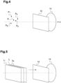
- Construction module 2 then weights the contribution c i,k,l of the light element located at point P i (contribution c i,k,l to the field as just determined) by a correction coefficient ⁇ (P i ) calculated as described below with reference to Figures 6 and 7 to take into account the fact that only a part of the user's pupil (represented by the disc ⁇ ) receives the light beam generated by the light modulator 12 (as explained below with reference to the Figure 6 ).
- the construction module 2 By performing the operations below for all pixels p k,l , the construction module 2 thus determines the values H k,l respectively associated with these pixels p k,l by summing (as explained above) the light contributions c i,k,l respectively produced by the light elements located at points P i with weighting, for each of the light contributions c i,k,l , by a correction coefficient ⁇ (P i ) depending on the point P i .
- the construction module 2 first determines the orientation of the shutter 20 (i.e. the aforementioned angle ⁇ 0 ) as a function of the distribution of the passing points (points of value 1) of the binary occultation masks O i in angular sectors defined around the optical axis Oz of the display system 10.
- S(n) which indicates the number of points of the set S' in the angular sector of index n (with n between 1 and k):
- This matrix mask ⁇ i aims to compensate for the fact that only part of the user's pupil (represented by the disc ⁇ ) receives the light beam generated by the light modulator 12 (as explained below with reference to the Figure 6 )
- ⁇ i (x,y) ⁇ (x,y,z i ) (the calculation of the correction coefficient being described below with reference to Figures 6 and 7 ).
- the light beam ⁇ is transmitted at the output of the light modulator 12 (with its central ray perpendicular to the plane of the light modulator 12), then through the converging lens 14 (with its central ray directed accordingly towards the focal point A).
- the disk ⁇ (corresponding to the user's pupil) is placed so that at least part of the light beam ⁇ crosses the disk ⁇ .
- the radius r of the disc ⁇ we use an average value generally encountered for the radius of the pupil of the human eye, for example a value between 4 mm and 8 mm, here 6 mm.
- f, d, d 1 and ⁇ are characteristics of the display system 10 presented above with reference to the Figure 2 .
- Construction module 2 can thus determine (using the formulas above) the area ⁇ of the intersection ⁇ as a function of the coordinates (x,y,z) of the point P concerned.
- This correction coefficient ⁇ (P) is inversely proportional to the proportion of the disk ⁇ (corresponding to the user's pupil) receiving the light beam ⁇ so that by weighting a light contribution received from point P by this correction coefficient ⁇ (P) as proposed above, we compensate for the fact that only this proportion of the user's pupil (represented by the disk ⁇ ) receives this light beam ⁇ .
Landscapes
- Physics & Mathematics (AREA)
- General Physics & Mathematics (AREA)
- Holo Graphy (AREA)
Claims (14)
- Verfahren zum Erzeugen eines digitalen Hologramms (H), das eine Szene darstellt und dazu bestimmt ist, mittels eines Anzeigesystems (10) angezeigt zu werden, das einen einen Lichtstrahl erzeugenden Lichtmodulator (12) und eine optische Konvergenzvorrichtung (14), die dazu ausgelegt ist, den Lichtstrahl zu einem Brennpunkt (A) konvergieren zu lassen, aufweist,wobei die Szene durch eine Gesamtheit von Leuchtelementen definiert ist,dadurch gekennzeichnet, daß es einen Schritt des Bestimmens von jeweils mit den Bildpunkten des Hologramms verbundenen Werten aufweist, indem es durch die Leuchtelemente jeweils erzeugte Leuchtbeiträge für jeden der Leuchtbeiträge mit einer Gewichtung durch einen Korrekturkoeffizienten summiert, der von der Schnittfläche (ε) einer zwischen der optischen Konvergenzvorrichtung (14) und dem Brennpunkt (A) gelegenen Oberfläche (δ) mit einem feinen Lichtstrahl (φ) mit einer vorbestimmten winkelmäßigen Öffnung (ω), der vom den betreffenden Leuchtbeitrag erzeugenden Leuchtelement aus durch die optische Konvergenzvorrichtung übertragen wird, abhängt.
- Verfahren gemäß Anspruch 1, bei dem die Leuchtelemente jeweils auf einer Anzahl Punkte (Pi) der Szene angeordnet sind und bei dem das Verfahren für jeden Punkt (Pi) der besagten Anzahl in Abhängigkeit von der Position des betreffenden Punkts einen Schritt des Berechnens des Korrekturkoeffizienten, der die vom am betreffenden Punkt (Pi) angeordneten Leuchtelement erzeugten Leuchtbeiträge wichtet, aufweist.
- Verfahren gemäß Anspruch 2, bei dem der Schritt des Bestimmens von Werten für jeden Bildpunkt des digitalen Hologramms (H) einen Schritt des Bestimmens des am betreffenden Bildpunkt durch ein an einem gegebenen Punkt (Pi) angeordnetes Leuchtelement erzeugten Felds und einen Schritt der Gewichtung des bestimmten Felds durch den für den gegebenen Punkt (Pi) berechneten Korrekturkoeffizienten aufweist.
- Verfahren gemäß Anspruch 1, bei dem die Leuchtelemente auf mindestens einer Ebene angeordnet sind.
- Verfahren gemäß Anspruch 4, bei dem der Schritt des Bestimmens von Werten einen Schritt des Ausbreitens des Leuchtfelds von einer ersten Ebene auf eine an die erste Ebene angrenzende zweite Ebene unter Anwendung einer Matrixmaske aufweist, deren Elemente jeweils den verschiedenen Punkten der ersten Ebene zugeordnet sind und einen Wert haben, der von der Schnittfläche der besagten Oberfläche mit einem feinen Lichtstrahl mit der vorbestimmten winkelmäßigen Öffnung, der vom dem betreffenden Element zugehörigen Punkt aus durch die optische Konvergenzvorrichtung übertragen wird, abhängt.
- Verfahren gemäß einem der Ansprüche 1 bis 5 mit einem Schritt des Anzeigens des erzeugten digitalen Hologramms (H) mittels des Anzeigesystems (10).
- Verfahren gemäß einem der Ansprüche 1 bis 6, bei dem das Anzeigesystem (10) eine zwischen zwei Linsen (16, 18) angeordnete Blende (20) aufweist.
- Verfahren gemäß Anspruch 7, bei dem die Ausrichtung der Blende (20) in Abhängigkeit von der Verteilung der Leuchtelemente in um die Achse (Oz) des Anzeigesystems (10) definierten Winkelbereichen bestimmt wird.
- Verfahren gemäß Anspruch 8, wobei der Anspruch 7 in Abhängigkeit vom Anspruch 3 genommen wird, bei dem das bestimmte Feld Null ist, wenn der vom am gegebenen Punkt (Pi) angeordneten Leuchtelement mit der vorbestimmten winkelmäßigen Öffnung (ω) ausgesandte Lichtstrahl (φ) von der Blende (20) vollständig erfaßt wird.
- Verfahren gemäß einem der Ansprüche 7 bis 9, bei dem die beiden Linsen (16, 18) eine identische Brennweite haben und bei dem die Blende (20) von jeder der beiden Linsen durch einen der Brennweite gleichen Abstand (F) getrennt ist.
- Verfahren gemäß einem der Ansprüche 1 bis 10, bei dem die Oberfläche (δ) eine auf die optische Achse (CLz) der optischen Konvergenzvorrichtung (14) zentrierte Scheibe ist.
- Verfahren gemäß einem der Ansprüche 1 bis 11, bei dem die vorbestimmte winkelmäßige Öffnung (ω) die winkelmäßige Öffnung des vom Lichtmodulator (12) erzeugten Lichtstrahls ist.
- Digitales holographisches System umfassend ein Modul (2) zum Erzeugen eines digitalen Hologramms (H), das eine Szene darstellt und dazu bestimmt ist, mittels eines Anzeigesystems (10) angezeigt zu werden, das einen einen Lichtstrahl erzeugenden Lichtmodulator (12) und eine optische Konvergenzvorrichtung (14), die dazu ausgelegt ist, den Lichtstrahl auf einen Brennpunkt (A) konvergieren zu lassen, aufweist, wobei die Szene durch eine Gesamtheit von Leuchtelementen definiert ist,
dadurch gekennzeichnet, daß das Erzeugungsmodul (2) dazu ausgelegt ist, jeweils Bildpunkten des digitalen Hologramms (H) zugeordnete Werte zu bestimmen, indem durch Leuchtelemente jeweils erzeugte Lichtbeiträge für jeden der Lichtbeiträge mit Gewichtung durch einen Korrekturkoeffizienten, der von der Schnittfläche (ε) einer zwischen der optischen Konvergenzvorrichtung (14) und dem Brennpunkt (A) gelegenen Oberfläche (δ) mit einem feinen Lichtstrahl (φ) mit einer vorbestimmten winkelmäßigen Öffnung (ω), der vom den betreffenden Leuchtbeitrag erzeugenden Leuchtelement aus durch die optische Konvergenzvorrichtung (14) übertragen wird, abhängt, summiert werden. - Holographisches System gemäß Anspruch 13, das außerdem das Anzeigesystem (10) aufweist.
Applications Claiming Priority (2)
| Application Number | Priority Date | Filing Date | Title |
|---|---|---|---|
| FR1903649A FR3094802B1 (fr) | 2019-04-05 | 2019-04-05 | Procédé de construction d’un hologramme numérique et système d’holographie numérique associé |
| PCT/EP2020/059007 WO2020201232A1 (fr) | 2019-04-05 | 2020-03-30 | Procédé de construction d'un hologramme numérique et système d'holographie numérique associé |
Publications (2)
| Publication Number | Publication Date |
|---|---|
| EP3948432A1 EP3948432A1 (de) | 2022-02-09 |
| EP3948432B1 true EP3948432B1 (de) | 2025-05-07 |
Family
ID=67514873
Family Applications (1)
| Application Number | Title | Priority Date | Filing Date |
|---|---|---|---|
| EP20713345.5A Active EP3948432B1 (de) | 2019-04-05 | 2020-03-30 | Verfahren zur herstellung eines digitalen hologramms und zugehöriges digitales holographisches system |
Country Status (4)
| Country | Link |
|---|---|
| US (1) | US12197171B2 (de) |
| EP (1) | EP3948432B1 (de) |
| FR (1) | FR3094802B1 (de) |
| WO (1) | WO2020201232A1 (de) |
Family Cites Families (5)
| Publication number | Priority date | Publication date | Assignee | Title |
|---|---|---|---|---|
| GB0027103D0 (en) * | 2000-11-07 | 2000-12-20 | Secr Defence | Improved 3D display |
| US7619794B2 (en) * | 2005-05-11 | 2009-11-17 | Sony Corporation | Hologram-reproducing method and hologram-reproducing device |
| GB2445164A (en) * | 2006-12-21 | 2008-07-02 | Light Blue Optics Ltd | Holographic image display systems |
| DE102007023785B4 (de) * | 2007-05-16 | 2014-06-18 | Seereal Technologies S.A. | Analytisches Verfahren zu Berechnung von Videohologrammen in Echtzeit und holographische Wiedergabeeinrichtung |
| CN106898039B (zh) * | 2017-02-23 | 2020-08-21 | 京东方科技集团股份有限公司 | 用于生成计算全息图的方法和系统 |
-
2019
- 2019-04-05 FR FR1903649A patent/FR3094802B1/fr active Active
-
2020
- 2020-03-30 US US17/601,323 patent/US12197171B2/en active Active
- 2020-03-30 WO PCT/EP2020/059007 patent/WO2020201232A1/fr not_active Ceased
- 2020-03-30 EP EP20713345.5A patent/EP3948432B1/de active Active
Also Published As
| Publication number | Publication date |
|---|---|
| FR3094802B1 (fr) | 2021-04-23 |
| WO2020201232A1 (fr) | 2020-10-08 |
| FR3094802A1 (fr) | 2020-10-09 |
| US20220187766A1 (en) | 2022-06-16 |
| EP3948432A1 (de) | 2022-02-09 |
| US12197171B2 (en) | 2025-01-14 |
Similar Documents
| Publication | Publication Date | Title |
|---|---|---|
| EP3646121B1 (de) | Verfahren zur digitalen generierung eines hologramms, vorrichtung, endgerät, zugehöriges system und computerprogramm | |
| JP7125423B2 (ja) | スキューミラー補助画像化 | |
| EP3824269B1 (de) | Verfahren und systeme zur nichtinvasiven optischen charakterisierung eines heterogenen mediums | |
| US20200225400A1 (en) | Non-uniform sub-pupil reflectors and methods in Optical Waveguides for AR, HMD and HUD applications | |
| CN115933346A (zh) | 为系统确定图像的全息图的方法 | |
| WO2019125575A1 (en) | Optical system with dispersion compensation | |
| EP2947433A1 (de) | System und verfahren zur erfassung von hyperspektralen bildern | |
| EP0394137A1 (de) | Gerät für Holographie mit inkohärentem Licht | |
| EP3994890A1 (de) | Verfahren und vorrichtung zur codierung einer digitalen hologrammsequenz | |
| CN118759732A (zh) | 光场显示方法、装置、设备及存储介质 | |
| EP3785083B1 (de) | Verfahren zur verarbeitung eines hologramms, zugehörige vorrichtung, holografisches anzeigesystem und computerprogramm | |
| FR3094802A1 (fr) | Procédé de construction d’un hologramme numérique et système d’holographie numérique associé | |
| EP4443215B1 (de) | Projektionsvorrichtung mit optimierter sendepunktverteilung aus isolinienkonfiguration | |
| FR2697351A1 (fr) | Dispositif de détermination de plan pupillaire à division de champ. | |
| EP3814850B1 (de) | Verfahren zur erzeugung eines digitalen hologramms, zugehörige vorrichtung, holographisches anzeigesystem und computerprogramm | |
| FR3069654A1 (fr) | Systeme de visualisation comportant un dispositif optique holographique permettant d'afficher des images dans des plans differents | |
| WO2017046478A1 (fr) | Procédé de traitement d'une image holographique | |
| EP2572227A1 (de) | Optisches system mit dynamischer bildkorrektur | |
| EP3545426A1 (de) | Verfahren zur schnellen simulation eines optischen systems | |
| US20230004121A1 (en) | Augmented reality holographic display using optical waveguide and holographic optical element | |
| WO2021259875A1 (fr) | Procédé et dispositif de reconstruction d'un hologramme numérique, procédé d'affichage d'un hologramme numérique et système associé | |
| FR3156214A1 (fr) | Procédé de génération d’un hologramme numérique, dispositif électronique et système associés | |
| FR3147638A1 (fr) | Dispositif de projection à répartition de points d’émission optimisée sur une surface d’émission discrétisée | |
| FR3037171A1 (fr) | Procede de determination des valeurs d'un phenomene physique dans un milieu | |
| WO2013068688A2 (fr) | Dispositif portable de vision augmentee. |
Legal Events
| Date | Code | Title | Description |
|---|---|---|---|
| STAA | Information on the status of an ep patent application or granted ep patent |
Free format text: STATUS: UNKNOWN |
|
| STAA | Information on the status of an ep patent application or granted ep patent |
Free format text: STATUS: THE INTERNATIONAL PUBLICATION HAS BEEN MADE |
|
| PUAI | Public reference made under article 153(3) epc to a published international application that has entered the european phase |
Free format text: ORIGINAL CODE: 0009012 |
|
| STAA | Information on the status of an ep patent application or granted ep patent |
Free format text: STATUS: REQUEST FOR EXAMINATION WAS MADE |
|
| 17P | Request for examination filed |
Effective date: 20211004 |
|
| AK | Designated contracting states |
Kind code of ref document: A1 Designated state(s): AL AT BE BG CH CY CZ DE DK EE ES FI FR GB GR HR HU IE IS IT LI LT LU LV MC MK MT NL NO PL PT RO RS SE SI SK SM TR |
|
| DAV | Request for validation of the european patent (deleted) | ||
| DAX | Request for extension of the european patent (deleted) | ||
| GRAP | Despatch of communication of intention to grant a patent |
Free format text: ORIGINAL CODE: EPIDOSNIGR1 |
|
| STAA | Information on the status of an ep patent application or granted ep patent |
Free format text: STATUS: GRANT OF PATENT IS INTENDED |
|
| INTG | Intention to grant announced |
Effective date: 20241216 |
|
| RAP3 | Party data changed (applicant data changed or rights of an application transferred) |
Owner name: FONDATION B-COM |
|
| GRAS | Grant fee paid |
Free format text: ORIGINAL CODE: EPIDOSNIGR3 |
|
| GRAA | (expected) grant |
Free format text: ORIGINAL CODE: 0009210 |
|
| STAA | Information on the status of an ep patent application or granted ep patent |
Free format text: STATUS: THE PATENT HAS BEEN GRANTED |
|
| AK | Designated contracting states |
Kind code of ref document: B1 Designated state(s): AL AT BE BG CH CY CZ DE DK EE ES FI FR GB GR HR HU IE IS IT LI LT LU LV MC MK MT NL NO PL PT RO RS SE SI SK SM TR |
|
| REG | Reference to a national code |
Ref country code: GB Ref legal event code: FG4D Free format text: NOT ENGLISH |
|
| REG | Reference to a national code |
Ref country code: CH Ref legal event code: EP |
|
| REG | Reference to a national code |
Ref country code: DE Ref legal event code: R096 Ref document number: 602020050784 Country of ref document: DE |
|
| REG | Reference to a national code |
Ref country code: IE Ref legal event code: FG4D Free format text: LANGUAGE OF EP DOCUMENT: FRENCH |
|
| REG | Reference to a national code |
Ref country code: NL Ref legal event code: MP Effective date: 20250507 |
|
| PG25 | Lapsed in a contracting state [announced via postgrant information from national office to epo] |
Ref country code: PT Free format text: LAPSE BECAUSE OF FAILURE TO SUBMIT A TRANSLATION OF THE DESCRIPTION OR TO PAY THE FEE WITHIN THE PRESCRIBED TIME-LIMIT Effective date: 20250908 Ref country code: FI Free format text: LAPSE BECAUSE OF FAILURE TO SUBMIT A TRANSLATION OF THE DESCRIPTION OR TO PAY THE FEE WITHIN THE PRESCRIBED TIME-LIMIT Effective date: 20250507 Ref country code: ES Free format text: LAPSE BECAUSE OF FAILURE TO SUBMIT A TRANSLATION OF THE DESCRIPTION OR TO PAY THE FEE WITHIN THE PRESCRIBED TIME-LIMIT Effective date: 20250507 |
|
| REG | Reference to a national code |
Ref country code: LT Ref legal event code: MG9D |
|
| PG25 | Lapsed in a contracting state [announced via postgrant information from national office to epo] |
Ref country code: NO Free format text: LAPSE BECAUSE OF FAILURE TO SUBMIT A TRANSLATION OF THE DESCRIPTION OR TO PAY THE FEE WITHIN THE PRESCRIBED TIME-LIMIT Effective date: 20250807 Ref country code: GR Free format text: LAPSE BECAUSE OF FAILURE TO SUBMIT A TRANSLATION OF THE DESCRIPTION OR TO PAY THE FEE WITHIN THE PRESCRIBED TIME-LIMIT Effective date: 20250808 |
|
| PG25 | Lapsed in a contracting state [announced via postgrant information from national office to epo] |
Ref country code: NL Free format text: LAPSE BECAUSE OF FAILURE TO SUBMIT A TRANSLATION OF THE DESCRIPTION OR TO PAY THE FEE WITHIN THE PRESCRIBED TIME-LIMIT Effective date: 20250507 Ref country code: PL Free format text: LAPSE BECAUSE OF FAILURE TO SUBMIT A TRANSLATION OF THE DESCRIPTION OR TO PAY THE FEE WITHIN THE PRESCRIBED TIME-LIMIT Effective date: 20250507 |
|
| REG | Reference to a national code |
Ref country code: AT Ref legal event code: MK05 Ref document number: 1793134 Country of ref document: AT Kind code of ref document: T Effective date: 20250507 |
|
| PG25 | Lapsed in a contracting state [announced via postgrant information from national office to epo] |
Ref country code: BG Free format text: LAPSE BECAUSE OF FAILURE TO SUBMIT A TRANSLATION OF THE DESCRIPTION OR TO PAY THE FEE WITHIN THE PRESCRIBED TIME-LIMIT Effective date: 20250507 |
|
| PG25 | Lapsed in a contracting state [announced via postgrant information from national office to epo] |
Ref country code: HR Free format text: LAPSE BECAUSE OF FAILURE TO SUBMIT A TRANSLATION OF THE DESCRIPTION OR TO PAY THE FEE WITHIN THE PRESCRIBED TIME-LIMIT Effective date: 20250507 |
|
| PG25 | Lapsed in a contracting state [announced via postgrant information from national office to epo] |
Ref country code: AT Free format text: LAPSE BECAUSE OF FAILURE TO SUBMIT A TRANSLATION OF THE DESCRIPTION OR TO PAY THE FEE WITHIN THE PRESCRIBED TIME-LIMIT Effective date: 20250507 |
|
| PG25 | Lapsed in a contracting state [announced via postgrant information from national office to epo] |
Ref country code: RS Free format text: LAPSE BECAUSE OF FAILURE TO SUBMIT A TRANSLATION OF THE DESCRIPTION OR TO PAY THE FEE WITHIN THE PRESCRIBED TIME-LIMIT Effective date: 20250807 |
|
| PG25 | Lapsed in a contracting state [announced via postgrant information from national office to epo] |
Ref country code: IS Free format text: LAPSE BECAUSE OF FAILURE TO SUBMIT A TRANSLATION OF THE DESCRIPTION OR TO PAY THE FEE WITHIN THE PRESCRIBED TIME-LIMIT Effective date: 20250907 |
|
| PG25 | Lapsed in a contracting state [announced via postgrant information from national office to epo] |
Ref country code: LV Free format text: LAPSE BECAUSE OF FAILURE TO SUBMIT A TRANSLATION OF THE DESCRIPTION OR TO PAY THE FEE WITHIN THE PRESCRIBED TIME-LIMIT Effective date: 20250507 |
|
| PG25 | Lapsed in a contracting state [announced via postgrant information from national office to epo] |
Ref country code: DK Free format text: LAPSE BECAUSE OF FAILURE TO SUBMIT A TRANSLATION OF THE DESCRIPTION OR TO PAY THE FEE WITHIN THE PRESCRIBED TIME-LIMIT Effective date: 20250507 Ref country code: SM Free format text: LAPSE BECAUSE OF FAILURE TO SUBMIT A TRANSLATION OF THE DESCRIPTION OR TO PAY THE FEE WITHIN THE PRESCRIBED TIME-LIMIT Effective date: 20250507 |
|
| PG25 | Lapsed in a contracting state [announced via postgrant information from national office to epo] |
Ref country code: CZ Free format text: LAPSE BECAUSE OF FAILURE TO SUBMIT A TRANSLATION OF THE DESCRIPTION OR TO PAY THE FEE WITHIN THE PRESCRIBED TIME-LIMIT Effective date: 20250507 |
|
| PG25 | Lapsed in a contracting state [announced via postgrant information from national office to epo] |
Ref country code: EE Free format text: LAPSE BECAUSE OF FAILURE TO SUBMIT A TRANSLATION OF THE DESCRIPTION OR TO PAY THE FEE WITHIN THE PRESCRIBED TIME-LIMIT Effective date: 20250507 |
|
| PG25 | Lapsed in a contracting state [announced via postgrant information from national office to epo] |
Ref country code: SK Free format text: LAPSE BECAUSE OF FAILURE TO SUBMIT A TRANSLATION OF THE DESCRIPTION OR TO PAY THE FEE WITHIN THE PRESCRIBED TIME-LIMIT Effective date: 20250507 Ref country code: RO Free format text: LAPSE BECAUSE OF FAILURE TO SUBMIT A TRANSLATION OF THE DESCRIPTION OR TO PAY THE FEE WITHIN THE PRESCRIBED TIME-LIMIT Effective date: 20250507 |
|
| PG25 | Lapsed in a contracting state [announced via postgrant information from national office to epo] |
Ref country code: IT Free format text: LAPSE BECAUSE OF FAILURE TO SUBMIT A TRANSLATION OF THE DESCRIPTION OR TO PAY THE FEE WITHIN THE PRESCRIBED TIME-LIMIT Effective date: 20250507 |
|
| REG | Reference to a national code |
Ref country code: DE Ref legal event code: R097 Ref document number: 602020050784 Country of ref document: DE |
|
| PLBE | No opposition filed within time limit |
Free format text: ORIGINAL CODE: 0009261 |
|
| STAA | Information on the status of an ep patent application or granted ep patent |
Free format text: STATUS: NO OPPOSITION FILED WITHIN TIME LIMIT |
|
| REG | Reference to a national code |
Ref country code: CH Ref legal event code: L10 Free format text: ST27 STATUS EVENT CODE: U-0-0-L10-L00 (AS PROVIDED BY THE NATIONAL OFFICE) Effective date: 20260318 |
|
| 26N | No opposition filed |
Effective date: 20260210 |