EP3948250B1 - Verfahren zur diagnose von abgassensoren - Google Patents
Verfahren zur diagnose von abgassensoren Download PDFInfo
- Publication number
- EP3948250B1 EP3948250B1 EP20714520.2A EP20714520A EP3948250B1 EP 3948250 B1 EP3948250 B1 EP 3948250B1 EP 20714520 A EP20714520 A EP 20714520A EP 3948250 B1 EP3948250 B1 EP 3948250B1
- Authority
- EP
- European Patent Office
- Prior art keywords
- swt
- short
- ipe
- mes
- potential
- Prior art date
- Legal status (The legal status is an assumption and is not a legal conclusion. Google has not performed a legal analysis and makes no representation as to the accuracy of the status listed.)
- Active
Links
Images





Classifications
-
- G—PHYSICS
- G01—MEASURING; TESTING
- G01M—TESTING STATIC OR DYNAMIC BALANCE OF MACHINES OR STRUCTURES; TESTING OF STRUCTURES OR APPARATUS, NOT OTHERWISE PROVIDED FOR
- G01M15/00—Testing of engines
- G01M15/04—Testing internal-combustion engines
- G01M15/10—Testing internal-combustion engines by monitoring exhaust gases or combustion flame
- G01M15/102—Testing internal-combustion engines by monitoring exhaust gases or combustion flame by monitoring exhaust gases
- G01M15/104—Testing internal-combustion engines by monitoring exhaust gases or combustion flame by monitoring exhaust gases using oxygen or lambda-sensors
-
- G—PHYSICS
- G01—MEASURING; TESTING
- G01N—INVESTIGATING OR ANALYSING MATERIALS BY DETERMINING THEIR CHEMICAL OR PHYSICAL PROPERTIES
- G01N27/00—Investigating or analysing materials by the use of electric, electrochemical, or magnetic means
- G01N27/26—Investigating or analysing materials by the use of electric, electrochemical, or magnetic means by investigating electrochemical variables; by using electrolysis or electrophoresis
- G01N27/403—Cells and electrode assemblies
- G01N27/406—Cells and probes with solid electrolytes
- G01N27/4065—Circuit arrangements specially adapted therefor
-
- G—PHYSICS
- G01—MEASURING; TESTING
- G01N—INVESTIGATING OR ANALYSING MATERIALS BY DETERMINING THEIR CHEMICAL OR PHYSICAL PROPERTIES
- G01N27/00—Investigating or analysing materials by the use of electric, electrochemical, or magnetic means
- G01N27/26—Investigating or analysing materials by the use of electric, electrochemical, or magnetic means by investigating electrochemical variables; by using electrolysis or electrophoresis
- G01N27/416—Systems
- G01N27/4163—Systems checking the operation of, or calibrating, the measuring apparatus
-
- G—PHYSICS
- G01—MEASURING; TESTING
- G01N—INVESTIGATING OR ANALYSING MATERIALS BY DETERMINING THEIR CHEMICAL OR PHYSICAL PROPERTIES
- G01N27/00—Investigating or analysing materials by the use of electric, electrochemical, or magnetic means
- G01N27/26—Investigating or analysing materials by the use of electric, electrochemical, or magnetic means by investigating electrochemical variables; by using electrolysis or electrophoresis
- G01N27/416—Systems
- G01N27/417—Systems using cells, i.e. more than one cell and probes with solid electrolytes
- G01N27/4175—Calibrating or checking the analyser
-
- G—PHYSICS
- G01—MEASURING; TESTING
- G01R—MEASURING ELECTRIC VARIABLES; MEASURING MAGNETIC VARIABLES
- G01R31/00—Arrangements for testing electric properties; Arrangements for locating electric faults; Arrangements for electrical testing characterised by what is being tested not provided for elsewhere
- G01R31/50—Testing of electric apparatus, lines, cables or components for short-circuits, continuity, leakage current or incorrect line connections
- G01R31/58—Testing of lines, cables or conductors
-
- H—ELECTRICITY
- H02—GENERATION; CONVERSION OR DISTRIBUTION OF ELECTRIC POWER
- H02H—EMERGENCY PROTECTIVE CIRCUIT ARRANGEMENTS
- H02H3/00—Emergency protective circuit arrangements for automatic disconnection directly responsive to an undesired change from normal electric working condition with or without subsequent reconnection ; integrated protection
-
- H—ELECTRICITY
- H02—GENERATION; CONVERSION OR DISTRIBUTION OF ELECTRIC POWER
- H02H—EMERGENCY PROTECTIVE CIRCUIT ARRANGEMENTS
- H02H3/00—Emergency protective circuit arrangements for automatic disconnection directly responsive to an undesired change from normal electric working condition with or without subsequent reconnection ; integrated protection
- H02H3/02—Details
- H02H3/021—Details concerning the disconnection itself, e.g. at a particular instant, particularly at zero value of current, disconnection in a predetermined order
- H02H3/023—Details concerning the disconnection itself, e.g. at a particular instant, particularly at zero value of current, disconnection in a predetermined order by short-circuiting
-
- H—ELECTRICITY
- H02—GENERATION; CONVERSION OR DISTRIBUTION OF ELECTRIC POWER
- H02H—EMERGENCY PROTECTIVE CIRCUIT ARRANGEMENTS
- H02H3/00—Emergency protective circuit arrangements for automatic disconnection directly responsive to an undesired change from normal electric working condition with or without subsequent reconnection ; integrated protection
- H02H3/20—Emergency protective circuit arrangements for automatic disconnection directly responsive to an undesired change from normal electric working condition with or without subsequent reconnection ; integrated protection responsive to excess voltage
Definitions
- An evaluation and control unit is already known that is designed as an ASIC. It is used to operate a broadband lambda sensor that has electrical lines, the evaluation and control unit having electrical connections for electrical connection to the electrical lines of the broadband lambda sensor and the electrical connections are each assigned an electrical switch via which the respective connection is connected to ground is connectable.
- Another evaluation and control unit is from the DE 10 2011 077 171 A1 known.
- the present invention is based on the inventors' consideration that the switches already known from the prior art mentioned can be exposed to high electrical loads in the event of a fault. For example, in the event of a short circuit in a line of the lambda sensor with a supply voltage, the switches can be exposed to the full supply voltage and the resulting currents. In the event of a fault, the maximum short-circuit voltage to be expected at the respective connection can in this case be given by the supply voltage.
- the value of the voltage which is referred to here as the maximum short-circuit voltage to be expected in the event of a fault at the respective connection, is 16V.
- the respective switch is voltage-proof against the maximum short-circuit voltage to be expected at the respective connection in the event of a fault .
- the dielectric strength of a component against a voltage is understood here as the property of the component that it can be exposed to this voltage for several seconds without causing damage.
- this requires appropriate design measures, for example sufficient insulation and/or shielding.
- the respective switch is designed as a low-resistance switch, i.e. in the closed state it has in particular a contact resistance that is not greater than the internal resistance of the electrochemical cells of the broadband lambda probe at operating temperature and / or in particular has a volume resistance that is not greater than 100 ohms.
- each switch can be individually connected to an electrical potential, which can assume two different defined values.
- One of the defined electrical potentials can be the ground potential, for example 0V, or a virtual ground that is at a different potential. It is further provided that different potentials are made available through appropriate voltage sources and/or corresponding voltage dividers.
- a voltage divider is provided between the respective switch and the defined electrical potential, through which, in the event of a fault, a partial voltage of the maximum expected short-circuit voltage can be tapped, which is within the measuring range of a measuring system, for example an ADC, the evaluation and Control unit is located.
- a targeted diagnosis of the broadband lambda sensor can be carried out in the event of a fault.
- the measuring range of the measuring system for example the ADC
- the evaluation and Control unit can be, for example, 0V - 3.6V or -5V - +5V.
- the voltage divider can, for example, divide the maximum expected short-circuit voltage down to the upper limit of the measuring range of the measuring system.
- a voltage divider can be provided, for example, which divides the applied voltage in a ratio of 9 to 1.
- a single voltage divider can be provided which is connected to all switches.
- each switch can be assigned an individual voltage divider.
- connections can be connected to one another via the switches, in particular can be short-circuited.
- the broadband lambda sensor leads can then be placed at a common electrical potential, thereby protecting the broadband lambda sensor, especially if the switches are only opened for diagnostic purposes and otherwise remain closed.
- a further switch is also arranged between the switches and the defined electrical potential, this can be opened in the event of a fault, so that a current flow through the broadband lambda probe to the defined electrical potential then ceases.
- ohmic resistors are connected in series between the respective switch and the defined electrical potential.
- the ratio of the resistance values of the ohmic resistors determines the ratio in which the voltage applied to the voltage divider is divided.
- ohmic resistors 3.24 kOhm and 360 Ohm can be selected, for example, if a maximum of 10mA should flow.
- the The ohmic resistance of the voltage divider facing the switch is voltage-proof against the maximum short-circuit voltage expected at the connections in the event of a fault.
- the dielectric strength of the ohmic resistance of the voltage divider facing away from the switch does not exceed the dielectric strength of the measuring system.
- the method according to the invention takes place with an evaluation and control unit in which the defined electrical potential can assume two different defined values. It is envisaged that for each connection line a first current is measured while the defined potential has a first value, and a second current is measured while the defined potential has a second value.
- the various defined values of the defined electrical potential can be generated, for example, via adjustable voltage dividers.
- R SC R ref * I 1 ⁇ I 2 ⁇ I 0.1 + I 0.2 + v SET ,1 ⁇ v SET , 2 / I 2 ⁇ I 1 ⁇ I 0.2 + I 0.1 .
- Vsc 1 / 2 * R SC * I 1 + I 2 + I 0.1 + I 0.2 + R ref * I 1 + I 2 + v SET ,1 + v SET , 2 .
- a short-circuit resistance and a short-circuit voltage can be determined for each connecting cable by calculation. If the electrical lines of the lambda probe are not high-resistance to each other but the internal resistances of the lambda probe are still known or certain values are assumed, the calculation of the short-circuit resistances and the calculation of the short-circuit voltages is carried out by solving the resulting linear systems of equations.
- a short circuit is concluded when at least one determined short circuit resistance falls below a predetermined threshold value and the short circuit is assigned to the line that is connected to the connection at which the smallest short circuit resistance occurred.
- the measurements are repeated after a waiting time in which the broadband lambda sensor cools down.
- the broadband lambda sensor cools down.
- the information about the existence of a short circuit in particular the fact of a short circuit itself, the line on which the short circuit was detected, the short circuit potential and/or the short circuit resistance; are stored in a non-volatile data memory, for example by an entry in an error memory of the evaluation and control unit and / or in an error memory of a control device connected to the evaluation and control unit.
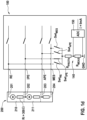
- the Figure 1a shows an evaluation and control unit 100 for operating a broadband lambda probe 200 (not an exemplary embodiment according to the invention).
- the evaluation and control unit 100 is connected to electrical lines 201, 202, 203, 204 of a broadband lambda probe 200 via four connections RE, IPE, APE, MES. These lines lead to electrochemical cells 210, 211 of the broadband lambda probe 200. Possible details of the broadband lambda probe 200 are, for example, in the DE 10 2011 007 068 A1 shown.
- the evaluation and control unit 100 is only shown to the extent necessary for understanding the present invention. Possible details of the evaluation and control unit 100 are, for example, in the patent specification EP 2 277 035 B1 shown.
- the evaluation and control unit 100 has a connection to ground GND, with which each of the connections RE, IPE, APE, MES individually has a voltage-proof switch Swt RE , Swt IPE , Swt APE , Swt MES and a common voltage divider 140 is connected.
- the voltage U dropping across the resistor R_Meas can be measured by an ADC 150 of the evaluation and control unit 100. Dividing with R_Meas results in the current I flowing through the voltage divider 140.
- another switch can be provided between the resistor R_Meas and GND (in the Figure 1a not drawn). If it is opened in the event of a fault, this means that current does not flow through the broadband lambda sensor 200 to GND.
- connection RE The highest current I was clearly determined for the connection RE. Since it was known in advance that there was an impermissibly high potential at this 36V connection, i.e. it was known that a short circuit basically existed, it is concluded that the short circuit is present on the line 201 of the broadband lambda sensor 200 connected to the connection RE.
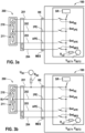
- the Figure 3a shows an exemplary embodiment according to the invention of an evaluation and control unit 100 for operating a broadband lambda probe 200.
- the evaluation and control unit 100 is connected to a broadband lambda probe 200 via four connections RE, IPE, APE, MES with electrical lines 201, 202, 203, 204 connected, which is so cold that there is a very high internal resistance R i between any two of the lines 201, 202, 203, 204, for example 1 MOhm.
- These lines lead to electrochemical cells 210, 211 of the broadband lambda probe 200.
- Possible details of the broadband lambda probe 200 are, for example, in the DE 10 2011 007 068 A1 shown.
- the evaluation and control unit 100 is only shown to the extent necessary for understanding the present invention. Possible details of the evaluation and control unit 100 are, for example, in the patent specification EP 2 277 035 B1 shown.
- a power source SR can be connected on the side of the switches Swt RE , Swt IPE , Swt APE, Swt MES facing away from the connections RE, IPE, APE , MES. In the example, however, it is separated by an open switch.
- R SC R ref * I 1 ⁇ I 2 ⁇ I 0.1 + I 0.2 + v SET ,1 ⁇ v SET , 2 / I 2 ⁇ I 1 ⁇ I 0.2 + I 0.1
Landscapes
- Chemical & Material Sciences (AREA)
- Health & Medical Sciences (AREA)
- Life Sciences & Earth Sciences (AREA)
- Physics & Mathematics (AREA)
- General Physics & Mathematics (AREA)
- Biochemistry (AREA)
- Electrochemistry (AREA)
- Analytical Chemistry (AREA)
- Chemical Kinetics & Catalysis (AREA)
- General Health & Medical Sciences (AREA)
- Molecular Biology (AREA)
- Immunology (AREA)
- Pathology (AREA)
- Engineering & Computer Science (AREA)
- Combustion & Propulsion (AREA)
- Emergency Medicine (AREA)
- Testing Of Short-Circuits, Discontinuities, Leakage, Or Incorrect Line Connections (AREA)
Description
- Aus der
DE 10 2010 000 663 A1 ist bereits eine Auswerte- und Steuereinheit bekannt, die als ASIC ausgebildet ist. Sie dient dem Betrieb einer Breitband-Lambdasonde, die elektrische Leitungen aufweist, wobei die Auswerte- und Steuereinheit elektrische Anschlüsse zur elektrischen Verbindung mit den elektrischen Leitungen der Breitbandlambdasonde aufweist und den elektrischen Anschlüssen jeweils ein elektrischer Schalter zugeordnet ist, über den der jeweilige Anschluss mit Masse verbindbar ist. - Eine weitere Auswerte- und Steuereinheit ist aus der
DE 10 2011 077 171 A1 bekannt. - Die vorliegende Erfindung beruht auf der Überlegung der Erfinder, dass die aus dem genannten Stand der Technik grundsätzlich bereits bekannten Schalter im Fehlerfall hohen elektrischen Belastungen ausgesetzt sein können. Beispielsweise können die Schalter im Fall eines Kurzschlusses einer Leitung der Lambdasonde mit einer Versorgungsspannung der vollen Versorgungsspannung und den daraus resultierenden Strömen ausgesetzt sein. Die im Fehlerfall an dem jeweiligen Anschluss maximal zu erwartende Kurzschluss-Spannung kann in diesem Fall durch die Versorgungsspannung gegeben sein.
- Der Wert der Spannung, die hier als die im Fehlerfall an dem jeweiligen Anschluss maximal zu erwartende Kurzschluss-Spannung bezeichnet wird, beträgt 16V.
- Um ohne weitere hardware- oder softwareseitigen Schutzmechanismen sicherzustellen, dass in derartigen Fehlerfällen an den Leitungen der Breitbandlambda-Sonde keine Schäden der Auswerte- und Steuereinheit resultieren, und um überdies auch im Fehlerfall ein Verfahren zur Diagnose der elektrischen Leitungen einer Breitbandlambdasonde zu ermöglichen, ist insbesondere vorgesehen, dass der jeweilige Schalter spannungsfest gegen die im Fehlerfall an dem jeweiligen Anschluss maximal zu erwartende Kurzschluss-Spannung ist.
- Unter der Spannungsfestigkeit eines Bauteils gegen eine Spannung wird hier die Eigenschaft des Bauteils verstanden, dieser Spannung über mehrere Sekunden, ohne Schädigung aussetzbar zu sein. Insbesondere bei hoher Miniaturisierung, beispielsweise bei Ausführung des Bauteils als Teil einer als ASIC ausgeführten Auswerte- und Steuereinheit, setzt dies entsprechende konstruktive Maßnahmen voraus, beispielsweise ausreichende Isolierungen und/oder Abschirmungen.
- Um im Fehlerfall die gewünschten Diagnosen durchführen zu können, ist es bevorzugt, dass der jeweilige Schalter als niederohmiger Schalter ausgeführt ist, also im geschlossenen Zustand insbesondere einen Durchgangswiderstand hat, der nicht größer ist als der Innenwiderstand der elektrochemischen Zellen der Breitband-Lambdasonde bei Betriebstemperatur und/oder insbesondere einen Durchgangswiderstand hat, der nicht größer ist als 100 Ohm.
- Erfindungsgemäß ist es vorgesehen, dass jeder Schalter individuell mit einem elektrischen Potential verbindbar ist, welches zwei verschiedene definierte Werte annehmen kann. Eines der definierten elektrischen Potentiale kann das Massenpotential, beispielsweise 0V, sein, oder eine virtuelle Masse, die auf einem anderen Potential liegt. Es ist weiter vorgesehen, dass durch entsprechende Spannungsquellen und/oder entsprechende Spannungsteiler verschiedene Potenziale zu Verfügung gestellt werden.
- Insbesondere ist vorgesehen, dass zwischen dem jeweiligen Schalter und dem definierten elektrischen Potenzial ein Spannungsteiler vorgesehen ist, durch den im Fehlerfall eine Teilspannung der maximal zu erwartenden Kurzschluss-Spannung abgreifbar ist, die innerhalb des Messbereichs eines Messsystems, beispielsweise eines ADCs, der Auswerte- und Steuereinheit liegt. Auf diese Weise kann eine gezielte Diagnose der Breitband-Lambdasonde im Fehlerfall vorgenommen werden.
- Der Messbereich des Messsystems, beispielsweise des ADCs, der Auswerte- und Steuereinheit kann beispielsweise 0V - 3,6V oder beispielsweise -5V - +5 V betragen.
- Der Spannungsteiler kann also beispielsweise die maximal zu erwartende Kurzschluss-Spannung auf die obere Grenze des Messbereichs des Messsystems herunterteilen. Bei einer maximal zu erwartenden Kurzschluss-Spannung von 36V und einer oberen Grenze des Messbereichs des Messsystems von 3,6V kann also beispielsweise ein Spannungsteiler vorgesehen werden, der die anliegende Spannung im Verhältnis 9 zu 1 teilt.
- Vorteilhafterweise kann ein einziger Spannungsteiler vorgesehen sein, der mit sämtlichen Schaltern verbunden ist. Alternativ kann jedem Schalter ein individueller Spannungsteiler zugeordnet sein.
- Es ist vorteilhaft, wenn die Anschlüsse über die Schalter miteinander verbindbar, insbesondere kurzschließbar sind. Die Leitungen der Breitband-Lambdasonde können dann auf ein gemeinsames elektrisches Potenzial gelegt werden, wodurch die Breitbandlambdasonde geschützt wird, insbesondere wenn die Schalter nur noch zum Zwecke der Diagnose geöffnet werden und ansonsten geschlossen bleiben.
- Ist ferner zwischen den Schaltern und dem definierten elektrischen Potenzial ein weiterer Schalter angeordnet, kann dieser im Fehlerfall geöffnet werden, sodass ein Stromfluss durch die Breitbandlambdasonde zu dem definierten elektrischen Potenzial dann unterbleibt.
- Es kann vorgehen sein, dass zur Realisierung des Spannungsteilers zwei ohmsche Widerstände zwischen dem jeweiligen Schalter und dem definierten elektrischen Potenzial in Reihe geschaltet sind. Das Verhältnis der Widerstandswerte der ohmschen Widerstände bestimmt dann das Verhältnis, in dem die am Spannungsteiler anliegende Spannung geteilt wird. Bei einer maximal zu erwartenden Kurzschluss-Spannung von 36V gegen das definierte elektrische Potenzial und einer oberen Grenze des Messbereichs des Messsystems von 3,6V gegen das definierte Potenzial können also beispielsweise ohmsche Widerstände von 3,24 kOhm und 360 Ohm gewählt werden, wenn maximal 10mA fließen sollen.
- In einer sehr bevorzugten Weiterbildung der Erfindung ist vorgesehen, dass auch der dem Schalter zugewandte ohmsche Widerstand des Spannungsteilers spannungsfest gegen die im Fehlerfall an den Anschlüssen maximal zu erwartende Kurzschluss-Spannung ist.
- Dabei kann vorgesehen sein, dass die Spannungsfestigkeit des von dem Schalter abgewandten ohmschen Widerstands des Spannungsteilers nicht über die Spannungsfestigkeit des Messsystems hinausgeht.
- Das erfindungsgemäße Verfahren erfolgt mit einer Auswerte- und Steuereinheit, bei der das definierte elektrische Potenzial zwei verschiedene definierte Werte annehmen kann. Es ist dabei vorgesehen, dass für jede Anschlussleitung ein erster Strom gemessen wird, während das definierte Potenzial einen ersten Wert hat, und ein zweiter Strom gemessen wird, während das definierte Potenzial einen zweiten Wert hat.
- Die verschiedenen definierten Werte des definierten elektrischen Potenzials können beispielsweise über einstellbare Spannungsteiler generiert werden.
- Gemäß der Annahme, dass die elektrischen Verbindungen der Lambdasonde zueinander hochohmig sind, erfolgt die Rechnung gemäß der Formel:

- Dabei ist:
- RSC:
- der Kurzschlusswiderstand,
- Rref:
- der Gesamtwiderstand zwischen definiertem Potenzial und dem Schalter,
- I1, I2:
- der dem Anschluss zugeordnete Strom bei Anliegen des ersten bzw. zweiten Potenzials bei geschlossenem Schalter,
- I01, I02:
- der dem Anschluss zugeordnete Strom bei Anliegen des ersten bzw. zweiten Potenzials bei offenem Schalter,
- VSET1, VSET2:
- das erste bzw. zweite Potenzial.
- Unter der Annahme, dass die elektrischen Leitungen der Lambdasonde zueinander hochohmig sind, erfolgt die Rechnung gemäß der Formel:

- Dabei ist:
- VSC:
- die Kurzschlussspannung.
- Es kann grundsätzlich für jede Anschlussleitung ein Kurzschlusswiderstand und eine Kurzschlussspannung durch Rechnung bestimmt werden. Sind die elektrischen Leitungen der Lambdasonde zueinander nicht hochohmig aber sind die Innenwiderstände der Lambdasonde dennoch bekannt oder werden bestimmte Werte angenommen, erfolgt die Berechnung der Kurzschlusswiderstände und die Berechnung der Kurzschlussspannungen durch Lösen der sich ergebenden linearen Gleichungssysteme.
- Vorteilhafterweise ist vorgesehen, dass auf einen Kurzschluss geschlossen wird, wenn zumindest ein ermittelter Kurzschlusswiderstand einen vorgegebenen Schwellwert unterschreitet und der Kurzschluss der Leitung zugeordnet wird, die mit dem Anschluss verbunden ist, an dem der kleinste Kurzschlusswiderstand aufgetreten ist.
- Es kann vorgesehen sein, dass in dem Fall, in dem der kleinste Kurzschlusswiderstand nicht mehr als ein additiver oder multiplikativer Schwellwert von dem zweitkleinsten Kurzschlusswiderstand verschieden ist, die Messungen nach einer Wartezeit, in der die Breitband-Lambdasonde sich abkühlt, wiederholt wird. Durch die Abkühlung kann erwartet werden, dass der Kurzschlusswiderstand an den Leitungen, an denen kein Kurzschluss vorliegt, zunimmt. Dann kann eindeutig bestimmt werden, an welcher Leitung der Kurzschluss tatsächlich vorliegt.
- Aus der Kenntnis des Diagnoseergebnisses können geeignete technische Maßnahmen abgeleitet werden. Beispielsweise kann vorgesehen sein, dass die Information über das Vorliegen eines Kurzschlusses; insbesondere die Tatsache eines Kurzschlusses an sich, die Leitung an der der Kurzschluss festgestellt wurde, das Kurzschlusspotenzial und/oder der Kurzschlusswiderstand; in einem nichtflüchtigen Datenspeicher abgelegt werden, beispielsweise durch einen Eintrag in einem Fehlerspeicher der Auswerte- und Steuereinheit und/oder in einem Fehlerspeicher eines mit der Auswerte- und Steuereinheit verbundenen Steuergeräts.
- Zeichnung
- Figur 1
- zeigt eine Auswerte- und Steuereinheit zum Betreiben einer Breitband-Lambdasonde (kein erfindungsgemäßes Ausführbeispiel)..
- Figur 2
- zeigt ein Flussdiagramm eines Diagnoseverfahrens mit der Auswerte- und Steuereinheit gemäß
Figur 1 . - Figur 3
- zeigt ein erfindungsgemäßes Ausführungsbeispiel einer Auswerte- und Steuereinheit zum Betreiben einer Breitband-Lambdasonde.
- Figur 4
- zeigt ein Flussdiagramm eines Diagnoseverfahrens mit der Auswerte- und Steuereinheit gemäß
Figur 3 . - Die
Figur 1a zeigt eine Auswerte- und Steuereinheit 100 zum Betreiben einer Breitband-Lambdasonde 200 (kein erfindungsgemäßes Ausführbeispiel). Die Auswerte- und Steuereinheit 100 ist über vier Anschlüsse RE, IPE, APE, MES mit elektrischen Leitungen 201, 202, 203, 204 einer Breitband-Lambdasonde 200 verbunden. Diese Leitungen führen zu elektrochemischen Zellen 210, 211 der Breitband-Lambdasonde 200. Mögliche Details der Breitband-Lambdasonde 200 sind beispielsweise in derDE 10 2011 007 068 A1 dargestellt. - Die Auswerte- und Steuereinheit 100 ist nur insofern gezeigt, wie es für das Verständnis der vorliegenden Erfindung erforderlich ist. Mögliche Details der Auswerte- und Steuereinheit 100 sind beispielsweise in der Patentschrift
EP 2 277 035 B1 dargestellt. - Die Auswerte- und Steuereinheit 100 verfügt im Beispiel über einen Anschluss an Masse GND, mit dem jeder der Anschlüsse RE, IPE, APE, MES individuell über jeweils einen spannungsfesten Schalter SwtRE, SwtIPE, SwtAPE, SwtMES und über einen gemeinsamen Spannungsteiler 140 verbunden ist.
- Der gemeinsame Spannungsteiler 140 besteht im Beispiel aus zwei in Reihe geschalteten ohmschen Widerständen R_Protn und R_Meas. Ihre Widerstandswerte betragen in diesem Beispiel R_Protn = 3,24 kOhm und R_Meas = 360 Ohm.
- Die über dem Widerstand R_Meas abfallende Spannung U ist durch einen ADC 150 der Auswerte- und Steuereinheit 100 messbar. Durch Division mit R_Meas ergibt sich der durch den Spannungsteiler 140 fließende Strom I.
- Beispielsweise zwischen dem Widerstand R_Meas und GND kann ein weiterer Schalter vorgesehen sein (in der
Figur 1a nicht gezeichnet). Wird er im Fehlerfall geöffnet, bewirkt dies, dass ein Stromfluss durch die Breitbandlambdasonde 200 nach GND unterbleibt. - In der
Figur 1b ist der Fehlerfall eines niederohmigen Kurzschlusses der Leitung 201 an eine Versorgungsspannung von 36 V gezeigt, indem über die Leitung 201 der Breitband-Lambdasonde 200 an dem Anschluss RE der Auswerte- und Steuereinheit 100 die Kurzschlussspannung U_SC = 36V über den Kurzschlusswiderstand R_SC = 0 Ohm dargestellt ist. - In der
Figur 1c wurde der dem Anschluss RE zugeordnete niederohmige Schalter SwtRE (Innenwiderstand RSwtRE = 100 Ohm) geschlossen, sodass ein Strom I von 9,7 mA von der Leitung 201 über den Anschluss RE und den Spannungsteiler 140 zur Masse GND fließt. Am Messwiderstand R_Meas fällt folglich eine Spannung von 3,502 V ab, die durch den ADC 150 digitalisiert wird. - In der
Figur 1d wurde der dem Anschluss RE zugeordnete niederohmige Schalter SwtRE geöffnet und stattdessen der dem Anschluss IPE zugeordnete niederohmige Schalter SwtIPE (Innenwiderstand RSwtIPE = 100 Ohm) geschlossen. Da der Innenwiderstand der Breitband-Lambdasonde zwischen den Leitungen 201 und 202 im heißen Zustand Ri = 300 Ohm beträgt, fließt nun ein Strom I über den Spannungsteiler 140 zur Masse GND, der 9 mA beträgt. Entsprechend fällt am Messwiderstand R_Meas eine Spannung von 3,240 V ab, die durch den ADC 150 digitalisiert wird. - Ähnliche Ströme und Spannungen ergeben sich, wenn anstelle des Schalters SwtIPE der Schalter SwtAPE geschlossen wird oder wenn der Schalter SwtMES geschlossen wird.
- Für den Anschluss RE wurde eindeutig der höchste Strom I ermittelt. Da vorab bekannt war, dass an diesem Anschluss mit 36V ein unzulässig hohes Potenzial anliegt, also bekannt war, dass ein Kurzschluss grundsätzlich vorliegt, wird darauf geschlossen, dass der Kurzschluss an der mit dem Anschluss RE verbundenen Leitung 201 der Breitband-Lambdasonde 200 vorliegt.
- Das beispielhafte Verfahren gemäß der mit Bezug auf die
Figur 1 geschilderten Vorrichtung ist in derFigur 2 als Flussdiagramm dargestellt (kein erfindungsgemäßes Ausführbeispiel).: - Verfahrensschritt S1: Schließen des Schalters SwtRE
- Verfahrensschritt S2: Messen des Stroms IRE der nachfolgend durch den Spannungsteiler 140 an Masse GND fließt
- Verfahrensschritt S3: Öffnen des Schalters SwtRE und Schließen des Schalters SwtIPE
- Verfahrensschritt S4: Messen des Stroms IIPE der nachfolgend durch den Spannungsteiler 140 an Masse GND fließt
- Verfahrensschritt S5: Feststellen welcher der Ströme IRE, IIPE größer ist
- Verfahrensschritt S6: Zuordnen des Kurzschlusses zu der Leitung 201, die mit dem Anschluss RE verbunden ist, durch den der größere Strom floss.
- Verfahrensschritt S7: Ablegen der gewonnenen Information, dass an der Leitung 201 ein Kurzschluss vorliegt, in einem Fehlerspeicher eines mit der Auswerte- und Steuereinheit 100 verbundenen Steuergeräts.
- Die
Figur 3a zeigt ein erfindungsgemäßes Ausführungsbeispiel einer Auswerte- und Steuereinheit 100 zum Betreiben einer Breitband-Lambdasonde 200. Die Auswerte- und Steuereinheit 100 ist über vier Anschlüsse RE, IPE, APE, MES mit elektrischen Leitungen 201, 202, 203, 204 einer Breitband-Lambdasonde 200 verbunden, die so kalt ist, dass zwischen je zwei der Leitungen 201, 202, 203, 204 ein sehr hoher Innenwiderstand Ri besteht, beispielsweise 1 MOhm. Diese Leitungen führen zu elektrochemischen Zellen 210, 211 der Breitband-Lambdasonde 200. Mögliche Details der Breitband-Lambdasonde 200 sind beispielsweise in derDE 10 2011 007 068 A1 dargestellt. - Die Auswerte- und Steuereinheit 100 ist nur insofern gezeigt, wie es für das Verständnis der vorliegenden Erfindung erforderlich ist. Mögliche Details der Auswerte- und Steuereinheit 100 sind beispielsweise in der Patentschrift
EP 2 277 035 B1 dargestellt. - Die Auswerte- und Steuereinheit 100 verfügt im Beispiel über einen Anschluss an ein definiertes Potenzial, das die Werte VSET1 = 2V und VSET2 = 10V annehmen kann. Mit diesem definierten Potenzial ist jeder der Anschlüsse RE, IPE, APE, MES individuell über jeweils einen spannungsfesten Schalter SwtRE, SwtIPE, SwtAPE, SwtMES, und über einen gemeinsamen Referenzwiderstand RRef = 100 Ohm verbindbar. Ferner kann auf der den Anschlüssen RE, IPE, APE, MES abgewandten Seite der Schalter SwtRE, SwtIPE, SwtAPE, SwtMES eine Stromquelle SR zugeschaltet werden. Im Beispiel ist sie allerdings durch einen geöffneten Schalter abgetrennt.
- In der
Figur 3b ist der Fehlerfall eines niederohmigen Kurzschlusses der Leitung 201 an eine Versorgungsspannung gezeigt, indem über die Leitung 201 der Breitband-Lambdasonde 200 an dem Anschluss RE der Auswerte- und Steuereinheit 100 die Kurzschlussspannung Usc über den Kurzschlusswiderstand Rsc dargestellt ist. - Bei dem definierten Potenzial VSET1 = 2V wird vor dem Schließen des Schalters SwtRE ein Strom I0,1 durch RRef von 0mA festgestellt und nach Schließen des Schalters SwtRE ein Strom I1 durch RRef von 100mA festgestellt.
- Bei dem definierten Potenzial VSET2 = 10V wird vor dem Schließen des Schalters SwtRE ein Strom I0,2 durch RRef von 0mA festgestellt und nach Schließen des Schalters SwtRE ein Strom I2 durch RRef von 20 mA festgestellt.
- Durch Anwendung der Formeln


- In der
Figur 3c wurde der dem Anschluss RE zugeordnete niederohmige Schalter SwtRRE geöffnet und stattdessen der dem Anschluss IPE zugeordnete niederohmige Schalter SwtIPE geschlossen. Unabhängig davon, ob der Schalter SwtIPE geöffnet oder geschlossen ist und unabhängig vom Wert des definierten Potenzials VSET1, VSET2, fließt durch den Widerstand RRef ein Strom vom 0mA. - Durch Anwenden der oben genannten Formeln erhält man die Information, dass mit Hinblick auf die Leitung 202 ein "Kurzschlusswiderstand" Rsc sehr klein ist.
- Insgesamt kann geschlossen werden, dass in diesem Beispiel ein sehr niederohmiger Kurzschluss der Leitung 201 gegen eine Kurzschlussspannung von 12V vorliegt.
- Das beispielhafte Verfahren gemäß der mit Bezug auf die
Figur 3 geschilderten Vorrichtung ist in derFigur 4 als Flussdiagramm dargestellt:
Bei VSET 1: - Verfahrensschritt S10: Öffnen der Schalter SwtRE, SwtIPE, SwtAPE, SwtMES
- Verfahrensschritt S11: Messen des Stroms I01 der durch den Referenzwiderstand RRef an das definierte Potenzial fließt
- Verfahrensschritt S12: Schließen des Schalters SwtRE
- Verfahrensschritt S14: Messen des Stroms I1 der durch den Referenzwiderstand RRef an das definierte Potenzial fließt
- Bei VSET 2:
- Verfahrensschritt S10': Öffnen der Schalter SwtRE, SwtIPE, SwtAPE, SwtMES
- Verfahrensschritt S11`: Messen des Stroms I01 der durch den Referenzwiderstand RRef an das definierte Potenzial fließt
- Verfahrensschritt S12`: Schließen des Schalters SwtRE
- Verfahrensschritt S14`: Messen des Stroms I1 der durch den Referenzwiderstand RRef an das definierte Potenzial fließt
- Verfahrensschritt 15: Berechnen des Kurzschlusswiderstandes Rsc und der Kurzschlussspannung Usc für die an dem Anschluss RE Leitung der Breitband-Lambdasonde.
- Wiederholen der Schritte S10 bis S14 und S10` bis S14 und S15 für die anderen Anschlüsse IPN, APN und MES. (Verfahrensschritt S10IPN bis S14 IPN und S10'IPN bis S14'IPN und S15 IPN; S10APN bis S14 APN und S10'APN bis S14'APN und S15 APN; S10MES bis S14 MES und S10'MEs bis S14'MES und S15 MES).
- Verfahrensschritt S16: Zuordnen des Kurzschlusses zu der Leitung 201, die mit dem Anschluss RE verbunden ist, für den der kleinste Kurzschlusswiderstand RSC bestimmt wurde.
- Verfahrensschritt S17: Ablegen der gewonnenen Information, dass an der Leitung 201 ein Kurzschluss vorliegt in einem Fehlerspeicher eines mit der Auswerte- und Steuereinheit 100 verbundenen Steuergeräts.
Claims (4)
- Verfahren zur Diagnose der elektrischen Leitungen (201, 202, 203, 204) einer Breitbandlambdasonde (200), wobei die elektrischen Leitungen (201, 202, 203, 204) der Breitbandlambdasonde (200) jeweils mit einem Anschluss (RE, IPE,APE, MES) einer Auswerte- und Steuereinheit (100) verbunden sind, wobei die Auswerte- und Steuereinheit insbesondere als ASIC ausgebildet ist und zum Betreiben einer Breitband-Lambdasonde (200) dient, welche mindestens zwei elektrische Leitungen (201, 202, 203, 204) aufweist; wobei die Auswerte- und Steuereinheit (100) mindestens zwei elektrische Anschlüsse (RE, IPE,APE, MES) zur elektrischen Verbindung mit den elektrischen Leitungen (201, 202, 203, 204) der Breitbandlambdasonde (200) aufweist, wobei jedem der elektrischen Anschlüsse (RE, IPE,APE, MES) jeweils ein elektrischer Schalter (SwtRE, SwtIPE, SwtAPE, SwtMES) zugeordnet ist, über den der jeweilige Anschluss (RE, IPE,APE, MES) individuell mit mindestens einem definierten elektrischen Potenzial (GND, VSET1, VSET2) verbindbar ist, welches zwei verschiedene definierte Werte annehmen kann, wobei der jeweilige Schalter (SwtRE, SwtIPE, SwtAPE, SwtMES) einer an dem jeweiligen Anschluss (RE, IPE,APE, MES) anliegenden Spannung von 16V über mehrere Sekunden ohne Schädigung aussetzbar ist, wobei das Verfahren vorsieht, dass nacheinander jeweils genau einer der elektrischen Schalter (SwtRE, SwtIPE, SwtAPE, SwtMES) geschlossen wird, und dass für jede Leitung (201, 202, 203, 204) einer erster Strom (I1) gemessen wird, während das definierte Potenzial (GND, VSET1, VSET2) einen ersten Wert hat, und ein zweiter Strom (I2) gemessen wird, während das definierte Potenzial (GND, VSET1, VSET2) einen zweiten Wert hat und dass aus dem Wert des ersten Potenzials und dem Wert des zweiten Potenzials und dem Wert des ersten Stroms und dem Wert des zweiten Stroms, insbesondere basierend auf der Annahme, dass die elektrischen Leitungen (201, 202, 203, 204) der Lambdasonde (200) zueinander hochohmig sind, für jede Leitung (201, 202, 203, 204) ein Kurzschlusswiderstand (Rsc) bestimmt wird.
- Verfahren nach Anspruch 1, dadurch gekennzeichnet, dass aus dem Wert des ersten Potenzials und dem Wert des zweiten Potenzials und dem Wert des ersten Stroms und dem Wert des zweiten Stroms, insbesondere basierend auf der Annahme, dass die elektrischen Leitungen (201, 202, 203, 204) der Lambdasonde zueinander hochohmig sind, für jede Leitung (201, 202, 203, 204) ein Kurzschlusspotenzial (Usc) bestimmt wird.
- Verfahren nach einem der Ansprüche 1 oder 2, dadurch gekennzeichnet, dass auf einen Kurzschluss geschlossen wird, wenn zumindest ein ermittelter Kurzschlusswiderstand (Rsc) einen vorgegebenen Schwellwert unterschreitet und der Kurzschluss der Leitung (201, 202, 203, 204) zugeordnet wird, die mit dem Anschluss (RE, IPE,APE, MES) verbunden ist, an dem der kleinste Kurzschlusswiderstand aufgetreten ist.
- Verfahren nach einem der Ansprüche 1 - 3, dadurch gekennzeichnet, dass die Information über das Vorliegen eines Kurzschlusses; insbesondere über die Tatsache eines Kurzschlusses an sich, über die Leitung (201, 202, 203, 204) an der der Kurzschluss festgestellt wurde, über das Kurzschlusspotenzial (Usc) und/oder über den Kurzschlusswiderstand (Rsc); in einem nichtflüchtigen Datenspeicher abgelegt werden, beispielsweise durch einen Eintrag in einem Fehlerspeicher der Auswerte- und Steuereinheit (100) und/oder in einem Fehlerspeicher eines mit der Auswerte- und Steuereinheit (100) verbundenen Steuergeräts.
Applications Claiming Priority (2)
| Application Number | Priority Date | Filing Date | Title |
|---|---|---|---|
| DE102019204219.8A DE102019204219A1 (de) | 2019-03-27 | 2019-03-27 | Verfahren zur Diagnose von Abgassensoren |
| PCT/EP2020/058052 WO2020193496A1 (de) | 2019-03-27 | 2020-03-24 | Verfahren zur diagnose von abgassensoren |
Publications (2)
| Publication Number | Publication Date |
|---|---|
| EP3948250A1 EP3948250A1 (de) | 2022-02-09 |
| EP3948250B1 true EP3948250B1 (de) | 2023-12-13 |
Family
ID=70008487
Family Applications (1)
| Application Number | Title | Priority Date | Filing Date |
|---|---|---|---|
| EP20714520.2A Active EP3948250B1 (de) | 2019-03-27 | 2020-03-24 | Verfahren zur diagnose von abgassensoren |
Country Status (5)
| Country | Link |
|---|---|
| US (1) | US12044596B2 (de) |
| EP (1) | EP3948250B1 (de) |
| JP (1) | JP7411678B2 (de) |
| DE (1) | DE102019204219A1 (de) |
| WO (1) | WO2020193496A1 (de) |
Family Cites Families (15)
| Publication number | Priority date | Publication date | Assignee | Title |
|---|---|---|---|---|
| DE4113316C2 (de) * | 1991-04-24 | 2003-09-11 | Bosch Gmbh Robert | Anschlußschaltung für eine Lambdasonde und Prüfverfahren für eine solche Schaltung |
| DE4137626A1 (de) * | 1991-11-15 | 1993-05-19 | Bosch Gmbh Robert | Anschlussschaltung fuer eine sauerstoffsonde und pruefverfahren fuer richtigen sondenanschluss |
| DE102008001697A1 (de) * | 2008-05-09 | 2009-11-12 | Robert Bosch Gmbh | Auswerte- und Steuereinheit für eine Breitband-Lambdasonde |
| DE102010000663A1 (de) | 2010-01-05 | 2011-07-07 | Robert Bosch GmbH, 70469 | Vorrichtung und Verfahren zur Steuerung und Auswertung eines Abgassensors |
| DE102011007068A1 (de) | 2011-04-08 | 2012-10-11 | Robert Bosch Gmbh | Verfahren zum Betreiben einer Breitband-Lambdasonde |
| DE102011077171A1 (de) * | 2011-05-18 | 2012-11-22 | Robert Bosch Gmbh | Verfahren und Steuereinheit zur Überwachung von Kabelfehlern an einer Breitband-Lambdasonde |
| DE102011089383A1 (de) * | 2011-12-21 | 2013-06-27 | Robert Bosch Gmbh | Verfahren zur Korrektur von Messwerten eines Sensorelements |
| DE102012202847B4 (de) | 2012-02-24 | 2018-01-25 | Continental Automotive Gmbh | Verfahren zur Diagnose der elektrischen Kontaktierung eines Abgassensors |
| KR20140040594A (ko) * | 2012-09-26 | 2014-04-03 | 아로그 파마슈티칼스, 엘엘씨 | 돌연변이체 c-kit의 억제 방법 |
| DE102013216223A1 (de) * | 2013-08-15 | 2015-02-19 | Robert Bosch Gmbh | Universell einsetzbare Steuer- und Auswerteeinheit insbesondere zum Betrieb einer Lambdasonde |
| CH708761A2 (de) * | 2015-03-03 | 2015-04-30 | Tecpharma Licensing Ag | Messbrückenanordnung mit verbesserter Fehlererkennung. |
| US10330767B2 (en) * | 2015-11-25 | 2019-06-25 | Texas Instruments Incorporated | Calibrated measurement system and method |
| JP6599834B2 (ja) * | 2016-09-21 | 2019-10-30 | トヨタ自動車株式会社 | 電池温度監視システム |
| DE102016124328A1 (de) * | 2016-12-14 | 2018-06-14 | Dspace Digital Signal Processing And Control Engineering Gmbh | Prüfstand zur Nachbildung der elektrischen Antwort einer Breitbandlambdasonde |
| DE102020210925A1 (de) * | 2020-08-31 | 2022-03-03 | Robert Bosch Gesellschaft mit beschränkter Haftung | Verfahren zur Leitungszuordnung eines Kurzschlusses einer Breitband-Lambdasonde |
-
2019
- 2019-03-27 DE DE102019204219.8A patent/DE102019204219A1/de not_active Withdrawn
-
2020
- 2020-03-24 EP EP20714520.2A patent/EP3948250B1/de active Active
- 2020-03-24 JP JP2021557166A patent/JP7411678B2/ja active Active
- 2020-03-24 US US17/440,109 patent/US12044596B2/en active Active
- 2020-03-24 WO PCT/EP2020/058052 patent/WO2020193496A1/de not_active Ceased
Also Published As
| Publication number | Publication date |
|---|---|
| US20220187167A1 (en) | 2022-06-16 |
| US12044596B2 (en) | 2024-07-23 |
| EP3948250A1 (de) | 2022-02-09 |
| JP2022526520A (ja) | 2022-05-25 |
| WO2020193496A1 (de) | 2020-10-01 |
| JP7411678B2 (ja) | 2024-01-11 |
| DE102019204219A1 (de) | 2020-10-01 |
Similar Documents
| Publication | Publication Date | Title |
|---|---|---|
| DE102018217116B3 (de) | Hochvoltsystem und Verfahren zur Überwachung von Isolationsfehlern in einem Hochvoltsystem | |
| EP1909368B1 (de) | Schaltungsanordnung und Verfahren zur Isolationsüberwachung für Umrichteranwendungen | |
| EP3832324B1 (de) | Schaltungsanordnung mit aktiver messspannung zur bestimmung eines isolationswiderstands gegen erdpotential in einem ungeerdeten stromversorgungssystem | |
| DE112014002853T5 (de) | Isolationsdetektor und elektrische Vorrichtung | |
| DE102014220017A1 (de) | Batteriesystem mit einer zum Versorgen eines Hochvoltnetzes mit elektrischer Energie ausgebildeten Batterie und einer Messeinrichtung zum Messen mindestens eines Isolationswiderstandes der Batterie | |
| DE102016202500A1 (de) | Batteriesensor, Verfahren zum Kalibrieren eines Messwiderstands und Verwendung | |
| DE69820995T2 (de) | Verfahren zur prüfung einer ausgabeschaltung vor einem defibrillationsimpuls | |
| DE102014007304A1 (de) | Kraftfahrzeug-Batteriemanagement mit Einzelzellenüberwachung | |
| DE102013013950B4 (de) | Verfahren, Messanordnung und Messgerät zur Bestimmung von lsolationswiderständen von Einzelzellen einer Hochvoltbatterie | |
| EP4173071A1 (de) | Verfahren zum bestimmen der jeweiligen temperatur mehrerer batteriezellen einer fahrzeugbatterie durch extrapolation einer gemessenen temperatur; steuereinrichtung sowie fahrzeugbatterie | |
| DE10341836B4 (de) | Testvorrichtung zum Testen von elektrischen Schaltungen sowie Verfahren zum parallelen Testen von elektrischen Schaltungen | |
| EP4308946B1 (de) | Verfahren zum überprüfen eines isolationszustands einer batterie oder eines batteriesystems | |
| EP3948250A1 (de) | Verfahren zur diagnose von abgassensoren | |
| EP0759558A2 (de) | Prüfverfahren für einen Analogeingabekanal einer Analogsignalerfassungsschaltung und zugehörige Analogsignalerfassungsschaltung | |
| DE102013215731A1 (de) | Verfahren und Vorrichtung zur Messung eines oder mehrerer Isolationswiderstände in einem Kraftfahrzeug | |
| DE102019203687A1 (de) | Verfahren zur Diagnose von Abgassensoren | |
| DE102024209198B4 (de) | Verfahren zum Überwachen von Isolationswiderständen und entsprechendes Steuergerät | |
| EP2546664A2 (de) | Verfahren zur Überprüfung einer Messanordnung zur Spannungsbestimmung und Verfahren zum Laden einer ladbaren Spannungsquelle | |
| AT527579B1 (de) | Verfahren zur überwachung eines elektrochemischen zellensystems | |
| EP1413862A1 (de) | Messanordnung und Verfahren zu Ermittlung einer Messgrösse wie der Temperatur | |
| AT523526A4 (de) | Verfahren, Vorrichtung und System zur Bestimmung eines Kapazitätswertes einer Erdungskapazität eines ungeerdeten Stromnetzes | |
| DE102012004944B4 (de) | Verfahren zum Überprüfen der Funktion von elektrischen Anschlüssen eines analogen oder digitalen Schaltkreises | |
| EP4229404B1 (de) | Verfahren zur diagnose einer breitband-lambdasonde | |
| DE102021214316B3 (de) | Kapazitiver Funktionstest von Varistoren einer Fahrzeugbordnetz-Hochvoltschutzvorrichtung | |
| EP3963318B1 (de) | Verfahren zur bestimmung eines innenwiderstandes einer elektrochemischen zelle eines keramischen abgassensors |
Legal Events
| Date | Code | Title | Description |
|---|---|---|---|
| STAA | Information on the status of an ep patent application or granted ep patent |
Free format text: STATUS: UNKNOWN |
|
| STAA | Information on the status of an ep patent application or granted ep patent |
Free format text: STATUS: THE INTERNATIONAL PUBLICATION HAS BEEN MADE |
|
| PUAI | Public reference made under article 153(3) epc to a published international application that has entered the european phase |
Free format text: ORIGINAL CODE: 0009012 |
|
| STAA | Information on the status of an ep patent application or granted ep patent |
Free format text: STATUS: REQUEST FOR EXAMINATION WAS MADE |
|
| 17P | Request for examination filed |
Effective date: 20211027 |
|
| AK | Designated contracting states |
Kind code of ref document: A1 Designated state(s): AL AT BE BG CH CY CZ DE DK EE ES FI FR GB GR HR HU IE IS IT LI LT LU LV MC MK MT NL NO PL PT RO RS SE SI SK SM TR |
|
| DAV | Request for validation of the european patent (deleted) | ||
| DAX | Request for extension of the european patent (deleted) | ||
| GRAP | Despatch of communication of intention to grant a patent |
Free format text: ORIGINAL CODE: EPIDOSNIGR1 |
|
| STAA | Information on the status of an ep patent application or granted ep patent |
Free format text: STATUS: GRANT OF PATENT IS INTENDED |
|
| INTG | Intention to grant announced |
Effective date: 20231004 |
|
| GRAS | Grant fee paid |
Free format text: ORIGINAL CODE: EPIDOSNIGR3 |
|
| GRAA | (expected) grant |
Free format text: ORIGINAL CODE: 0009210 |
|
| STAA | Information on the status of an ep patent application or granted ep patent |
Free format text: STATUS: THE PATENT HAS BEEN GRANTED |
|
| AK | Designated contracting states |
Kind code of ref document: B1 Designated state(s): AL AT BE BG CH CY CZ DE DK EE ES FI FR GB GR HR HU IE IS IT LI LT LU LV MC MK MT NL NO PL PT RO RS SE SI SK SM TR |
|
| REG | Reference to a national code |
Ref country code: GB Ref legal event code: FG4D Free format text: NOT ENGLISH |
|
| REG | Reference to a national code |
Ref country code: CH Ref legal event code: EP |
|
| REG | Reference to a national code |
Ref country code: DE Ref legal event code: R096 Ref document number: 502020006385 Country of ref document: DE |
|
| REG | Reference to a national code |
Ref country code: IE Ref legal event code: FG4D Free format text: LANGUAGE OF EP DOCUMENT: GERMAN |
|
| REG | Reference to a national code |
Ref country code: DE Ref legal event code: R084 Ref document number: 502020006385 Country of ref document: DE |
|
| PG25 | Lapsed in a contracting state [announced via postgrant information from national office to epo] |
Ref country code: GR Free format text: LAPSE BECAUSE OF FAILURE TO SUBMIT A TRANSLATION OF THE DESCRIPTION OR TO PAY THE FEE WITHIN THE PRESCRIBED TIME-LIMIT Effective date: 20240314 |
|
| REG | Reference to a national code |
Ref country code: LT Ref legal event code: MG9D |
|
| PG25 | Lapsed in a contracting state [announced via postgrant information from national office to epo] |
Ref country code: LT Free format text: LAPSE BECAUSE OF FAILURE TO SUBMIT A TRANSLATION OF THE DESCRIPTION OR TO PAY THE FEE WITHIN THE PRESCRIBED TIME-LIMIT Effective date: 20231213 |
|
| REG | Reference to a national code |
Ref country code: NL Ref legal event code: MP Effective date: 20231213 |
|
| PG25 | Lapsed in a contracting state [announced via postgrant information from national office to epo] |
Ref country code: ES Free format text: LAPSE BECAUSE OF FAILURE TO SUBMIT A TRANSLATION OF THE DESCRIPTION OR TO PAY THE FEE WITHIN THE PRESCRIBED TIME-LIMIT Effective date: 20231213 |
|
| PG25 | Lapsed in a contracting state [announced via postgrant information from national office to epo] |
Ref country code: LT Free format text: LAPSE BECAUSE OF FAILURE TO SUBMIT A TRANSLATION OF THE DESCRIPTION OR TO PAY THE FEE WITHIN THE PRESCRIBED TIME-LIMIT Effective date: 20231213 Ref country code: GR Free format text: LAPSE BECAUSE OF FAILURE TO SUBMIT A TRANSLATION OF THE DESCRIPTION OR TO PAY THE FEE WITHIN THE PRESCRIBED TIME-LIMIT Effective date: 20240314 Ref country code: ES Free format text: LAPSE BECAUSE OF FAILURE TO SUBMIT A TRANSLATION OF THE DESCRIPTION OR TO PAY THE FEE WITHIN THE PRESCRIBED TIME-LIMIT Effective date: 20231213 Ref country code: BG Free format text: LAPSE BECAUSE OF FAILURE TO SUBMIT A TRANSLATION OF THE DESCRIPTION OR TO PAY THE FEE WITHIN THE PRESCRIBED TIME-LIMIT Effective date: 20240313 |
|
| PG25 | Lapsed in a contracting state [announced via postgrant information from national office to epo] |
Ref country code: NL Free format text: LAPSE BECAUSE OF FAILURE TO SUBMIT A TRANSLATION OF THE DESCRIPTION OR TO PAY THE FEE WITHIN THE PRESCRIBED TIME-LIMIT Effective date: 20231213 |
|
| PG25 | Lapsed in a contracting state [announced via postgrant information from national office to epo] |
Ref country code: SE Free format text: LAPSE BECAUSE OF FAILURE TO SUBMIT A TRANSLATION OF THE DESCRIPTION OR TO PAY THE FEE WITHIN THE PRESCRIBED TIME-LIMIT Effective date: 20231213 Ref country code: RS Free format text: LAPSE BECAUSE OF FAILURE TO SUBMIT A TRANSLATION OF THE DESCRIPTION OR TO PAY THE FEE WITHIN THE PRESCRIBED TIME-LIMIT Effective date: 20231213 Ref country code: NO Free format text: LAPSE BECAUSE OF FAILURE TO SUBMIT A TRANSLATION OF THE DESCRIPTION OR TO PAY THE FEE WITHIN THE PRESCRIBED TIME-LIMIT Effective date: 20240313 Ref country code: NL Free format text: LAPSE BECAUSE OF FAILURE TO SUBMIT A TRANSLATION OF THE DESCRIPTION OR TO PAY THE FEE WITHIN THE PRESCRIBED TIME-LIMIT Effective date: 20231213 Ref country code: LV Free format text: LAPSE BECAUSE OF FAILURE TO SUBMIT A TRANSLATION OF THE DESCRIPTION OR TO PAY THE FEE WITHIN THE PRESCRIBED TIME-LIMIT Effective date: 20231213 Ref country code: HR Free format text: LAPSE BECAUSE OF FAILURE TO SUBMIT A TRANSLATION OF THE DESCRIPTION OR TO PAY THE FEE WITHIN THE PRESCRIBED TIME-LIMIT Effective date: 20231213 |
|
| PGFP | Annual fee paid to national office [announced via postgrant information from national office to epo] |
Ref country code: IT Payment date: 20240329 Year of fee payment: 5 Ref country code: FR Payment date: 20240320 Year of fee payment: 5 |
|
| PG25 | Lapsed in a contracting state [announced via postgrant information from national office to epo] |
Ref country code: IS Free format text: LAPSE BECAUSE OF FAILURE TO SUBMIT A TRANSLATION OF THE DESCRIPTION OR TO PAY THE FEE WITHIN THE PRESCRIBED TIME-LIMIT Effective date: 20240413 |
|
| PG25 | Lapsed in a contracting state [announced via postgrant information from national office to epo] |
Ref country code: CZ Free format text: LAPSE BECAUSE OF FAILURE TO SUBMIT A TRANSLATION OF THE DESCRIPTION OR TO PAY THE FEE WITHIN THE PRESCRIBED TIME-LIMIT Effective date: 20231213 |
|
| PG25 | Lapsed in a contracting state [announced via postgrant information from national office to epo] |
Ref country code: SK Free format text: LAPSE BECAUSE OF FAILURE TO SUBMIT A TRANSLATION OF THE DESCRIPTION OR TO PAY THE FEE WITHIN THE PRESCRIBED TIME-LIMIT Effective date: 20231213 |
|
| PG25 | Lapsed in a contracting state [announced via postgrant information from national office to epo] |
Ref country code: SM Free format text: LAPSE BECAUSE OF FAILURE TO SUBMIT A TRANSLATION OF THE DESCRIPTION OR TO PAY THE FEE WITHIN THE PRESCRIBED TIME-LIMIT Effective date: 20231213 Ref country code: SK Free format text: LAPSE BECAUSE OF FAILURE TO SUBMIT A TRANSLATION OF THE DESCRIPTION OR TO PAY THE FEE WITHIN THE PRESCRIBED TIME-LIMIT Effective date: 20231213 Ref country code: RO Free format text: LAPSE BECAUSE OF FAILURE TO SUBMIT A TRANSLATION OF THE DESCRIPTION OR TO PAY THE FEE WITHIN THE PRESCRIBED TIME-LIMIT Effective date: 20231213 Ref country code: IS Free format text: LAPSE BECAUSE OF FAILURE TO SUBMIT A TRANSLATION OF THE DESCRIPTION OR TO PAY THE FEE WITHIN THE PRESCRIBED TIME-LIMIT Effective date: 20240413 Ref country code: EE Free format text: LAPSE BECAUSE OF FAILURE TO SUBMIT A TRANSLATION OF THE DESCRIPTION OR TO PAY THE FEE WITHIN THE PRESCRIBED TIME-LIMIT Effective date: 20231213 Ref country code: CZ Free format text: LAPSE BECAUSE OF FAILURE TO SUBMIT A TRANSLATION OF THE DESCRIPTION OR TO PAY THE FEE WITHIN THE PRESCRIBED TIME-LIMIT Effective date: 20231213 |
|
| PG25 | Lapsed in a contracting state [announced via postgrant information from national office to epo] |
Ref country code: PL Free format text: LAPSE BECAUSE OF FAILURE TO SUBMIT A TRANSLATION OF THE DESCRIPTION OR TO PAY THE FEE WITHIN THE PRESCRIBED TIME-LIMIT Effective date: 20231213 Ref country code: PT Free format text: LAPSE BECAUSE OF FAILURE TO SUBMIT A TRANSLATION OF THE DESCRIPTION OR TO PAY THE FEE WITHIN THE PRESCRIBED TIME-LIMIT Effective date: 20240415 |
|
| PG25 | Lapsed in a contracting state [announced via postgrant information from national office to epo] |
Ref country code: PT Free format text: LAPSE BECAUSE OF FAILURE TO SUBMIT A TRANSLATION OF THE DESCRIPTION OR TO PAY THE FEE WITHIN THE PRESCRIBED TIME-LIMIT Effective date: 20240415 Ref country code: PL Free format text: LAPSE BECAUSE OF FAILURE TO SUBMIT A TRANSLATION OF THE DESCRIPTION OR TO PAY THE FEE WITHIN THE PRESCRIBED TIME-LIMIT Effective date: 20231213 |
|
| REG | Reference to a national code |
Ref country code: DE Ref legal event code: R097 Ref document number: 502020006385 Country of ref document: DE |
|
| PG25 | Lapsed in a contracting state [announced via postgrant information from national office to epo] |
Ref country code: DK Free format text: LAPSE BECAUSE OF FAILURE TO SUBMIT A TRANSLATION OF THE DESCRIPTION OR TO PAY THE FEE WITHIN THE PRESCRIBED TIME-LIMIT Effective date: 20231213 |
|
| PLBE | No opposition filed within time limit |
Free format text: ORIGINAL CODE: 0009261 |
|
| STAA | Information on the status of an ep patent application or granted ep patent |
Free format text: STATUS: NO OPPOSITION FILED WITHIN TIME LIMIT |
|
| PG25 | Lapsed in a contracting state [announced via postgrant information from national office to epo] |
Ref country code: SI Free format text: LAPSE BECAUSE OF FAILURE TO SUBMIT A TRANSLATION OF THE DESCRIPTION OR TO PAY THE FEE WITHIN THE PRESCRIBED TIME-LIMIT Effective date: 20231213 |
|
| PG25 | Lapsed in a contracting state [announced via postgrant information from national office to epo] |
Ref country code: SI Free format text: LAPSE BECAUSE OF FAILURE TO SUBMIT A TRANSLATION OF THE DESCRIPTION OR TO PAY THE FEE WITHIN THE PRESCRIBED TIME-LIMIT Effective date: 20231213 Ref country code: DK Free format text: LAPSE BECAUSE OF FAILURE TO SUBMIT A TRANSLATION OF THE DESCRIPTION OR TO PAY THE FEE WITHIN THE PRESCRIBED TIME-LIMIT Effective date: 20231213 |
|
| REG | Reference to a national code |
Ref country code: CH Ref legal event code: PL |
|
| PG25 | Lapsed in a contracting state [announced via postgrant information from national office to epo] |
Ref country code: LU Free format text: LAPSE BECAUSE OF NON-PAYMENT OF DUE FEES Effective date: 20240324 |
|
| 26N | No opposition filed |
Effective date: 20240916 |
|
| PG25 | Lapsed in a contracting state [announced via postgrant information from national office to epo] |
Ref country code: MC Free format text: LAPSE BECAUSE OF FAILURE TO SUBMIT A TRANSLATION OF THE DESCRIPTION OR TO PAY THE FEE WITHIN THE PRESCRIBED TIME-LIMIT Effective date: 20231213 |
|
| GBPC | Gb: european patent ceased through non-payment of renewal fee |
Effective date: 20240324 |
|
| PG25 | Lapsed in a contracting state [announced via postgrant information from national office to epo] |
Ref country code: MC Free format text: LAPSE BECAUSE OF FAILURE TO SUBMIT A TRANSLATION OF THE DESCRIPTION OR TO PAY THE FEE WITHIN THE PRESCRIBED TIME-LIMIT Effective date: 20231213 Ref country code: LU Free format text: LAPSE BECAUSE OF NON-PAYMENT OF DUE FEES Effective date: 20240324 |
|
| REG | Reference to a national code |
Ref country code: BE Ref legal event code: MM Effective date: 20240331 |
|
| PG25 | Lapsed in a contracting state [announced via postgrant information from national office to epo] |
Ref country code: BE Free format text: LAPSE BECAUSE OF NON-PAYMENT OF DUE FEES Effective date: 20240331 |
|
| PG25 | Lapsed in a contracting state [announced via postgrant information from national office to epo] |
Ref country code: GB Free format text: LAPSE BECAUSE OF NON-PAYMENT OF DUE FEES Effective date: 20240324 |
|
| PG25 | Lapsed in a contracting state [announced via postgrant information from national office to epo] |
Ref country code: IE Free format text: LAPSE BECAUSE OF NON-PAYMENT OF DUE FEES Effective date: 20240324 |
|
| PG25 | Lapsed in a contracting state [announced via postgrant information from national office to epo] |
Ref country code: IE Free format text: LAPSE BECAUSE OF NON-PAYMENT OF DUE FEES Effective date: 20240324 Ref country code: GB Free format text: LAPSE BECAUSE OF NON-PAYMENT OF DUE FEES Effective date: 20240324 Ref country code: BE Free format text: LAPSE BECAUSE OF NON-PAYMENT OF DUE FEES Effective date: 20240331 Ref country code: CH Free format text: LAPSE BECAUSE OF NON-PAYMENT OF DUE FEES Effective date: 20240331 |
|
| PGFP | Annual fee paid to national office [announced via postgrant information from national office to epo] |
Ref country code: AT Payment date: 20250417 Year of fee payment: 5 |
|
| PGFP | Annual fee paid to national office [announced via postgrant information from national office to epo] |
Ref country code: DE Payment date: 20250522 Year of fee payment: 6 |
|
| PG25 | Lapsed in a contracting state [announced via postgrant information from national office to epo] |
Ref country code: CY Free format text: LAPSE BECAUSE OF FAILURE TO SUBMIT A TRANSLATION OF THE DESCRIPTION OR TO PAY THE FEE WITHIN THE PRESCRIBED TIME-LIMIT; INVALID AB INITIO Effective date: 20200324 |
|
| PG25 | Lapsed in a contracting state [announced via postgrant information from national office to epo] |
Ref country code: HU Free format text: LAPSE BECAUSE OF FAILURE TO SUBMIT A TRANSLATION OF THE DESCRIPTION OR TO PAY THE FEE WITHIN THE PRESCRIBED TIME-LIMIT; INVALID AB INITIO Effective date: 20200324 |
|
| PG25 | Lapsed in a contracting state [announced via postgrant information from national office to epo] |
Ref country code: FI Free format text: LAPSE BECAUSE OF FAILURE TO SUBMIT A TRANSLATION OF THE DESCRIPTION OR TO PAY THE FEE WITHIN THE PRESCRIBED TIME-LIMIT Effective date: 20231213 |
|
| PG25 | Lapsed in a contracting state [announced via postgrant information from national office to epo] |
Ref country code: TR Free format text: LAPSE BECAUSE OF FAILURE TO SUBMIT A TRANSLATION OF THE DESCRIPTION OR TO PAY THE FEE WITHIN THE PRESCRIBED TIME-LIMIT Effective date: 20231213 |
|
| PG25 | Lapsed in a contracting state [announced via postgrant information from national office to epo] |
Ref country code: FR Free format text: LAPSE BECAUSE OF NON-PAYMENT OF DUE FEES Effective date: 20250331 Ref country code: IT Free format text: LAPSE BECAUSE OF NON-PAYMENT OF DUE FEES Effective date: 20250324 |