EP3948179B1 - Homogenisierter materialeintrag für ein silo - Google Patents
Homogenisierter materialeintrag für ein silo Download PDFInfo
- Publication number
- EP3948179B1 EP3948179B1 EP20715813.0A EP20715813A EP3948179B1 EP 3948179 B1 EP3948179 B1 EP 3948179B1 EP 20715813 A EP20715813 A EP 20715813A EP 3948179 B1 EP3948179 B1 EP 3948179B1
- Authority
- EP
- European Patent Office
- Prior art keywords
- bulk material
- silo
- region
- property
- feed
- Prior art date
- Legal status (The legal status is an assumption and is not a legal conclusion. Google has not performed a legal analysis and makes no representation as to the accuracy of the status listed.)
- Active
Links
Images


Classifications
-
- G—PHYSICS
- G01—MEASURING; TESTING
- G01F—MEASURING VOLUME, VOLUME FLOW, MASS FLOW OR LIQUID LEVEL; METERING BY VOLUME
- G01F13/00—Apparatus for measuring by volume and delivering fluids or fluent solid materials, not provided for in the preceding groups
-
- B—PERFORMING OPERATIONS; TRANSPORTING
- B65—CONVEYING; PACKING; STORING; HANDLING THIN OR FILAMENTARY MATERIAL
- B65D—CONTAINERS FOR STORAGE OR TRANSPORT OF ARTICLES OR MATERIALS, e.g. BAGS, BARRELS, BOTTLES, BOXES, CANS, CARTONS, CRATES, DRUMS, JARS, TANKS, HOPPERS, FORWARDING CONTAINERS; ACCESSORIES, CLOSURES, OR FITTINGS THEREFOR; PACKAGING ELEMENTS; PACKAGES
- B65D88/00—Large containers
- B65D88/26—Hoppers, i.e. containers having funnel-shaped discharge sections
-
- B—PERFORMING OPERATIONS; TRANSPORTING
- B65—CONVEYING; PACKING; STORING; HANDLING THIN OR FILAMENTARY MATERIAL
- B65D—CONTAINERS FOR STORAGE OR TRANSPORT OF ARTICLES OR MATERIALS, e.g. BAGS, BARRELS, BOTTLES, BOXES, CANS, CARTONS, CRATES, DRUMS, JARS, TANKS, HOPPERS, FORWARDING CONTAINERS; ACCESSORIES, CLOSURES, OR FITTINGS THEREFOR; PACKAGING ELEMENTS; PACKAGES
- B65D88/00—Large containers
- B65D88/54—Large containers characterised by means facilitating filling or emptying
-
- B—PERFORMING OPERATIONS; TRANSPORTING
- B65—CONVEYING; PACKING; STORING; HANDLING THIN OR FILAMENTARY MATERIAL
- B65G—TRANSPORT OR STORAGE DEVICES, e.g. CONVEYORS FOR LOADING OR TIPPING, SHOP CONVEYOR SYSTEMS OR PNEUMATIC TUBE CONVEYORS
- B65G69/00—Auxiliary measures taken, or devices used, in connection with loading or unloading
- B65G69/04—Spreading out the materials conveyed over the whole surface to be loaded; Trimming heaps of loose materials
- B65G69/0441—Spreading out the materials conveyed over the whole surface to be loaded; Trimming heaps of loose materials with chutes, deflector means or channels
-
- B—PERFORMING OPERATIONS; TRANSPORTING
- B65—CONVEYING; PACKING; STORING; HANDLING THIN OR FILAMENTARY MATERIAL
- B65G—TRANSPORT OR STORAGE DEVICES, e.g. CONVEYORS FOR LOADING OR TIPPING, SHOP CONVEYOR SYSTEMS OR PNEUMATIC TUBE CONVEYORS
- B65G69/00—Auxiliary measures taken, or devices used, in connection with loading or unloading
- B65G69/04—Spreading out the materials conveyed over the whole surface to be loaded; Trimming heaps of loose materials
- B65G69/0458—Spreading out the materials conveyed over the whole surface to be loaded; Trimming heaps of loose materials with rotating means, e.g. tables, arms
-
- G—PHYSICS
- G01—MEASURING; TESTING
- G01F—MEASURING VOLUME, VOLUME FLOW, MASS FLOW OR LIQUID LEVEL; METERING BY VOLUME
- G01F22/00—Methods or apparatus for measuring volume of fluids or fluent solid material, not otherwise provided for
-
- G—PHYSICS
- G01—MEASURING; TESTING
- G01F—MEASURING VOLUME, VOLUME FLOW, MASS FLOW OR LIQUID LEVEL; METERING BY VOLUME
- G01F23/00—Indicating or measuring liquid level or level of fluent solid material, e.g. indicating in terms of volume or indicating by means of an alarm
- G01F23/22—Indicating or measuring liquid level or level of fluent solid material, e.g. indicating in terms of volume or indicating by means of an alarm by measuring physical variables, other than linear dimensions, pressure or weight, dependent on the level to be measured, e.g. by difference of heat transfer of steam or water
- G01F23/28—Indicating or measuring liquid level or level of fluent solid material, e.g. indicating in terms of volume or indicating by means of an alarm by measuring physical variables, other than linear dimensions, pressure or weight, dependent on the level to be measured, e.g. by difference of heat transfer of steam or water by measuring the variations of parameters of electromagnetic or acoustic waves applied directly to the liquid or fluent solid material
-
- G—PHYSICS
- G01—MEASURING; TESTING
- G01F—MEASURING VOLUME, VOLUME FLOW, MASS FLOW OR LIQUID LEVEL; METERING BY VOLUME
- G01F23/00—Indicating or measuring liquid level or level of fluent solid material, e.g. indicating in terms of volume or indicating by means of an alarm
- G01F23/22—Indicating or measuring liquid level or level of fluent solid material, e.g. indicating in terms of volume or indicating by means of an alarm by measuring physical variables, other than linear dimensions, pressure or weight, dependent on the level to be measured, e.g. by difference of heat transfer of steam or water
- G01F23/28—Indicating or measuring liquid level or level of fluent solid material, e.g. indicating in terms of volume or indicating by means of an alarm by measuring physical variables, other than linear dimensions, pressure or weight, dependent on the level to be measured, e.g. by difference of heat transfer of steam or water by measuring the variations of parameters of electromagnetic or acoustic waves applied directly to the liquid or fluent solid material
- G01F23/284—Electromagnetic waves
-
- G—PHYSICS
- G01—MEASURING; TESTING
- G01F—MEASURING VOLUME, VOLUME FLOW, MASS FLOW OR LIQUID LEVEL; METERING BY VOLUME
- G01F23/00—Indicating or measuring liquid level or level of fluent solid material, e.g. indicating in terms of volume or indicating by means of an alarm
- G01F23/22—Indicating or measuring liquid level or level of fluent solid material, e.g. indicating in terms of volume or indicating by means of an alarm by measuring physical variables, other than linear dimensions, pressure or weight, dependent on the level to be measured, e.g. by difference of heat transfer of steam or water
- G01F23/28—Indicating or measuring liquid level or level of fluent solid material, e.g. indicating in terms of volume or indicating by means of an alarm by measuring physical variables, other than linear dimensions, pressure or weight, dependent on the level to be measured, e.g. by difference of heat transfer of steam or water by measuring the variations of parameters of electromagnetic or acoustic waves applied directly to the liquid or fluent solid material
- G01F23/284—Electromagnetic waves
- G01F23/292—Light, e.g. infrared or ultraviolet
-
- G—PHYSICS
- G01—MEASURING; TESTING
- G01F—MEASURING VOLUME, VOLUME FLOW, MASS FLOW OR LIQUID LEVEL; METERING BY VOLUME
- G01F23/00—Indicating or measuring liquid level or level of fluent solid material, e.g. indicating in terms of volume or indicating by means of an alarm
- G01F23/22—Indicating or measuring liquid level or level of fluent solid material, e.g. indicating in terms of volume or indicating by means of an alarm by measuring physical variables, other than linear dimensions, pressure or weight, dependent on the level to be measured, e.g. by difference of heat transfer of steam or water
- G01F23/28—Indicating or measuring liquid level or level of fluent solid material, e.g. indicating in terms of volume or indicating by means of an alarm by measuring physical variables, other than linear dimensions, pressure or weight, dependent on the level to be measured, e.g. by difference of heat transfer of steam or water by measuring the variations of parameters of electromagnetic or acoustic waves applied directly to the liquid or fluent solid material
- G01F23/296—Acoustic waves
-
- G—PHYSICS
- G01—MEASURING; TESTING
- G01S—RADIO DIRECTION-FINDING; RADIO NAVIGATION; DETERMINING DISTANCE OR VELOCITY BY USE OF RADIO WAVES; LOCATING OR PRESENCE-DETECTING BY USE OF THE REFLECTION OR RERADIATION OF RADIO WAVES; ANALOGOUS ARRANGEMENTS USING OTHER WAVES
- G01S13/00—Systems using the reflection or reradiation of radio waves, e.g. radar systems; Analogous systems using reflection or reradiation of waves whose nature or wavelength is irrelevant or unspecified
- G01S13/88—Radar or analogous systems specially adapted for specific applications
-
- G—PHYSICS
- G01—MEASURING; TESTING
- G01S—RADIO DIRECTION-FINDING; RADIO NAVIGATION; DETERMINING DISTANCE OR VELOCITY BY USE OF RADIO WAVES; LOCATING OR PRESENCE-DETECTING BY USE OF THE REFLECTION OR RERADIATION OF RADIO WAVES; ANALOGOUS ARRANGEMENTS USING OTHER WAVES
- G01S15/00—Systems using the reflection or reradiation of acoustic waves, e.g. sonar systems
- G01S15/88—Sonar systems specially adapted for specific applications
-
- B—PERFORMING OPERATIONS; TRANSPORTING
- B65—CONVEYING; PACKING; STORING; HANDLING THIN OR FILAMENTARY MATERIAL
- B65G—TRANSPORT OR STORAGE DEVICES, e.g. CONVEYORS FOR LOADING OR TIPPING, SHOP CONVEYOR SYSTEMS OR PNEUMATIC TUBE CONVEYORS
- B65G2201/00—Indexing codes relating to handling devices, e.g. conveyors, characterised by the type of product or load being conveyed or handled
- B65G2201/04—Bulk
-
- G—PHYSICS
- G01—MEASURING; TESTING
- G01S—RADIO DIRECTION-FINDING; RADIO NAVIGATION; DETERMINING DISTANCE OR VELOCITY BY USE OF RADIO WAVES; LOCATING OR PRESENCE-DETECTING BY USE OF THE REFLECTION OR RERADIATION OF RADIO WAVES; ANALOGOUS ARRANGEMENTS USING OTHER WAVES
- G01S13/00—Systems using the reflection or reradiation of radio waves, e.g. radar systems; Analogous systems using reflection or reradiation of waves whose nature or wavelength is irrelevant or unspecified
- G01S13/86—Combinations of radar systems with non-radar systems, e.g. sonar, direction finder
- G01S13/865—Combination of radar systems with lidar systems
-
- G—PHYSICS
- G01—MEASURING; TESTING
- G01S—RADIO DIRECTION-FINDING; RADIO NAVIGATION; DETERMINING DISTANCE OR VELOCITY BY USE OF RADIO WAVES; LOCATING OR PRESENCE-DETECTING BY USE OF THE REFLECTION OR RERADIATION OF RADIO WAVES; ANALOGOUS ARRANGEMENTS USING OTHER WAVES
- G01S13/00—Systems using the reflection or reradiation of radio waves, e.g. radar systems; Analogous systems using reflection or reradiation of waves whose nature or wavelength is irrelevant or unspecified
- G01S13/87—Combinations of radar systems, e.g. primary radar and secondary radar
Definitions
- the invention relates to a method for applying bulk material to a silo.
- the object of the invention is to avoid or at least reduce segregation of the bulk material, for example due to slipping.
- a silo of a bulk material feed for the spatially resolved supply of bulk material is selected.
- the surface of the bulk material in the storage area is recorded with spatial resolution. This creates a height profile. From the height profile, it is easy to identify areas where the surface is at a higher or lower level than the average value of the overall surface.
- At least a first area of the surface of the bulk material is identified, the first area of the surface having a lower level compared to the average value of the total surface of the bulk material. If there is more than one area whose surface has a lower level than the average of the total surface of the bulk material, the first area can be selected based on the difference between the height of the surface in the first area and the average the overall surface. Alternatively or additionally, the area and/or the volume resulting from the area and height difference can be taken into account. Alternatively or additionally, the steepness (first derivative of the surface) can be taken into account, since the steeper the surface, the higher the risk of slipping. The first area therefore has an increased risk of bulk material reaching this first area from surrounding areas, for example due to slipping, thereby leading to segregation of the bulk material. To prevent this, the supply of bulk material is directed to the first area.
- only a first portion of the surface of the bulk material is detected, while bulk material is introduced into a second portion.
- the first sub-area is different from the second sub-area. In this way, interference with the detection of the surface due to falling bulk material can be avoided.
- bulk material is introduced into a second partial area, with the second partial area being rotated.
- the radial introduction can be varied, for example to introduce bulk material more centrally or more on the outside.
- the rotation speed can be varied in order to introduce different quantities of bulk material into different areas.
- the amount of bulk material introduced can be varied over time, so that areas in which, for example, no bulk material is to be introduced are painted over but not filled with bulk material. In particular, the lower the level of this area is in comparison to the entire surface of the bulk material, the more bulk material is introduced into an area.
- the surface of the bulk material in the storage area of the silo is detected at least during the introduction of bulk material and at least temporarily.
- the surface can be detected continuously, for example. Since bulk material falls from above onto the surface when it is being introduced, disruption to the detection is to be expected on a regular basis. Therefore, it can be advantageous to have the surface not continuous or at least not to be recorded continuously over the entire surface. For example, only a part of the surface can be detected in which no bulk material is currently being introduced. Alternatively, recording can take place during breaks in the introduction. Furthermore, the surface can be recorded using different measuring methods, which complement each other, so that continuous recording is not required for each individual recording method. For example and preferably, the surface of the bulk material is detected optically, acoustically and/or by means of radar.
- At least one material property of the supplied bulk material is determined.
- the specific material properties of the bulk material supplied are taken into account when selecting the area of the surface of the bulk material into which the bulk material is to be introduced.
- the material property can be a temperature. In this case, hot materials that could damage the outer wall are placed in the middle of the silo.
- the recorded material property of the supplied bulk material is determined and stored. Since the material supplied has regularly fluctuating properties, for example grain sizes, an even distribution can be achieved over the long term. In areas where mainly bulk material with a small grain size was recently introduced, bulk material with a larger grain size is preferably added and vice versa. This leads to a more homogeneous mixture of the bulk material, which on the one hand leads to better stability of the bulk material in the silo and, on the other hand, to a more homogeneous product that is removed from the silo.
- the recorded material property of the supplied bulk material is determined and stored.
- the information is used to store material with certain properties at certain points in the silo. For example, material with a large grain size can be deposited in a first location and material with a small grain size can be deposited in a second location. This makes it possible later on to create different options To take grain sizes from a silo. There is no separation, for example through partition walls, in this alternative embodiment.
- This alternative embodiment can be advantageous if, for example, the incoming material stream has regularly recurring fluctuations in a property.
- Material with predominantly the same properties can then be stored preferably at a specific location in the silo.
- the silo outlets accessing this point of the silo could then specifically discharge material with different properties and supply it to different consumers.
- This can be advantageous, for example, in clinker silos, which are usually followed by several grinding systems that can be of different types. Different types can be operated more or less well with more or less fine material.
- the targeted supply of material with the right properties to the corresponding grinding system of the appropriate type can then result in system optimization potential in terms of product quality and/or operating costs. If, for example, special events occur during the infeed, such as a kiln firing with very hot material or a kiln starting or shutting down, then these fluctuations or changes to certain properties can be specifically filled into certain areas of the silo.
- At least one material property of the removed bulk material is determined, the specific material property of the removed bulk material being taken into account for selecting the area of the surface of the supplied bulk material into which the supplied bulk material is to be introduced.
- a material property of the supplied bulk material and a material property of the removed bulk material are determined. This is, for example and in particular, grain size and/or grain size distribution. If the removal determines that, for example, there is bulk material with a small grain size in an area, then material with a larger grain size can be supplied in greater quantities in this area in order to achieve a more homogeneous mixing of the bulk material in the silo.
- the invention in a further aspect, relates to a silo for bulk material.
- the silo has a storage area and at least one first removal device.
- the first removal device is arranged at the lower end of the storage area.
- the silo also has a bulk material feed.
- the bulk material feed has at least one first introduction device, the first introduction device being arranged above the storage area.
- the bulk material feed is designed for the spatially resolved feeding of bulk goods.
- the silo has at least one third sensor, wherein the at least one third sensor is designed for spatially resolved detection of the surface of the bulk material in the storage area.
- the at least one third sensor detects the surface using sound, radar and/or optically.
- the silo has several third sensors, with the third sensors having different measurement methods.
- a third radar sensor is combined with a third optical sensor to enable both radar measurement of the surface and optical detection of the surface.
- the bulk material feed has a cone.
- the cone is arranged between the first introduction device and the storage area, the cone having an upward-pointing cone tip.
- the cone has openings, with bulk material from the first introduction device being able to be introduced into the storage area through the openings.
- the silo is usually built from concrete.
- a superstructure usually made of steel, is placed on top of this concrete structure, which on the one hand ensures the supply of material and on the other hand closes the silo at the top as a roof.
- Such a cone can be ideally used for the uniformization and spatially resolved feeding of bulk material. At the same time, this design enables ideal retrofitting even to existing silos.
- each opening has a closure device, wherein the closure devices can be opened and closed separately, in particular can be opened and closed individually or in groups.
- the closure device is preferably designed in the form of slides.
- the bulk material is applied centrally to the tip of the cone, is distributed and passes through the open openings into the areas of the surface into which bulk material is to be fed.
- the bulk material feeder has the first introduction device and a distribution device, wherein bulk material from the first introduction device can be introduced into a locally limited area via the distribution device.
- the distribution device is preferably rotatable about the central axis of the silo.
- the distribution device is a rotating chute.
- the chute is particularly preferably designed to be telescopic. This makes it possible to introduce bulk material specifically over individual or multiple openings and thus specifically in a specific area or to specifically leave out areas.
- the chute preferably has a second attachment on the upper edge of the silo shell. This allows the load on the chute to be reduced, especially when the length is greater, which occurs when the diameter of the silo is larger.
- the second attachment is preferably in the form of a rotating roller. The roller can be supported on a rail or a track on the silo shell.
- the silo has a material feed to the first introduction device.
- the material supply has at least one first sensor, the first sensor being designed to detect at least one property of the bulk material supplied.
- the property is selected from the group comprising temperature, grain size, grain size distribution.
- the material supply can be designed, for example, in the form of a conveyor belt or a plate conveyor.
- the silo has a material removal for removing bulk material from the first removal device.
- the material removal has at least one second sensor.
- the second sensor is designed to record at least one property of the bulk material removed, the property being selected from the group comprising grain size, grain size distribution, material composition.
- the material removal can be designed, for example, in the form of a conveyor belt or a plate conveyor.
- the silo has at least three, preferably at least seven, removal devices. On the one hand, this makes it possible to remove larger quantities of bulk material more quickly. On the other hand, a more homogeneous removal of bulk material is possible if a silo with a larger diameter is used.
- the silo has a diameter of 20 m to 80 m.
- the silo has a height of 10 m to 60 m.
- the silo particularly preferably has a round cross section.
- the invention relates to the use of a silo according to the invention for carrying out the method according to the invention.
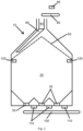
- Fig. 1 shows a silo 10.
- a bulk material is stored in a storage area 20.
- This bulk material can be removed via the three removal devices 30 shown here at the lower end of the storage area 20.
- the bulk material can be removed using the material removal 100, in the example shown Conveyor belt, to be removed.
- New bulk material can be fed to the silo 10 via a material feed 80, in the example shown a conveyor belt, and an introduction device 40.
- the introduction device 40 has a distribution device 60, which is arranged to be rotatable about the central axis of the silo 10.
- the distribution device 60 is designed to be telescopic in order to be able to achieve different radial distances with bulk material.
- the silo 10 has two third sensors 120, which detect the surface of the bulk material.
- the silo 10 has a first sensor 90, which detects the bulk material on the first material feed 80 and, for example, measures the particle size.
- the silo 10 has three second sensors 110, which measure the bulk material transported away, for example the particle size of the bulk material.
- Silo 10 shown corresponds to the one in Fig. 1 silo 10 shown, but with a cone 50.
- the silo 10 has a cone 50, the cone 50 having openings.
- the introduction device 40 has a distribution device 60, which is arranged to be rotatable about the central axis of the silo 10.
- Fig. 3 shows a second alternative embodiment of the silo 10.
- the silo 10 has closure devices 70, which can open and close the openings in the cone.
- the supply of bulk material takes place centrally via the introduction device 40.
- the targeted distribution of the bulk material takes place by opening and closing the openings using the closure devices 70.
Landscapes
- Physics & Mathematics (AREA)
- Engineering & Computer Science (AREA)
- General Physics & Mathematics (AREA)
- Electromagnetism (AREA)
- Fluid Mechanics (AREA)
- Radar, Positioning & Navigation (AREA)
- Remote Sensing (AREA)
- Thermal Sciences (AREA)
- Mechanical Engineering (AREA)
- Acoustics & Sound (AREA)
- Computer Networks & Wireless Communication (AREA)
- Filling Or Emptying Of Bunkers, Hoppers, And Tanks (AREA)
Description
- Die Erfindung betrifft ein Verfahren zum Auftragen von Schüttgut in ein Silo.
- In einem Silo werden Schüttgüter gelagert, welche regelmäßig zur Verwendung in weiteren Schritten entnommen werden. Um in den weiteren Verfahrensschritten eine gleichmäßige Produktqualität sicher zu stellen, ist eine möglichst gleichmäßige Produktzuführung wünschenswert. Daher sind alle Prozesse, welche zu einer Einmischung von Schüttgüter in einem Silo führen, negativ für darauffolgende Prozessschritte.
- Aus der
DE 35 20 498 A1 ist eine Speichereinrichtung für Schüttgut mit einer Verteilersäule bekannt. - Aus der
EP 1 897 829 A1 ist ein Verfahren zum Befüllen eines Großraumsilos ohne Toträume für die Luftströmung zur gleichmäßigen Verteilung bekannt. - Aus der
DE 35 26 503 A1 ist ein Verfahren zum gleichmäßigen Beschicken eines Silos mit einer Mehrzahl an Aufgabestellen bekannt. - Aus der
DE 7004062 U ist eine Vorrichtung zum gleichmäßigen Beschicken von Silos für runde und eckige Lagerräume bekannt. - Aus der
US 4 399 846 A ist ein Mechanismus zu Verteilung von festen Partikeln bekannt. - Aus der
KR 101 611 795 B1 - Aus der
JP H07 181073 A - Aus der
US 6 729 365 B1 ist ein Verteilsystem für ein Silo bekannt. - Aus der
DE 101 06 176 A1 ist ein ausrichtbarer Messkopf und eine den Messkopf verwendende Füllstandvorrichtung bekannt. - Es hat sich gezeigt, dass durch die Entnahme von Schüttgut am unteren Ende des Silos es zu Unebenheiten im Schüttgut kommt. Diese Unebenheiten führen dazu, dass es zu Rutschungen im Schüttgut kommt. Bei solchen Rutschungen verhalten sich unterschiedliche Materialien mit unterschiedlicher Korngröße unterschiedlich, sodass es zu einer Entmischung kommen kann.
- Aufgabe der Erfindung ist es, eine Entmischung des Schüttgutes, beispielsweise durch Verrutschen, zu vermeiden oder wenigstens zu reduzieren.
- Gelöst wird diese Aufgabe durch das Verfahren mit den in Anspruch 1 angegebenen Merkmalen, ein Silo mit den in Anspruch 8 angegebenen Merkmalen sowie durch die Verwendung eines Silos zur Durchführung des Verfahrens mit den in Anspruch 15 angegebenen Merkmalen. Vorteilhafte Weiterbildungen ergeben sich aus den Unteransprüchen, der nachfolgenden Beschreibung sowie den Zeichnungen.
- Für das erfindungsgemäße Verfahren zum Betreiben eines Silos für ein Schüttgut wird ein Silo einer Schüttgutzuführung zur ortsaufgelösten Zuführung von Schüttgut ausgewählt.
- Zunächst wird wobei die Oberfläche des Schüttgutes im Lagerbereich ortsaufgelöst erfasst. Hierdurch wird ein Höhenprofil erfasst. Aus dem Höhenprofil lassen sich leicht Bereiche identifizieren, bei welchen die Oberfläche gegenüber dem Mittelwert der Gesamtoberfläche ein höheres oder niedrigeres Niveau aufweist.
- Es wird wenigstens ein erster Bereich der Oberfläche des Schüttguts identifiziert, wobei der erste Bereich der Oberfläche gegenüber dem Mittelwert der Gesamtoberfläche des Schüttgutes ein niedrigeres Niveau aufweist. Gibt es mehr als einen Bereich, dessen Oberfläche gegenüber dem Mittelwert der Gesamtoberfläche des Schüttgutes ein niedrigeres Niveau aufweist, so kann der erste Bereich ausgewählt werden aufgrund der Differenz zwischen der Höhe der Oberfläche im ersten Bereich und dem Mittelwert der Gesamtoberfläche. Alternativ oder zusätzlich kann die Fläche und/oder das sich aus Fläche und Höhenunterschied ergebende Volumen berücksichtigt werden. Alternativ oder zusätzlich kann die Steilheit (erste Ableitung der Oberfläche) berücksichtigt werden, da das Risiko für Verrutschungen umso höher ist, um so steiler die Oberfläche verläuft. Somit weist der erste Bereich eine erhöhte Gefährdung auf, dass Schüttgut beispielsweise durch Rutschung aus umliegenden Bereichen in diesem ersten Bereich gelangt und dadurch zu einer Entmischung des Schüttguts führt. Um dieses zu verhindern wird die Zuführung von Schüttgut in den ersten Bereich gerichtet.
- In einer weiteren Ausführungsform der Erfindung wird jeweils nur ein erster Teilbereich der Oberfläche des Schüttgutes erfasst wird, während Schüttgut in einem zweiten Teilbereich eingebracht wird. Hierbei ist der erste Teilbereich vom zweiten Teilbereich verschieden. Hierdurch kann eine Störung der Erfassung der Oberfläche durch herabfallendes Schüttgut vermieden werden.
- In einer weiteren Ausführungsform der Erfindung erfolgt die Einbringung von Schüttgut in einem zweiten Teilbereich, wobei der zweite Teilbereich rotiert wird. Hierbei kann zum einen die radiale Einbringung variiert werden, um beispielsweise mehr mittig oder mehr an der Außenseite Schüttgut einzubringen. Des Weiteren kann die Rotationsgeschwindigkeit variiert werden, um unterschiedliche Schüttgutmengen in unterschiedliche Bereiche einzubringen. Alternativ oder zusätzlich kann die eingebrachte Schüttgutmenge zeitlich variiert werden, sodass Bereiche, in welchem beispielsweise kein Schüttgut eingebracht werden soll, zwar überstrichen aber nicht mit Schüttgut aufgefüllt werden. Insbesondere wird umso mehr Schüttgut in einen Bereich eingebracht, je niedriger das Niveau dieses Bereiches im Vergleich zur gesamten Oberfläche des Schüttguts ist.
- In einer weiteren Ausführungsform der Erfindung wird wenigstens während des Einbringens von Schüttgut und wenigstens zeitweise die Oberfläche des Schüttguts im Lagerbereich des Silos erfasst. Die Erfassung der Oberfläche kann beispielsweise kontinuierlich erfolgen. Da während des Einbringens von Schüttgut dieses von oben auf die Oberfläche fällt, ist regelmäßig mit einer Störung der Erfassung zu rechnen. Daher kann es vorteilhaft sein, die Oberfläche nicht kontinuierlich beziehungsweise wenigstens nicht kontinuierlich vollflächig zu erfassen. Beispielsweise kann nur ein Teil der Oberfläche erfasst werden, in welchem gerade kein Schüttgut eingebracht wird. Alternativ kann in Pausen der Einbringung eine Erfassung erfolgen. Weiter kann die Oberfläche mit verschiedenen Messmethoden erfasst werden, welche sich ergänzen, sodass nicht für jede einzelne Erfassungsmethode eine kontinuierliche Erfassung benötigt wird. Beispielsweise und bevorzugt erfolgt die Erfassung der Oberfläche des Schüttgutes optisch, akustisch und/oder mittels Radar.
- In einer weiteren Ausführungsform der Erfindung wird wenigstens eine Materialeigenschaft des zugeführten Schüttgutes bestimmt. Die bestimmte Materialeigenschaft des zugeführten Schüttgutes wird zur Auswahl des Bereichs der Oberfläche des Schüttgutes, in welchen das Schüttgut eingebracht werden soll, berücksichtigt. Beispielsweise und insbesondere kann die Materialeigenschaft eine Temperatur sein. In diesem Fall werden heiße Materialien, welche zu einer Beschädigung der Außenwand führen könnten, eher in die Mitte des Silos eingebracht.
- In einer weiteren Ausführungsform der Erfindung wird die erfasste Materialeigenschaft des zugeführten Schüttguts bestimmt und gespeichert. Da das zugeführte Material regelmäßig schwankende Eigenschaften aufweist, zum Beispiel Korngrößen, kann hierdurch über längere Sicht eine gleichmäßige Verteilung erreicht werden. In Bereiche, in welche zuletzt hauptsächlich Schüttgut mit kleiner Korngröße eingebracht wurde, wird bevorzugt Schüttgut mit größerer Korngröße nachgeführt und andersherum. Dieses führt zu einer homogeneren Mischung des Schüttguts was zum einen zu einer besseren Stabilität des Schüttguts im Silo und zum anderen zu einem homogeneren Produkt führt, welches aus dem Silo entnommen wird.
- In einer weiteren alternativen Ausführungsform wird die erfasste Materialeigenschaft des zugeführten Schüttguts bestimmt und gespeichert. Die Information wird jedoch dazu genutzt, an bestimmten Stellen im Silo Material mit bestimmten Eigenschaften einzulagern. So kann beispielsweise an einer ersten Stelle eher Material mit einer großen Korngröße und an einer zweiten Stelle eher Material mit einer kleinen Korngröße abgelegt werden. Hierdurch ist es später gezielt möglich, verschiedene Korngrößen aus einem Silo zu entnehmen. Auf eine Trennung, zum Beispiel durch Trennwände, wird in dieser alternativen Ausführungsform verzichtet.
- Diese alternativ Ausführungsform kann vorteilhaft sein, wenn beispielsweise der ankommende Materialstrom regelmäßig wiederkehrende Schwankungen einer Eigenschaft aufweist. Dann kann Material mit vorwiegend gleicher Eigenschaft auch bevorzugt an eine bestimmte Stelle des Silos eingelagert werden. Die auf diese Stelle des Silos zugreifenden Siloausläufe könnten dann gezielt Material mit anderen Eigenschaften austragen und verschiedenen Verbrauchern gezielt zuführen. Vorteilhaft kann dieses beispielshaft bei Klinkersilos sein, welchen meist mehrere Mahlanlagen nachgeschaltet sind, die vom Typ unterschiedlich sein können. Unterschiedliche Typen können mit mehr oder weniger feinem Material mehr oder weniger gut betrieben werden. Somit kann durch die gezielte Zuführung von Material mit den richtigen Eigenschaften zur entsprechenden Mahlanlage des passenden Typs sich dann ein Anlagenoptimierungspotential bezüglich Produktqualität und/oder Betriebskosten ergeben. Wenn es beispielsweise zu Sonderereignisse im Zutransport kommt, beispielsweise einen Ofenschuss mit sehr heißem Material oder ein An- oder Abfahrvorgang des Ofens, dann können diese Schwankungen beziehungswiese Veränderungen bestimmter Eigenschaften gezielt in bestimmte Bereiche des Silos eingefüllt werden.
- In einer weiteren Ausführungsform der Erfindung wird wenigstens eine Materialeigenschaft des abgeführten Schüttgutes bestimmt wird, wobei die bestimmte Materialeigenschaft des abgeführten Schüttgutes zur Auswahl des Bereichs der Oberfläche des zugeführten Schüttgutes, in welchen das zugeführte Schüttgut eingebracht werden soll, berücksichtigt wird. Besonders bevorzugt wird sowohl eine Materialeigenschaft des zugeführten Schüttguts als auch eine Materialeigenschaft des abgeführten Schüttguts bestimmt. Hierbei handelt es sich beispielsweise und insbesondere um Korngröße und/oder Korngrößenverteilung. Wird durch die Entnahme festgestellt, dass in einem Bereich beispielsweise sich insbesondere Schüttgut mit einer kleinen Korngröße befindet, so kann in diesem Bereich Material mit einer größeren Korngröße verstärkt zugeführt werden, um zu einer homogeneren Durchmischung des Schüttguts im Silo zu gelangen.
- In einem weiteren Aspekt betrifft die Erfindung ein Silo für ein Schüttgut. Das Silo weist einen Lagerbereich und wenigstens eine erste Entnahmevorrichtung auf. Die erste Entnahmevorrichtung ist am unteren Ende des Lagerbereichs angeordnet. Das Silo weist ferner eine Schüttgutzuführung auf. Die Schüttgutzuführung weist wenigstens eine erste Einbringvorrichtung auf, wobei die erste Einbringvorrichtung oberhalb des Lagerbereichs angeordnet ist. Die Schüttgutzuführung ist zur ortsaufgelösten Zuführung von Schüttgut ausgebildet.
- Erfindungsgemäß weist das Silo wenigstens einen dritten Sensor auf, wobei der wenigstens eine dritte Sensor zur ortaufgelösten Erfassung der Oberfläche des Schüttguts im Lagerbereich ausgebildet ist. Bevorzugt erfasst der wenigstens eine dritte Sensor die Oberfläche mittels Schall, Radar und/oder optisch. Beispielsweise weist das Silo mehrere dritte Sensoren auf, wobei die dritten Sensoren unterschiedliche Messverfahren aufweisen. Beispielsweise wird ein dritter Radarsensor mit einem dritten optischen Sensor kombiniert, um sowohl eine Radarmessung der Oberfläche als auch eine optische Erfassung der Oberfläche zu ermöglichen.
- In einer weiteren Ausführungsform der Erfindung weist die Schüttgutzuführung einen Kegel auf. Der Kegel ist zwischen der ersten Einbringvorrichtung und dem Lagerbereich angeordnet, wobei der Kegel eine nach oben weisende Kegelspitze aufweist. Der Kegel weist Öffnungen auf, wobei Schüttgut aus der ersten Einbringvorrichtung durch die Öffnungen in den Lagerbereich eingebracht werden kann.
- Die Verwendung eines Kegels ist aus mehreren Gründen besonders vorteilhaft. Üblicherweise wird das Silo aus Beton gebaut. Auf diesen Betonbau wird eine Oberkonstruktion üblicherweise aus Stahl gesetzt, welche zum einen die Materialzufuhr sicherstellt und zum anderen das Silo nach oben als Dach abschließt. Ein solcher Kegel kann für die Vergleichmäßigung und ortsaufgelöste Zuführung von Schüttgut Ideal verwendet werden. Gleichzeitig ermöglicht diese Bauweise eine ideale Nachrüstbarkeit auch bei bereits bestehenden Silos.
- In einer weiteren Ausführungsform der Erfindung weist jede Öffnung eine Verschlussvorrichtung auf, wobei die Verschlussvorrichtungen getrennt öffenbar und schließbar, insbesondere einzelnen oder gruppenweise öffenbar und schließbar, sind. Bevorzugt sind die Verschlussvorrichtung in Form von Schiebern ausgebildet. In dieser Ausführungsform wird das Schüttgut zentral auf die Kegelspitze aufgebracht, verteilt sich und gelangt durch die offenen Öffnungen in die Bereiche der Oberfläche, in welche Schüttgut zugeführt werden soll.
- In einer weiteren Ausführungsform der Erfindung weist de Schüttgutzuführung die erste Einbringvorrichtung und eine Verteilvorrichtung auf, wobei Schüttgut aus der erste Einbringvorrichtung über die Verteilvorrichtung in einen örtlich begrenzten Bereich einbringbar ist. Bevorzugt ist die Verteilvorrichtung um die zentrale Achse des Silos rotierbar. Beispielsweise handelt es sich bei der Verteilvorrichtung um eine rotierende Schurre. Besonders bevorzugt ist die Schurre teleskopierbar ausgeführt. Hierdurch ist möglich, Schüttgut gezielt über einzelnen oder mehreren Öffnungen und damit gezielt in einem bestimmten Bereich einzubringen beziehungsweise Bereiche gezielt auszulassen. Bevorzugt weist die Schurre eine zweite Befestigung am oberen Rand des Silomantels auf. Hierdurch kann die Belastung der Schurre, gerade bei größerer Länge, welche bei größerem Durchmesser des Silos auftritt, verringert werden. Die zweite Befestigung ist bevorzugt in Form einer umlaufenden Rolle. Die Rolle kann sich auf einer Schiene oder einer Bahn auf dem Silomantel abstützen.
- In einer weiteren Ausführungsform der Erfindung weist das Silo eine Materialzuführung zur ersten Einbringvorrichtung auf. Die Materialzuführung weist wenigstens einen ersten Sensor aufweist, wobei der erste Sensor zur Erfassung wenigstens einer Eigenschaft des zugeführten Schüttguts ausgebildet ist. Die Eigenschaft ist ausgewählt aus der Gruppe umfassend Temperatur, Korngröße, Korngrößenverteilung. Die Materialzuführung kann beispielsweise in Form eines Förderbandes oder eines Plattenbandes ausgeführt sein.
- In einer weiteren Ausführungsform der Erfindung weist das Silo eine Materialabführung zur Abführung von Schüttgut von der ersten Entnahmevorrichtung auf. Die Materialabführung weist wenigstens einen zweiten Sensor auf. Der zweite Sensor ist zur Erfassung wenigstens eine Eigenschaft des abgeführten Schüttguts ausgebildet, wobei die Eigenschaft ausgewählt ist aus der Gruppe umfassend Korngröße, Korngröße Verteilung, Materialzusammensetzung. Die Materialabführung kann beispielsweise in Form eines Förderbandes oder eines Plattenbands ausgeführt sein.
- In einer weiteren Ausführungsform der Erfindung weist das Silo wenigstens drei, bevorzugt wenigstens sieben, Entnahmevorrichtungen auf. Hierdurch ist zum einen eine schnellere Entnahme größerer Mengen an Schüttgut möglich. Zum anderen ist eine homogenere Entnahme von Schüttgut möglich, wenn ein Silo mit größerem Durchmesser verwendet wird.
- In einer weiteren Ausführungsform der Erfindung weist das Silo einen Durchmesser von 20 m bis 80 m auf.
- In einer weiteren Ausführungsform der Erfindung weist das Silo eine Höhe von 10 m bis 60 m auf.
- Besonders bevorzugt weist das Silo einen runden Querschnitt auf.
- In einem weiteren Aspekt betrifft die Erfindung die Verwendung eines erfindungsgemäßen Silos zur Durchführung des erfindungsgemäßen Verfahrens.
- Nachfolgend ist das erfindungsgemäße Silo anhand zweier in den Zeichnungen dargestellten Ausführungsbeispielen näher erläutert.
-
Fig. 1 Ausführungsform mit Verteilvorrichtung -
Fig. 2 Ausführungsform mit Verteilvorrichtung -
Fig. 3 Ausführungsform mit Verschlussvorrichtungen -
Fig. 1 zeigt ein Silo 10. In dem Silo 10 wird in einem Lagerbereich 20 ein Schüttgut gelagert. Dieses Schüttgut kann über die drei hier gezeigten Entnahmevorrichtungen 30 am unteren Ende des Lagerbereichs 20 entnommen werden. Nach der Entnahme kann das Schüttgut mittels der Materialabführung 100, im gezeigten Beispiel einem Förderband, abgeführt werden. Neues Schüttgut kann dem Silo 10 über eine Materialzuführung 80, im gezeigten Beispiel ein Förderband, und eine Einbringvorrichtung 40 zugeführt werden. Die Einbringvorrichtung 40 weist eine Verteilvorrichtung 60 auf, welche rotierbar um die zentrale Achse des Silos 10 angeordnet ist. Zusätzlich ist die Verteilvorrichtung 60 teleskopierbar ausgeführt, um verschiedene radiale Abstände mit Schüttgut erreichen zu können. - Um eine prozessuale Steuerung ermöglichen zu können weist das Silo 10 zwei dritte Sensoren 120 auf, welche die Oberfläche des Schüttguts erfassen. Zusätzlich weist das Silo 10 einen ersten Sensor 90 auf, welcher das Schüttgut auf der ersten Materialzuführung 80 erfasst und beispielsweise die Partikelgröße misst. Ebenso weist das Silo 10 drei zweite Sensoren 110 auf, welche das abtransportierte Schüttgut, beispielsweise die Partikelgröße des Schüttguts, messen.
- Das in
Fig. 2 gezeigte Silo 10 entspricht dem inFig. 1 gezeigtem Silo 10, jedoch mit einem Kegel 50. Um eine Verteilung des Schüttguts im Lagerbereich 20 zu erreichen, sodass die Oberfläche des Schüttguts möglichst eben ist, weist das Silo 10 einen Kegel 50 auf, wobei der Kegel 50 Öffnungen aufweist. Um diese Öffnungen gezielt ansteuern zu können, weist die Einbringvorrichtung 40 eine Verteilvorrichtung 60 auf, welche rotierbar um die zentrale Achse des Silos 10 angeordnet ist. -
Fig. 3 zeigt eine zweite alternative Ausführungsform des Silos 10. Anstelle der Verteilvorrichtung 60 weist das Silo 10 Verschlussvorrichtungen 70 auf, welche die Öffnungen im Kegel öffnen und verschließen können. Die Zuführung von Schüttgut erfolgt zentral über die Einbringvorrichtung 40. Die zielgerichtete Verteilung des Schüttguts erfolgt über das Öffnen und Schließen der Öffnungen mittels der Verschlussvorrichtungen 70. -
- 10
- Silo
- 20
- Lagerbereich
- 30
- Entnahmevorrichtung
- 40
- Einbringvorrichtung
- 50
- Kegel
- 60
- Verteilvorrichtung
- 70
- Verschlussvorrichtung
- 80
- Materialzuführung
- 90
- erster Sensor
- 100
- Materialabführung
- 110
- zweiter Sensor
- 120
- dritter Sensor
Claims (15)
- Verfahren zum Betreiben eines Silos (10) für ein Schüttgut, wobei die Oberfläche des Schüttgutes im Lagerbereich (20) ortsaufgelöst erfasst wird, dadurch gekennzeichnet, dass ein Silo (10) mit einer Schüttgutzuführung zur ortsaufgelösten Zuführung von Schüttgut ausgewählt wird, wobei wenigstens ein erster Bereich der Oberfläche des Schüttguts identifiziert wird, wobei der erste Bereich der Oberfläche gegenüber dem Mittelwert der Gesamtoberfläche des Schüttgutes ein niedrigeres Niveau aufweist, wobei die Zuführung von Schüttgut durch eine Schüttgutzuführung zur ortsaufgelösten Zuführung in den ersten Bereich gerichtet wird.
- Verfahren nach Anspruch 1, dadurch gekennzeichnet, dass jeweils nur ein erster Teilbereich der Oberfläche des Schüttgutes erfasst wird, wobei Schüttgut in einem zweiten Teilbereich eingebracht wird, wobei der erste Teilbereich vom zweiten Teilbereich verschieden ist.
- Verfahren nach einem der vorstehenden Ansprüche, dadurch gekennzeichnet, dass die Einbringung von Schüttgut in einem zweiten Teilbereich erfolgt, wobei der zweite Teilbereich rotiert wird.
- Verfahren nach einem der vorstehenden Ansprüche, dadurch gekennzeichnet, dass wenigstens während des Einbringens von Schüttgut wenigstens zeitweise die Oberfläche des Schüttguts im Lagerbereich (20) des Silos (10) erfasst wird.
- Verfahren nach Anspruch 4, dadurch gekennzeichnet, dass die Oberfläche des Schüttguts optisch, akustisch und/oder mittels Radar erfasst wird.
- Verfahren nach einem der vorstehenden Ansprüche, dadurch gekennzeichnet, dass wenigstens eine Materialeigenschaft des zugeführten Schüttgutes bestimmt wird, wobei die bestimmte Materialeigenschaft des zugeführten Schüttgutes zur Auswahl des Bereichs der Oberfläche des Schüttgutes, in welchen das Schüttgut eingebracht werden soll, berücksichtigt wird.
- Verfahren nach einem der vorstehenden Ansprüche, dadurch gekennzeichnet, dass wenigstens eine Materialeigenschaft des abgeführten Schüttgutes bestimmt wird, wobei die bestimmte Materialeigenschaft des abgeführten Schüttgutes zur Auswahl des Bereichs der Oberfläche des zugeführten Schüttgutes, in welchen das zugeführte Schüttgut eingebracht werden soll, berücksichtigt wird.
- Silo (10) für ein Schüttgut, wobei das Silo (10) einen Lagerbereich (20) aufweist, wobei das Silo (10) wenigstens eine erste Entnahmevorrichtung (30) aufweist, wobei die erste Entnahmevorrichtung (30) am unteren Ende des Lagerbereichs (20) angeordnet ist, wobei das Silo (10) eine Schüttgutzuführung aufweist, wobei die Schüttgutzuführung wenigstens eine erste Einbringvorrichtung (40) aufweist, wobei die erste Einbringvorrichtung (40) oberhalb des Lagerbereichs (20) angeordnet ist, wobei das Silo (10) wenigstens einen dritten Sensor (120) aufweist, wobei der wenigstens eine dritte Sensor (120) zur ortsaufgelösten Erfassung der Oberfläche des Schüttguts im Lagerbereich (20) ausgebildet ist, dadurch gekennzeichnet, dass die Schüttgutzuführung (40) zur ortaufgelösten Zuführung von Schüttgut ausgebildet ist.
- Silo (10) nach Anspruch 8, dadurch gekennzeichnet, dass die Schüttgutzuführung einen Kegel (50) aufweist, wobei der Kegel zwischen der ersten Einbringvorrichtung (40) und dem Lagerbereich (20) angeordnet ist, wobei der Kegel (50) eine nach oben weisende Kegelspitze aufweist, wobei der Kegel (50) Öffnungen aufweist, wobei Schüttgut aus der ersten Einbringvorrichtung (40) durch die Öffnungen in den Lagerbereich (20) eingebracht werden kann.
- Silo (10) nach einem der Ansprüche 8 bis 9, dadurch gekennzeichnet, dass die Schüttgutzuführung die erste Einbringvorrichtung (40) und eine Verteilvorrichtung (60) aufweist, wobei Schüttgut aus der erste Einbringvorrichtung (40) über die Verteilvorrichtung (60) in einen örtlich begrenzten Bereich einbringbar ist.
- Silo (10) nach Anspruch 10, dadurch gekennzeichnet, dass die Verteilvorrichtung (60) um die zentrale Achse des Silos (10) rotierbar ist.
- Silo (10) nach einem der Ansprüche 8 bis 11, dadurch gekennzeichnet, dass das Silo (10) eine Materialzuführung (80) zur ersten Einbringvorrichtung (40) aufweist, wobei die Materialzuführung (80) wenigstens einen ersten Sensor (90) aufweist, wobei der erste Sensor (90) zur Erfassung wenigstens einer Eigenschaft des zugeführten Schüttguts ausgebildet ist, wobei die Eigenschaft ausgewählt ist aus der Gruppe umfassend Temperatur, Korngröße, Korngrößenverteilung.
- Silo (10) nach einem der Ansprüche 8 bis 12, dadurch gekennzeichnet, dass das Silo (10) eine Materialabführung (100) zur Abführung von Schüttgut von der ersten Entnahmevorrichtung (30) aufweist, wobei die Materialabführung (100) wenigstens einen zweiten Sensor (110) aufweist, wobei der zweite Sensor (110) zur Erfassung wenigstens ein Eigenschaft des abgeführt Schüttguts ausgebildet ist, wobei die Eigenschaft ausgewählt ist aus der Gruppe umfassend Korngröße, Korngröße Verteilung, Materialzusammensetzung.
- Silo (10) nach einem der Ansprüche 8 bis 13, dadurch gekennzeichnet, dass der wenigstens eine dritte Sensor (120) die Oberfläche mittels Schall, Radar und/oder optisch erfasst.
- Verwendung eines Silos (10) nach einem der Ansprüche 8 bis 14 zur Durchführung des Verfahrens nach einem der Ansprüche 1 bis 7.
Applications Claiming Priority (2)
| Application Number | Priority Date | Filing Date | Title |
|---|---|---|---|
| DE102019204833.1A DE102019204833A1 (de) | 2019-04-04 | 2019-04-04 | Homogenisierter Materialauftrag für ein Silo |
| PCT/EP2020/058692 WO2020201075A1 (de) | 2019-04-04 | 2020-03-27 | Homogenisierter materialeintrag für ein silo |
Publications (3)
| Publication Number | Publication Date |
|---|---|
| EP3948179A1 EP3948179A1 (de) | 2022-02-09 |
| EP3948179C0 EP3948179C0 (de) | 2024-01-03 |
| EP3948179B1 true EP3948179B1 (de) | 2024-01-03 |
Family
ID=70058345
Family Applications (1)
| Application Number | Title | Priority Date | Filing Date |
|---|---|---|---|
| EP20715813.0A Active EP3948179B1 (de) | 2019-04-04 | 2020-03-27 | Homogenisierter materialeintrag für ein silo |
Country Status (3)
| Country | Link |
|---|---|
| EP (1) | EP3948179B1 (de) |
| DE (1) | DE102019204833A1 (de) |
| WO (1) | WO2020201075A1 (de) |
Families Citing this family (1)
| Publication number | Priority date | Publication date | Assignee | Title |
|---|---|---|---|---|
| CN112299036A (zh) * | 2020-11-27 | 2021-02-02 | 中冶京诚工程技术有限公司 | 一种球形料库和球形料库系统 |
Citations (1)
| Publication number | Priority date | Publication date | Assignee | Title |
|---|---|---|---|---|
| DE10106176B4 (de) * | 2001-02-10 | 2007-08-09 | Vega Grieshaber Kg | Ausrichtbarer Messkopf und diesen verwendende Füllstandsmessvorrichtung und -verfahren |
Family Cites Families (12)
| Publication number | Priority date | Publication date | Assignee | Title |
|---|---|---|---|---|
| FR2031885A7 (de) | 1969-02-12 | 1970-11-20 | Ameco Sa | |
| US3576262A (en) * | 1969-06-06 | 1971-04-27 | Us Interior | Rotary particle distributor for minimizing particle size segregation in a bin |
| US4272028A (en) * | 1977-01-10 | 1981-06-09 | Cobb Wayne E | Spreader for and operative by a granular product |
| BR8002400A (pt) * | 1980-04-18 | 1981-12-01 | Petroleo Brasileiro Sa | Mecanismo para distribuicao granulometrica de particulas solidas |
| GR851396B (de) | 1984-06-08 | 1985-11-25 | Reynolds Metals Co | |
| DE3526503A1 (de) | 1985-07-24 | 1987-01-29 | Peters Ag Claudius | Vorrichtung zum gleichmaessigen beschicken eines silos an einer mehrzahl von aufgabestellen |
| FR2595338B3 (fr) * | 1986-03-07 | 1988-02-26 | Ottosson John | Distributeur pour silo |
| JPH07181073A (ja) * | 1993-12-21 | 1995-07-18 | Toray Ind Inc | 超音波粒面測定装置 |
| US6729365B1 (en) * | 2003-03-28 | 2004-05-04 | Laval Cote | Distribution device for use with a silo |
| EP1897829B1 (de) | 2006-09-08 | 2008-07-30 | IBAU HAMBURG Ingenieurgesellschaft Industriebau mbH | Verfahren zum Befüllen von Grossraumlagersilos mit einem fluidisierbaren Material und Anordnung dafür |
| KR101611795B1 (ko) * | 2015-05-06 | 2016-04-11 | 비디아이 주식회사 | 소화설비 시스템을 구비한 석탄 사일로 |
| CN109178976A (zh) * | 2018-11-05 | 2019-01-11 | 青岛朗夫包装有限公司 | 一种聚氯乙烯输送组件集装箱装卸装置及物流系统 |
-
2019
- 2019-04-04 DE DE102019204833.1A patent/DE102019204833A1/de not_active Ceased
-
2020
- 2020-03-27 EP EP20715813.0A patent/EP3948179B1/de active Active
- 2020-03-27 WO PCT/EP2020/058692 patent/WO2020201075A1/de not_active Ceased
Patent Citations (1)
| Publication number | Priority date | Publication date | Assignee | Title |
|---|---|---|---|---|
| DE10106176B4 (de) * | 2001-02-10 | 2007-08-09 | Vega Grieshaber Kg | Ausrichtbarer Messkopf und diesen verwendende Füllstandsmessvorrichtung und -verfahren |
Also Published As
| Publication number | Publication date |
|---|---|
| DE102019204833A1 (de) | 2020-10-08 |
| EP3948179A1 (de) | 2022-02-09 |
| EP3948179C0 (de) | 2024-01-03 |
| WO2020201075A1 (de) | 2020-10-08 |
Similar Documents
| Publication | Publication Date | Title |
|---|---|---|
| DE69626731T2 (de) | Körnchenbarriere und Körnchenwägeapparat damit | |
| DE2703329A1 (de) | Anordnung zum niveaugleichen auffuellen von senkrechtstehenden behaeltern | |
| EP3472544B1 (de) | Vorrichtung und verfahren zur wärmebehandlung von mineralischem gut | |
| WO2016150835A1 (de) | Formsandkühler | |
| EP0292581A1 (de) | Verfahren zum Streuen eines Spänevlieses | |
| WO2015075263A1 (de) | Vorrichtung und verfahren zur herstellung eines geblähten granulats | |
| EP3948179A1 (de) | Homogenisierter materialeintrag für ein silo | |
| DE102016113014A1 (de) | Streuanlage und Verfahren zur Herstellung einer Streugutmatte im Zuge der Herstellung von Werkstoffplatten | |
| EP2959977B1 (de) | Doppelschubzentrifuge sowie schubbodeneinrichtung | |
| EP2884256B1 (de) | Radiometrische dichteprofil-messanordnung | |
| DE2122518B2 (de) | Vorrichtung zum Einspeichern von Schüttgut in zum Böschungswinkel parallelen Schichten | |
| DE102018108730A1 (de) | Vereinzelungsmaschine | |
| DE2814494C2 (de) | Vorrichtung zum Aufgeben einer Sintermischung | |
| DE102016103385B4 (de) | Abwasseraufbereitungsanlagenausrüstung | |
| DE4413864C2 (de) | Adsorptionsmittelreaktor mit einer Mehrzahl von Abzugstrichtern zum Austragen von schüttfähigem Adsorptionsmittel | |
| AT413759B (de) | Aufgabevorrichtung für eine bandsintermaschine | |
| EP1801036B1 (de) | Verwendung von Wandeinbauten zur Verminderung von Geräuschen und Schwingungen bei der Entleerung von Silos | |
| EP4230779A1 (de) | Spinnereivorbereitungsmaschine | |
| EP2960047B1 (de) | Sortiervorrichtung für eine Kompaktieranlage | |
| EP0121599A2 (de) | Verfahren und Vorrichtung zur pneumatischen Förderung von Feingut | |
| EP3513643B1 (de) | Verteilmaschine | |
| DE102017118867A1 (de) | Verladekopf eines pneumatischen Verladesystems für Schüttgüter | |
| DE9407260U1 (de) | Ausgabevorrichtung für scheibenförmige Parktickets | |
| DE2757527A1 (de) | Vorrichtung zur verbesserung des fliessverhaltens von schwerfliessendem schuettgut | |
| BE1027118B1 (de) | Rundlager |
Legal Events
| Date | Code | Title | Description |
|---|---|---|---|
| STAA | Information on the status of an ep patent application or granted ep patent |
Free format text: STATUS: UNKNOWN |
|
| STAA | Information on the status of an ep patent application or granted ep patent |
Free format text: STATUS: THE INTERNATIONAL PUBLICATION HAS BEEN MADE |
|
| PUAI | Public reference made under article 153(3) epc to a published international application that has entered the european phase |
Free format text: ORIGINAL CODE: 0009012 |
|
| STAA | Information on the status of an ep patent application or granted ep patent |
Free format text: STATUS: REQUEST FOR EXAMINATION WAS MADE |
|
| 17P | Request for examination filed |
Effective date: 20211104 |
|
| AK | Designated contracting states |
Kind code of ref document: A1 Designated state(s): AL AT BE BG CH CY CZ DE DK EE ES FI FR GB GR HR HU IE IS IT LI LT LU LV MC MK MT NL NO PL PT RO RS SE SI SK SM TR |
|
| RAP3 | Party data changed (applicant data changed or rights of an application transferred) |
Owner name: THYSSENKRUPP AG Owner name: THYSSENKRUPP INDUSTRIAL SOLUTIONS AG |
|
| RAP3 | Party data changed (applicant data changed or rights of an application transferred) |
Owner name: THYSSENKRUPP INDUSTRIAL SOLUTIONS AG Owner name: THYSSENKRUPP AG |
|
| RAP3 | Party data changed (applicant data changed or rights of an application transferred) |
Owner name: THYSSENKRUPP AG Owner name: THYSSENKRUPP INDUSTRIAL SOLUTIONS AG |
|
| DAV | Request for validation of the european patent (deleted) | ||
| DAX | Request for extension of the european patent (deleted) | ||
| REG | Reference to a national code |
Ref country code: DE Ref legal event code: R079 Free format text: PREVIOUS MAIN CLASS: G01F0013000000 Ipc: B65D0088260000 Ref country code: DE Ref legal event code: R079 Ref document number: 502020006618 Country of ref document: DE Free format text: PREVIOUS MAIN CLASS: G01F0013000000 Ipc: B65D0088260000 |
|
| GRAP | Despatch of communication of intention to grant a patent |
Free format text: ORIGINAL CODE: EPIDOSNIGR1 |
|
| STAA | Information on the status of an ep patent application or granted ep patent |
Free format text: STATUS: GRANT OF PATENT IS INTENDED |
|
| RAP1 | Party data changed (applicant data changed or rights of an application transferred) |
Owner name: THYSSENKRUPP AG Owner name: THYSSENKRUPP POLYSIUS GMBH |
|
| RIC1 | Information provided on ipc code assigned before grant |
Ipc: B65G 69/10 20060101ALI20230913BHEP Ipc: B65G 69/04 20060101ALI20230913BHEP Ipc: B65D 88/54 20060101ALI20230913BHEP Ipc: G01F 22/00 20060101ALI20230913BHEP Ipc: G01S 15/88 20060101ALI20230913BHEP Ipc: G01S 13/88 20060101ALI20230913BHEP Ipc: G01F 23/296 20220101ALI20230913BHEP Ipc: G01F 23/292 20060101ALI20230913BHEP Ipc: G01F 23/284 20060101ALI20230913BHEP Ipc: G01F 23/28 20060101ALI20230913BHEP Ipc: G01F 13/00 20060101ALI20230913BHEP Ipc: G01S 13/87 20060101ALI20230913BHEP Ipc: G01S 13/86 20060101ALI20230913BHEP Ipc: B65D 88/26 20060101AFI20230913BHEP |
|
| INTG | Intention to grant announced |
Effective date: 20230927 |
|
| GRAS | Grant fee paid |
Free format text: ORIGINAL CODE: EPIDOSNIGR3 |
|
| GRAA | (expected) grant |
Free format text: ORIGINAL CODE: 0009210 |
|
| STAA | Information on the status of an ep patent application or granted ep patent |
Free format text: STATUS: THE PATENT HAS BEEN GRANTED |
|
| AK | Designated contracting states |
Kind code of ref document: B1 Designated state(s): AL AT BE BG CH CY CZ DE DK EE ES FI FR GB GR HR HU IE IS IT LI LT LU LV MC MK MT NL NO PL PT RO RS SE SI SK SM TR |
|
| REG | Reference to a national code |
Ref country code: GB Ref legal event code: FG4D Free format text: NOT ENGLISH |
|
| REG | Reference to a national code |
Ref country code: CH Ref legal event code: EP |
|
| REG | Reference to a national code |
Ref country code: DE Ref legal event code: R096 Ref document number: 502020006618 Country of ref document: DE |
|
| REG | Reference to a national code |
Ref country code: IE Ref legal event code: FG4D Free format text: LANGUAGE OF EP DOCUMENT: GERMAN |
|
| U01 | Request for unitary effect filed |
Effective date: 20240110 |
|
| U07 | Unitary effect registered |
Designated state(s): AT BE BG DE DK EE FI FR IT LT LU LV MT NL PT SE SI Effective date: 20240118 |
|
| PG25 | Lapsed in a contracting state [announced via postgrant information from national office to epo] |
Ref country code: ES Free format text: LAPSE BECAUSE OF FAILURE TO SUBMIT A TRANSLATION OF THE DESCRIPTION OR TO PAY THE FEE WITHIN THE PRESCRIBED TIME-LIMIT Effective date: 20240103 |
|
| PG25 | Lapsed in a contracting state [announced via postgrant information from national office to epo] |
Ref country code: ES Free format text: LAPSE BECAUSE OF FAILURE TO SUBMIT A TRANSLATION OF THE DESCRIPTION OR TO PAY THE FEE WITHIN THE PRESCRIBED TIME-LIMIT Effective date: 20240103 |
|
| U20 | Renewal fee for the european patent with unitary effect paid |
Year of fee payment: 5 Effective date: 20240325 |
|
| PG25 | Lapsed in a contracting state [announced via postgrant information from national office to epo] |
Ref country code: IS Free format text: LAPSE BECAUSE OF FAILURE TO SUBMIT A TRANSLATION OF THE DESCRIPTION OR TO PAY THE FEE WITHIN THE PRESCRIBED TIME-LIMIT Effective date: 20240503 |
|
| PG25 | Lapsed in a contracting state [announced via postgrant information from national office to epo] |
Ref country code: GR Free format text: LAPSE BECAUSE OF FAILURE TO SUBMIT A TRANSLATION OF THE DESCRIPTION OR TO PAY THE FEE WITHIN THE PRESCRIBED TIME-LIMIT Effective date: 20240404 |
|
| PG25 | Lapsed in a contracting state [announced via postgrant information from national office to epo] |
Ref country code: RS Free format text: LAPSE BECAUSE OF FAILURE TO SUBMIT A TRANSLATION OF THE DESCRIPTION OR TO PAY THE FEE WITHIN THE PRESCRIBED TIME-LIMIT Effective date: 20240403 Ref country code: HR Free format text: LAPSE BECAUSE OF FAILURE TO SUBMIT A TRANSLATION OF THE DESCRIPTION OR TO PAY THE FEE WITHIN THE PRESCRIBED TIME-LIMIT Effective date: 20240103 |
|
| PG25 | Lapsed in a contracting state [announced via postgrant information from national office to epo] |
Ref country code: CZ Free format text: LAPSE BECAUSE OF FAILURE TO SUBMIT A TRANSLATION OF THE DESCRIPTION OR TO PAY THE FEE WITHIN THE PRESCRIBED TIME-LIMIT Effective date: 20240103 |
|
| PG25 | Lapsed in a contracting state [announced via postgrant information from national office to epo] |
Ref country code: RS Free format text: LAPSE BECAUSE OF FAILURE TO SUBMIT A TRANSLATION OF THE DESCRIPTION OR TO PAY THE FEE WITHIN THE PRESCRIBED TIME-LIMIT Effective date: 20240403 Ref country code: NO Free format text: LAPSE BECAUSE OF FAILURE TO SUBMIT A TRANSLATION OF THE DESCRIPTION OR TO PAY THE FEE WITHIN THE PRESCRIBED TIME-LIMIT Effective date: 20240403 Ref country code: IS Free format text: LAPSE BECAUSE OF FAILURE TO SUBMIT A TRANSLATION OF THE DESCRIPTION OR TO PAY THE FEE WITHIN THE PRESCRIBED TIME-LIMIT Effective date: 20240503 Ref country code: HR Free format text: LAPSE BECAUSE OF FAILURE TO SUBMIT A TRANSLATION OF THE DESCRIPTION OR TO PAY THE FEE WITHIN THE PRESCRIBED TIME-LIMIT Effective date: 20240103 Ref country code: GR Free format text: LAPSE BECAUSE OF FAILURE TO SUBMIT A TRANSLATION OF THE DESCRIPTION OR TO PAY THE FEE WITHIN THE PRESCRIBED TIME-LIMIT Effective date: 20240404 Ref country code: CZ Free format text: LAPSE BECAUSE OF FAILURE TO SUBMIT A TRANSLATION OF THE DESCRIPTION OR TO PAY THE FEE WITHIN THE PRESCRIBED TIME-LIMIT Effective date: 20240103 |
|
| PG25 | Lapsed in a contracting state [announced via postgrant information from national office to epo] |
Ref country code: PL Free format text: LAPSE BECAUSE OF FAILURE TO SUBMIT A TRANSLATION OF THE DESCRIPTION OR TO PAY THE FEE WITHIN THE PRESCRIBED TIME-LIMIT Effective date: 20240103 |
|
| PG25 | Lapsed in a contracting state [announced via postgrant information from national office to epo] |
Ref country code: PL Free format text: LAPSE BECAUSE OF FAILURE TO SUBMIT A TRANSLATION OF THE DESCRIPTION OR TO PAY THE FEE WITHIN THE PRESCRIBED TIME-LIMIT Effective date: 20240103 |
|
| REG | Reference to a national code |
Ref country code: DE Ref legal event code: R097 Ref document number: 502020006618 Country of ref document: DE |
|
| PG25 | Lapsed in a contracting state [announced via postgrant information from national office to epo] |
Ref country code: SM Free format text: LAPSE BECAUSE OF FAILURE TO SUBMIT A TRANSLATION OF THE DESCRIPTION OR TO PAY THE FEE WITHIN THE PRESCRIBED TIME-LIMIT Effective date: 20240103 |
|
| PG25 | Lapsed in a contracting state [announced via postgrant information from national office to epo] |
Ref country code: SK Free format text: LAPSE BECAUSE OF FAILURE TO SUBMIT A TRANSLATION OF THE DESCRIPTION OR TO PAY THE FEE WITHIN THE PRESCRIBED TIME-LIMIT Effective date: 20240103 |
|
| PG25 | Lapsed in a contracting state [announced via postgrant information from national office to epo] |
Ref country code: SM Free format text: LAPSE BECAUSE OF FAILURE TO SUBMIT A TRANSLATION OF THE DESCRIPTION OR TO PAY THE FEE WITHIN THE PRESCRIBED TIME-LIMIT Effective date: 20240103 Ref country code: SK Free format text: LAPSE BECAUSE OF FAILURE TO SUBMIT A TRANSLATION OF THE DESCRIPTION OR TO PAY THE FEE WITHIN THE PRESCRIBED TIME-LIMIT Effective date: 20240103 Ref country code: RO Free format text: LAPSE BECAUSE OF FAILURE TO SUBMIT A TRANSLATION OF THE DESCRIPTION OR TO PAY THE FEE WITHIN THE PRESCRIBED TIME-LIMIT Effective date: 20240103 |
|
| REG | Reference to a national code |
Ref country code: CH Ref legal event code: PL |
|
| PLBE | No opposition filed within time limit |
Free format text: ORIGINAL CODE: 0009261 |
|
| STAA | Information on the status of an ep patent application or granted ep patent |
Free format text: STATUS: NO OPPOSITION FILED WITHIN TIME LIMIT |
|
| PG25 | Lapsed in a contracting state [announced via postgrant information from national office to epo] |
Ref country code: MC Free format text: LAPSE BECAUSE OF FAILURE TO SUBMIT A TRANSLATION OF THE DESCRIPTION OR TO PAY THE FEE WITHIN THE PRESCRIBED TIME-LIMIT Effective date: 20240103 |
|
| PG25 | Lapsed in a contracting state [announced via postgrant information from national office to epo] |
Ref country code: MC Free format text: LAPSE BECAUSE OF FAILURE TO SUBMIT A TRANSLATION OF THE DESCRIPTION OR TO PAY THE FEE WITHIN THE PRESCRIBED TIME-LIMIT Effective date: 20240103 |
|
| 26N | No opposition filed |
Effective date: 20241007 |
|
| GBPC | Gb: european patent ceased through non-payment of renewal fee |
Effective date: 20240403 |
|
| PG25 | Lapsed in a contracting state [announced via postgrant information from national office to epo] |
Ref country code: GB Free format text: LAPSE BECAUSE OF NON-PAYMENT OF DUE FEES Effective date: 20240403 |
|
| PG25 | Lapsed in a contracting state [announced via postgrant information from national office to epo] |
Ref country code: IE Free format text: LAPSE BECAUSE OF NON-PAYMENT OF DUE FEES Effective date: 20240327 |
|
| PG25 | Lapsed in a contracting state [announced via postgrant information from national office to epo] |
Ref country code: IE Free format text: LAPSE BECAUSE OF NON-PAYMENT OF DUE FEES Effective date: 20240327 Ref country code: GB Free format text: LAPSE BECAUSE OF NON-PAYMENT OF DUE FEES Effective date: 20240403 Ref country code: CH Free format text: LAPSE BECAUSE OF NON-PAYMENT OF DUE FEES Effective date: 20240331 |
|
| U20 | Renewal fee for the european patent with unitary effect paid |
Year of fee payment: 6 Effective date: 20250325 |
|
| PG25 | Lapsed in a contracting state [announced via postgrant information from national office to epo] |
Ref country code: CY Free format text: LAPSE BECAUSE OF FAILURE TO SUBMIT A TRANSLATION OF THE DESCRIPTION OR TO PAY THE FEE WITHIN THE PRESCRIBED TIME-LIMIT; INVALID AB INITIO Effective date: 20200327 |
|
| PG25 | Lapsed in a contracting state [announced via postgrant information from national office to epo] |
Ref country code: HU Free format text: LAPSE BECAUSE OF FAILURE TO SUBMIT A TRANSLATION OF THE DESCRIPTION OR TO PAY THE FEE WITHIN THE PRESCRIBED TIME-LIMIT; INVALID AB INITIO Effective date: 20200327 |
|
| PG25 | Lapsed in a contracting state [announced via postgrant information from national office to epo] |
Ref country code: TR Free format text: LAPSE BECAUSE OF FAILURE TO SUBMIT A TRANSLATION OF THE DESCRIPTION OR TO PAY THE FEE WITHIN THE PRESCRIBED TIME-LIMIT Effective date: 20240103 |
|
| U20 | Renewal fee for the european patent with unitary effect paid |
Year of fee payment: 7 Effective date: 20260326 |
|
| U1N | Appointed representative for the unitary patent procedure changed after the registration of the unitary effect |
Representative=s name: MOSER GOETZE & PARTNER PATENTANWAELTE MBB; DE |