EP3947934B1 - Temperiervorrichtung und brennkraftmaschine mit einer solchen - Google Patents
Temperiervorrichtung und brennkraftmaschine mit einer solchen Download PDFInfo
- Publication number
- EP3947934B1 EP3947934B1 EP19718055.7A EP19718055A EP3947934B1 EP 3947934 B1 EP3947934 B1 EP 3947934B1 EP 19718055 A EP19718055 A EP 19718055A EP 3947934 B1 EP3947934 B1 EP 3947934B1
- Authority
- EP
- European Patent Office
- Prior art keywords
- temperature control
- control device
- bypass
- connection
- housing
- Prior art date
- Legal status (The legal status is an assumption and is not a legal conclusion. Google has not performed a legal analysis and makes no representation as to the accuracy of the status listed.)
- Active
Links
Images


Classifications
-
- F—MECHANICAL ENGINEERING; LIGHTING; HEATING; WEAPONS; BLASTING
- F02—COMBUSTION ENGINES; HOT-GAS OR COMBUSTION-PRODUCT ENGINE PLANTS
- F02B—INTERNAL-COMBUSTION PISTON ENGINES; COMBUSTION ENGINES IN GENERAL
- F02B29/00—Engines characterised by provision for charging or scavenging not provided for in groups F02B25/00, F02B27/00 or F02B33/00 - F02B39/00; Details thereof
- F02B29/04—Cooling of air intake supply
- F02B29/0406—Layout of the intake air cooling or coolant circuit
- F02B29/0418—Layout of the intake air cooling or coolant circuit the intake air cooler having a bypass or multiple flow paths within the heat exchanger to vary the effective heat transfer surface
-
- F—MECHANICAL ENGINEERING; LIGHTING; HEATING; WEAPONS; BLASTING
- F02—COMBUSTION ENGINES; HOT-GAS OR COMBUSTION-PRODUCT ENGINE PLANTS
- F02B—INTERNAL-COMBUSTION PISTON ENGINES; COMBUSTION ENGINES IN GENERAL
- F02B29/00—Engines characterised by provision for charging or scavenging not provided for in groups F02B25/00, F02B27/00 or F02B33/00 - F02B39/00; Details thereof
- F02B29/04—Cooling of air intake supply
- F02B29/045—Constructional details of the heat exchangers, e.g. pipes, plates, ribs, insulation, materials, or manufacturing and assembly
- F02B29/0462—Liquid cooled heat exchangers
-
- F—MECHANICAL ENGINEERING; LIGHTING; HEATING; WEAPONS; BLASTING
- F02—COMBUSTION ENGINES; HOT-GAS OR COMBUSTION-PRODUCT ENGINE PLANTS
- F02B—INTERNAL-COMBUSTION PISTON ENGINES; COMBUSTION ENGINES IN GENERAL
- F02B29/00—Engines characterised by provision for charging or scavenging not provided for in groups F02B25/00, F02B27/00 or F02B33/00 - F02B39/00; Details thereof
- F02B29/04—Cooling of air intake supply
- F02B29/045—Constructional details of the heat exchangers, e.g. pipes, plates, ribs, insulation, materials, or manufacturing and assembly
- F02B29/0475—Constructional details of the heat exchangers, e.g. pipes, plates, ribs, insulation, materials, or manufacturing and assembly the intake air cooler being combined with another device, e.g. heater, valve, compressor, filter or EGR cooler, or being assembled on a special engine location
-
- F—MECHANICAL ENGINEERING; LIGHTING; HEATING; WEAPONS; BLASTING
- F28—HEAT EXCHANGE IN GENERAL
- F28F—DETAILS OF HEAT-EXCHANGE AND HEAT-TRANSFER APPARATUS, OF GENERAL APPLICATION
- F28F27/00—Control arrangements or safety devices specially adapted for heat-exchange or heat-transfer apparatus
- F28F27/02—Control arrangements or safety devices specially adapted for heat-exchange or heat-transfer apparatus for controlling the distribution of heat-exchange media between different channels
-
- F—MECHANICAL ENGINEERING; LIGHTING; HEATING; WEAPONS; BLASTING
- F02—COMBUSTION ENGINES; HOT-GAS OR COMBUSTION-PRODUCT ENGINE PLANTS
- F02B—INTERNAL-COMBUSTION PISTON ENGINES; COMBUSTION ENGINES IN GENERAL
- F02B29/00—Engines characterised by provision for charging or scavenging not provided for in groups F02B25/00, F02B27/00 or F02B33/00 - F02B39/00; Details thereof
- F02B29/04—Cooling of air intake supply
- F02B29/0493—Controlling the air charge temperature
-
- F—MECHANICAL ENGINEERING; LIGHTING; HEATING; WEAPONS; BLASTING
- F28—HEAT EXCHANGE IN GENERAL
- F28D—HEAT-EXCHANGE APPARATUS, NOT PROVIDED FOR IN ANOTHER SUBCLASS, IN WHICH THE HEAT-EXCHANGE MEDIA DO NOT COME INTO DIRECT CONTACT
- F28D21/00—Heat-exchange apparatus not covered by any of the groups F28D1/00 - F28D20/00
- F28D2021/0019—Other heat exchangers for particular applications; Heat exchange systems not otherwise provided for
- F28D2021/008—Other heat exchangers for particular applications; Heat exchange systems not otherwise provided for for vehicles
- F28D2021/0082—Charged air coolers
-
- F—MECHANICAL ENGINEERING; LIGHTING; HEATING; WEAPONS; BLASTING
- F28—HEAT EXCHANGE IN GENERAL
- F28F—DETAILS OF HEAT-EXCHANGE AND HEAT-TRANSFER APPARATUS, OF GENERAL APPLICATION
- F28F2230/00—Sealing means
-
- F—MECHANICAL ENGINEERING; LIGHTING; HEATING; WEAPONS; BLASTING
- F28—HEAT EXCHANGE IN GENERAL
- F28F—DETAILS OF HEAT-EXCHANGE AND HEAT-TRANSFER APPARATUS, OF GENERAL APPLICATION
- F28F2250/00—Arrangements for modifying the flow of the heat exchange media, e.g. flow guiding means; Particular flow patterns
- F28F2250/06—Derivation channels, e.g. bypass
-
- F—MECHANICAL ENGINEERING; LIGHTING; HEATING; WEAPONS; BLASTING
- F28—HEAT EXCHANGE IN GENERAL
- F28F—DETAILS OF HEAT-EXCHANGE AND HEAT-TRANSFER APPARATUS, OF GENERAL APPLICATION
- F28F2275/00—Fastening; Joining
- F28F2275/20—Fastening; Joining with threaded elements
-
- Y—GENERAL TAGGING OF NEW TECHNOLOGICAL DEVELOPMENTS; GENERAL TAGGING OF CROSS-SECTIONAL TECHNOLOGIES SPANNING OVER SEVERAL SECTIONS OF THE IPC; TECHNICAL SUBJECTS COVERED BY FORMER USPC CROSS-REFERENCE ART COLLECTIONS [XRACs] AND DIGESTS
- Y02—TECHNOLOGIES OR APPLICATIONS FOR MITIGATION OR ADAPTATION AGAINST CLIMATE CHANGE
- Y02T—CLIMATE CHANGE MITIGATION TECHNOLOGIES RELATED TO TRANSPORTATION
- Y02T10/00—Road transport of goods or passengers
- Y02T10/10—Internal combustion engine [ICE] based vehicles
- Y02T10/12—Improving ICE efficiencies
Definitions
- the invention relates to a temperature control device with the features of the preamble of claim 1 and an internal combustion engine with at least one such temperature control device.
- Generic temperature control devices are mostly used to cool charge air or - in the case of mixed-charge internal combustion engines - to cool a fuel-air mixture. However, depending on the ambient conditions of the internal combustion engine, it may well be necessary to heat the charge air or the fuel-air mixture using the temperature control device.
- Embodiments known from the prior art are, for example, from US 2016/0273854 A1 , the JP 2013 079589 A or the US 2018/169433 A1 out.
- the temperature control device It may be necessary to supply the heat exchanger of the temperature control device only a portion of the temperature control medium flow present in the inlet tract of the internal combustion engine (for example, but not only, in the case of a two-stage design of the temperature control medium). In such cases, in the prior art, the temperature control device must be bypassed by means of a bypass arranged outside the temperature control device and separate from the temperature control device, which is associated with an increase in the required installation space.
- the object of the invention is to provide a generic temperature control device and an internal combustion engine with such a temperature control device, in which the provision of a bypass is made possible in a compact manner.
- a temperature control device for charge air or a fuel-air mixture of an internal combustion engine has a housing enclosing an interior, which has at least one input port and at least one output port for the charge air to be tempered or the mixture to be tempered and at least one supply port and at least one discharge port for Has temperature control medium, wherein a heat exchanger is arranged or formed in the interior of the housing, via which a heat exchange between temperature control medium and charge air or mixture takes place during operation of the temperature control device.
- At least one bypass is arranged between the at least one supply connection and the at least one discharge connection for temperature control medium (as a structural part of the temperature control device), via which temperature control medium can flow from the at least one supply connection to the at least one discharge connection without entering the heat exchanger.
- the invention therefore provides that the at least one bypass is part of the temperature control device itself and is structurally integrated into it. This results in an extremely compact design without the need for tubing or piping for the at least one bypass that is separate from the temperature control device. From the total flow of temperature control medium, which can enter the at least one supply connection, a partial flow is branched off within the at least one supply connection via the at least one bypass (with another partial flow flowing to the heat exchanger), flows to the at least one discharge connection and leaves the heat exchanger together with one coming partial flow the temperature control device via the at least one discharge connection.
- the at least one bypass is arranged within the interior of the housing, which still represents a more compact design compared to a hose or piping separate from the temperature control device for the at least one bypass.
- an even smaller housing is possible in an exemplary embodiment of the invention if it is provided that the at least one bypass is arranged outside the interior of the housing.
- At least one aperture is arranged in at least one bypass.
- the proportion of partial flow flowing through the at least one bypass can in this case be selected via the free flow cross section of the at least one orifice, which represents the free flow cross section of the at least one bypass.
- the aperture is designed in the form of a perforated plate.
- the at least one aperture is arranged interchangeably in the at least one bypass. This opens up the possibility of selecting a desired partial flow flowing via the at least one bypass for one and the same temperature control device by selecting a suitable aperture (whereby different apertures can have a different free flow cross section).
- the interchangeability of the at least one aperture can be done, for example, in such a way that the at least one aperture can be inserted into a corresponding recess of the at least one bypass from the outside.
- the at least one bypass consists of at least two sections, one of the at least two sections being formed in one piece with the at least one supply connection and/or one of the at least two sections being formed in one piece with the at least one discharge connection.
- This results in a particularly compact design. If, for example, an exchangeable panel is provided, according to the invention this can be arranged (preferably clamped) between the at least two sections of the at least one bypass.
- the at least two sections can be detached from the housing, the cover is replaced and then attached to the housing via the at least two sections.
- At least the at least one supply connection and/or the at least one discharge connection and/or the at least one bypass are arranged together on a cover which also forms the housing. This enables a design in which the remaining temperature control device can be designed according to the prior art.
- the at least one supply connection and/or the at least one discharge connection can be designed in one piece or in several parts.
- the at least one bypass is arranged completely on a single part or on at least two parts (e.g. underside of the at least one bypass) in relation to the at least one supply connection and/or the at least one discharge connection on one part and top of the at least one bypass on another part) is arranged.
- At least a part of the at least one supply connection and/or a part of the at least one discharge connection are or is formed in one piece with the cover, It is preferably provided that the cover is designed as a cast part (made of metal or plastic). This represents a simple manufacturing option.
- the temperature control device is only designed in one stage. In one embodiment of the invention, however, it is provided that the temperature control device is designed in two stages and has a first and a second temperature control branch. In this case, it may be sufficient if the at least one bypass according to the invention is only provided in one of the temperature control branches. If the first and second temperature control branches are fluidically connected in series with respect to the temperature control medium, the at least one bypass can be provided in relation to the flow direction of the temperature control medium in the upstream temperature control branch. In this way, a lower temperature control medium flow required for the upstream temperature control branch (compared to the downstream temperature control branch) can be achieved by a partial flow flowing over the bypass.
- Serially connected temperature control branches can preferably be provided, with the temperature control medium passing through the temperature control branches counter to a flow direction of the charge air to be cooled or the mixture to be cooled.
- a liquid in particular water containing additives if necessary, is preferably used as the temperature control medium.
- the temperature control medium tempered in the temperature control device according to the invention can additionally be used to temperature control the internal combustion engine itself and/or a lubricant circuit (e.g. oil circuit) of the internal combustion engine.
- a lubricant circuit e.g. oil circuit
- the at least one supply connection and/or the at least one discharge connection can or can be connected in a known manner to a hose or a pipe.
- training can be: Flange may be provided. Other training from the prior art can be used.
- the internal combustion engine according to the invention is preferably designed in the form of a reciprocating piston engine.
- the internal combustion engine according to the invention is preferably designed in the form of a stationary internal combustion engine. It is preferably mechanically coupled to a genset with an electrical generator.
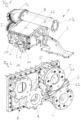
- FIG. 1 An exemplary embodiment of a temperature control device 1 according to the invention for temperature control of a fuel-air mixture is shown in Fig. 1 shown.
- a fuel-air mixture is supplied to an intake side of a compressor of a turbocharger, not shown, via a connection 13, a pipe connection and a connection 12 (these components are not part of the temperature control device 1).
- a temperature control device 1 for charge air could be designed identically. From the turbocharger, the compressed mixture is delivered to an inlet connection 2 via hoses or piping, not shown Temperature control device 1 is brought and leaves it via an output connection 3.
- the temperature control device 1 is designed in two stages and has a first temperature control branch 16 and a second temperature control branch 17. From the discharge connection 5, the temperature control medium reaches the supply connection 9 of the downstream temperature control branch for temperature control medium via a hose or piping, not shown, flows through a heat exchanger inside the housing and leaves the housing via the discharge connection 10. In a single-stage design, the downstream temperature control branch including the supply connection 9 and Discharge connection 10.
- a housing includes an interior space.
- the housing has an input connection 2 and an output connection 3 for a first temperature control branch for the mixture to be tempered and a supply connection 4 and a discharge connection 5 for temperature control medium.
- the supply connection 4 and the discharge connection 5 are arranged together on a cover 8 which forms the housing ( Fig. 2 ). In the exemplary embodiment shown, they are each designed in two parts, with the part 4', 5' closer to the cover 8 being formed in one piece with the cover 8 and the part further away from the cover 8 being detachably connected to the closer part 4', 5'.
- a second temperature control circuit is provided, which is connected downstream of the first temperature control circuit and has a supply connection 9 and a discharge connection 10 for temperature control agents.
- no bypass 6 is provided in this downstream temperature control circuit.
- a heat exchanger is arranged or formed in a known manner, via which a heat exchange takes place between the temperature control medium and charge air or mixture during operation of the temperature control device 1.
- the heat exchanger was not shown because it corresponds to the state of the art.
- a bypass 6 is arranged between the supply connection 4 and the discharge connection 5 for temperature control medium, via which temperature control medium can flow from the supply connection 4 to the discharge connection 5 without entering the heat exchanger.
- the bypass 6 here consists, for example, of two sections 61, 62 (cf. Fig. 3 ), whereby one of the two sections 61, 62 is formed in one piece with the supply connection 4 (more precisely: with the part which is further away from the cover 8) and the other of the two sections 61, 62 is formed in one piece with the discharge connection 5 ( more precisely: with that part which is further away from the cover 8).
- the bypass 6 is arranged outside the interior of the housing.
- the exemplary embodiment of the Fig. 4 shows a diaphragm 7 arranged interchangeably in the bypass 6, which is designed here in the form of a perforated plate.
- the number and/or size of the holes determine the free flow cross section of the orifice.
- the aperture 7 is arranged between the two sections 61, 62 and is sealed in a liquid-tight manner from them by seals 11.
- seals 11 Between the sections 61, 62 and the more distant parts of the supply connection 4 and the discharge connection 5 are connected again to the parts closer to the cover 8.
- a first exemplary embodiment of an internal combustion engine in the form of a reciprocating piston engine with a temperature control device 1 according to the invention is shown schematically in Fig. 5a shown.
- Mixture or compressed charge air compressed by a compressor of a turbocharger 14 is supplied to the temperature control device 1.
- the tempered mixture or the tempered charge air is supplied by the Temperature control device 1 is supplied to an engine block 15 (with a large number of piston-cylinder units, not shown, in which the combustion processes take place).
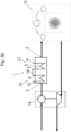
- Fig. 5b shows a further exemplary embodiment of an internal combustion engine in the form of a reciprocating piston engine with a temperature control device 1 according to the invention.
- the temperature control device 1 of Fig. 5b has a first temperature control branch 16 and a second temperature control branch 17.
- a temperature control medium is supplied via a supply connection 4 to a second temperature control branch 17, which has a bypass 6.
- the temperature control medium is conducted by means of a connecting line 18 from the discharge connection 5 of the second temperature control branch 17 to a serially looked up supply connection 9 of the first temperature control branch 16.
- the temperature control medium leaves the temperature control device 1 via the discharge connection 10.
Landscapes
- Engineering & Computer Science (AREA)
- Physics & Mathematics (AREA)
- Thermal Sciences (AREA)
- Mechanical Engineering (AREA)
- General Engineering & Computer Science (AREA)
- Chemical & Material Sciences (AREA)
- Combustion & Propulsion (AREA)
- Temperature-Responsive Valves (AREA)
Description
- Die Erfindung betrifft eine Temperiervorrichtung mit den Merkmalen des Oberbegriffs des Anspruchs 1 und eine Brennkraftmaschine mit wenigstens einer solchen Temperiervorrichtung.
- Gattungsgemäße Temperiervorrichtungen werden zumeist zum Kühlen von Ladeluft oder - im Falle gemischaufgeladener Brennkraftmaschinen - zum Kühlen eines Brennstoff-Luft-Gemisches eingesetzt. Es kann jedoch in Abhängigkeit von den Umgebungsbedingungen der Brennkraftmaschine durchaus erforderlich sein, die Ladeluft oder das Brennstoff-Luft-Gemisch mittels der Temperiervorrichtung zu erwärmen.
- Aus dem Stand der Technik bekannte Ausführungsformen gehen beispielweise aus der
US 2016/0273854 A1 , derJP 2013 079589 A US 2018/169433 A1 hervor. - Es kann notwendig sein, dem Wärmetauscher der Temperiervorrichtung nur einen Teil des im Einlasstrakt der Brennkraftmaschine vorhandenen Temperiermediumflusses zuzuführen (beispielsweise, aber nicht nur, bei einer zweistufigen Ausbildung des Temperiermediums). In solchen Fällen muss im Stand der Technik die Temperiervorrichtung mittels eines außerhalb der Temperiervorrichtung angeordneten und von der Temperiervorrichtung gesonderten Bypasses umgangen werden, was mit einer Vergrößerung des erforderlichen Bauraumes verbunden ist.
- Aufgabe der Erfindung ist die Bereitstellung einer gattungsgemäßen Temperiervorrichtung und einer Brennkraftmaschine mit einer solchen Temperiervorrichtung, bei welchen auf kompakte Art und Weise das Vorsehen eines Bypasses ermöglicht wird.
- Diese Aufgabe wird durch eine Temperiervorrichtung mit den Merkmalen des Anspruchs 1 und eine Brennkraftmaschine mit einer solchen Temperiervorrichtung gelöst. Vorteilhafte Ausführungsformen der Erfindung sind in den abhängigen Ansprüchen definiert.
- Eine erfindungsgemäße Temperiervorrichtung für Ladeluft oder ein Brennstoff-Luft-Gemisch einer Brennkraftmaschine, weist ein einen Innenraum umschließendes Gehäuse auf, welches zumindest einen Eingangsanschluss und zumindest einen Ausgangsanschluss für die zu temperierende Ladeluft oder das zu temperierende Gemisch und wenigstens einen Zufuhranschluss und wenigstens einen Abfuhranschluss für Temperiermedium aufweist, wobei im Innenraum des Gehäuses ein Wärmetauscher angeordnet oder ausgebildet ist, über welchen im Betrieb der Temperiervorrichtung ein Wärmetausch zwischen Temperiermedium und Ladeluft oder Gemisch stattfindet. Zwischen dem wenigstens einen Zufuhranschluss und dem wenigstens einen Abfuhranschluss für Temperiermedium ist (als baulicher Teil der Temperiervorrichtung) zumindest ein Bypass angeordnet, über welchen Temperiermedium vom wenigstens einen Zufuhranschluss zum wenigstens einen Abfuhranschluss strömen kann, ohne in den Wärmetauscher einzutreten.
- Bei der Erfindung ist also vorgesehen, dass der zumindest eine Bypass ein Teil der Temperiervorrichtung selbst ist und in diese baulich integriert ist. Damit ergibt sich eine äußerst kompakte Bauweise ohne das Erfordernis einer von der Temperiervorrichtung gesonderten Verschlauchung oder Verrohrung für den zumindest einen Bypass. Vom Gesamtstrom an Temperiermedium, der in den wenigstens einen Zufuhranschluss eintreten kann, wird innerhalb des wenigstens einen Zufuhranschlusses über den zumindest einen Bypass ein Teilstrom abgezweigt (wobei ein anderer Teilstrom zum Wärmetauscher strömt), strömt zum wenigstens einen Abfuhranschluss und verlässt gemeinsam mit einem vom Wärmetauscher kommenden Teilstrom die Temperiervorrichtung über den wenigstens einen Abfuhranschluss.
- Grundsätzlich könnte zwar vorgesehen sein, dass der zumindest eine Bypass innerhalb des Innenraumes des Gehäuses angeordnet ist, was im Vergleich zu einer von der Temperiervorrichtung gesonderten Verschlauchung oder Verrohrung für den zumindest einen Bypass immer noch eine kompaktere Bauweise darstellt. Ein noch kleiner dimensioniertes Gehäuse ist allerdings bei einem Ausführungsbeispiel der Erfindung möglich, wenn vorgesehen ist, dass der zumindest eine Bypass außerhalb des Innenraums des Gehäuses angeordnet ist.
- Wie groß der Anteil des über den zumindest einen Bypass strömenden Teilstroms relativ zu dem Gesamtstrom oder relativ zum in Richtung des Wärmetauschers strömenden Teilstroms ist, kann - wenn alle anderen Gegebenheiten der Temperiervorrichtung unverändert bleiben - über den freien Strömungsquerschnitt des zumindest einen Bypasses gewählt werden.
- Gemäß der Erfindung ist vorgesehen, dass im zumindest einen Bypass wenigstens eine Blende angeordnet ist. Der Anteil an über den zumindest einen Bypass strömenden Teilstrom kann in diesem Fall über den freien Strömungsquerschnitt der wenigstens einen Blende, welche den über den freien Strömungsquerschnitt des zumindest einen Bypasses darstellt, gewählt werden.
- Die Blende ist erfindungsgemäßen in Form eines Lochbleches ausgebildet.
- Es kann vorgesehen sein, dass die wenigstens eine Blende austauschbar im zumindest einen Bypass angeordnet ist. Dies eröffnet die Möglichkeit, für ein und dieselbe Temperiervorrichtung durch Wahl einer geeigneten Blende (wobei verschiedene Blenden einen verschiedenen freien Strömungsquerschnitt aufweisen können) einen gewünschten, über den zumindest einen Bypass strömenden Teilstrom zu wählen. Die Austauschbarkeit der wenigstens einen Blende kann beispielsweise so erfolgen, dass die wenigstens eine Blende in eine entsprechende Ausnehmung des zumindest einen Bypasses von außen einführbar ist.
- Gemäß der Erfindung ist vorgesehen, dass der zumindest eine Bypass aus wenigstens zwei Teilstücken besteht, wobei eines der wenigstens zwei Teilstücke einstückig mit dem wenigstens einen Zufuhranschluss ausgebildet ist und/oder eines der wenigstens zwei Teilstücke einstückig mit dem wenigstens einen Abfuhranschluss ausgebildet ist. Dies ergibt eine besonders kompakte Bauform. Ist beispielsweise eine austauschbare Blende vorgesehen, kann diese erfindungsgemäß zwischen den wenigstens zwei Teilstücken des zumindest einen Bypass angeordnet (vorzugsweise eingeklemmt) werden. Zum Austausch der Blende können die wenigstens zwei Teilstücke vom Gehäuse gelöst werden, die Blende wird ausgetauscht und anschließend über die wenigstens zwei Teilstücke am Gehäuse befestigt.
- Bei einem Ausführungsbeispiel der Erfindung ist vorgesehen, dass zumindest der wenigstens eine Zufuhranschluss und/oder der wenigstens eine Abfuhranschluss und/oder der zumindest eine Bypass gemeinsam an einem das Gehäuse mitbildenden Deckel angeordnet sind. Dies ermöglicht eine Ausbildung, bei welcher die restliche Temperiervorrichtung nach dem Stand der Technik ausgebildet werden kann.
- Der wenigstens eine Zufuhranschluss und/oder der wenigstens eine Abfuhranschluss können bzw. kann einteilig oder mehrteilig ausgebildet sein. Im Falle einer mehrteiligen Ausbildung kann vorgesehen sein, dass der zumindest eine Bypass in Bezug auf den wenigstens einen Zufuhranschluss und/oder den wenigstens einen Abfuhranschluss vollständig an einem einzigen Teil angeordnet ist oder an zumindest zwei Teilen (z. B. Unterseite des zumindest einen Bypass an einem Teil und Oberseite des zumindest einen Bypass an anderem Teil) angeordnet ist.
- Bei einem Ausführungsbeispiel der Erfindung ist vorgesehen, dass zumindest ein Teil des wenigstens einen Zufuhranschlusses und/oder ein Teil des wenigstens einen Abfuhranschlusses einstückig mit dem Deckel ausgebildet sind bzw. ist, wobei bevorzugt vorgesehen ist, dass der Deckel als Gussteil (aus Metall oder Kunststoff) ausgebildet ist. Dies stellt eine einfache Herstellungsmöglichkeit dar.
- Es kann vorgesehen sein, dass die Temperiervorrichtung nur einstufig ausgebildet ist. Bei einem Ausführungsbeispiel der Erfindung ist allerdings vorgesehen, dass die Temperiervorrichtung zweistufig ausgebildet ist und einen ersten und einen zweiten Temperierzweig aufweist. In diesem Fall kann es genügen, wenn der zumindest eine Bypass gemäß der Erfindung nur bei einem der Temperierzweige vorgesehen ist. Sind der erste und der zweite Temperierzweig strömungstechnisch in Bezug auf das Temperiermedium seriell geschaltet, kann der zumindest eine Bypass in Bezug auf die Strömungsrichtung des Temperiermediums bei dem vorgeschalteten Temperierzweig vorgesehen sein. So kann ein für den vorgeschalteten Temperierzweig benötigter, niedrigerer Temperiermediumfluss (im Vergleich zum nachgeschalteten Temperierzweig) erreicht werden, indem ein Teilstrom über den Bypass strömt.
- Bevorzugt können seriell geschaltene Temperierzweige vorgesehen sein, wobei das Temperiermedium die Temperierzweige entgegen einer Strömungsrichtung der zu kühlenden Ladeluft oder des zu kühlenden Gemisches durchläuft.
- Als Temperiermedium kommt in bekannter Weise bevorzugt eine Flüssigkeit, insbesondere ggf. mit Zusätzen versehenes Wasser, zum Einsatz.
- Das in der erfindungsgemäßen Temperiervorrichtung temperierte Temperiermedium kann zusätzlich dazu verwendet werden, die Brennkraftmaschine selbst und/oder einen Schmiermittelkreislauf (z. B. Ölkreislauf) der Brennkraftmaschine zu temperieren.
- Der wenigstens eine Zufuhranschluss und/oder der wenigstens eine Abfuhranschluss können bzw. kann in bekannter Weise mit einer Verschlauchung oder einem Rohr verbunden werden. Beispielsweise kann eine Ausbildung als Flansch vorgesehen sein. Andere Ausbildungen aus dem Stand der Technik sind einsetzbar.
- Die erfindungsgemäße Brennkraftmaschine ist bevorzugt in Form einer Hubkolbenmaschine ausgebildet.
- Die erfindungsgemäße Brennkraftmaschine ist bevorzugt in Form einer stationären Brennkraftmaschine ausgebildet. Bevorzugt ist sie mit einem elektrischen Generator mechanisch zu einem Genset gekoppelt.
- Ausführungsbeispiele der Erfindung werden anhand der Figuren diskutiert. Es zeigen:
- Fig. 1
- eine perspektivische Ansicht einer erfindungsgemäßen Temperiervorrichtung
- Fig. 2
- einen Deckel des Gehäuses der in
Fig. 1 dargestellten Tem periervorrichtung - Fig. 3
- eine Explosionsdarstellung zur
Fig. 2 - Fig. 4
- ein Detail zu einer Variante der
Fig. 3 in Explosionsdarstellung - Fig. 5a, b
- schematische Darstellungen von Ausführungsbeispielen einer erfindungsgemäßen Brennkraftmaschine
- Ein Ausführungsbeispiel einer erfindungsgemäßen Temperiervorrichtung 1 zum Temperieren eines Brennstoff-Luft-Gemisches ist in
Fig. 1 gezeigt. Über einen Anschluss 13, eine Rohrverbindung und einen Anschluss 12 (diese Komponenten sind nicht Teil der Temperiervorrichtung 1) wird einer Ansaugseite eines Kompressors eines nicht dargestellten Turboladers ein Brennstoff-Luft-Gemisch zugeführt. Eine Temperiervorrichtung 1 für Ladeluft könnte identisch ausgebildet sein. Vom Turbolader wird das komprimierte Gemisch über eine nicht dargestellte Verschlauchung oder Verrohrung zu einem Eingangsanschluss 2 der Temperiervorrichtung 1 gebracht und verlässt diese über einen Ausgangsanschluss 3. - Die Temperiervorrichtung 1 ist in diesem Ausführungsbeispiel zweistufig ausgebildet und weist einen ersten Temperierzweig 16 und einen zweiten Temperierzweig 17 auf. Vom Abfuhranschluss 5 gelangt das Temperiermedium über eine nicht dargestellte Verschlauchung oder Verrohrung zum Zufuhranschluss 9 des nachgeschalteten Temperierzweigs für Temperiermedium, durchströmt einen Wärmetauscher im Inneren des Gehäuses und verlässt das Gehäuse über den Abfuhranschluss 10. Bei einer einstufigen Ausbildung entfällt der nachgeschaltete Temperierzweig samt Zufuhranschluss 9 und Abfuhranschluss 10.
- Ein Gehäuse schließt einen Innenraum ein. Das Gehäuse weist einen Eingangsanschluss 2 und einen Ausgangsanschluss 3 für einen ersten Temperierzweig für das zu temperierende Gemisch und einen Zufuhranschluss 4 und einen Abfuhranschluss 5 für Temperiermedium auf. Der Zufuhranschluss 4 und der Abfuhranschluss 5 sind gemeinsam an einem das Gehäuse mitbildenden Deckel 8 angeordnet (
Fig. 2 ). Sie sind im gezeigten Ausführungsbeispiel jeweils zweiteilig ausgebildet, wobei der dem Deckel 8 nähere Teil 4`, 5' jeweils einstückig mit dem Deckel 8 ausgebildet ist und der vom Deckel 8 entferntere Teil jeweils lösbar mit dem näheren Teil 4`, 5' verbunden ist. - Es ist in diesem Ausführungsbeispiel ein zweiter Temperierkreis vorgesehen, welcher dem ersten Temperierkreis nachgeschaltet ist und einen Zufuhranschluss 9 und einen Abfuhranschluss 10 für Temperiermittel aufweist. In diesem nachgeschalteten Temperierkreis ist in diesem Ausführungsbeispiel kein Bypass 6 vorgesehen.
- Im Innenraum des Gehäuses ist in bekannter Weise ein Wärmetauscher angeordnet oder ausgebildet, über welchen im Betrieb der Temperiervorrichtung 1 ein Wärmetausch zwischen Temperiermedium und Ladeluft oder Gemisch stattfindet.
- Auf eine Darstellung des Wärmetauschers wurde verzichtet, da er dem Stand der Technik entsprechen kann.
- Zwischen dem Zufuhranschluss 4 und dem Abfuhranschluss 5 für Temperiermedium ist ein Bypass 6 angeordnet, über welchen Temperiermedium vom Zufuhranschluss 4 zum Abfuhranschluss 5 strömen kann, ohne in den Wärmetauscher einzutreten. Der Bypass 6 besteht hier beispielhaft aus zwei Teilstücken 61, 62 (vgl.
Fig. 3 ), wobei eines der zwei Teilstücke 61, 62 einstückig mit dem Zufuhranschluss 4 ausgebildet ist (genauer: mit jenem Teil, welches sich weiter weg vom Deckel 8 befindet) und das andere der zwei Teilstücke 61, 62 einstückig mit dem Abfuhranschluss 5 ausgebildet ist (genauer: mit jenem Teil, welches sich weiter weg vom Deckel 8 befindet). Der Bypass 6 ist außerhalb des Innenraums des Gehäuses angeordnet. - Das Ausführungsbeispiel der
Fig. 4 zeigt eine austauschbar im Bypass 6 angeordnete Blende 7, welche hier in Form eines Lochbleches ausgebildet ist. Die Anzahl und/oder Größe der Löcher bestimmen den freien Strömungsquerschnitt der Blende. - Die Blende 7 ist zwischen den zwei Teilstücken 61, 62 angeordnet und gegenüber diesen durch Dichtungen 11 flüssigkeitsdicht abgedichtet. Zum Wechseln der Blende 7 werden die vom Deckel 8 weiter entfernten Teile des Zufuhranschlusses 4 und des Abfuhranschlusses 5 von den dem Deckel 8 näheren Teilen entfernt, die Blende 7 wird samt Dichtungen 11 zwischen den Teilstücken 61, 62 angeordnet und die weiter entfernten Teile des Zufuhranschlusses 4 und des Abfuhranschlusses 5 werden wieder mit den dem Deckel 8 näheren Teilen verbunden.
- Ein erstes Ausführungsbeispiel einer Brennkraftmaschine in Form einer Hubkolbenmaschine mit einer erfindungsgemäßen Temperiervorrichtung 1 ist schematisch in
Fig. 5a gezeigt. Von einem Kompressor eines Turboladers 14 verdichtetes Gemisch oder verdichtete Ladeluft wird der Temperiervorrichtung 1 zugeführt. Das temperierte Gemisch oder die temperierte Ladeluft wird von der Temperiervorrichtung 1 einem Motorblock 15 (mit einer Vielzahl von nicht dargestellten Kolben-Zylinder-Einheiten, in welchen die Verbrennungsprozesse stattfinden) zugeführt. -
Fig. 5b . zeigt ein weiteres Ausführungsbeispiel einer Brennkraftmaschine in Form einer Hubkolbenmaschine mit einer erfindungsgemäßen Temperiervorrichtung 1. Die Temperiervorrichtung 1 derFig. 5b weist dabei einen ersten Temperierzweig 16 und einen zweiten Temperierzweig 17 auf. Ein Temperiermedium wird dabei über einen Zufuhranschlusses 4 einer zweiten Temperierzweig 17 zugeführt, welcher über einen Bypass 6 verfügt. Nach durchlaufen des zweiten Temperierzweiges 17 wird das Temperiermedium mittels einer Verbindungsleitung 18 vom Abfuhranschlusses 5 des zweiten Temperierzweiges 17 an einen seriell nachgeschlagenen Zufuhranschluss 9 des ersten Temperierzweiges 16 geleitet. Nach durchlaufen des (seriell nachgeschlagenem) ersten Temperierzweiges 16 verlässt das Temperiermedium die Temperiervorrichtung 1 über den Abfuhranschluss 10. -
- 1
- Temperiervorrichtung
- 2
- Eingangsanschluss für Ladeluft oder Brennstoff-Luft-Gemisch
- 3
- Ausgangsanschluss für Ladeluft oder Brennstoff-Luft-Gemisch
- 4, 4'
- Zufuhranschluss für Temperiermedium
- 5, 5'
- Abfuhranschluss für Temperiermedium
- 6
- Bypass für Temperiermedium
61 erstes Teilstück des Bypasses
62 zweites Teilstück des Bypasses - 7
- Blende im Bypass
- 8
- Deckel des Gehäuses
- 9
- Zufuhranschluss eines nachgeschalteten Temperierzweigs für Temperiermedium
- 10
- Abfuhranschluss eines nachgeschalteten Temperierzweigs für Temperiermedium
- 11
- Dichtung für Blende
- 12
- Anschluss für Ansaugseite eines Kompressors eines Turboladers
- 13
- Anschluss
- 14
- Turbolader
- 15
- Motorblock
- 16
- erster Temperierzweig
- 17
- zweiter Temperierzweig
- 18
- Verbindungsleitung
Claims (8)
- Temperiervorrichtung (1) für Ladeluft oder ein Brennstoff-Luft-Gemisch einer Brennkraftmaschine, mit einem einen Innenraum umschließenden Gehäuse, welches zumindest einen Eingangsanschluss (2) und zumindest einen Ausgangsanschluss (3) für die zu temperierende Ladeluft oder das zu temperierende Gemisch und wenigstens einen Zufuhranschluss (4) und wenigstens einen Abfuhranschluss (5) für Temperiermedium aufweist, wobei im Innenraum des Gehäuses ein Wärmetauscher angeordnet oder ausgebildet ist, über welchen im Betrieb der Temperiervorrichtung (1) ein Wärmetausch zwischen Temperiermedium und Ladeluft oder Gemisch stattfindet, dadurch gekennzeichnet, dass zwischen dem wenigstens einen Zufuhranschluss (4) und dem wenigstens einen Abfuhranschluss (5) für Temperiermedium zumindest ein Bypass (6) angeordnet ist, über welchen Temperiermedium vom wenigstens einen Zufuhranschluss (4) zum wenigstens einen Abfuhranschluss (5) strömen kann, ohne in den Wärmetauscher einzutreten, wobei- im zumindest einen Bypass (6) wenigstens eine Blende (7) angeordnet ist,- die die wenigstens eine Blende (7) in Form eines Lochbleches ist,- die Anzahl und/oder die Größe der Löcher den freien Strömungsquerschnitt der Blende bestimmen- der zumindest eine Bypass (6) aus wenigstens zwei Teilstücken (61, 62) besteht,- eines der wenigstens zwei Teilstücke (61, 62) einstückig mit dem wenigstens einen Zufuhranschluss (4) ausgebildet ist und/oder eines der wenigstens zwei Teilstücke (61, 62) einstückig mit dem wenigstens einen Abfuhranschluss (5) ausgebildet ist sowie- die wenigstens eine Blende (7) zwischen den wenigstens zwei Teilstücken (61, 62) des Bypasses (6) angeordnet ist.
- Temperiervorrichtung nach Anspruch 1, wobei der zumindest eine Bypass (6) außerhalb des Innenraums des Gehäuses angeordnet ist.
- Temperiervorrichtung nach wenigstens einem der vorangehenden Ansprüche, wobei die wenigstens eine Blende (7) austauschbar im zumindest einen Bypass (6) angeordnet ist.
- Temperiervorrichtung nach wenigstens einem der vorangehenden Ansprüche, wobei die wenigstens eine Blende (7) mit zumindest einer Dichtung (11) zwischen den wenigstens zwei Teilstücken (61, 62) des Bypasses (6) angeordnet ist.
- Temperiervorrichtung nach wenigstens einem der vorangehenden Ansprüche, wobei zumindest der wenigstens eine Zufuhranschluss (4) und/oder der wenigstens eine Abfuhranschluss (5) und/oder der zumindest eine Bypass (6) gemeinsam an einem das Gehäuse mitbildenden Deckel (8) angeordnet sind.
- Temperiervorrichtung nach dem vorangehenden Anspruch, wobei zumindest ein Teil des wenigstens einen Zufuhranschlusses (4) und/oder ein Teil des wenigstens einen Abfuhranschlusses (5) einstückig mit dem Deckel (8) ausgebildet sind bzw. ist, wobei bevorzugt vorgesehen ist, dass der Deckel (8) als Gussteil ausgebildet ist.
- Temperiervorrichtung nach wenigstens einem der vorangehenden Ansprüche, wobei die Temperiervorrichtung (1) zweistufig ausgebildet ist und einen ersten und einen zweiten Temperierzweig aufweist.
- Brennkraftmaschine, vorzugsweise Hubkolbenmaschine, mit wenigstens einer Temperiervorrichtung (1) nach wenigstens einem der vorangehenden Ansprüche.
Applications Claiming Priority (1)
| Application Number | Priority Date | Filing Date | Title |
|---|---|---|---|
| PCT/AT2019/060112 WO2020198766A1 (de) | 2019-04-03 | 2019-04-03 | Temperiervorrichtung und brennkraftmaschine mit einer solchen |
Publications (2)
| Publication Number | Publication Date |
|---|---|
| EP3947934A1 EP3947934A1 (de) | 2022-02-09 |
| EP3947934B1 true EP3947934B1 (de) | 2024-03-06 |
Family
ID=66217642
Family Applications (1)
| Application Number | Title | Priority Date | Filing Date |
|---|---|---|---|
| EP19718055.7A Active EP3947934B1 (de) | 2019-04-03 | 2019-04-03 | Temperiervorrichtung und brennkraftmaschine mit einer solchen |
Country Status (2)
| Country | Link |
|---|---|
| EP (1) | EP3947934B1 (de) |
| WO (1) | WO2020198766A1 (de) |
Family Cites Families (4)
| Publication number | Priority date | Publication date | Assignee | Title |
|---|---|---|---|---|
| US20060272621A1 (en) * | 2005-06-03 | 2006-12-07 | Acuna Henry T Sr | Cold air induction system, apparatus and method |
| JP2013079589A (ja) * | 2011-10-03 | 2013-05-02 | Daihatsu Diesel Mfg Co Ltd | 内燃機関用の空気冷却器 |
| US10690421B2 (en) * | 2012-03-28 | 2020-06-23 | Modine Manufacturing Company | Heat exchanger and method of cooling a flow of heated air |
| FR3008175A1 (fr) * | 2013-07-04 | 2015-01-09 | Valeo Systemes Thermiques | Dispositif de regulation de la circulation d'un liquide de refroidissement pour un echangeur de chaleur, en particulier refroidisseur d'air de suralimentation de moteur de vehicule automobile |
-
2019
- 2019-04-03 WO PCT/AT2019/060112 patent/WO2020198766A1/de not_active Ceased
- 2019-04-03 EP EP19718055.7A patent/EP3947934B1/de active Active
Also Published As
| Publication number | Publication date |
|---|---|
| EP3947934A1 (de) | 2022-02-09 |
| WO2020198766A1 (de) | 2020-10-08 |
Similar Documents
| Publication | Publication Date | Title |
|---|---|---|
| DE102009050016A1 (de) | Wärmeübertragereinheit | |
| EP2016259B1 (de) | Ölmodul mit integriertem kühlwasserkanal | |
| DE20013534U1 (de) | Vorrichtung zur Rückführung von Gas an einem Verbrennungsmotor | |
| DE19853455A1 (de) | Kühleranordnung für eine aufgeladene Brennkraftmaschine mit Abgasrückführung | |
| DE102008036755A1 (de) | Schaltschrank | |
| DE102020216288A1 (de) | Ölmodul | |
| DE1503398A1 (de) | Motorkompressor in gekapselter Ausfuehrung | |
| EP1995463B1 (de) | Mehrstufige Verdichtereinheit mit Kühleinrichtung | |
| DE102019213191A1 (de) | Batteriesystem, insbesondere zum Antreiben eines Fahrzeuges | |
| DE102017219433A1 (de) | Wärmeübertrager für einen Verbrennungsmotor | |
| EP3947934B1 (de) | Temperiervorrichtung und brennkraftmaschine mit einer solchen | |
| EP2466089A2 (de) | Ladeluftkühler | |
| DE102009022919A1 (de) | Wärmeübertragereinheit | |
| EP2532848B1 (de) | Filter- und Kühlvorrichtung | |
| DE102010016580A1 (de) | Turboladeraufbau für eine Brennkraftmaschine | |
| EP2161428A1 (de) | Ladeluftkühler, insbesondere für Grossmotoren | |
| DE202004016183U1 (de) | Wärmetauscher für einen Verbrennungsmotor | |
| DE102010008656B4 (de) | Abscheidevorrichtung | |
| DE202004011911U1 (de) | Vorrichtung zum Kühlen und Filtern eines kreislaufgeführten Fluids sowie zugehöriges Gehäuse | |
| DE102021002332A1 (de) | Kühlkreislauf für ein Kraftfahrzeug, insbesondere für einen Kraftwagen | |
| DE102021212202A1 (de) | Drosselklappenstellereinheit, Brennstoffzellensystem mit einer derartigen Drosselklappenstellereinheit und Kraftfahrzeug mit einem derartigen Brennstoffzellensystem | |
| DE102016010906B3 (de) | Kühlmittelkühler für ein Kraftfahrzeug | |
| DE102023123784A1 (de) | Kompressor mit Luftführung durch das Gehäuse | |
| DE2500046A1 (de) | Durchflussregelventil | |
| DE102023201854A1 (de) | Wärmeübertrager |
Legal Events
| Date | Code | Title | Description |
|---|---|---|---|
| STAA | Information on the status of an ep patent application or granted ep patent |
Free format text: STATUS: UNKNOWN |
|
| STAA | Information on the status of an ep patent application or granted ep patent |
Free format text: STATUS: THE INTERNATIONAL PUBLICATION HAS BEEN MADE |
|
| PUAI | Public reference made under article 153(3) epc to a published international application that has entered the european phase |
Free format text: ORIGINAL CODE: 0009012 |
|
| STAA | Information on the status of an ep patent application or granted ep patent |
Free format text: STATUS: REQUEST FOR EXAMINATION WAS MADE |
|
| 17P | Request for examination filed |
Effective date: 20210923 |
|
| AK | Designated contracting states |
Kind code of ref document: A1 Designated state(s): AL AT BE BG CH CY CZ DE DK EE ES FI FR GB GR HR HU IE IS IT LI LT LU LV MC MK MT NL NO PL PT RO RS SE SI SK SM TR |
|
| STAA | Information on the status of an ep patent application or granted ep patent |
Free format text: STATUS: EXAMINATION IS IN PROGRESS |
|
| 17Q | First examination report despatched |
Effective date: 20220412 |
|
| DAV | Request for validation of the european patent (deleted) | ||
| DAX | Request for extension of the european patent (deleted) | ||
| P01 | Opt-out of the competence of the unified patent court (upc) registered |
Effective date: 20230614 |
|
| GRAP | Despatch of communication of intention to grant a patent |
Free format text: ORIGINAL CODE: EPIDOSNIGR1 |
|
| STAA | Information on the status of an ep patent application or granted ep patent |
Free format text: STATUS: GRANT OF PATENT IS INTENDED |
|
| INTG | Intention to grant announced |
Effective date: 20231110 |
|
| GRAS | Grant fee paid |
Free format text: ORIGINAL CODE: EPIDOSNIGR3 |
|
| GRAA | (expected) grant |
Free format text: ORIGINAL CODE: 0009210 |
|
| STAA | Information on the status of an ep patent application or granted ep patent |
Free format text: STATUS: THE PATENT HAS BEEN GRANTED |
|
| AK | Designated contracting states |
Kind code of ref document: B1 Designated state(s): AL AT BE BG CH CY CZ DE DK EE ES FI FR GB GR HR HU IE IS IT LI LT LU LV MC MK MT NL NO PL PT RO RS SE SI SK SM TR |
|
| REG | Reference to a national code |
Ref country code: CH Ref legal event code: EP |
|
| REG | Reference to a national code |
Ref country code: DE Ref legal event code: R096 Ref document number: 502019010740 Country of ref document: DE |
|
| REG | Reference to a national code |
Ref country code: IE Ref legal event code: FG4D Free format text: LANGUAGE OF EP DOCUMENT: GERMAN |
|
| REG | Reference to a national code |
Ref country code: LT Ref legal event code: MG9D |
|
| PG25 | Lapsed in a contracting state [announced via postgrant information from national office to epo] |
Ref country code: LT Free format text: LAPSE BECAUSE OF FAILURE TO SUBMIT A TRANSLATION OF THE DESCRIPTION OR TO PAY THE FEE WITHIN THE PRESCRIBED TIME-LIMIT Effective date: 20240306 |
|
| REG | Reference to a national code |
Ref country code: NL Ref legal event code: MP Effective date: 20240306 |
|
| PG25 | Lapsed in a contracting state [announced via postgrant information from national office to epo] |
Ref country code: GR Free format text: LAPSE BECAUSE OF FAILURE TO SUBMIT A TRANSLATION OF THE DESCRIPTION OR TO PAY THE FEE WITHIN THE PRESCRIBED TIME-LIMIT Effective date: 20240607 |
|
| PG25 | Lapsed in a contracting state [announced via postgrant information from national office to epo] |
Ref country code: RS Free format text: LAPSE BECAUSE OF FAILURE TO SUBMIT A TRANSLATION OF THE DESCRIPTION OR TO PAY THE FEE WITHIN THE PRESCRIBED TIME-LIMIT Effective date: 20240606 Ref country code: HR Free format text: LAPSE BECAUSE OF FAILURE TO SUBMIT A TRANSLATION OF THE DESCRIPTION OR TO PAY THE FEE WITHIN THE PRESCRIBED TIME-LIMIT Effective date: 20240306 |
|
| PG25 | Lapsed in a contracting state [announced via postgrant information from national office to epo] |
Ref country code: ES Free format text: LAPSE BECAUSE OF FAILURE TO SUBMIT A TRANSLATION OF THE DESCRIPTION OR TO PAY THE FEE WITHIN THE PRESCRIBED TIME-LIMIT Effective date: 20240306 |
|
| PG25 | Lapsed in a contracting state [announced via postgrant information from national office to epo] |
Ref country code: RS Free format text: LAPSE BECAUSE OF FAILURE TO SUBMIT A TRANSLATION OF THE DESCRIPTION OR TO PAY THE FEE WITHIN THE PRESCRIBED TIME-LIMIT Effective date: 20240606 Ref country code: NO Free format text: LAPSE BECAUSE OF FAILURE TO SUBMIT A TRANSLATION OF THE DESCRIPTION OR TO PAY THE FEE WITHIN THE PRESCRIBED TIME-LIMIT Effective date: 20240606 Ref country code: LT Free format text: LAPSE BECAUSE OF FAILURE TO SUBMIT A TRANSLATION OF THE DESCRIPTION OR TO PAY THE FEE WITHIN THE PRESCRIBED TIME-LIMIT Effective date: 20240306 Ref country code: HR Free format text: LAPSE BECAUSE OF FAILURE TO SUBMIT A TRANSLATION OF THE DESCRIPTION OR TO PAY THE FEE WITHIN THE PRESCRIBED TIME-LIMIT Effective date: 20240306 Ref country code: GR Free format text: LAPSE BECAUSE OF FAILURE TO SUBMIT A TRANSLATION OF THE DESCRIPTION OR TO PAY THE FEE WITHIN THE PRESCRIBED TIME-LIMIT Effective date: 20240607 Ref country code: FI Free format text: LAPSE BECAUSE OF FAILURE TO SUBMIT A TRANSLATION OF THE DESCRIPTION OR TO PAY THE FEE WITHIN THE PRESCRIBED TIME-LIMIT Effective date: 20240306 Ref country code: ES Free format text: LAPSE BECAUSE OF FAILURE TO SUBMIT A TRANSLATION OF THE DESCRIPTION OR TO PAY THE FEE WITHIN THE PRESCRIBED TIME-LIMIT Effective date: 20240306 Ref country code: BG Free format text: LAPSE BECAUSE OF FAILURE TO SUBMIT A TRANSLATION OF THE DESCRIPTION OR TO PAY THE FEE WITHIN THE PRESCRIBED TIME-LIMIT Effective date: 20240306 |
|
| PG25 | Lapsed in a contracting state [announced via postgrant information from national office to epo] |
Ref country code: SE Free format text: LAPSE BECAUSE OF FAILURE TO SUBMIT A TRANSLATION OF THE DESCRIPTION OR TO PAY THE FEE WITHIN THE PRESCRIBED TIME-LIMIT Effective date: 20240306 Ref country code: LV Free format text: LAPSE BECAUSE OF FAILURE TO SUBMIT A TRANSLATION OF THE DESCRIPTION OR TO PAY THE FEE WITHIN THE PRESCRIBED TIME-LIMIT Effective date: 20240306 |
|
| PG25 | Lapsed in a contracting state [announced via postgrant information from national office to epo] |
Ref country code: NL Free format text: LAPSE BECAUSE OF FAILURE TO SUBMIT A TRANSLATION OF THE DESCRIPTION OR TO PAY THE FEE WITHIN THE PRESCRIBED TIME-LIMIT Effective date: 20240306 |
|
| PG25 | Lapsed in a contracting state [announced via postgrant information from national office to epo] |
Ref country code: NL Free format text: LAPSE BECAUSE OF FAILURE TO SUBMIT A TRANSLATION OF THE DESCRIPTION OR TO PAY THE FEE WITHIN THE PRESCRIBED TIME-LIMIT Effective date: 20240306 |
|
| PG25 | Lapsed in a contracting state [announced via postgrant information from national office to epo] |
Ref country code: IS Free format text: LAPSE BECAUSE OF FAILURE TO SUBMIT A TRANSLATION OF THE DESCRIPTION OR TO PAY THE FEE WITHIN THE PRESCRIBED TIME-LIMIT Effective date: 20240706 |
|
| PG25 | Lapsed in a contracting state [announced via postgrant information from national office to epo] |
Ref country code: SM Free format text: LAPSE BECAUSE OF FAILURE TO SUBMIT A TRANSLATION OF THE DESCRIPTION OR TO PAY THE FEE WITHIN THE PRESCRIBED TIME-LIMIT Effective date: 20240306 Ref country code: PT Free format text: LAPSE BECAUSE OF FAILURE TO SUBMIT A TRANSLATION OF THE DESCRIPTION OR TO PAY THE FEE WITHIN THE PRESCRIBED TIME-LIMIT Effective date: 20240708 |
|
| PG25 | Lapsed in a contracting state [announced via postgrant information from national office to epo] |
Ref country code: CZ Free format text: LAPSE BECAUSE OF FAILURE TO SUBMIT A TRANSLATION OF THE DESCRIPTION OR TO PAY THE FEE WITHIN THE PRESCRIBED TIME-LIMIT Effective date: 20240306 Ref country code: EE Free format text: LAPSE BECAUSE OF FAILURE TO SUBMIT A TRANSLATION OF THE DESCRIPTION OR TO PAY THE FEE WITHIN THE PRESCRIBED TIME-LIMIT Effective date: 20240306 |
|
| PG25 | Lapsed in a contracting state [announced via postgrant information from national office to epo] |
Ref country code: PL Free format text: LAPSE BECAUSE OF FAILURE TO SUBMIT A TRANSLATION OF THE DESCRIPTION OR TO PAY THE FEE WITHIN THE PRESCRIBED TIME-LIMIT Effective date: 20240306 |
|
| PG25 | Lapsed in a contracting state [announced via postgrant information from national office to epo] |
Ref country code: SK Free format text: LAPSE BECAUSE OF FAILURE TO SUBMIT A TRANSLATION OF THE DESCRIPTION OR TO PAY THE FEE WITHIN THE PRESCRIBED TIME-LIMIT Effective date: 20240306 |
|
| PG25 | Lapsed in a contracting state [announced via postgrant information from national office to epo] |
Ref country code: SM Free format text: LAPSE BECAUSE OF FAILURE TO SUBMIT A TRANSLATION OF THE DESCRIPTION OR TO PAY THE FEE WITHIN THE PRESCRIBED TIME-LIMIT Effective date: 20240306 Ref country code: SK Free format text: LAPSE BECAUSE OF FAILURE TO SUBMIT A TRANSLATION OF THE DESCRIPTION OR TO PAY THE FEE WITHIN THE PRESCRIBED TIME-LIMIT Effective date: 20240306 Ref country code: RO Free format text: LAPSE BECAUSE OF FAILURE TO SUBMIT A TRANSLATION OF THE DESCRIPTION OR TO PAY THE FEE WITHIN THE PRESCRIBED TIME-LIMIT Effective date: 20240306 Ref country code: PT Free format text: LAPSE BECAUSE OF FAILURE TO SUBMIT A TRANSLATION OF THE DESCRIPTION OR TO PAY THE FEE WITHIN THE PRESCRIBED TIME-LIMIT Effective date: 20240708 Ref country code: PL Free format text: LAPSE BECAUSE OF FAILURE TO SUBMIT A TRANSLATION OF THE DESCRIPTION OR TO PAY THE FEE WITHIN THE PRESCRIBED TIME-LIMIT Effective date: 20240306 Ref country code: IS Free format text: LAPSE BECAUSE OF FAILURE TO SUBMIT A TRANSLATION OF THE DESCRIPTION OR TO PAY THE FEE WITHIN THE PRESCRIBED TIME-LIMIT Effective date: 20240706 Ref country code: EE Free format text: LAPSE BECAUSE OF FAILURE TO SUBMIT A TRANSLATION OF THE DESCRIPTION OR TO PAY THE FEE WITHIN THE PRESCRIBED TIME-LIMIT Effective date: 20240306 Ref country code: CZ Free format text: LAPSE BECAUSE OF FAILURE TO SUBMIT A TRANSLATION OF THE DESCRIPTION OR TO PAY THE FEE WITHIN THE PRESCRIBED TIME-LIMIT Effective date: 20240306 |
|
| REG | Reference to a national code |
Ref country code: CH Ref legal event code: PL |
|
| REG | Reference to a national code |
Ref country code: DE Ref legal event code: R097 Ref document number: 502019010740 Country of ref document: DE |
|
| PG25 | Lapsed in a contracting state [announced via postgrant information from national office to epo] |
Ref country code: LU Free format text: LAPSE BECAUSE OF NON-PAYMENT OF DUE FEES Effective date: 20240403 |
|
| REG | Reference to a national code |
Ref country code: BE Ref legal event code: MM Effective date: 20240430 |
|
| PG25 | Lapsed in a contracting state [announced via postgrant information from national office to epo] |
Ref country code: LU Free format text: LAPSE BECAUSE OF NON-PAYMENT OF DUE FEES Effective date: 20240403 |
|
| PG25 | Lapsed in a contracting state [announced via postgrant information from national office to epo] |
Ref country code: MC Free format text: LAPSE BECAUSE OF FAILURE TO SUBMIT A TRANSLATION OF THE DESCRIPTION OR TO PAY THE FEE WITHIN THE PRESCRIBED TIME-LIMIT Effective date: 20240306 |
|
| PLBE | No opposition filed within time limit |
Free format text: ORIGINAL CODE: 0009261 |
|
| STAA | Information on the status of an ep patent application or granted ep patent |
Free format text: STATUS: NO OPPOSITION FILED WITHIN TIME LIMIT |
|
| PG25 | Lapsed in a contracting state [announced via postgrant information from national office to epo] |
Ref country code: DK Free format text: LAPSE BECAUSE OF FAILURE TO SUBMIT A TRANSLATION OF THE DESCRIPTION OR TO PAY THE FEE WITHIN THE PRESCRIBED TIME-LIMIT Effective date: 20240306 |
|
| PG25 | Lapsed in a contracting state [announced via postgrant information from national office to epo] |
Ref country code: BE Free format text: LAPSE BECAUSE OF NON-PAYMENT OF DUE FEES Effective date: 20240430 |
|
| PG25 | Lapsed in a contracting state [announced via postgrant information from national office to epo] |
Ref country code: MC Free format text: LAPSE BECAUSE OF FAILURE TO SUBMIT A TRANSLATION OF THE DESCRIPTION OR TO PAY THE FEE WITHIN THE PRESCRIBED TIME-LIMIT Effective date: 20240306 Ref country code: DK Free format text: LAPSE BECAUSE OF FAILURE TO SUBMIT A TRANSLATION OF THE DESCRIPTION OR TO PAY THE FEE WITHIN THE PRESCRIBED TIME-LIMIT Effective date: 20240306 Ref country code: BE Free format text: LAPSE BECAUSE OF NON-PAYMENT OF DUE FEES Effective date: 20240430 Ref country code: CH Free format text: LAPSE BECAUSE OF NON-PAYMENT OF DUE FEES Effective date: 20240430 |
|
| 26N | No opposition filed |
Effective date: 20241209 |
|
| PG25 | Lapsed in a contracting state [announced via postgrant information from national office to epo] |
Ref country code: IE Free format text: LAPSE BECAUSE OF NON-PAYMENT OF DUE FEES Effective date: 20240403 |
|
| PG25 | Lapsed in a contracting state [announced via postgrant information from national office to epo] |
Ref country code: SI Free format text: LAPSE BECAUSE OF FAILURE TO SUBMIT A TRANSLATION OF THE DESCRIPTION OR TO PAY THE FEE WITHIN THE PRESCRIBED TIME-LIMIT Effective date: 20240306 |
|
| REG | Reference to a national code |
Ref country code: AT Ref legal event code: MM01 Ref document number: 1663722 Country of ref document: AT Kind code of ref document: T Effective date: 20240403 |
|
| PGFP | Annual fee paid to national office [announced via postgrant information from national office to epo] |
Ref country code: DE Payment date: 20250319 Year of fee payment: 7 |
|
| PG25 | Lapsed in a contracting state [announced via postgrant information from national office to epo] |
Ref country code: AT Free format text: LAPSE BECAUSE OF NON-PAYMENT OF DUE FEES Effective date: 20240403 |
|
| PG25 | Lapsed in a contracting state [announced via postgrant information from national office to epo] |
Ref country code: CY Free format text: LAPSE BECAUSE OF FAILURE TO SUBMIT A TRANSLATION OF THE DESCRIPTION OR TO PAY THE FEE WITHIN THE PRESCRIBED TIME-LIMIT; INVALID AB INITIO Effective date: 20190403 |
|
| PG25 | Lapsed in a contracting state [announced via postgrant information from national office to epo] |
Ref country code: HU Free format text: LAPSE BECAUSE OF FAILURE TO SUBMIT A TRANSLATION OF THE DESCRIPTION OR TO PAY THE FEE WITHIN THE PRESCRIBED TIME-LIMIT; INVALID AB INITIO Effective date: 20190403 |
|
| PG25 | Lapsed in a contracting state [announced via postgrant information from national office to epo] |
Ref country code: TR Free format text: LAPSE BECAUSE OF FAILURE TO SUBMIT A TRANSLATION OF THE DESCRIPTION OR TO PAY THE FEE WITHIN THE PRESCRIBED TIME-LIMIT Effective date: 20240306 |
|
| PGFP | Annual fee paid to national office [announced via postgrant information from national office to epo] |
Ref country code: GB Payment date: 20260319 Year of fee payment: 8 |
|
| PGFP | Annual fee paid to national office [announced via postgrant information from national office to epo] |
Ref country code: IT Payment date: 20260319 Year of fee payment: 8 |
|
| PGFP | Annual fee paid to national office [announced via postgrant information from national office to epo] |
Ref country code: FR Payment date: 20260320 Year of fee payment: 8 |