EP3947261B1 - Reaktor für endotherme hochtemperaturreaktionen - Google Patents
Reaktor für endotherme hochtemperaturreaktionen Download PDFInfo
- Publication number
- EP3947261B1 EP3947261B1 EP20716701.6A EP20716701A EP3947261B1 EP 3947261 B1 EP3947261 B1 EP 3947261B1 EP 20716701 A EP20716701 A EP 20716701A EP 3947261 B1 EP3947261 B1 EP 3947261B1
- Authority
- EP
- European Patent Office
- Prior art keywords
- reactor
- zone
- reaction zone
- reaction
- solids particles
- Prior art date
- Legal status (The legal status is an assumption and is not a legal conclusion. Google has not performed a legal analysis and makes no representation as to the accuracy of the status listed.)
- Active
Links
Images

Classifications
-
- B—PERFORMING OPERATIONS; TRANSPORTING
- B01—PHYSICAL OR CHEMICAL PROCESSES OR APPARATUS IN GENERAL
- B01J—CHEMICAL OR PHYSICAL PROCESSES, e.g. CATALYSIS OR COLLOID CHEMISTRY; THEIR RELEVANT APPARATUS
- B01J8/00—Chemical or physical processes in general, conducted in the presence of fluids and solid particles; Apparatus for such processes
- B01J8/08—Chemical or physical processes in general, conducted in the presence of fluids and solid particles; Apparatus for such processes with moving particles
- B01J8/12—Chemical or physical processes in general, conducted in the presence of fluids and solid particles; Apparatus for such processes with moving particles moved by gravity in a downward flow
-
- B—PERFORMING OPERATIONS; TRANSPORTING
- B01—PHYSICAL OR CHEMICAL PROCESSES OR APPARATUS IN GENERAL
- B01J—CHEMICAL OR PHYSICAL PROCESSES, e.g. CATALYSIS OR COLLOID CHEMISTRY; THEIR RELEVANT APPARATUS
- B01J8/00—Chemical or physical processes in general, conducted in the presence of fluids and solid particles; Apparatus for such processes
- B01J8/08—Chemical or physical processes in general, conducted in the presence of fluids and solid particles; Apparatus for such processes with moving particles
- B01J8/087—Heating or cooling the reactor
-
- B—PERFORMING OPERATIONS; TRANSPORTING
- B01—PHYSICAL OR CHEMICAL PROCESSES OR APPARATUS IN GENERAL
- B01J—CHEMICAL OR PHYSICAL PROCESSES, e.g. CATALYSIS OR COLLOID CHEMISTRY; THEIR RELEVANT APPARATUS
- B01J8/00—Chemical or physical processes in general, conducted in the presence of fluids and solid particles; Apparatus for such processes
- B01J8/08—Chemical or physical processes in general, conducted in the presence of fluids and solid particles; Apparatus for such processes with moving particles
- B01J8/12—Chemical or physical processes in general, conducted in the presence of fluids and solid particles; Apparatus for such processes with moving particles moved by gravity in a downward flow
- B01J8/125—Chemical or physical processes in general, conducted in the presence of fluids and solid particles; Apparatus for such processes with moving particles moved by gravity in a downward flow with multiple sections one above the other separated by distribution aids, e.g. reaction and regeneration sections
-
- C—CHEMISTRY; METALLURGY
- C01—INORGANIC CHEMISTRY
- C01B—NON-METALLIC ELEMENTS; COMPOUNDS THEREOF; METALLOIDS OR COMPOUNDS THEREOF NOT COVERED BY SUBCLASS C01C
- C01B3/00—Hydrogen; Gaseous mixtures containing hydrogen; Separation of hydrogen from mixtures containing it; Purification of hydrogen; Reversible storage of hydrogen
- C01B3/02—Production of hydrogen; Production of gaseous mixtures containing hydrogen
- C01B3/22—Production of hydrogen; Production of gaseous mixtures containing hydrogen by decomposition of gaseous or liquid organic compounds
- C01B3/24—Production of hydrogen; Production of gaseous mixtures containing hydrogen by decomposition of gaseous or liquid organic compounds of hydrocarbons
- C01B3/28—Production of hydrogen; Production of gaseous mixtures containing hydrogen by decomposition of gaseous or liquid organic compounds of hydrocarbons using moving solid particles, e.g. fluidised bed technique
-
- C—CHEMISTRY; METALLURGY
- C01—INORGANIC CHEMISTRY
- C01B—NON-METALLIC ELEMENTS; COMPOUNDS THEREOF; METALLOIDS OR COMPOUNDS THEREOF NOT COVERED BY SUBCLASS C01C
- C01B3/00—Hydrogen; Gaseous mixtures containing hydrogen; Separation of hydrogen from mixtures containing it; Purification of hydrogen; Reversible storage of hydrogen
- C01B3/02—Production of hydrogen; Production of gaseous mixtures containing hydrogen
- C01B3/32—Production of hydrogen; Production of gaseous mixtures containing hydrogen by reaction of gaseous or liquid organic compounds with gasifying agents, e.g. water, carbon dioxide or air
- C01B3/34—Production of hydrogen; Production of gaseous mixtures containing hydrogen by reaction of gaseous or liquid organic compounds with gasifying agents, e.g. water, carbon dioxide or air by reaction of hydrocarbons with gasifying agents
- C01B3/38—Production of hydrogen; Production of gaseous mixtures containing hydrogen by reaction of gaseous or liquid organic compounds with gasifying agents, e.g. water, carbon dioxide or air by reaction of hydrocarbons with gasifying agents using catalysts
- C01B3/42—Production of hydrogen; Production of gaseous mixtures containing hydrogen by reaction of gaseous or liquid organic compounds with gasifying agents, e.g. water, carbon dioxide or air by reaction of hydrocarbons with gasifying agents using catalysts using moving solid particles, e.g. fluidised bed technique
-
- B—PERFORMING OPERATIONS; TRANSPORTING
- B01—PHYSICAL OR CHEMICAL PROCESSES OR APPARATUS IN GENERAL
- B01J—CHEMICAL OR PHYSICAL PROCESSES, e.g. CATALYSIS OR COLLOID CHEMISTRY; THEIR RELEVANT APPARATUS
- B01J2208/00—Processes carried out in the presence of solid particles; Reactors therefor
- B01J2208/00008—Controlling the process
- B01J2208/00017—Controlling the temperature
- B01J2208/00389—Controlling the temperature using electric heating or cooling elements
- B01J2208/00398—Controlling the temperature using electric heating or cooling elements inside the reactor bed
-
- B—PERFORMING OPERATIONS; TRANSPORTING
- B01—PHYSICAL OR CHEMICAL PROCESSES OR APPARATUS IN GENERAL
- B01J—CHEMICAL OR PHYSICAL PROCESSES, e.g. CATALYSIS OR COLLOID CHEMISTRY; THEIR RELEVANT APPARATUS
- B01J2208/00—Processes carried out in the presence of solid particles; Reactors therefor
- B01J2208/00008—Controlling the process
- B01J2208/00017—Controlling the temperature
- B01J2208/0053—Controlling multiple zones along the direction of flow, e.g. pre-heating and after-cooling
-
- B—PERFORMING OPERATIONS; TRANSPORTING
- B01—PHYSICAL OR CHEMICAL PROCESSES OR APPARATUS IN GENERAL
- B01J—CHEMICAL OR PHYSICAL PROCESSES, e.g. CATALYSIS OR COLLOID CHEMISTRY; THEIR RELEVANT APPARATUS
- B01J2219/00—Chemical, physical or physico-chemical processes in general; Their relevant apparatus
- B01J2219/08—Processes employing the direct application of electric or wave energy, or particle radiation; Apparatus therefor
- B01J2219/0803—Processes employing the direct application of electric or wave energy, or particle radiation; Apparatus therefor employing electric or magnetic energy
- B01J2219/0805—Processes employing the direct application of electric or wave energy, or particle radiation; Apparatus therefor employing electric or magnetic energy giving rise to electric discharges
- B01J2219/0807—Processes employing the direct application of electric or wave energy, or particle radiation; Apparatus therefor employing electric or magnetic energy giving rise to electric discharges involving electrodes
- B01J2219/0809—Processes employing the direct application of electric or wave energy, or particle radiation; Apparatus therefor employing electric or magnetic energy giving rise to electric discharges involving electrodes employing two or more electrodes
-
- B—PERFORMING OPERATIONS; TRANSPORTING
- B01—PHYSICAL OR CHEMICAL PROCESSES OR APPARATUS IN GENERAL
- B01J—CHEMICAL OR PHYSICAL PROCESSES, e.g. CATALYSIS OR COLLOID CHEMISTRY; THEIR RELEVANT APPARATUS
- B01J2219/00—Chemical, physical or physico-chemical processes in general; Their relevant apparatus
- B01J2219/08—Processes employing the direct application of electric or wave energy, or particle radiation; Apparatus therefor
- B01J2219/0873—Materials to be treated
- B01J2219/0892—Materials to be treated involving catalytically active material
-
- B—PERFORMING OPERATIONS; TRANSPORTING
- B01—PHYSICAL OR CHEMICAL PROCESSES OR APPARATUS IN GENERAL
- B01J—CHEMICAL OR PHYSICAL PROCESSES, e.g. CATALYSIS OR COLLOID CHEMISTRY; THEIR RELEVANT APPARATUS
- B01J2219/00—Chemical, physical or physico-chemical processes in general; Their relevant apparatus
- B01J2219/19—Details relating to the geometry of the reactor
- B01J2219/194—Details relating to the geometry of the reactor round
- B01J2219/1941—Details relating to the geometry of the reactor round circular or disk-shaped
- B01J2219/1946—Details relating to the geometry of the reactor round circular or disk-shaped conical
-
- C—CHEMISTRY; METALLURGY
- C01—INORGANIC CHEMISTRY
- C01B—NON-METALLIC ELEMENTS; COMPOUNDS THEREOF; METALLOIDS OR COMPOUNDS THEREOF NOT COVERED BY SUBCLASS C01C
- C01B2203/00—Integrated processes for the production of hydrogen or synthesis gas
- C01B2203/02—Processes for making hydrogen or synthesis gas
- C01B2203/0205—Processes for making hydrogen or synthesis gas containing a reforming step
- C01B2203/0227—Processes for making hydrogen or synthesis gas containing a reforming step containing a catalytic reforming step
- C01B2203/0233—Processes for making hydrogen or synthesis gas containing a reforming step containing a catalytic reforming step the reforming step being a steam reforming step
-
- C—CHEMISTRY; METALLURGY
- C01—INORGANIC CHEMISTRY
- C01B—NON-METALLIC ELEMENTS; COMPOUNDS THEREOF; METALLOIDS OR COMPOUNDS THEREOF NOT COVERED BY SUBCLASS C01C
- C01B2203/00—Integrated processes for the production of hydrogen or synthesis gas
- C01B2203/02—Processes for making hydrogen or synthesis gas
- C01B2203/0266—Processes for making hydrogen or synthesis gas containing a decomposition step
- C01B2203/0277—Processes for making hydrogen or synthesis gas containing a decomposition step containing a catalytic decomposition step
-
- C—CHEMISTRY; METALLURGY
- C01—INORGANIC CHEMISTRY
- C01B—NON-METALLIC ELEMENTS; COMPOUNDS THEREOF; METALLOIDS OR COMPOUNDS THEREOF NOT COVERED BY SUBCLASS C01C
- C01B2203/00—Integrated processes for the production of hydrogen or synthesis gas
- C01B2203/08—Methods of heating or cooling
- C01B2203/0805—Methods of heating the process for making hydrogen or synthesis gas
- C01B2203/085—Methods of heating the process for making hydrogen or synthesis gas by electric heating
-
- C—CHEMISTRY; METALLURGY
- C01—INORGANIC CHEMISTRY
- C01B—NON-METALLIC ELEMENTS; COMPOUNDS THEREOF; METALLOIDS OR COMPOUNDS THEREOF NOT COVERED BY SUBCLASS C01C
- C01B2203/00—Integrated processes for the production of hydrogen or synthesis gas
- C01B2203/08—Methods of heating or cooling
- C01B2203/0805—Methods of heating the process for making hydrogen or synthesis gas
- C01B2203/0855—Methods of heating the process for making hydrogen or synthesis gas by electromagnetic heating
-
- C—CHEMISTRY; METALLURGY
- C01—INORGANIC CHEMISTRY
- C01B—NON-METALLIC ELEMENTS; COMPOUNDS THEREOF; METALLOIDS OR COMPOUNDS THEREOF NOT COVERED BY SUBCLASS C01C
- C01B2203/00—Integrated processes for the production of hydrogen or synthesis gas
- C01B2203/10—Catalysts for performing the hydrogen forming reactions
- C01B2203/1041—Composition of the catalyst
- C01B2203/1047—Group VIII metal catalysts
- C01B2203/1052—Nickel or cobalt catalysts
- C01B2203/1058—Nickel catalysts
-
- C—CHEMISTRY; METALLURGY
- C01—INORGANIC CHEMISTRY
- C01B—NON-METALLIC ELEMENTS; COMPOUNDS THEREOF; METALLOIDS OR COMPOUNDS THEREOF NOT COVERED BY SUBCLASS C01C
- C01B2203/00—Integrated processes for the production of hydrogen or synthesis gas
- C01B2203/10—Catalysts for performing the hydrogen forming reactions
- C01B2203/1041—Composition of the catalyst
- C01B2203/1082—Composition of support materials
-
- C—CHEMISTRY; METALLURGY
- C01—INORGANIC CHEMISTRY
- C01B—NON-METALLIC ELEMENTS; COMPOUNDS THEREOF; METALLOIDS OR COMPOUNDS THEREOF NOT COVERED BY SUBCLASS C01C
- C01B2203/00—Integrated processes for the production of hydrogen or synthesis gas
- C01B2203/12—Feeding the process for making hydrogen or synthesis gas
- C01B2203/1205—Composition of the feed
- C01B2203/1211—Organic compounds or organic mixtures used in the process for making hydrogen or synthesis gas
- C01B2203/1235—Hydrocarbons
- C01B2203/1241—Natural gas or methane
-
- C—CHEMISTRY; METALLURGY
- C01—INORGANIC CHEMISTRY
- C01B—NON-METALLIC ELEMENTS; COMPOUNDS THEREOF; METALLOIDS OR COMPOUNDS THEREOF NOT COVERED BY SUBCLASS C01C
- C01B3/00—Hydrogen; Gaseous mixtures containing hydrogen; Separation of hydrogen from mixtures containing it; Purification of hydrogen; Reversible storage of hydrogen
- C01B3/02—Production of hydrogen; Production of gaseous mixtures containing hydrogen
- C01B3/06—Production of hydrogen; Production of gaseous mixtures containing hydrogen by reaction of inorganic compounds containing electro-positively bound hydrogen with inorganic reducing agents
- C01B3/12—Production of hydrogen; Production of gaseous mixtures containing hydrogen by reaction of inorganic compounds containing electro-positively bound hydrogen with inorganic reducing agents by reaction of water vapour with carbon monoxide
- C01B3/18—Production of hydrogen; Production of gaseous mixtures containing hydrogen by reaction of inorganic compounds containing electro-positively bound hydrogen with inorganic reducing agents by reaction of water vapour with carbon monoxide using moving solid particles
-
- Y—GENERAL TAGGING OF NEW TECHNOLOGICAL DEVELOPMENTS; GENERAL TAGGING OF CROSS-SECTIONAL TECHNOLOGIES SPANNING OVER SEVERAL SECTIONS OF THE IPC; TECHNICAL SUBJECTS COVERED BY FORMER USPC CROSS-REFERENCE ART COLLECTIONS [XRACs] AND DIGESTS
- Y02—TECHNOLOGIES OR APPLICATIONS FOR MITIGATION OR ADAPTATION AGAINST CLIMATE CHANGE
- Y02P—CLIMATE CHANGE MITIGATION TECHNOLOGIES IN THE PRODUCTION OR PROCESSING OF GOODS
- Y02P20/00—Technologies relating to chemical industry
- Y02P20/10—Process efficiency
- Y02P20/129—Energy recovery, e.g. by cogeneration, H2recovery or pressure recovery turbines
Definitions
- the invention relates to a reactor for endothermic high-temperature reactions, e.g. for carrying out a steam reformation of a hydrocarbon-containing feed gas stream (e.g. comprising methane) or e.g. for cracking or thermally splitting ethane or e.g. for pyrolysis of natural gas (e.g. comprising methane).
- a hydrocarbon-containing feed gas stream e.g. comprising methane
- e.g. for cracking or thermally splitting ethane or e.g. for pyrolysis of natural gas e.g. comprising methane
- furnaces or reactors for ethane cracking or steam reforming of methane fossil fuels are burned to generate thermal energy, for example to heat the respective feedstock stream or process gases by means of indirect heat transfer.
- the combustion of fossil fuels inevitably produces CO 2 emissions.
- Energy efficiency is generally increased by preheating combustion air, preheating the feedstock and/or by transferring heat from a hot process gas to boiler feed water to generate process steam.
- the US$2,982,622 e.g. a process for producing hydrogen and high-quality coke in which inert solid particles are passed as bulk material in the direction of gravity through an elongated reaction zone, an electrical voltage of 0.1 to 1000 volts per inch is applied over at least a portion of the solid mass in the reaction zone, the voltage being sufficient to raise the temperature of the solids to 1800°F to 3000°F (980°C to 1650°C).
- a gas stream of hydrocarbons, preferably natural gas is passed in countercurrent, which generates hydrogen via the endothermic pyrolysis reaction and deposits carbon on the particles introduced CH 4 ⁇ -> C(s) + 2 H 2 .
- the countercurrent condition of solid and gas enables heat integration, which enables a high efficiency of the process.
- the ohmic, direct electric heating when using electricity generated with the help of renewable energies, allows the CO 2 balance of the process to be reduced to Hydrogen production can be improved by eliminating fossil heating.
- the present invention is based on the object of providing an improved reactor which dispenses with fossil heating of the endothermic reaction and at the same time allows efficient operation of the reactor.
- Reactor for carrying out an endothermic reaction in particular a high-temperature reaction, in which a product gas is obtained from a feed gas, wherein the reactor surrounds a reactor interior which is preferably divided into three zones, namely a first heat integration zone, a reaction zone and a second heat integration zone.
- the reactor is configured to guide a moving bed in the direction of gravity, the moving bed consisting of a plurality of solid particles which are guided at a speed of 0.1 m/h to 2 m/h, which are fed into the upper end of the reactor and removed at the lower end of the reactor, the reactor further being configured to guide a feed gas through the reaction zone, the reactor being designed to heat the feed gas in order to heat the solid particles in the reaction zone by generating an electric current in the solid particles, i.e.
- the reactor has a first and a second electrode for heating the solid particles of the reactor bed, the first electrode being arranged above the second electrode in the reactor interior, so that the feed gas in the reaction zone can be heated to a reaction temperature by transferring heat from the solid particles to the feed gas in order to be used as a reactant in the endothermic reaction to Production of the product gas
- the reactor interior further comprises a first heat integration zone in which heat of the product gas produced in the reaction zone can be transferred to solid particles of the reactor bed to be fed into the reaction zone
- the interior further comprises a second heat integration zone in which heat from solid particles of the reactor bed coming from the reaction zone can be transferred to the feed gas for preheating the feed gas, that the reaction zone is arranged between the two electrodes, wherein the first heat integration zone is arranged above the first electrode, and wherein the second heat integration zone is arranged below the second electrode.
- the reactor has a first and a second electrode for heating the solid particles of the moving bed, wherein the first electrode is arranged above the second electrode in the interior, and wherein in particular the two electrodes are each permeable to the solid particles, the feed gas and the product gas.
- the two electrodes are arranged or designed in such a way that the flowability of the solid particles is not impaired and the solid particles, the feed gas and the product gas can pass through the electrodes in the reactor interior.
- the first and/or the second electrode may have one or more struts extending through the reactor interior.
- the first electrode has a grid or is formed by a grid.
- the second electrode can also have a grid or be formed by a grid.
- the first and/or the second electrode (or the respective strut or the grid of the first and/or the second electrode) comprises one of the following materials or consists of one of the following materials: a high-temperature-resistant steel, a steel alloy comprising Ni (eg Centralloy G 4852 Micro R), a nickel-based alloy, silicon carbide, molybdenum disilicide, graphite.
- materials that are characterized by high temperature resistance (chemical and mechanical stability at high temperatures) and the highest possible electrical conductivity are preferred.
- high temperature resistance chemical and mechanical stability at high temperatures
- electrical conductivity the highest possible electrical conductivity
- the chemical stability in the presence of steam and high temperatures can be improved, for example, by a protective coating.
- the electrodes, an electrical supply to the electrodes, and the moving bed are electrically insulated from the pressure jacket of the reactor. This is achieved, for example, by means of a low-conductive high-temperature lining, for example made of Al 2 O 3 or ZrO 2 .
- the reactor is configured to provide or apply a direct voltage between the two electrodes for heating the solid particles.
- the reactor has a solid particle inlet, via which solid particles can be introduced into the first heat integration zone, so that the solid particles can be guided past the first electrode into the reaction zone and further past the second electrode into the second heat integration zone.
- the reactor has a solid particle outlet through which the solid particles can be removed from the second heat integration zone, for example a rotary valve. This is the decisive control element for the migration speed or the mass flow of the moving bed.
- the reactor has a feed gas inlet via which the feed gas can be introduced into the second heat integration zone and from there past the second electrode into the reaction zone.
- the reactor has a product gas outlet via which product gas generated in the reaction zone can be withdrawn from the first heat integration zone.
- the reactor is configured to guide the solid particles in the first and/or the second heat integration zone in a gravity-driven manner in the form of a moving bed.
- the reactor is configured to guide the solid particles in the reaction zone in the form of a moving bed driven by gravity.
- the reaction zone of the reactor is delimited by a circumferential wall section of the reactor, which has an inner side facing the reaction zone, which is conical in shape, so that the reaction zone tapers upwards in the vertical direction.
- the inner side can form an angle with a horizontal cross section of the reaction zone, wherein the angle is preferably in a range of 85° to 89.5°, preferably 87° to 89°.
- the solid particles are preferably circulated in the process. This means in particular that the solid particles removed from the second heat integration zone (if necessary after an intermediate treatment of the solid particles) are fed back into the first heat integration zone.
- the feed gas is ethane (C 2 H 6 ) together with water vapor (H 2 O), which is converted in the reaction zone at preferably temperatures of about 850°C to 1250°C and pressures of 1-5 bar(a) to ethene (C 2 H 4 ) and hydrogen (H 2 ) as product gas, wherein ceramic balls, for example made of corundum (Al 2 O 3 ), are used as solid particles.
- the endothermic reaction is a steam reforming: CH 4 + H 2 O -> CO + 3H 2 , wherein methane (CH 4 ) as feed gas is converted together with water vapor (H 2 O) in the reaction zone (preferably at temperatures of about 950°C to 1250°C and pressures of 10 bar(a) to 100 bar(a) (preferably at pressures of 15 bar(a) to 50 bar(a)) to carbon monoxide and hydrogen as product gas, wherein again ceramic balls, for example made of corundum (Al 2 O 3 ), are preferably used as solid particles or alternatively an abrasion-resistant Ni-based catalyst.
- the reaction can also be a reverse water gas shift reaction: CO 2 + H 2 -> CO + H 2 O, in which CO 2 and H 2 are converted into CO and H 2 O, whereby ceramic balls, for example made of corundum (Al 2 O 3 ), are used as solid particles or alternatively an abrasion-resistant Ni-based catalyst.
- ceramic balls for example made of corundum (Al 2 O 3 ) are used as solid particles or alternatively an abrasion-resistant Ni-based catalyst.
- the reaction can also be a steam cracking reaction using naphtha as feedstock.
- the reaction can be a propane dehydrogenation to propene (C 3 H 8 -> C 3 H 6 + H 2 ), wherein propane is used as feed and the solid particles of the reactor bed form a catalyst suitable for the reaction.
- the catalyst requires increased abrasion resistance compared to a tubular fixed bed reactor, but can advantageously be subjected to external catalyst regeneration if coking occurs as a result of the reaction.
- the reaction can also be a butane dehydrogenation to butene (C 4 H 10 -> C 4 H 8 + H 2 ), wherein butane is used as feed and in turn the solid particles of the reactor bed form a catalyst suitable for the reaction.
- the reaction can also be a butene dehydrogenation to butadiene (C 4 H 8 -> C 4 H 6 + H 2 ), wherein butene is used as feed and in turn the solid particles of the reactor bed form a catalyst suitable for the reaction.
- the reaction can also be an ethylbenzene dehydrogenation to styrene (C 8 H 10 -> C 8 H 8 + H 2 ), wherein ethylbenzene is used as feed and the solid particles of the reactor bed again form a catalyst suitable for the reaction.
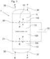
- the present invention relates to a reactor 1 for carrying out an endothermic reaction, as described in the Figures 1 to 3 shown in different embodiments and applications.
- the reactor 1 is designed to carry out an endothermic reaction in which a product gas P is obtained from a feed gas E.
- Fig.1 shows a variant in which ethane as feed gas E is converted to ethene (C 2 H 4 ) and hydrogen (H 2 ) as product gas P.
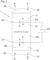
- the reactor can alternatively be operated according to Figure 2 can also be used for steam reforming, where methane (CH 4 ) as feed gas is converted together with water vapor (H 2 O) to carbon monoxide and hydrogen as product gas P or synthesis gas. Other reactions are also conceivable.
- the reactor bed 120 in the reaction zone 12 and the reactor beds 110, 130 in the heat integration zones are solid particles F driven by gravity, wherein the feed gas E forms a countercurrent gas flow, so that preferably an almost complete heat integration can be achieved.
- the heating and cooling of gases takes place on a time scale of 0.1 s to 1 s, which is advantageous for the reaction if, for example, rapid cooling to a lower temperature of the product gas is required.
- the heat capacity flows of the gas and solid particle flows E, P, F are adapted to one another. This leads to so-called heat integration zones 11, 13 in the reactor interior 10 or moving bed 110, 130, in which the feed gas E is preheated by hot solid particles F from the reaction zone 12 (lower second heat integration zone 13) and hot product gas P heats cold solid particles F that are introduced at the top of the reactor 1.
- reaction zone 12 is arranged in the vertical direction between the two electrodes 20, 21 when the reactor 1 is arranged as intended, wherein the first heat integration zone 11 is arranged above the first electrode 20, and wherein the second heat integration zone 21 is arranged below the second electrode.
- the respective reactor 1 has a solid particle inlet 30, via which solid particles F can be introduced into the first heat integration zone 11, so that the solid particles F can be guided past the first electrode 20 into the reaction zone 12 and further past the second electrode 21 into the second heat integration zone 13.
- the reactor 1 For removing the solid particles F (and in particular for recirculating the solid particles F to the solid particle inlet 30), the reactor 1 further comprises a solid particle outlet 31 through which the solid particles F can be removed from the second heat integration zone 13.
- the respective reactor 1 for introducing the feed gas E into the reactor interior 10 has a feed gas inlet 32, via which the feed gas E can be introduced into the second heat integration zone 13 and from there can be guided past the second electrode 21 into the reaction zone 12.
- the respective reactor 1 has a product gas outlet 33, via which product gas P generated in the reaction zone 12 can be withdrawn from the first heat integration zone 11.
- Figure 1 In the production of ethylene, at least 90% of the heat used is recovered, whereby solid particles F made of carbon are used for the calculation. Instead of carbon, however, ceramic materials are preferably used. In particular, solid particles F made of, for example, Al 2 O 3 can be used in the present invention as a component of the reactor bed.
- the feed gas (ethane) E can be introduced into the reactor 1 at a temperature of e.g. 150°C and a pressure of e.g. 2 bar at a mass flow of e.g. 1000 kg/h.
- the feed gas E can be diluted with steam which has a temperature of e.g. 155°C at a pressure of e.g. 2 bar and a mass flow of e.g. 300 kg/h.
- the conversion of ethane to ethylene can be carried out in the reaction zone at a temperature of e.g. 850°C, whereby the ethylene product can be withdrawn from the reactor 1 at a temperature of e.g. 150°C, a pressure of e.g.
- the solid particles F can also be introduced into the reactor 1 at a temperature of e.g. 174°C and a pressure of e.g. 2 bar and a mass flow of 2.9 t/h and withdrawn from the reactor 1 at a temperature of 280°C.
- the heating output is 1550 kWh/t ethylene product.
- the electrical consumption is 1722 kWh/t ethylene product.
- the reactor 1 according to the invention or the process according to the invention can be Figure 2 can also be used for steam methane reforming.
- a catalyst can also be used as a solid medium or solid particles F in the moving bed 110, 120, 130.
- the catalyst requires increased abrasion resistance compared to a tubular fixed bed reactor, but can advantageously be subjected to external catalyst regeneration.
- the decision as to whether inert particles or particles that influence the reaction should be used can be made in particular on the basis of the reaction temperature.
- a catalyst material can be used in the lower temperature range (at approx. 950°C), while in the upper temperature range (at approx. 1250°C) the reactions proceed sufficiently quickly and an inert material can be used.
- the reactor is designed to guide the solid particles through the reaction zone 12 or the heat integration zones 11, 13 at a defined speed, wherein preferably this speed of the solid particles F (eg in the embodiments according to Figures 1 and 2 ) is in the range of 0.1 m/h to 2 m/h, which is a slow and very material-friendly speed at which the risk of friction-related damage to the reactor is correspondingly lower.
- this speed of the solid particles F eg in the embodiments according to Figures 1 and 2
- this speed of the solid particles F is in the range of 0.1 m/h to 2 m/h, which is a slow and very material-friendly speed at which the risk of friction-related damage to the reactor is correspondingly lower.
- Direct electrical heating of a carbon moving bed 120 by means of the electrodes 20, 21 at ⁇ 800°C to -1250°C is possible with electrical resistances in the range of -1.0 ohm to 10 ohm.
- electrical resistances in the range of -1.0 ohm to 10 ohm.
- solid particles F in the form of carbon particles with a specific bed resistance of ⁇ 0.005-0.04[ohm*m] at temperatures in the range above 800°C can be used.
- the solid particles F of the moving bed 110, 120, 130 should be sufficiently chemically stable under the reaction conditions, so that ceramic materials are preferred over carbon if the reactant gas contains steam or large amounts of CO 2.
- the respective solid medium F can be selected depending on the process requirements. In principle, low-resistance materials, e.g. ceramic materials, are advantageous, whereby the electrical conductivity should preferably be higher than that of the refractory lining material of the reactor 1, so that heating primarily takes place in the reactor bed 120 and not in the surrounding refractory material of the reactor.
- the contact resistance between the individual solid particles F is particularly important for the overall resistance. The surface morphology can therefore be adjusted in such a way that it causes an increased electrical resistance.
- the solid particles are, for example, non-spherical particles.
- the length of the reaction zone 12 in the vertical direction or in the flow direction of the solid particles F and the feed gas stream E defines the residence time of the gas in the heated zone 12.
- the greater the length the more favorable the conditions are for electrical heating, since a correspondingly high total electrical resistance results (series contact resistances of the particles F).
- Residence times of less than 1 s in the reaction zone 12 are possible, which is advantageous for ethylene production by ethane dehydrogenation.
- the particle size of the solid particles F can be selected depending on the reactor requirements. For example, for ethane dehydrogenation, rapid heating is advantageous, with particle sizes in the range of maximum 5 mm for efficient direct heat transfer between the gas and solid phases. Short heating times of 0.1 s to 1 s are thus easily possible.
- a monomodal particle size distribution of the solid particles F also proves to be advantageous, since this leads to a homogeneous heating and approximately to a plug flow, without demixing due to partial fluidization.
- the selection of the electrode material of the electrodes 20, 21 is based in particular on the following criteria, according to which a stable material under the reaction conditions (temperature, gas conditions, solid fluidized bed materials) is preferred, which has a comparatively high electrical conductivity compared to the bed medium in order to ensure heating in the bed and not in the electrode, whereby the material should also allow manufacturability in the form required for the entire electrode.
- the respective electrode 20 is designed, for example, as a single or as several struts, but can also have a more complex lattice shape.
- Stainless steels or Ni-based alloys duee to high temperatures) can be considered as electrode material for the above-mentioned processes.
- the material Centralloy ® G 4852 Micro R is stable under reformer conditions, has an acceptable strength and can be used as electrode material. If there is no steam (no steam dilution) or CO 2 in the feed or product gas E, P, graphite can in principle also be used as electrode material. Alternatively, graphite can be coated with a chemically stable protective layer, which must, however, be electrically conductive.
- the reaction zone 12 of the reactor 1 is delimited by a circumferential wall section 12a of the reactor 1, which has an inner side 12b facing the reaction zone 12, which is conical in shape, so that the reaction zone 12 tapers upwards in the vertical direction z.
- the diameter D1 of the reaction zone 12 is reduced to the diameter D2 of the reaction zone 12.
- the inner side 12b forms in particular a lateral surface of a truncated cone.
- the reaction zone 12 in this area forms in particular a truncated cone.
- Such a conically widening geometry of the reaction zone 12 advantageously leads to a lateral movement of solid particles F of the moving bed 120 in the reaction zone 12.
- a bridge can be formed which is broken up again by the lateral movement of the particles F and thus does not lead to blockage.
- the inner side 12b preferably forms an angle W with a horizontal plane or a horizontal cross section of the reaction zone 12, which may be relatively close to 90°.
- the angle W is in a range of 85° to 89.5°, preferably in the range 87° to 89°.
- the reactor according to the invention can be used for any other endothermic reaction, whereby preferably no increased solids production should occur in the reaction zone 12.
- a blockage of the moving bed 120 and the corresponding change in the resistance of the bed prove to be disadvantageous.
- an alternating voltage instead of a direct voltage 22 can be applied to the resistance heater.
- the present invention advantageously enables a reduced direct emission of CO 2 from the process due to the specific heating of the particles F. Furthermore, due to the heat integration between products and reactants in the reactor itself, no or only reduced external equipment for heat recovery is necessary.
- the invention allows comparatively short heating and cooling times, which leads to a good reaction control. This is particularly advantageous since rapid cooling of the gas emerging from the reaction zone is necessary during steam cracking in order to increase the yield of the target product.
Landscapes
- Chemical & Material Sciences (AREA)
- Organic Chemistry (AREA)
- Chemical Kinetics & Catalysis (AREA)
- Health & Medical Sciences (AREA)
- General Health & Medical Sciences (AREA)
- Engineering & Computer Science (AREA)
- Combustion & Propulsion (AREA)
- Inorganic Chemistry (AREA)
- Devices And Processes Conducted In The Presence Of Fluids And Solid Particles (AREA)
- Organic Low-Molecular-Weight Compounds And Preparation Thereof (AREA)
Description
- Die Erfindung betrifft einen Reaktor für endotherme Hochtemperaturreaktionen, z.B. zur Durchführung einer Dampfreformation eines kohlenwasserstoffhaltigen Einsatzgasstromes (z.B. aufweisend Methan) oder z.B. zum Cracken bzw. thermischen Spalten von Ethan oder z.B. zur Pyrolyse von Erdgas (z.B. aufweisend Methan).
- In Öfen bzw. Reaktoren für das Ethancracking oder die Dampfreformation von Methan werden fossile Brennstoffe verbrannt, um thermische Energie zu erzeugen, um z.B. den jeweiligen Einsatzstoffstrom bzw. Prozessgase mittels indirekter Wärmeübertragung zu erhitzen. Dabei entstehen durch die Verbrennung fossiler Brennstoffe unweigerlich CO2-Emissionen. Die Energieeffizienz wird hierbei in der Regel erhöht, indem Verbrennungsluft vorgeheizt wird, der Einsatz vorgeheizt wird und/oder indem Wärme eines heißen Prozessgases auf Kesselspeisewasser zur Erzeugung von Prozessdampf übertragen wird.
- Als Alternative zum etablierten Stand der Technik offenbart die
US2,982,622 z.B. ein Verfahren zur Herstellung von Wasserstoff und hochwertigem Koks, bei dem inerte Feststoffteilchen als Schüttgut in Gravitationsrichtung durch eine längliche Reaktionszone geleitet werden, eine elektrische Spannung von 0,1 bis 1000 Volt pro Zoll über mindestens einen Teil der Feststoffmasse in der Reaktionszone angelegt wird, wobei die Spannung ausreicht, um die Temperatur der Feststoffe auf 1800°F bis 3000°F (980°C bis 1650°C) zu erhöhen. Im Gegenstrom wird ein Gasstrom aus Kohlenwasserstoffen, vorzugsweise Erdgas geführt, der über die endotherme Pyrolysereaktion Wasserstoff erzeugt und Kohlenstoff auf den vorgelegten Partikeln ablagert
CH4 <-> C(s) + 2 H2.
- Durch die Gegenstrombedingung von Feststoff und Gas kann eine Wärmeintegration erreicht werden, wodurch eine hohe Effizienz des Verfahrens ermöglicht wird. Durch die ohmsche, direktelektrische Beheizung kann bei Verwendung von Strom, der mit Hilfe von erneuerbaren Energien erzeugt wurde, die CO2-Bilanz des Verfahrens der Wasserstoffproduktion durch einen Verzicht auf die fossile Beheizung verbessert werden.
- Diesbezüglich wurde jedoch anhand von Untersuchungen festgestellt, dass der aus der Gasphase abgeschiedene Kohlenstoff zu einer Reduktion der Rieselfähigkeit der inerten Feststoffteilchen führt und nach längerem Betrieb zu einer Verblockung des Schüttgutes führt, was die Wirtschaftlichkeit eines solchen Verfahrens deutlich einschränkt.
- Hiervon ausgehend liegt der vorliegenden Erfindung die Aufgabe zugrunde, einen verbesserten Reaktor bereitzustellen, der auf eine fossile Beheizung der endothermen Reaktion verzichtet und gleichzeitig einen effizienten Betrieb des Reaktors gestattet.
- Diese Aufgabe wird durch einen Reaktor mit den Merkmalen des Anspruchs 1 gelöst. Vorteilhafte Ausgestaltungen der Erfindung sind in den zugehörigen Unteransprüchen angegeben und werden nachfolgend beschrieben.
- Reaktor zur Durchführung einer endothermen Reaktion, insbesondere Hochtemperaturreaktion, bei der aus einem Einsatzgas ein Produktgas gewonnen wird, wobei der Reaktor einen Reaktorinnenraum umgibt, der vorzugsweise in drei Zonen eingeteilt ist, nämlich eine erste Wärmeintegrationszone, eine Reaktionszone und eine zweite Wärmeintegrationszone. Der Reaktor ist dazu konfiguriert, in Gravitationsrichtung ein Bewegtbett zu führen, wobei das Bewegtbett aus einer Vielzahl an Feststoffpartikeln, die mit einer Geschwindigkeit von 0,1 m/h bis 2 m/h geführt werden, besteht, die am oberen Ende des Reaktor aufgegeben und am unteren Ende des Reaktors abgezogen werden, wobei der Reaktor weiterhin dazu konfiguriert ist, ein Einsatzgas durch die Reaktionszone zu führen, wobei der Reaktor zum Heizen des Einsatzgases dazu ausgebildet ist, die Feststoffpartikel in der Reaktionszone zu heizen, durch Erzeugung eines elektrischen Stromes in den Feststoffpartikeln, d.h., durch Erzeugung deutscher Wärme in den Feststoffpartikeln, so dass der Reaktor zum Heizen der Feststoffpartikel des Reaktorbetts eine erste und eine zweite Elektrode aufweist, wobei die erste Elektrode oberhalb der zweiten Elektrode im Reaktorinnenraum angeordnet ist, so dass das Einsatzgas in der Reaktionszone durch Übertragung von Wärme der Feststoffpartikel auf das Einsatzgas auf eine Reaktionstemperatur heizbar ist, um als Edukt an der endothermen Reaktion zur Erzeugung des Produktgases teilzunehmen, und wobei der Reaktorinnenraum weiterhin eine erste Wärmeintegrationszone aufweist, in der Wärme des in der Reaktionszone erzeugten Produktgases auf in die Reaktionszone zu führende Feststoffpartikel des Reaktorbetts übertragbar ist, und wobei weiterhin der Innenraum eine zweite Wärmeintegrationszone aufweist, in der Wärme von aus der Reaktionszone kommenden Feststoffpartikeln des Reaktorbetts zum Vorheizen des Einsatzgases auf das Einsatzgas übertragbar ist, dass die Reaktionszone zwischen den beiden Elektroden angeordnet ist, wobei die erste Wärmeintegrationszone oberhalb der ersten Elektrode angeordnet ist, und wobei die zweite Wärmeintegrationszone unterhalb der zweiten Elektrode angeordnet ist..
- Gemäß einer Ausführungsform des Reaktors ist vorgesehen, dass der Reaktor zum Heizen der Feststoffpartikel des Bewegtbetts eine erste und eine zweite Elektrode aufweist, wobei die erste Elektrode oberhalb der zweiten Elektrode im Innenraum angeordnet ist, und wobei insbesondere die beiden Elektroden für die Feststoffpartikel, das Einsatzgas und das Produktgas jeweils durchlässig sind. D.h., dass die beiden Elektroden so angeordnet bzw. ausgestaltet sind, dass die Fließfähigkeit der Feststoffpartikel nicht beeinträchtigt wird und die Feststoffpartikel, das Einsatzgas sowie das Produktgas die Elektroden im Reaktorinnenraum passieren können.
- Gemäß einer Ausführungsform des Reaktors kann die erste und/oder die zweite Elektrode eine oder mehrere Streben aufweisen, die sich durch den Reaktorinnenraum erstrecken.
- Weiterhin ist gemäß einer Ausführungsform vorgesehen, dass die erste Elektrode ein Gitter aufweist oder durch ein Gitter gebildet ist. Weiterhin kann auch die zweite Elektrode ein Gitter aufweisen oder durch ein Gitter gebildet sein.
- Weiterhin ist gemäß einer Ausführungsform der Erfindung vorgesehen, dass die erste und/oder die zweite Elektrode (bzw. die jeweilige Strebe oder das Gitter der ersten und/oder der zweiten Elektrode) eines der folgenden Materialien aufweist oder aus einem der folgenden Materialien besteht: ein hochtemperaturbeständiger Stahl, eine Stahllegierung aufweisend Ni (z.B. Centralloy G 4852 Micro R), eine Nickelbasislegierung, Siliziumkarbid, Molybdändisilicid, Graphit.
- Grundsätzlich werden Materialien bevorzugt, die sich durch eine Hochtemperaturbeständigkeit (chemische und mechanische Stabilität bei hohen Temperaturen) und eine möglichst hohe elektrische Leitfähigkeit auszeichnen. Im Falle von Graphit kann die chemische Stabilität bei Anwesenheit von Dampf und hohen Temperaturen beispielsweise durch eine Schutzbeschichtung verbessert werden.
- Ebenfalls ist gemäß einer Ausführungsform vorgesehen, dass die Elektroden, eine elektrische Zufuhr zu den Elektroden, sowie das Bewegtbett zum Druckmantel des Reaktors hin elektrisch isoliert sind. Dies wird z. B. durch eine elektrisch schwachleitfähige Hochtemperaturausmauerung, beispielsweise aus Al2O3 oder ZrO2 erreicht.
- Weiterhin ist gemäß einer Ausführungsform der Erfindung vorgesehen, dass der Reaktor dazu konfiguriert ist, zum Heizen der Feststoffpartikel eine Gleichspannung zwischen den beiden Elektroden bereitzustellen bzw. anzulegen.
- Weiterhin ist gemäß einer Ausführungsform des Reaktors vorgesehen, dass der Reaktor einen Feststoffpartikeleinlass aufweist, über den Feststoffpartikel in die erste Wärmeintegrationszone einleitbar sind, so dass die Feststoffpartikel an der ersten Elektrode vorbei in die Reaktionszone führbar sind und weiterhin an der zweiten Elektrode vorbei in die zweite Wärmeintegrationszone führbar sind.
- Weiterhin ist gemäß einer Ausführungsform des Reaktors vorgesehen, dass der Reaktor einen Feststoffpartikelauslass aufweist, über den die Feststoffpartikel aus der zweiten Wärmeintegrationszone abziehbar sind, beispielweise eine Zellradschleuse. Diese ist das maßgebliche Steuerungselement für die Wandergeschwindigkeit bzw. den Massenstrom des Bewegtbetts.
- Weiterhin ist gemäß einer Ausführungsform des Reaktors vorgesehen, dass der Reaktor einen Einsatzgaseinlass aufweist, über den das Einsatzgas in die zweite Wärmeintegrationszone einleitbar und von dort an der zweiten Elektrode vorbei in die Reaktionszone einleitbar ist.
- Weiterhin ist gemäß einer Ausführungsform des Reaktors vorgesehen, dass der Reaktor einen Produktgasauslass aufweist, über den in der Reaktionszone erzeugtes Produktgas aus der ersten Wärmeintegrationszone abziehbar ist.
- Weiterhin ist gemäß einer Ausführungsform des Reaktors vorgesehen, dass der Reaktor dazu konfiguriert ist, die Feststoffpartikel in der ersten und/oder der zweiten Wärmeintegrationszone schwerkraftangetrieben in Form eines Bewegtbetts zu führen.
- Gemäß einer weiteren Ausführungsform des Reaktors ist vorgesehen, dass der Reaktor dazu konfiguriert ist, die Feststoffpartikel in der Reaktionszone schwerkraftgetrieben in Form eines Bewegtbetts zu führen.
- Weiterhin ist gemäß einer Ausführungsform des Reaktors vorgesehen, dass die Reaktionszone des Reaktors durch einen umlaufende Wandungsabschnitt des Reaktors begrenzt ist, der eine der Reaktionszone zugewandte Innenseite aufweist, die konusförmig ausgebildet ist, so dass sich die Reaktionszone in vertikaler Richtung nach oben hin verjüngt. Gemäß einer Ausführungsform kann dabei die Innenseite einen Winkel mit einem horizontalen Querschnitt der Reaktionszone bilden, wobei der Winkel vorzugsweise in einem Bereich von 85° bis 89,5°, bevorzugt 87° bis 89°, liegt.
- Ein weiterer Aspekt der vorliegenden Erfindung betrifft ein Verfahren zur Durchführung einer endothermen Reaktion zur Gewinnung eines Produktgases aus einem Einsatzgas unter Verwendung eines erfindungsgemäßen Reaktors, wobei
- eine Vielzahl an Feststoffpartikeln in die erste Wärmeintegrationszone und von dort in die Reaktionszone geführt werden,
- die mit einer Geschwindigkeit von 0,1 m/h bis 2 m/h geführt werden,
- die Feststoffpartikel in der Reaktionszone erhitzt werden,
- die Feststoffpartikel aus der Reaktionszone in die zweite Wärmeintegrationszone geführt werden und aus der zweiten Wärmeintegrationszone abgezogen werden,
- das Einsatzgas in die zweite Wärmeintegrationszone und von dort in die Reaktionszone eingeleitet wird, wobei das Einsatzgas in der zweiten Wärmeintegrationszone gegen aus der Reaktionszone kommende Feststoffpartikel erhitzt wird, wobei die Feststoffpartikel abgekühlt werden, und wobei das Einsatzgas in der Reaktionszone mit den erhitzten Feststoffpartikeln kontaktiert wird, wobei Wärme der erhitzten Feststoffpartikel zum Erhitzen des Einsatzgases in der Reaktionszone auf das Einsatzgas übertragen wird, wobei das Einsatzgas in der Reaktionszone als ein Edukt an der Reaktion unter Erzeugung des Produktgases teilnimmt,
- das erzeugte Produktgas aus der Reaktionszone in die erste Wärmeintegrationszone geführt wird, wobei die Feststoffpartikel in der ersten Wärmeintegrationszone gegen das aus der Reaktionszone kommende Produktgas vorgeheizt werden, wobei das Produktgas abgekühlt wird, und wobei
- das Produktgas aus der ersten Wärmeintegrationszone abgezogen wird.
- Bevorzugt werden die Feststoffpartikel bei dem Verfahren gemäß einer Ausführungsform im Kreislauf geführt. D.h. insbesondere, dass die aus der zweiten Wärmeintegrationszone abgezogenen Feststoffpartikel (ggf. nach einer Zwischenbehandlung der Feststoffpartikel) wieder in die erste Wärmeintegrationszone eingeleitet werden.
- Gemäß einer weiteren Ausführungsform des Verfahrens handelt es sich bei dem Einsatzgas um Ethan (C2H6) zusammen mit Wasserdampf (H2O), das in der Reaktionszone bei vorzugsweise bei Temperaturen von etwa 850°C bis 1250°C und Drücken von 1-5 bar(a) zu Ethen (C2H4) und Wasserstoff (H2) als Produktgas umgesetzt wird, wobei als Feststoffpartikel Keramikkugeln, beispielsweise aus Korund (Al2O3), verwendet werden.
- Gemäß einer weiteren Ausführungsform des Verfahrens handelt es sich bei der endothermen Reaktion um eine Dampfreformierung:
CH4+H2O -> CO + 3H2,
wobei als Einsatzgas Methan (CH4) zusammen mit Wasserdampf (H2O) in der Reaktionszone (vorzugsweise bei Temperaturen von etwa 950°C bis 1250°C und Drücken von 10 bar(a) bis 100 bar(a) (vorzugsweise bei Drücken von 15bar(a) bis 50 bar(a)) zu Kohlenmonoxid und Wasserstoff als Produktgas umgesetzt wird, wobei wiederum als Feststoffpartikel bevorzugt Keramikkugeln, beispielsweise aus Korund (Al2O3), verwendet werden oder alternativ ein abriebsbeständiger Katalysator auf Ni-Basis. - Weiterhin kann es sich bei der Reaktion gemäß einer Ausführungsform auch um eine reverse Wassergas-Shift-Reaktion handeln:
CO2+H2 -> CO + H2O,
bei der CO2 und H2 als Einsatz zu CO und H2O umgesetzt werden, wobei wiederum als Feststoffpartikel Keramikkugeln, beispielsweise aus Korund (Al2O3), verwendet werden oder alternativ ein abriebsbeständiger Katalysator auf Ni-Basis. - Grundsätzlich kann es sich bei der Reaktion auch um eine Dampfspaltung handeln, bei der Naphtha als Einsatz verwendet wird.
- Weiterhin kann es sich bei der Reaktion gemäß einer Ausführungsform um eine Propan-Dehydrierung zu Propen handeln (C3H8 -> C3H6 + H2), wobei Propan als Einsatz verwendet wird und die Feststoffpartikel des Reaktorbetts einen für die Reaktion geeigneten Katalysator bilden. Der Katalysator erfordert im Vergleich zu einem Rohrfestbettreaktor eine erhöhte Abriebfestigkeit, kann aber mit Vorteil einer externen Katalysatorregeneration unterzogen werden, falls durch die Reaktion eine Verkokung auftritt.
- Weiterhin kann es sich bei der Reaktion gemäß einer Ausführungsform auch um eine Butan-Dehydrierung zu Buten handeln (C4H10 -> C4H8 + H2), wobei Butan als Einsatz verwendet wird und wiederum die Feststoffpartikel des Reaktorbetts einen für die Reaktion geeigneten Katalysator bilden.
- Weiterhin kann es sich bei der Reaktion gemäß einer Ausführungsform auch um eine Buten-Dehydrierung zu Butadien handeln (C4H8 -> C4H6 + H2), wobei Buten als Einsatz verwendet wird und wiederum die Feststoffpartikel des Reaktorbetts einen für die Reaktion geeigneten Katalysator bilden.
- Weiterhin kann es sich bei der Reaktion gemäß einer Ausführungsform auch um eine Ethylbenzen-Dehydrierung zu Styrol handeln (C8H10 -> C8H8 + H2), wobei Ethylbenzen als Einsatz verwendet wird und wiederum die Feststoffpartikel des Reaktorbetts einen für die Reaktion geeigneten Katalysator bilden.
- Weitere Merkmale und Vorteile der vorliegenden Erfindung sollen bei der Beschreibung von Ausführungsbeispielen anhand der Figuren erläutert werden. Es zeigen:
- Fig. 1
- eine schematische Darstellung einer Ausführungsform eines erfindungsgemäßen Reaktors bzw. eines erfindungsgemäßen Verfahrens;
- Fig. 2
- eine schematische Darstellung einer weiteren Ausführungsform eines erfindungsgemäßen Verfahrens; und
- Fig. 3
- eine schematische Darstellung einer Ausführungsform einer Reaktionszone eines erfindungsgemäßen Reaktors bzw. eines erfindungsgemäßen Verfahrens.
- Die vorliegende Erfindung betrifft einen Reaktor 1 zur Durchführung einer endothermen Reaktion, wie er in den
Figuren 1 bis 3 in unterschiedlichen Ausführungsformen bzw. Anwendungen gezeigt ist. - Der Reaktor 1 ist zur Durchführung einer endothermen Reaktion ausgebildet, bei der aus einem Einsatzgas E ein Produktgas P gewonnen wird.
Fig. 1 zeigt diesbezüglich eine Variante, bei der Ethan als Einsatzgas E zu Ethen (C2H4) und Wasserstoff (H2) als Produktgas P umgesetzt wird. Der Reaktor kann alternativ z.B. gemäßFigur 2 auch zur Dampfreformierung verwendet werden, wobei als Einsatzgas Methan (CH4) zusammen mit Wasserdampf (H2O) zu Kohlenmonoxid und Wasserstoff als Produktgas P bzw. Synthesegas umgesetzt wird. Andere Reaktionen sind ebenfalls denkbar. - Der Reaktor 1 umgibt gemäß den
Figuren 1 bis 3 jeweils einen Reaktorinnenraum 10, wobei der Reaktor 1 dazu konfiguriert ist, in einer Reaktionszone 12 des Reaktorinnenraumes 10 ein Reaktorbett 120 aufweisend eine Vielzahl an Feststoffpartikeln F bereitzustellen, wobei der Reaktor 1 weiterhin dazu konfiguriert ist, das Einsatzgas E in die Reaktionszone 12 zu führen, wobei der Reaktor 1 zum Heizen des Einsatzgases E dazu ausgebildet ist, die Feststoffpartikel F in der Reaktionszone 12 zu heizen, so dass das Einsatzgas E in der Reaktionszone 12 durch Übertragung von Wärme der Feststoffpartikel F auf das Einsatzgas E auf eine Reaktionstemperatur heizbar ist, um als Edukt an der jeweiligen endothermen Reaktion zur Erzeugung des Produktgases P teilzunehmen, und wobei der Reaktorinnenraum 10 weiterhin eine erste Wärmeintegrationszone 11 aufweist, in der Wärme des in der Reaktionszone 12 erzeugten Produktgases P auf in die Reaktionszone 12 zu führende Feststoffpartikel F des Reaktorbetts 120 übertragbar ist, und wobei weiterhin der Reaktorinnenraum 10 eine zweite Wärmeintegrationszone 13 aufweist, in der Wärme von aus der Reaktionszone 12 kommenden Feststoffpartikeln F des Reaktorbetts 120 zum Vorheizen des Einsatzgases E auf das Einsatzgas E übertragbar ist. - Bei den in den
Figuren 1 und2 gezeigten Ausführungsformen des Reaktors 1 handelt es sich bei dem Reaktorbett 120 in der Reaktionszone 12 sowie bei den Reaktorbetten 110, 130 in den Wärmeintegrationszonen um durch Schwerkraft angetriebene Feststoffpartikel F, wobei das Einsatzgas E einen Gegenstrom-Gasstrom bildet, so dass vorzugsweise eine nahezu vollständige Wärmeintegration erzielbar ist. - Das Aufheizen und Abkühlen von Gasen erfolgt dabei gemäß einer Ausführungsform auf einer Zeitskala von 0,1 s bis 1 s, was für die Reaktionsführung von Vorteil ist, wenn z.B. ein schnelles Abkühlen auf eine niedrigere Temperatur des Produktgases erforderlich ist.
- Wie anhand der
Figuren 1 und2 ersichtlich ist, wird zum Heizen des Einsatzgases E eine direkte elektrische (oder induktive) Erwärmung der Feststoffpartikel F verwendet. Hierzu können entsprechend durchlässige Elektroden 20, 21, insbesondere in Form von Gittern 20, 21, verwendet werden, wobei eine elektrische Spannung 22 an die Elektroden 20, 21 angelegt wird und damit der Widerstand der Feststoffpartikel F (hauptsächlich Festkörper gegen Festkörper-Kontaktwiderstände anstelle von Materialwiderständen) für die Wärmeproduktion/Wärmeabgabe genutzt wird. - Um eine optimale Wärmeintegration zu erreichen, werden gemäß einer bevorzugten Ausführungsform die Wärmekapazitätsströme der Gas- und Feststoffpartikelströme E, P, F aneinander angepasst. Dies führt zu so genannten Wärmeintegrationszonen 11, 13 im Reaktorinnenraum 10 bzw. Bewegtbett, 110, 130, in denen das Einsatzgas E durch heiße Feststoffpartikel F aus der Reaktionszone 12 (untere zweite Wärmeintegrationszone 13) vorgewärmt wird und heißes Produktgas P kalte Feststoffpartikel F erwärmt, die an der Oberseite des Reaktors 1 eingebracht werden.
- Gemäß den
Figuren 1 und2 ist hierbei bevorzugt vorgesehen, dass die Reaktionszone 12 bei bestimmungsgemäß angeordnetem Reaktor 1 in vertikaler Richtung zwischen den beiden Elektroden 20, 21 angeordnet ist, wobei die erste Wärmeintegrationszone 11 oberhalb der ersten Elektrode 20 angeordnet ist, und wobei die zweite Wärmeintegrationszone 21 unterhalb der zweiten Elektrode angeordnet ist. - Zum Einleiten der das jeweilige Reaktorbett 110, 120, 130 bildenden Feststoffpartikel F ist weiterhin vorgesehen, dass der jeweilige Reaktor 1 einen Feststoffpartikeleinlass 30 aufweist, über den Feststoffpartikel F in die erste Wärmeintegrationszone 11 einleitbar sind, so dass die Feststoffpartikel F an der ersten Elektrode 20 vorbei in die Reaktionszone 12 führbar sind und weiterhin an der zweiten Elektrode 21 vorbei in die zweite Wärmeintegrationszone 13 führbar sind.
- Zum Abziehen der Feststoffpartikel F (und insbesondere zum Rezirkulieren der Feststoffpartikel F zum Feststoffpartikeleinlass 30) weist der Reaktor 1 weiterhin einen Feststoffpartikelauslass 31 auf, über den die Feststoffpartikel F aus der zweiten Wärmeintegrationszone 13 abziehbar sind.
- Weiterhin weist insbesondere der jeweilige Reaktor 1 zum Einleiten des Einsatzgases E in den Reaktorinnenraum 10 einen Einsatzgaseinlass 32, über den das Einsatzgas E in die zweite Wärmeintegrationszone 13 einleitbar und von dort an der zweiten Elektrode 21 vorbei in die Reaktionszone 12 führbar ist.
- Zum Abziehen des Produktgases P weist der jeweilige Reaktor 1 schließlich einen Produktgasauslass 33 auf, über den in der Reaktionszone 12 erzeugtes Produktgas P aus der ersten Wärmeintegrationszone 11 abziehbar ist.
- Gemäß einem Beispiel der Erfindung kann gemäß
Figur 1 bei der Erzeugung von Ethylen zumindest 90% der eingesetzten Wärme zurückgewonnen werden, wobei zur Berechnung von Feststoffpartikeln F aus Kohlenstoff ausgegangen wird. Anstelle von Kohlenstoff werden jedoch bevorzugt keramische Materialien verwendet. Insbesondere können Feststoffpartikel F aus z. B. Al2O3 bei der vorliegenden Erfindung als Bestandteil des Reaktorbetts verwendet werden. - Zum Erzielen der vorgenannten Wärmerückgewinnung kann das Einsatzgas (Ethan) E mit einer Temperatur von z.B. 150°C und einem Druck von z.B. 2 bar bei einem Massenstrom von z.B. 1000 kg/h in den Reaktor 1 eingeleitet werden. Das Einsatzgas E kann dabei mit Dampf verdünnt werden, der eine Temperatur von z.B. 155°C bei einem Druck von z.B. 2 bar und einem Massenstrom von z.B. 300 kg/h aufweist. Die Umsetzung von Ethan zu Ethylen kann in der Reaktionszone bei einer Temperatur von z.B. 850°C vorgenommen werden, wobei das Ethylenprodukt z.B. mit einer Temperatur von 150°C bei einem Druck von z.B. 2 bar und einem Massenstrom von z.B. 606 kg/h aus dem Reaktor 1 abgezogen werden kann. Die Feststoffpartikel F können des Weiteren bei einer Temperatur von z.B. 174°C und einem Druck von z.B. 2 bar und einem Massenstrom von 2.9 t/h in den Reaktor 1 eingeleitet werden und bei einer Temperatur von 280°C aus dem Reaktor 1 abgezogen werden.
- Bei gegebener Konvertierung von 65% des Einsatzes Ethan zu Ethylen (bei einer Dampfverdünnung des Einsatzes mit 30% Wasserdampf) beträgt die Heizleistung 1550 kWh/t Ethylenprodukt. Bei 90% Umwandlungswirkungsgrad elektrischer Energie beträgt der elektrische Verbrauch 1722 kWh/t Ethylenprodukt.
- Ähnlich wie bei der Ethanspaltung kann der erfindungsgemäße Reaktor 1 bzw. das erfindungsgemäße Verfahren gemäß
Figur 2 auch zur Dampfmethanreformierung realisiert werden. Anstelle von inerten Partikeln kann auch ein Katalysator als Feststoffmedium bzw. Feststoffpartikel F im Bewegtbett 110, 120, 130 eingesetzt. Der Katalysator erfordert im Vergleich zu einem Rohrfestbettreaktor eine erhöhte Abriebfestigkeit, kann aber mit Vorteil einer externen Katalysatorregeneration unterzogen werden. Die Entscheidung, ob inerte Partikel oder die Reaktion beeinflussende Partikel verwendet werden sollen, kann insbesondere auf Basis der Reaktionstemperatur getroffen werden. Am Beispiel der Dampfreformierung kann z.B. im unteren Temperaturbereich (bei ca. 950°C) ein Katalysatormaterial eingesetzt werden, während im oberen Temperaturbereich (bei ca. 1250°C) die Reaktionen hinreichend schnell ablaufen und ein inertes Material verwendet werden kann. - Gemäß einer Ausführungsform ist der Reaktor dazu ausgebildet, die Feststoffpartikel mit einer definierten Geschwindigkeit durch die Reaktionszone 12 oder die Wärmeintegrationszonen 11, 13 zu führen, wobei vorzugsweise diese Geschwindigkeit der Feststoffpartikel F (z.B. bei den Ausführungsformen gemäß
Figuren 1 und2 ) im Bereich von 0,1 m/h bis 2 m/h liegt, was eine langsame und sehr materialfreundliche Geschwindigkeit darstellt, bei der das Risiko von reibungsbedingten Schäden des Reaktors entsprechend geringer ist. - Die direkte elektrische Erwärmung mittels der Elektroden 20, 21 bei ~800°C bis - 1250°C eines Kohlenstoff-Bewegtbetts 120 ist bei elektrischen Widerständen im Bereich von -1,0 Ohm bis 10 Ohm möglich. Hierzu können z.B. Feststoffpartikel F in Form von Kohlenstoffpartikeln mit einem spezifischen Bettwiderstand von ~0,005-0,04[Ohm*m] bei Temperaturen im Bereich oberhalb von 800°C verwendet werden.
- Die Feststoffpartikel F des Bewegtbetts 110, 120, 130 sollten unter den Reaktionsbedingungen ausreichend chemisch stabil sein, so dass keramische Materialien gegenüber Kohlenstoff bevorzugt sind, falls im Eduktgas Dampf oder größere Mengen CO2 enthalten sind. Das jeweilige Feststoffmedium F kann je nach Prozessanforderung ausgewählt werden. Im Prinzip sind niederohmige Materialien, z.B. keramische Materialien, vorteilhaft, wobei die elektrische Leitfähigkeit vorzugsweise höher sein sollte als die des feuerfesten Ausmauerungsmaterials des Reaktors 1, so dass primär eine Erwärmung des Reaktorbetts 120 und nicht des umgebenden feuerfesten Materials des Reaktors stattfindet. Bei Verwendung von Materialien mit relativ hoher Leitfähigkeit ist vor allem der Übergangswiderstand zwischen den einzelnen Feststoffpartikeln F für den Gesamtwiderstand maßgeblich. Die Oberflächenmorphologie kann daher so abgestimmt werden, dass sie einen erhöhten elektrischen Widerstand bedingt. Gemäß einer Ausführungsform sind die Feststoffpartikel z.B. nicht-sphärische Partikel.
- Die Länge der Reaktionszone 12 in vertikaler Richtung bzw. in Strömungsrichtung der Feststoffpartikel F und des Einsatzgasstroms E definiert die Verweilzeit des Gases in der erwärmten Zone 12. Je größer die Länge, desto günstiger sind die Bedingungen für die elektrische Beheizung, da sich ein entsprechend hoher elektrischer Gesamtwiderstand ergibt (Serien-Kontaktwiderstände der Partikel F). Verweildauern von unter 1 s in der Reaktionszone 12 sind möglich, was für die Ethylenproduktion durch Ethan-Dehydrierung vorteilhaft ist.
- Weiterhin kann die Partikelgröße der Feststoffpartikel F je nach Reaktoranforderung gewählt werden. So ist z.B. für die Ethan-Dehydrierung eine schnelle Erhitzung von Vorteil, bei der Partikelgrößen im Bereich von maximal 5 mm für eine effiziente direkte Wärmeübertragung zwischen der Gas- und Feststoffphase. Niedrige Aufheizzeiten von 0,1 s bis 1 s sind so problemlos möglich.
- Weiterhin erweist sich gemäß einer Ausführungsform auch eine monomodale Partikelgrößenverteilung der Feststoffpartikel F als vorteilhaft, da diese zu einer homogenen Erwärmung und näherungsweise zu einer Pfropfenströmung führt, ohne Entmischung durch teilweise Fluidisierung.
- Die Auswahl des Elektrodenmaterials der Elektroden 20, 21 basiert insbesondere auf folgenden Kriterien, wonach ein stabiles Material unter den Reaktionsbedingungen (Temperatur, Gasbedingungen, feste Fließbettmaterialien) bevorzugt ist, das eine vergleichsweise hohe elektrische Leitfähigkeit im Vergleich zum Bettmedium aufweist, um eine Erwärmung im Bett und nicht in der Elektrode zu gewährleisten, wobei das Material weiterhin eine Herstellbarkeit in der für die gesamte Elektrode erforderlichen Form erlauben sollte. Im einfachsten Fall ist die jeweilige Elektrode 20 z.B. als eine einzelne oder als mehrere Streben ausgebildet, kann jedoch auch eine komplexere Gittergestalt aufweisen. Für die oben genannten Prozesse können als Elektrodenmaterial Edelstähle oder Ni-Basislegierungen (aufgrund von hohen Temperaturen) in Frage kommen. So ist z.B. das Material Centralloy® G 4852 Micro R unter Reformerbedingungen stabil, weist eine akzeptable Festigkeit auf und kann als Elektrodenmaterial verwendet werden. Wenn kein Dampf (keine Dampfverdünnung) oder CO2 im Einsatz- oder Produktgas E, P vorhanden ist, kann prinzipiell auch Graphit als Elektrodenmaterial verwendet werden. Alternativ kann Graphit mit einer chemisch stabilen Schutzschicht überzogen werden, die allerdings elektrisch leitend gestaltet sein muss.
- Weiterhin kann gemäß einer in der
Fig. 3 gezeigten Ausführungsform vorgesehen sein, dass die Reaktionszone 12 des Reaktors 1 durch einen umlaufenden Wandungsabschnitt 12a des Reaktors 1 begrenzt ist, der eine der Reaktionszone 12 zugewandte Innenseite 12b aufweist, die konusförmig ausgebildet ist, so dass sich die Reaktionszone 12 in vertikaler Richtung z nach oben hin verjüngt. Hierbei verringert sich der Durchmesser D1 der Reaktionszone 12 auf den Durchmesser D2 der Reaktionszone 12. - Die Innenseite 12b bildet dabei insbesondere eine Mantelfläche eines Kegelstumpfes. Mit anderen Worten formt die Reaktionszone 12 in diesem Bereich insbesondere einen Kegelstumpf.
- Eine derartig sich konisch erweiternde Geometrie der Reaktionszone 12 führt mit Vorteil zu einer lateralen Bewegung von Feststoffpartikeln F des Bewegtbetts 120 in der Reaktionszone 12. Im Falle von Ablagerungen von Kohlenstoff aus dem Einsatzgas auf den Feststoffpartikeln F, z.B. bei einer Pyrolysereaktion bei der reinen Methanpyrolyse (dampffrei) oder bei einer Verkokung bei der Dampfreformierung bei Verwendung kleiner Verhältnisse von Dampf zu Kohlenstoff (auch als S/C bezeichnet), z. B. S/C< 1, 8, insbesondere S/C<1, oder bei einer Coking-Reaktion beim Ethancracken, kann eine Brückenbildung erfolgen, die durch die laterale Bewegung der Partikel F wieder aufgebrochen wird und dadurch nicht zu einer Verblockung führt.
- Die Innenseite 12b bildet vorzugsweise einen Winkel W mit einer horizontalen Ebene bzw. einem horizontalen Querschnitt der Reaktionszone 12, der relativ nahe an 90° liegen kann.
- Vorzugsweise liegt der Winkel W in einem Bereich von 85° bis 89,5°, bevorzugt in dem Bereich 87° bis 89°.
- Grundsätzlich kann der erfindungsgemäße Reaktor für jede andere endotherme Reaktion verwendet werden, wobei vorzugsweise keine erhöhte Feststoffproduktion in der Reaktionszone 12 erfolgen sollte. In dieser Hinsicht erweist sich z. B: bei der Methanpyrolyse (CH4 -> C + 2H2) eine Blockade des beweglichen Bettes 120 und die entsprechende Widerstandsänderung des Bettes als nachteilig.
- Weiterhin kann zum Direktheizen der Partikel F mittels der Elektroden 20, 21 auch eine Wechselspannung anstelle einer Gleichspannung 22 an die Widerstandsheizung angelegt werden.
- Die vorliegende Erfindung ermöglicht mit Vorteil aufgrund der spezifischen Heizung der Partikel F eine reduzierte direkte Emission von CO2 aus dem Prozess. Weiterhin ist durch die Wärmeintegration zwischen Produkten und Edukten im Reaktor selber keine oder lediglich eine reduzierte externe Ausrüstung zur Wärmerückgewinnung notwendig.
- Die Erfindung erlaubt vergleichsweise kurze Aufheiz- und Abkühlzeiten, was zu einer guten Reaktionskontrolle führt. Dies ist insbesondere vorteilhaft, da ein schnelles Abkühlen des aus der Reaktionszone austretenden Gases beim Steamcracken nötig ist, um die Ausbeute an Zielprodukt zu steigern.
- Die Dampfproduktion kann mit Vorteil reduziert werden. Weiterhin sind bei der Ethanspaltung keine Entkokungszyklen notwendig, da auf Partikeln aufgetragener Koks aus dem Prozess entfernt werden kann. Somit kann das Entkoken mit Vorteil außerhalb des Reaktors, beispielweise durch Abbrennen an vorgewärmter Luft, erfolgen.
-
1 Reaktor 10 Reaktorinnenraum 11 Erste Wärmeintegrationszone 12 Reaktionszone 12a Wandungsabschnitt 12b Innenseite 13 Zweite Wärmeintegrationszone 20 Erste Elektrode 21 Zweite Elektrode 22 Elektrische Spannung bzw. Spannungsquelle 30 Feststoffparti keleinlass 31 Feststoffpartikelauslass 32 Einsatzgaseinlass 33 Einsatzgasauslass 110, 130 Bewegtbett 120 Bewegtbett 330 Strömungsverbindung F Feststoffpartikel (Reaktorbett) E Einsatzgas P Produktgas W Winkel
Claims (11)
- Reaktor (1) zur Durchführung einer endothermen Reaktion, insbesondere Hochtemperaturreaktion, bei der aus einem Einsatzgas (E) ein Produktgas (P) gewonnen wird, wobei der Reaktor (1) einen Reaktorinnenraum (10) umgibt, wobei der Reaktor (1) dazu konfiguriert ist, in einer Reaktionszone (12) des Reaktorinnenraumes (10) ein schwerkraftgetriebenes Bewegtbett (120) aufweisend eine Vielzahl an Feststoffpartikeln (F), die mit einer Geschwindigkeit von 0,1 m/h bis 2 m/h geführt werden, bereitzustellen, wobei der Reaktor (1) weiterhin dazu konfiguriert ist, das Einsatzgas (E) in die Reaktionszone (12) zu führen, wobei der Reaktor (1) zum Heizen des Einsatzgases (E) dazu ausgebildet ist, die Feststoffpartikel (F) in der Reaktionszone (12) durch Erzeugung eines elektrischen Stromes in den Feststoffpartikeln zu heizen, so dass der Reaktor (1) zum Heizen der Feststoffpartikel (F) des Reaktorbetts (120) eine erste und eine zweite Elektrode (20, 21) aufweist, wobei die erste Elektrode (20) oberhalb der zweiten Elektrode (21) im Reaktorinnenraum (10) angeordnet ist, so dass das Einsatzgas (E) in der Reaktionszone (12) durch Übertragung von Wärme der Feststoffpartikel (F) auf das Einsatzgas (E) auf eine Reaktionstemperatur heizbar ist, um als Edukt an der endothermen Reaktion zur Erzeugung des Produktgases (P) teilzunehmen, und wobei der Reaktorinnenraum (10) weiterhin eine erste Wärmeintegrationszone (11) aufweist, in der Wärme des in der Reaktionszone (12) erzeugten Produktgases (P) auf in die Reaktionszone (12) zu führende Feststoffpartikel (F) des Reaktorbetts (120) übertragbar ist, und wobei weiterhin der Reaktorinnenraum (10) eine zweite Wärmeintegrationszone (13) aufweist, in der Wärme von aus der Reaktionszone (12) kommenden Feststoffpartikeln (F) des Reaktorbetts (120) zum Vorheizen des Einsatzgases (E) auf das Einsatzgas (E) übertragbar ist, so dass die Reaktionszone (12) zwischen den beiden Elektroden (20, 21) angeordnet ist, wobei die erste Wärmeintegrationszone (11) oberhalb der ersten Elektrode (20) angeordnet ist, und wobei die zweite Wärmeintegrationszone (13) unterhalb der zweiten Elektrode angeordnet ist.
- Reaktor nach Anspruch 1, dadurch gekennzeichnet, dass die beiden Elektroden (20, 21) für die Feststoffpartikel (F), das Einsatzgas (E) und das Produktgas (P) jeweils durchlässig sind.
- Reaktor nach Anspruch 2, dadurch gekennzeichnet, dass der Reaktor (1) dazu konfiguriert ist, zum Heizen der Feststoffpartikel (F) eine Gleichspannung (22) oder eine Wechselspannung (22) zwischen den beiden Elektroden (20, 21) bereitzustellen.
- Reaktor nach einem der vorhergehenden Ansprüche, dadurch gekennzeichnet, dass der Reaktor (1) einen Feststoffpartikeleinass (30) aufweist, über den Feststoffpartikel (F) in die erste Wärmeintegrationszone (11) einleitbar sind, so dass die Feststoffpartikel (F) an der ersten Elektrode (20) vorbei in die Reaktionszone (12) führbar sind und weiterhin an der zweiten Elektrode (21) vorbei in die zweite Wärmeintegrationszone (13) führbar sind.
- Reaktor nach einem der vorhergehenden Ansprüche, dadurch gekennzeichnet, dass der Reaktor (1) einen Feststoffpartikelauslass (31) aufweist, über den die Feststoffpartikel (F) aus der zweiten Wärmeintegrationszone (13) abziehbar sind.
- Reaktor nach einem der vorhergehenden Ansprüche, dadurch gekennzeichnet, dass der Reaktor (1) einen Einsatzgaseinlass (32) aufweist, über den das Einsatzgas (E) in die zweite Wärmeintegrationszone (13) einleitbar und von dort an der zweiten Elektrode (21) vorbei in die Reaktionszone (12) führbar ist.
- Reaktor nach einem der vorhergehenden Ansprüche, dadurch gekennzeichnet, dass der Reaktor (1) einen Produktgasauslass (33) aufweist, über den in der Reaktionszone (12) erzeugtes Produktgas (P) aus der ersten Wärmeintegrationszone (11) abziehbar ist.
- Reaktor nach einem der vorhergehenden Ansprüche, dadurch gekennzeichnet, dass der Reaktor (1) dazu konfiguriert ist, die Feststoffpartikel (F) in der ersten und/oder der zweiten Wärmeintegrationszone (11, 13) schwerkraftangetrieben in Form eines Bewegtbetts (110, 130) zu führen.
- Reaktor nach einem der vorhergehenden Ansprüche, dadurch gekennzeichnet, dass die Reaktionszone (12) des Reaktors (1) durch einen umlaufenden Wandungsabschnitt (12a) des Reaktors (1) begrenzt ist, der eine der Reaktionszone (12) zugewandte Innenseite (12b) aufweist, die konusförmig ausgebildet ist, so dass sich die Reaktionszone (12) in vertikaler Richtung nach oben hin verjüngt.
- Reaktor nach Anspruch 9, dadurch gekennzeichnet, dass die Innenseite einen Winkel (W) mit einem horizontalen Querschnitt der Reaktionszone (12) bildet, wobei der Winkel (W) vorzugsweise in einem Bereich von 85° bis 89,5°, bevorzugt 87° bis 89°, liegt.
- Verfahren zur Durchführung einer endothermen Reaktion zur Gewinnung eines Produktgases (P) aus einem Einsatzgas (E) unter Verwendung eines Reaktors nach einem der vorhergehenden Ansprüche, wobei- eine Vielzahl an Feststoffpartikeln (F) in die erste Wärmeintegrationszone (11) und von dort in die Reaktionszone (12) geführt wird,- die Feststoffpartikel (F) mit einer Geschwindigkeit von 0,1 m/h bis 2 m/h geführt werden,- die Feststoffpartikel (F) in der Reaktionszone (12) erhitzt werden,- die Feststoffpartikel (F) aus der Reaktionszone (12) in die zweite Wärmeintegrationszone (13) geführt werden und aus der zweiten Wärmeintegrationszone (13) abgezogen werden,- das Einsatzgas (E) in die zweite Wärmeintegrationszone (13) und von dort in die Reaktionszone (12) eingeleitet wird, wobei das Einsatzgas (E) in der zweiten Wärmeintegrationszone (13) gegen aus der Reaktionszone (12) kommende Feststoffpartikel (F) erhitzt wird, wobei die Feststoffpartikel (F) abgekühlt werden, und wobei das Einsatzgas (E) in der Reaktionszone (12) mit den erhitzten Feststoffpartikeln (F) kontaktiert wird, wobei Wärme der erhitzten Feststoffpartikel (F) zum Erhitzen des Einsatzgases (E) in der Reaktionszone (12) auf das Einsatzgas (E) übertragen wird, wobei das Einsatzgas (E) in der Reaktionszone (12) als ein Edukt an der Reaktion unter Erzeugung des Produktgases (P) teilnimmt,- das erzeugte Produktgas (P) aus der Reaktionszone (12) in die erste Wärmeintegrationszone (11) geführt wird, wobei die Feststoffpartikel (F) in der ersten Wärmeintegrationszone (11) gegen das aus der Reaktionszone (12) kommende Produktgas (P) vorgeheizt werden, wobei das Produktgas (P) abgekühlt wird, und wobei- das Produktgas (P) aus der ersten Wärmeintegrationszone (11) abgezogen wird.
Priority Applications (1)
| Application Number | Priority Date | Filing Date | Title |
|---|---|---|---|
| EP24182749.2A EP4424411B1 (de) | 2019-04-05 | 2020-03-31 | Reaktor für endotherme hochtemperaturreaktionen |
Applications Claiming Priority (2)
| Application Number | Priority Date | Filing Date | Title |
|---|---|---|---|
| DE102019002523.7A DE102019002523A1 (de) | 2019-04-05 | 2019-04-05 | Reaktor für endotherme Hochtemperaturreaktionen |
| PCT/EP2020/025152 WO2020200522A1 (de) | 2019-04-05 | 2020-03-31 | Reaktor für endotherme hochtemperaturreaktionen |
Related Child Applications (2)
| Application Number | Title | Priority Date | Filing Date |
|---|---|---|---|
| EP24182749.2A Division-Into EP4424411B1 (de) | 2019-04-05 | 2020-03-31 | Reaktor für endotherme hochtemperaturreaktionen |
| EP24182749.2A Division EP4424411B1 (de) | 2019-04-05 | 2020-03-31 | Reaktor für endotherme hochtemperaturreaktionen |
Publications (2)
| Publication Number | Publication Date |
|---|---|
| EP3947261A1 EP3947261A1 (de) | 2022-02-09 |
| EP3947261B1 true EP3947261B1 (de) | 2024-07-31 |
Family
ID=70165964
Family Applications (2)
| Application Number | Title | Priority Date | Filing Date |
|---|---|---|---|
| EP20716701.6A Active EP3947261B1 (de) | 2019-04-05 | 2020-03-31 | Reaktor für endotherme hochtemperaturreaktionen |
| EP24182749.2A Active EP4424411B1 (de) | 2019-04-05 | 2020-03-31 | Reaktor für endotherme hochtemperaturreaktionen |
Family Applications After (1)
| Application Number | Title | Priority Date | Filing Date |
|---|---|---|---|
| EP24182749.2A Active EP4424411B1 (de) | 2019-04-05 | 2020-03-31 | Reaktor für endotherme hochtemperaturreaktionen |
Country Status (10)
| Country | Link |
|---|---|
| US (1) | US12491485B2 (de) |
| EP (2) | EP3947261B1 (de) |
| JP (1) | JP7763663B2 (de) |
| KR (1) | KR102939100B1 (de) |
| CN (1) | CN113646255A (de) |
| AU (1) | AU2020250684B2 (de) |
| CA (1) | CA3135808A1 (de) |
| DE (1) | DE102019002523A1 (de) |
| ES (1) | ES2991383T3 (de) |
| WO (1) | WO2020200522A1 (de) |
Families Citing this family (36)
| Publication number | Priority date | Publication date | Assignee | Title |
|---|---|---|---|---|
| DE102021202465A1 (de) * | 2021-03-15 | 2022-09-15 | Thyssenkrupp Ag | Reaktor und Verfahren zur Pyrolyse von kohlenwasserstoffhaltigen Fluiden |
| US20240391765A1 (en) | 2021-10-06 | 2024-11-28 | Basf Se | Use of carbonaceous carrier material in bed reactors |
| IT202100029045A1 (it) | 2021-11-16 | 2023-05-16 | Nextchem Tech S P A | Processo e apparato per la produzione di idrogeno mediante cracking di metano e di idrocarburi a bassa emissione di co2” |
| US12409426B2 (en) | 2021-11-22 | 2025-09-09 | Schneider Electric Systems Usa, Inc. | Direct electrical heating of process heater tubes using galvanic isolation techniques |
| EP4627013A1 (de) | 2022-11-28 | 2025-10-08 | Basf Se | Verfahren zum betreiben eines crackverfahrens |
| US12302477B2 (en) | 2023-03-24 | 2025-05-13 | Schneider Electric Systems Usa, Inc. | Induction heating for process electrification |
| WO2025051706A1 (en) | 2023-09-08 | 2025-03-13 | Basf Se | Producing renewable hydrocarbons from biomass |
| WO2025073664A1 (en) | 2023-10-06 | 2025-04-10 | Basf Se | Pretreatment of c2-c6 alkanes-rich raw natural gas or industry off gas |
| AU2024357176A1 (en) | 2023-10-06 | 2026-04-16 | Basf Se | Exploitation of natural hydrogen deposits using methane pyrolysis |
| WO2025073665A1 (en) | 2023-10-06 | 2025-04-10 | Basf Se | Closed carbon loop process |
| WO2025073688A1 (en) | 2023-10-06 | 2025-04-10 | Basf Se | Indirectly heated moving-bed reactor |
| WO2025073690A1 (en) | 2023-10-06 | 2025-04-10 | Basf Se | Hydrocarbon pyrolysis process |
| EP4534728A1 (de) | 2023-10-06 | 2025-04-09 | Basf Se | Verfahren zur herstellung von zirkulärem kohlenstoff |
| EP4534479A1 (de) | 2023-10-06 | 2025-04-09 | Basf Se | Verfahren zur herstellung von kohlenmonoxid über einem wanderbett |
| WO2025073661A1 (en) | 2023-10-06 | 2025-04-10 | Basf Se | Process for preparing methanol from pyrolytic hydrogen |
| WO2025098901A1 (en) | 2023-11-07 | 2025-05-15 | Basf Se | A catalytically active or activatable mixture of shaped catalyst bodies and electrically conductive bodies for use in a chemical reactor with direct electrically-resistive heating |
| WO2025176518A1 (en) | 2024-02-22 | 2025-08-28 | Basf Se | Producing sustainable caprolactam |
| WO2025219137A1 (en) | 2024-04-17 | 2025-10-23 | Basf Se | Process for utilizing acrylic acid production waste streams by gasification and fermentation |
| WO2025219166A1 (en) | 2024-04-18 | 2025-10-23 | Basf Se | Producing renewable olefins |
| WO2025224279A1 (en) | 2024-04-26 | 2025-10-30 | Basf Se | Performing a cracking reaction of hydrocarbons in a moving bed reactor |
| WO2025233156A1 (en) | 2024-05-08 | 2025-11-13 | Basf Se | Method for controlling synthesis gas processing from carbonaceous feedstock |
| WO2025237920A1 (en) | 2024-05-14 | 2025-11-20 | Basf Se | Method for operating a direct electrically heated moving bed reactor having an adaptive reaction zone |
| WO2025242537A1 (en) | 2024-05-23 | 2025-11-27 | Basf Se | Electrically conductive shaped catalyst bodies for use in a chemical reactor |
| WO2025262254A1 (en) | 2024-06-21 | 2025-12-26 | Basf Se | An integrated process for the production of lpg and bionaptha from oxygen-containing compounds |
| WO2026013000A1 (en) | 2024-07-10 | 2026-01-15 | Basf Se | Performing a Cracking Reaction of Hydrocarbons in a Moving Bed Reactor with Improved Dilution |
| WO2026013605A1 (en) * | 2024-07-11 | 2026-01-15 | Tenova S.P.A. | Plant and process for the high-efficiency production of hydrogen by pyrolysis |
| WO2026017673A1 (en) | 2024-07-16 | 2026-01-22 | Basf Se | Sustainable production of formaldehyde and downstream products thereof |
| WO2026027328A1 (en) | 2024-08-01 | 2026-02-05 | Basf Se | Sustainable production of 1,4-butanediol and downstream products thereof |
| WO2026027671A1 (en) | 2024-08-02 | 2026-02-05 | Basf Se | Process for controlling the surface morphology of pyrolytic carbon |
| WO2026027680A1 (en) | 2024-08-02 | 2026-02-05 | Basf Se | Process to minimize filament formation or agglomeration in cracking or pyrolysis processes |
| WO2026027681A1 (en) | 2024-08-02 | 2026-02-05 | Basf Se | Pyrolytic carbon particle comprising at least two layers of different surface morphology |
| WO2026027667A1 (en) | 2024-08-02 | 2026-02-05 | Basf Se | Process for the deposition of pyrolytic carbon material having a d/g ratio below 0.9 |
| WO2026027668A1 (en) | 2024-08-02 | 2026-02-05 | Basf Se | Process for upcycle carbonaceous material obtained from waste recycling or pyrolysis of biomass as alternative material for fossil-based cokes |
| WO2026027672A1 (en) | 2024-08-02 | 2026-02-05 | Basf Se | Process for producing hydrogen |
| WO2026068360A1 (en) | 2024-09-27 | 2026-04-02 | Basf Se | Process for hydrogen and solid carbon manufacture from waste |
| JP7789969B1 (ja) * | 2025-02-28 | 2025-12-22 | 三菱重工業株式会社 | 水素製造方法 |
Citations (1)
| Publication number | Priority date | Publication date | Assignee | Title |
|---|---|---|---|---|
| WO2019145279A1 (de) * | 2018-01-26 | 2019-08-01 | Basf Se | Mit feststoff gepackte vorrichtung zur durchführung von endothermen reaktionen mit direkter elektrischer beheizung |
Family Cites Families (24)
| Publication number | Priority date | Publication date | Assignee | Title |
|---|---|---|---|---|
| US1129512A (en) * | 1913-09-20 | 1915-02-23 | Int Agricultural Corp | Electric furnace. |
| US1400959A (en) * | 1919-04-26 | 1921-12-20 | Ste Chim Usines Rhone | Process and apparatus for carrying out chemical reactions by catalysis |
| US1671673A (en) * | 1926-04-22 | 1928-05-29 | Aluminum Co Of America | Method of calcining coke |
| US2161916A (en) * | 1936-01-10 | 1939-06-13 | American Magnesium Metals Corp | Electric shaft furnace |
| US2348156A (en) * | 1939-06-15 | 1944-05-02 | Petroleum Conversion Corp | Conversion of hydrocarbon oils |
| US2519340A (en) * | 1944-03-23 | 1950-08-22 | Babcock & Wilcox Co | Process for the heat-treatment of carbon-containing feed stock |
| US2736686A (en) * | 1950-06-12 | 1956-02-28 | Phillips Petroleum Co | Pebble heater reactor employed in the conversion of hydrocarbons, with the use of inert solids |
| US2745932A (en) * | 1953-06-03 | 1956-05-15 | American Electro Metal Corp | Electric resistor |
| US2799640A (en) * | 1953-12-31 | 1957-07-16 | Texas Co | Spark discharge activated chemical reactions |
| BE590905A (de) | 1958-09-02 | 1900-01-01 | ||
| GB1026055A (en) * | 1962-10-02 | 1966-04-14 | Metalurgitchen Zd Lenin | Coating of carbon |
| JPS4631961Y1 (de) | 1968-05-30 | 1971-11-05 | ||
| US3695864A (en) * | 1970-04-29 | 1972-10-03 | Hal B H Cooper | Alkali metal production |
| DE2656726A1 (de) * | 1976-12-15 | 1978-06-22 | Otto & Co Gmbh Dr C | Roehrenreaktor zur durchfuehrung endothermer gasreaktionen |
| US4357210A (en) * | 1981-02-08 | 1982-11-02 | Societe Des Electrodes Et Refractaires Savoie/Sers | Electric furnace for the calcination of carbonaceous materials |
| DE4035840C1 (en) * | 1990-11-10 | 1992-04-02 | Eckardt Ag, 7000 Stuttgart, De | Circuit for differential pressure control between two chambers - ifcluding safety valve which is opened in any limiting values are exceeded |
| US5946342A (en) * | 1998-09-04 | 1999-08-31 | Koslow Technologies Corp. | Process and apparatus for the production of activated carbon |
| US6372018B1 (en) * | 2000-03-14 | 2002-04-16 | Harold R. Cowles | VOC removal or destruction system |
| EP1484343A1 (de) | 2003-06-06 | 2004-12-08 | Universiteit Twente | Verfahren zur katalytischen Polymerisation von Olefinen, ein Reaktorsystem und seine Verwendung in diesem Verfahren |
| DE102005048734A1 (de) * | 2005-10-12 | 2007-04-19 | Coperion Waeschle Gmbh & Co. Kg | Gehäuse für eine Zellenrad-Schleuse |
| DE102009004750A1 (de) * | 2009-01-15 | 2010-09-02 | Highterm Research Gmbh | Reaktor und Verfahren zur Aufbereitung eines Eduktgases zu einem Produktgas |
| DE102009019436A1 (de) | 2009-04-29 | 2010-11-04 | Bayer Materialscience Ag | Verfahren zur Herstellung von aromatischen Aminen |
| DE102015015531A1 (de) | 2015-12-01 | 2017-06-01 | Basf Se | Verfahren zur Erzeugung von Synthesegas |
| DE102018132661B4 (de) * | 2018-12-18 | 2020-10-01 | Thyssenkrupp Ag | Verfahren zur Kohlenwasserstoffpyrolyse mit räumlich getrennter Beheizungs- und Reaktionszone innerhalb des Reaktorraums |
-
2019
- 2019-04-05 DE DE102019002523.7A patent/DE102019002523A1/de active Pending
-
2020
- 2020-03-31 CA CA3135808A patent/CA3135808A1/en active Pending
- 2020-03-31 US US17/594,044 patent/US12491485B2/en active Active
- 2020-03-31 WO PCT/EP2020/025152 patent/WO2020200522A1/de not_active Ceased
- 2020-03-31 EP EP20716701.6A patent/EP3947261B1/de active Active
- 2020-03-31 EP EP24182749.2A patent/EP4424411B1/de active Active
- 2020-03-31 KR KR1020217032782A patent/KR102939100B1/ko active Active
- 2020-03-31 CN CN202080025599.8A patent/CN113646255A/zh active Pending
- 2020-03-31 AU AU2020250684A patent/AU2020250684B2/en active Active
- 2020-03-31 JP JP2021558889A patent/JP7763663B2/ja active Active
- 2020-03-31 ES ES20716701T patent/ES2991383T3/es active Active
Patent Citations (1)
| Publication number | Priority date | Publication date | Assignee | Title |
|---|---|---|---|---|
| WO2019145279A1 (de) * | 2018-01-26 | 2019-08-01 | Basf Se | Mit feststoff gepackte vorrichtung zur durchführung von endothermen reaktionen mit direkter elektrischer beheizung |
Also Published As
| Publication number | Publication date |
|---|---|
| DE102019002523A8 (de) | 2022-02-24 |
| JP7763663B2 (ja) | 2025-11-04 |
| AU2020250684A1 (en) | 2021-10-28 |
| EP4424411B1 (de) | 2025-12-10 |
| US12491485B2 (en) | 2025-12-09 |
| CN113646255A (zh) | 2021-11-12 |
| DE102019002523A1 (de) | 2020-10-08 |
| KR20210143806A (ko) | 2021-11-29 |
| CA3135808A1 (en) | 2020-10-08 |
| ES2991383T3 (es) | 2024-12-03 |
| JP2022526971A (ja) | 2022-05-27 |
| EP4424411A3 (de) | 2024-11-27 |
| US20220152568A1 (en) | 2022-05-19 |
| EP3947261A1 (de) | 2022-02-09 |
| EP4424411A2 (de) | 2024-09-04 |
| WO2020200522A1 (de) | 2020-10-08 |
| KR102939100B1 (ko) | 2026-03-16 |
| AU2020250684B2 (en) | 2026-01-08 |
Similar Documents
| Publication | Publication Date | Title |
|---|---|---|
| EP3947261B1 (de) | Reaktor für endotherme hochtemperaturreaktionen | |
| EP3744154B1 (de) | Mit feststoff gepackte vorrichtung zur durchführung von endothermen reaktionen mit direkter elektrischer beheizung | |
| DE69505857T2 (de) | Vorrichtung zur Durchführung von chemischen Reaktionen welche, mindestens während des Startens, eine Zufuhr von Kalorien nötig haben | |
| DE69703763T2 (de) | Verfahren und Einrichtung zur thermischen Umsetzung von Kohlenwasserstoffen zu ungesättigten aliphatischen Kohlenwasserstoffen durch Kombination einer Dampfkrackung und einer Pyrolysestufe | |
| DE69208595T2 (de) | Verfahren zur thermischen Pyrolyse von Kohlenwasserstoffen mit Elektroofen | |
| EP4104643B1 (de) | Einrichtung und verfahren zum erhitzen eines fluides in einer rohrleitung mit einphasigem wechselstrom | |
| EP4288382B1 (de) | Reaktor und verfahren zur pyrolyse von kohlenwasserstoffhaltigen fluiden | |
| EP3075704A1 (de) | Ofen mit elektrisch sowie mittels brennstoff beheizbaren reaktorrohren zur dampfreformierung eines kohlenwasserstoffhaltigen einsatzes | |
| EP4292700B1 (de) | Verfahren zur kohlenwasserstoffpyrolyse mit räumlich getrennter beheizungs- und reaktionszone innerhalb des reaktorraums | |
| WO2022069726A1 (de) | Wärmeintegration eines elektrisch beheizten reaktors | |
| DE69609301T2 (de) | Kontinuierliches Pyrolyse- und Entkohlungsverfahren, insbesonders zur Anwendung in der Herstellung von Acetylen | |
| DE3854359T2 (de) | Verfahren zum thermischen Spalten von Kohlenwasserstoffen mit festen Partikeln als Wärmeträger. | |
| EP3601925A1 (de) | Reaktionsvorrichtung mit wärmetauscher und deren verwendung | |
| EP3463642B1 (de) | Mikroreaktor und verfahrensführung zur methanisierung | |
| WO2024027948A1 (de) | Verfahren und anlage zur durchführung einer gasphasenreaktion | |
| DE19956813A1 (de) | Verfahren zur thermischen Pyrolyse einer Ethan enthaltenden Charge | |
| DE69624741T2 (de) | Verfahren zur thermischen Umsetzung von aliphatischen gesättigten oder ungesättigten Kohlenwasserstoffen in acetylenischen Kohlenwasserstoffen | |
| WO2011026629A2 (de) | Elektrische heizung für einen wirbelschichtreaktor zur herstellung von synthesegas | |
| EP4316640A1 (de) | Verfahren und anlage zur durchführung einer katalytischen gasphasenreaktion | |
| DE202021001131U1 (de) | Elektrisch direktbeheizte Katalysatoren für endothermische Rohrbündelreaktoren | |
| DE102015218514A1 (de) | Reaktor zur thermischen Spaltung von Kohlenwasserstoffen und korrespondierendes Verfahren | |
| EP4585558A1 (de) | Verfahren und anlage zur herstellung eines verfahrensprodukts | |
| DE102022123944A1 (de) | Reaktoranordnung und Verfahren zur thermischen Spaltung von Kohlenwasserstoff |
Legal Events
| Date | Code | Title | Description |
|---|---|---|---|
| STAA | Information on the status of an ep patent application or granted ep patent |
Free format text: STATUS: UNKNOWN |
|
| STAA | Information on the status of an ep patent application or granted ep patent |
Free format text: STATUS: THE INTERNATIONAL PUBLICATION HAS BEEN MADE |
|
| PUAI | Public reference made under article 153(3) epc to a published international application that has entered the european phase |
Free format text: ORIGINAL CODE: 0009012 |
|
| STAA | Information on the status of an ep patent application or granted ep patent |
Free format text: STATUS: REQUEST FOR EXAMINATION WAS MADE |
|
| 17P | Request for examination filed |
Effective date: 20211006 |
|
| AK | Designated contracting states |
Kind code of ref document: A1 Designated state(s): AL AT BE BG CH CY CZ DE DK EE ES FI FR GB GR HR HU IE IS IT LI LT LU LV MC MK MT NL NO PL PT RO RS SE SI SK SM TR |
|
| RAP1 | Party data changed (applicant data changed or rights of an application transferred) |
Owner name: LINDE GMBH Owner name: THYSSENKRUPP AG Owner name: THYSSENKRUPP INDUSTRIAL SOLUTIONS AG Owner name: BASF SE |
|
| DAV | Request for validation of the european patent (deleted) | ||
| DAX | Request for extension of the european patent (deleted) | ||
| STAA | Information on the status of an ep patent application or granted ep patent |
Free format text: STATUS: EXAMINATION IS IN PROGRESS |
|
| 17Q | First examination report despatched |
Effective date: 20220817 |
|
| GRAP | Despatch of communication of intention to grant a patent |
Free format text: ORIGINAL CODE: EPIDOSNIGR1 |
|
| STAA | Information on the status of an ep patent application or granted ep patent |
Free format text: STATUS: GRANT OF PATENT IS INTENDED |
|
| INTG | Intention to grant announced |
Effective date: 20240221 |
|
| GRAS | Grant fee paid |
Free format text: ORIGINAL CODE: EPIDOSNIGR3 |
|
| P01 | Opt-out of the competence of the unified patent court (upc) registered |
Effective date: 20240517 |
|
| GRAA | (expected) grant |
Free format text: ORIGINAL CODE: 0009210 |
|
| STAA | Information on the status of an ep patent application or granted ep patent |
Free format text: STATUS: THE PATENT HAS BEEN GRANTED |
|
| RAP1 | Party data changed (applicant data changed or rights of an application transferred) |
Owner name: THYSSENKRUPP AG Owner name: THYSSENKRUPP UHDE GMBH Owner name: BASF SE |
|
| AK | Designated contracting states |
Kind code of ref document: B1 Designated state(s): AL AT BE BG CH CY CZ DE DK EE ES FI FR GB GR HR HU IE IS IT LI LT LU LV MC MK MT NL NO PL PT RO RS SE SI SK SM TR |
|
| REG | Reference to a national code |
Ref country code: CH Ref legal event code: EP Ref country code: GB Ref legal event code: FG4D Free format text: NOT ENGLISH |
|
| REG | Reference to a national code |
Ref country code: DE Ref legal event code: R096 Ref document number: 502020008731 Country of ref document: DE |
|
| REG | Reference to a national code |
Ref country code: IE Ref legal event code: FG4D Free format text: LANGUAGE OF EP DOCUMENT: GERMAN |
|
| P02 | Opt-out of the competence of the unified patent court (upc) changed |
Free format text: CASE NUMBER: APP_45692/2024 Effective date: 20240807 |
|
| REG | Reference to a national code |
Ref country code: NL Ref legal event code: FP |
|
| REG | Reference to a national code |
Ref country code: LT Ref legal event code: MG9D |
|
| REG | Reference to a national code |
Ref country code: ES Ref legal event code: FG2A Ref document number: 2991383 Country of ref document: ES Kind code of ref document: T3 Effective date: 20241203 |
|
| PG25 | Lapsed in a contracting state [announced via postgrant information from national office to epo] |
Ref country code: PT Free format text: LAPSE BECAUSE OF FAILURE TO SUBMIT A TRANSLATION OF THE DESCRIPTION OR TO PAY THE FEE WITHIN THE PRESCRIBED TIME-LIMIT Effective date: 20241202 |
|
| PG25 | Lapsed in a contracting state [announced via postgrant information from national office to epo] |
Ref country code: PT Free format text: LAPSE BECAUSE OF FAILURE TO SUBMIT A TRANSLATION OF THE DESCRIPTION OR TO PAY THE FEE WITHIN THE PRESCRIBED TIME-LIMIT Effective date: 20241202 |
|
| PG25 | Lapsed in a contracting state [announced via postgrant information from national office to epo] |
Ref country code: FI Free format text: LAPSE BECAUSE OF FAILURE TO SUBMIT A TRANSLATION OF THE DESCRIPTION OR TO PAY THE FEE WITHIN THE PRESCRIBED TIME-LIMIT Effective date: 20240731 Ref country code: GR Free format text: LAPSE BECAUSE OF FAILURE TO SUBMIT A TRANSLATION OF THE DESCRIPTION OR TO PAY THE FEE WITHIN THE PRESCRIBED TIME-LIMIT Effective date: 20241101 Ref country code: PL Free format text: LAPSE BECAUSE OF FAILURE TO SUBMIT A TRANSLATION OF THE DESCRIPTION OR TO PAY THE FEE WITHIN THE PRESCRIBED TIME-LIMIT Effective date: 20240731 |
|
| PG25 | Lapsed in a contracting state [announced via postgrant information from national office to epo] |
Ref country code: BG Free format text: LAPSE BECAUSE OF FAILURE TO SUBMIT A TRANSLATION OF THE DESCRIPTION OR TO PAY THE FEE WITHIN THE PRESCRIBED TIME-LIMIT Effective date: 20240731 |
|
| PG25 | Lapsed in a contracting state [announced via postgrant information from national office to epo] |
Ref country code: LV Free format text: LAPSE BECAUSE OF FAILURE TO SUBMIT A TRANSLATION OF THE DESCRIPTION OR TO PAY THE FEE WITHIN THE PRESCRIBED TIME-LIMIT Effective date: 20240731 |
|
| PG25 | Lapsed in a contracting state [announced via postgrant information from national office to epo] |
Ref country code: IS Free format text: LAPSE BECAUSE OF FAILURE TO SUBMIT A TRANSLATION OF THE DESCRIPTION OR TO PAY THE FEE WITHIN THE PRESCRIBED TIME-LIMIT Effective date: 20241130 |
|
| PG25 | Lapsed in a contracting state [announced via postgrant information from national office to epo] |
Ref country code: HR Free format text: LAPSE BECAUSE OF FAILURE TO SUBMIT A TRANSLATION OF THE DESCRIPTION OR TO PAY THE FEE WITHIN THE PRESCRIBED TIME-LIMIT Effective date: 20240731 |
|
| PG25 | Lapsed in a contracting state [announced via postgrant information from national office to epo] |
Ref country code: RS Free format text: LAPSE BECAUSE OF FAILURE TO SUBMIT A TRANSLATION OF THE DESCRIPTION OR TO PAY THE FEE WITHIN THE PRESCRIBED TIME-LIMIT Effective date: 20241031 |
|
| PG25 | Lapsed in a contracting state [announced via postgrant information from national office to epo] |
Ref country code: RS Free format text: LAPSE BECAUSE OF FAILURE TO SUBMIT A TRANSLATION OF THE DESCRIPTION OR TO PAY THE FEE WITHIN THE PRESCRIBED TIME-LIMIT Effective date: 20241031 Ref country code: PL Free format text: LAPSE BECAUSE OF FAILURE TO SUBMIT A TRANSLATION OF THE DESCRIPTION OR TO PAY THE FEE WITHIN THE PRESCRIBED TIME-LIMIT Effective date: 20240731 Ref country code: LV Free format text: LAPSE BECAUSE OF FAILURE TO SUBMIT A TRANSLATION OF THE DESCRIPTION OR TO PAY THE FEE WITHIN THE PRESCRIBED TIME-LIMIT Effective date: 20240731 Ref country code: IS Free format text: LAPSE BECAUSE OF FAILURE TO SUBMIT A TRANSLATION OF THE DESCRIPTION OR TO PAY THE FEE WITHIN THE PRESCRIBED TIME-LIMIT Effective date: 20241130 Ref country code: HR Free format text: LAPSE BECAUSE OF FAILURE TO SUBMIT A TRANSLATION OF THE DESCRIPTION OR TO PAY THE FEE WITHIN THE PRESCRIBED TIME-LIMIT Effective date: 20240731 Ref country code: GR Free format text: LAPSE BECAUSE OF FAILURE TO SUBMIT A TRANSLATION OF THE DESCRIPTION OR TO PAY THE FEE WITHIN THE PRESCRIBED TIME-LIMIT Effective date: 20241101 Ref country code: FI Free format text: LAPSE BECAUSE OF FAILURE TO SUBMIT A TRANSLATION OF THE DESCRIPTION OR TO PAY THE FEE WITHIN THE PRESCRIBED TIME-LIMIT Effective date: 20240731 Ref country code: BG Free format text: LAPSE BECAUSE OF FAILURE TO SUBMIT A TRANSLATION OF THE DESCRIPTION OR TO PAY THE FEE WITHIN THE PRESCRIBED TIME-LIMIT Effective date: 20240731 |
|
| PG25 | Lapsed in a contracting state [announced via postgrant information from national office to epo] |
Ref country code: RO Free format text: LAPSE BECAUSE OF FAILURE TO SUBMIT A TRANSLATION OF THE DESCRIPTION OR TO PAY THE FEE WITHIN THE PRESCRIBED TIME-LIMIT Effective date: 20240731 Ref country code: SM Free format text: LAPSE BECAUSE OF FAILURE TO SUBMIT A TRANSLATION OF THE DESCRIPTION OR TO PAY THE FEE WITHIN THE PRESCRIBED TIME-LIMIT Effective date: 20240731 Ref country code: DK Free format text: LAPSE BECAUSE OF FAILURE TO SUBMIT A TRANSLATION OF THE DESCRIPTION OR TO PAY THE FEE WITHIN THE PRESCRIBED TIME-LIMIT Effective date: 20240731 |
|
| PG25 | Lapsed in a contracting state [announced via postgrant information from national office to epo] |
Ref country code: EE Free format text: LAPSE BECAUSE OF FAILURE TO SUBMIT A TRANSLATION OF THE DESCRIPTION OR TO PAY THE FEE WITHIN THE PRESCRIBED TIME-LIMIT Effective date: 20240731 |
|
| PG25 | Lapsed in a contracting state [announced via postgrant information from national office to epo] |
Ref country code: CZ Free format text: LAPSE BECAUSE OF FAILURE TO SUBMIT A TRANSLATION OF THE DESCRIPTION OR TO PAY THE FEE WITHIN THE PRESCRIBED TIME-LIMIT Effective date: 20240731 |
|
| PG25 | Lapsed in a contracting state [announced via postgrant information from national office to epo] |
Ref country code: SK Free format text: LAPSE BECAUSE OF FAILURE TO SUBMIT A TRANSLATION OF THE DESCRIPTION OR TO PAY THE FEE WITHIN THE PRESCRIBED TIME-LIMIT Effective date: 20240731 Ref country code: IT Free format text: LAPSE BECAUSE OF FAILURE TO SUBMIT A TRANSLATION OF THE DESCRIPTION OR TO PAY THE FEE WITHIN THE PRESCRIBED TIME-LIMIT Effective date: 20240731 |
|
| REG | Reference to a national code |
Ref country code: DE Ref legal event code: R097 Ref document number: 502020008731 Country of ref document: DE |
|
| PLBE | No opposition filed within time limit |
Free format text: ORIGINAL CODE: 0009261 |
|
| STAA | Information on the status of an ep patent application or granted ep patent |
Free format text: STATUS: NO OPPOSITION FILED WITHIN TIME LIMIT |
|
| 26N | No opposition filed |
Effective date: 20250501 |
|
| PGFP | Annual fee paid to national office [announced via postgrant information from national office to epo] |
Ref country code: ES Payment date: 20250417 Year of fee payment: 6 |
|
| PG25 | Lapsed in a contracting state [announced via postgrant information from national office to epo] |
Ref country code: SE Free format text: LAPSE BECAUSE OF FAILURE TO SUBMIT A TRANSLATION OF THE DESCRIPTION OR TO PAY THE FEE WITHIN THE PRESCRIBED TIME-LIMIT Effective date: 20240731 |
|
| PG25 | Lapsed in a contracting state [announced via postgrant information from national office to epo] |
Ref country code: MC Free format text: LAPSE BECAUSE OF FAILURE TO SUBMIT A TRANSLATION OF THE DESCRIPTION OR TO PAY THE FEE WITHIN THE PRESCRIBED TIME-LIMIT Effective date: 20240731 |
|
| REG | Reference to a national code |
Ref country code: CH Ref legal event code: H13 Free format text: ST27 STATUS EVENT CODE: U-0-0-H10-H13 (AS PROVIDED BY THE NATIONAL OFFICE) Effective date: 20251023 |
|
| PG25 | Lapsed in a contracting state [announced via postgrant information from national office to epo] |
Ref country code: LU Free format text: LAPSE BECAUSE OF NON-PAYMENT OF DUE FEES Effective date: 20250331 |
|
| PG25 | Lapsed in a contracting state [announced via postgrant information from national office to epo] |
Ref country code: CH Free format text: LAPSE BECAUSE OF NON-PAYMENT OF DUE FEES Effective date: 20250331 |
|
| PG25 | Lapsed in a contracting state [announced via postgrant information from national office to epo] |
Ref country code: IE Free format text: LAPSE BECAUSE OF NON-PAYMENT OF DUE FEES Effective date: 20250331 |
|
| PGFP | Annual fee paid to national office [announced via postgrant information from national office to epo] |
Ref country code: GB Payment date: 20260319 Year of fee payment: 7 |
|
| PGFP | Annual fee paid to national office [announced via postgrant information from national office to epo] |
Ref country code: DE Payment date: 20260320 Year of fee payment: 7 Ref country code: NO Payment date: 20260318 Year of fee payment: 7 |
|
| PGFP | Annual fee paid to national office [announced via postgrant information from national office to epo] |
Ref country code: BE Payment date: 20260323 Year of fee payment: 7 |
|
| PGFP | Annual fee paid to national office [announced via postgrant information from national office to epo] |
Ref country code: NL Payment date: 20260323 Year of fee payment: 7 |
|
| PGFP | Annual fee paid to national office [announced via postgrant information from national office to epo] |
Ref country code: FR Payment date: 20260323 Year of fee payment: 7 |