EP3946527B1 - Gaszirkulationssystem mit gasabdgedichteter zugangskappe und ventilabgedichteter zugangskappe für robotergestützte chirurgische verfahren - Google Patents
Gaszirkulationssystem mit gasabdgedichteter zugangskappe und ventilabgedichteter zugangskappe für robotergestützte chirurgische verfahren Download PDFInfo
- Publication number
- EP3946527B1 EP3946527B1 EP20778743.3A EP20778743A EP3946527B1 EP 3946527 B1 EP3946527 B1 EP 3946527B1 EP 20778743 A EP20778743 A EP 20778743A EP 3946527 B1 EP3946527 B1 EP 3946527B1
- Authority
- EP
- European Patent Office
- Prior art keywords
- gas
- circulation system
- housing portion
- access cap
- sealed access
- Prior art date
- Legal status (The legal status is an assumption and is not a legal conclusion. Google has not performed a legal analysis and makes no representation as to the accuracy of the status listed.)
- Active
Links
Images


Classifications
-
- A—HUMAN NECESSITIES
- A61—MEDICAL OR VETERINARY SCIENCE; HYGIENE
- A61B—DIAGNOSIS; SURGERY; IDENTIFICATION
- A61B17/00—Surgical instruments, devices or methods
- A61B17/34—Trocars; Puncturing needles
- A61B17/3417—Details of tips or shafts, e.g. grooves, expandable, bendable; Multiple coaxial sliding cannulas, e.g. for dilating
- A61B17/3421—Cannulas
- A61B17/3423—Access ports, e.g. toroid shape introducers for instruments or hands
-
- A—HUMAN NECESSITIES
- A61—MEDICAL OR VETERINARY SCIENCE; HYGIENE
- A61B—DIAGNOSIS; SURGERY; IDENTIFICATION
- A61B17/00—Surgical instruments, devices or methods
- A61B17/34—Trocars; Puncturing needles
- A61B17/3462—Trocars; Puncturing needles with means for changing the diameter or the orientation of the entrance port of the cannula, e.g. for use with different-sized instruments, reduction ports, adapter seals
-
- A—HUMAN NECESSITIES
- A61—MEDICAL OR VETERINARY SCIENCE; HYGIENE
- A61B—DIAGNOSIS; SURGERY; IDENTIFICATION
- A61B17/00—Surgical instruments, devices or methods
- A61B17/00234—Surgical instruments, devices or methods for minimally invasive surgery
-
- A—HUMAN NECESSITIES
- A61—MEDICAL OR VETERINARY SCIENCE; HYGIENE
- A61B—DIAGNOSIS; SURGERY; IDENTIFICATION
- A61B17/00—Surgical instruments, devices or methods
- A61B17/34—Trocars; Puncturing needles
- A61B17/3417—Details of tips or shafts, e.g. grooves, expandable, bendable; Multiple coaxial sliding cannulas, e.g. for dilating
- A61B17/3421—Cannulas
-
- A—HUMAN NECESSITIES
- A61—MEDICAL OR VETERINARY SCIENCE; HYGIENE
- A61B—DIAGNOSIS; SURGERY; IDENTIFICATION
- A61B17/00—Surgical instruments, devices or methods
- A61B17/34—Trocars; Puncturing needles
- A61B17/3474—Insufflating needles, e.g. Veress needles
-
- A—HUMAN NECESSITIES
- A61—MEDICAL OR VETERINARY SCIENCE; HYGIENE
- A61B—DIAGNOSIS; SURGERY; IDENTIFICATION
- A61B17/00—Surgical instruments, devices or methods
- A61B17/34—Trocars; Puncturing needles
- A61B17/3478—Endoscopic needles, e.g. for infusion
-
- A—HUMAN NECESSITIES
- A61—MEDICAL OR VETERINARY SCIENCE; HYGIENE
- A61B—DIAGNOSIS; SURGERY; IDENTIFICATION
- A61B17/00—Surgical instruments, devices or methods
- A61B17/34—Trocars; Puncturing needles
- A61B17/3498—Valves therefor, e.g. flapper valves, slide valves
-
- A—HUMAN NECESSITIES
- A61—MEDICAL OR VETERINARY SCIENCE; HYGIENE
- A61B—DIAGNOSIS; SURGERY; IDENTIFICATION
- A61B34/00—Computer-aided surgery; Manipulators or robots specially adapted for use in surgery
- A61B34/30—Surgical robots
-
- A—HUMAN NECESSITIES
- A61—MEDICAL OR VETERINARY SCIENCE; HYGIENE
- A61B—DIAGNOSIS; SURGERY; IDENTIFICATION
- A61B34/00—Computer-aided surgery; Manipulators or robots specially adapted for use in surgery
- A61B34/70—Manipulators specially adapted for use in surgery
-
- A—HUMAN NECESSITIES
- A61—MEDICAL OR VETERINARY SCIENCE; HYGIENE
- A61B—DIAGNOSIS; SURGERY; IDENTIFICATION
- A61B90/00—Instruments, implements or accessories specially adapted for surgery or diagnosis and not covered by any of the groups A61B1/00 - A61B50/00, e.g. for luxation treatment or for protecting wound edges
- A61B90/06—Measuring instruments not otherwise provided for
-
- A—HUMAN NECESSITIES
- A61—MEDICAL OR VETERINARY SCIENCE; HYGIENE
- A61M—DEVICES FOR INTRODUCING MEDIA INTO, OR ONTO, THE BODY; DEVICES FOR TRANSDUCING BODY MEDIA OR FOR TAKING MEDIA FROM THE BODY; DEVICES FOR PRODUCING OR ENDING SLEEP OR STUPOR
- A61M13/00—Insufflators for therapeutic or disinfectant purposes, i.e. devices for blowing a gas, powder or vapour into the body
- A61M13/003—Blowing gases other than for carrying powders, e.g. for inflating, dilating or rinsing
- A61M13/006—Blowing gases other than for carrying powders, e.g. for inflating, dilating or rinsing with gas recirculation
-
- A—HUMAN NECESSITIES
- A61—MEDICAL OR VETERINARY SCIENCE; HYGIENE
- A61M—DEVICES FOR INTRODUCING MEDIA INTO, OR ONTO, THE BODY; DEVICES FOR TRANSDUCING BODY MEDIA OR FOR TAKING MEDIA FROM THE BODY; DEVICES FOR PRODUCING OR ENDING SLEEP OR STUPOR
- A61M39/00—Tubes, tube connectors, tube couplings, valves, access sites or the like, specially adapted for medical use
- A61M39/02—Access sites
- A61M39/06—Haemostasis valves, i.e. gaskets sealing around a needle, catheter or the like, closing on removal thereof
-
- A—HUMAN NECESSITIES
- A61—MEDICAL OR VETERINARY SCIENCE; HYGIENE
- A61B—DIAGNOSIS; SURGERY; IDENTIFICATION
- A61B18/00—Surgical instruments, devices or methods for transferring non-mechanical forms of energy to or from the body
- A61B18/04—Surgical instruments, devices or methods for transferring non-mechanical forms of energy to or from the body by heating
- A61B18/12—Surgical instruments, devices or methods for transferring non-mechanical forms of energy to or from the body by heating by passing a current through the tissue to be heated, e.g. high-frequency current
-
- A—HUMAN NECESSITIES
- A61—MEDICAL OR VETERINARY SCIENCE; HYGIENE
- A61B—DIAGNOSIS; SURGERY; IDENTIFICATION
- A61B17/00—Surgical instruments, devices or methods
- A61B17/34—Trocars; Puncturing needles
- A61B17/3462—Trocars; Puncturing needles with means for changing the diameter or the orientation of the entrance port of the cannula, e.g. for use with different-sized instruments, reduction ports, adapter seals
- A61B2017/3464—Trocars; Puncturing needles with means for changing the diameter or the orientation of the entrance port of the cannula, e.g. for use with different-sized instruments, reduction ports, adapter seals with means acting on inner surface of valve or seal for expanding or protecting, e.g. inner pivoting fingers
-
- A—HUMAN NECESSITIES
- A61—MEDICAL OR VETERINARY SCIENCE; HYGIENE
- A61B—DIAGNOSIS; SURGERY; IDENTIFICATION
- A61B34/00—Computer-aided surgery; Manipulators or robots specially adapted for use in surgery
- A61B34/30—Surgical robots
- A61B2034/302—Surgical robots specifically adapted for manipulations within body cavities, e.g. within abdominal or thoracic cavities
-
- A—HUMAN NECESSITIES
- A61—MEDICAL OR VETERINARY SCIENCE; HYGIENE
- A61B—DIAGNOSIS; SURGERY; IDENTIFICATION
- A61B90/00—Instruments, implements or accessories specially adapted for surgery or diagnosis and not covered by any of the groups A61B1/00 - A61B50/00, e.g. for luxation treatment or for protecting wound edges
- A61B90/06—Measuring instruments not otherwise provided for
- A61B2090/064—Measuring instruments not otherwise provided for for measuring force, pressure or mechanical tension
-
- A—HUMAN NECESSITIES
- A61—MEDICAL OR VETERINARY SCIENCE; HYGIENE
- A61B—DIAGNOSIS; SURGERY; IDENTIFICATION
- A61B2218/00—Details of surgical instruments, devices or methods for transferring non-mechanical forms of energy to or from the body
- A61B2218/001—Details of surgical instruments, devices or methods for transferring non-mechanical forms of energy to or from the body having means for irrigation and/or aspiration of substances to and/or from the surgical site
- A61B2218/007—Aspiration
- A61B2218/008—Aspiration for smoke evacuation
Definitions
- the subject invention is directed to systems for endoscopic surgery, and more particularly, to a surgical gas circulation system with a gas sealed access cap and a valve sealed access cap for use during robotically assisted laparoscopic surgical procedures.
- Laparoscopic or "minimally invasive" surgical techniques are becoming commonplace in the performance of procedures such as cholecystectomies, appendectomies, hernia repair and nephrectomies. Benefits of such procedures include reduced trauma to the patient, reduced opportunity for infection, and decreased recovery time.
- Such procedures within the abdominal (peritoneal) cavity are typically performed through a device known as a trocar or cannula, which facilitates the introduction of laparoscopic instruments into the abdominal cavity of a patient.
- a pressurized fluid such as carbon dioxide
- the insufflation can be carried out by a surgical access device, such as a trocar, equipped to deliver insufflation fluid, or by a separate insufflation device, such as an insufflation (veress) needle.
- a surgical access device such as a trocar
- insufflation device such as an insufflation (veress) needle.
- a surgeon makes three to four small incisions, usually no larger than about twelve millimeters each, which are typically made with the surgical access devices themselves, often using a separate inserter or obturator placed therein. Following insertion, the obturator is removed, and the trocar allows access for instruments to be inserted into the abdominal cavity.
- Typical trocars provide a pathway to insufflate the abdominal cavity, so that the surgeon has an open interior space in which to work.
- the trocar must also provide a way to maintain the pressure within the cavity by sealing between the trocar and the surgical instrument being used, while still allowing at least a minimum amount of freedom of movement for the surgical instruments.
- Such instruments can include, for example, scissors, grasping instruments, and occluding instruments, cauterizing units, cameras, light sources and other surgical instruments.
- Sealing elements or mechanisms are typically provided on trocars to prevent the escape of insufflation gas from the abdominal cavity. These sealing mechanisms often comprise a duckbill-type valve made of a relatively pliable material, to seal around an outer surface of surgical instruments passing through the trocar.
- SurgiQuest, Inc. a wholly owned subsidiary of ConMed Corporation has developed unique gas sealed surgical access devices that permit ready access to an insufflated surgical cavity without the need for conventional mechanical valve seals, as described, for example, in U.S. Patent No. 7,854,724 .
- These devices are constructed from several nested components including an inner tubular body portion and a coaxial outer tubular body portion.
- the inner tubular body portion defines a central lumen for introducing conventional laparoscopic surgical instruments to the abdominal cavity of a patient and the outer tubular body portion defines an annular lumen surrounding the inner tubular body portion for delivering insufflation gas to the abdominal cavity of the patient and for facilitating periodic sensing of abdominal pressure.
- the Da Vinci robotic surgical system utilizes a proprietary trocar or cannula that is adapted and configured to receive robotic instruments and be engaged by a robotic arm.
- the proprietary Da Vinci cannula has a proximal housing that forms a bowl for receiving components such as a gas-tight seal assembly, as disclosed for example in U.S. Patent No. 10,463,395 .
- the Da Vinci gas-tight seal assembly utilizes mechanical seals to seal around an outer surface of surgical instruments passing through the cannula and to prevent the escape of insufflation gas from the abdominal cavity.
- US 2018/256830 A1 discloses a system for performing an endoscopic surgical procedure in a surgical cavity of a patient.
- the system includes a multi-lumen tube set including a dual lumen portion having a pressurized gas line and a return gas line for facilitating gas recirculation relative to the surgical cavity of the patient, and a single lumen portion having a gas supply and sensing line for delivering insufflation gas to the surgical cavity of the patient and for periodically sensing pressure within the surgical cavity of the patient, a first gas sealed single lumen access port communicating with the dual lumen portion of the tube set and a second valve sealed single lumen access port communicating with the single lumen portion of the tube set.
- the subject invention is directed to a new and useful gas circulation system for performing robotically assisted surgical procedures in a surgical cavity of a patient.
- the subject invention is defined by the subject matter of the independent claim.
- the system includes a multi-lumen tube set having a dual lumen portion with a pressurized gas line and a return gas line for facilitating gas recirculation relative to the surgical cavity of the patient, and a single lumen portion with a gas supply and sensing line for delivering insufflation gas to the abdominal cavity of the patient and for periodically sensing pressure within the surgical cavity of the patient.
- Further embodiments of the invention are defined by the dependent claims. Methods as such do not form part of the invention.
- the system further includes a valve sealed access cap adapted and configured for cooperative reception within a proximal bowl portion of a first robotic cannula and having an inlet path for communicating with the gas supply and sensing line of the tube set, and a gas sealed access cap adapted and configured for cooperative reception within a proximal bowl portion of a second robotic cannula and having an inlet path for communicating with the pressurized gas line of the tube set and an outlet path for communicating with the return gas line of the tube set.
- the valve sealed access cap includes an outer housing portion and an inner body portion, and an annular channel is formed between the outer housing portion and the inner body portion in communication with the inlet path.
- An inner O-ring seals the annular channel between the outer housing portion and the inner housing portion to prevent gas leakage.
- the outer housing portion includes a pair of diametrically opposed flexible clips that are adapted and configured to be releasably latched to the proximal bowl portion of the first robotic cannula.
- An outer O-ring is positioned between the outer housing portion and the proximal bowl portion of the first robotic cannula to provide frictional engagement and prevent gas leakage therebetween.
- the inner body portion of the valve sealed access cap supports a primary valve and a secondary valve.
- the primary valve is a circular septum valve and the secondary valve is a duckbill valve.
- the primary valve is located proximal to the secondary valve.
- a sound attenuating foam material is positioned within the valve sealed access cap proximal to the primary valve for reducing sound levels and to aid in holding the primary valve and secondary valve in place during instrument insertion, removal and manipulation.
- a lid is engaged with a proximal end of the outer housing portion to secure the inner body portion within the outer housing portion and to provide security during instrument insertion, removal and manipulation.
- the lid further secures the inner body portion, the sound attenuating foam material, the primary valve and the secondary valve within the outer housing portion relative to the inner body portion.
- the inlet path is formed with the outer housing portion and a luer type connector is operatively associated therewith for communicating with the gas supply and sensing line of the tube set.
- the luer type connector is selectively sized to achieve a desired amount of gas flow into the inlet path.
- a distal end surface of the inner body portion compressively engages against an interior distal surface of an inwardly tapered distal wall of the outer housing portion to enclose the annular channel.
- the annular channel communicates with the proximal bowl portion of the first robotic cannula through a plurality of circumferentially spaced apart nares formed in the inwardly tapered distal wall of the outer housing portion.
- the plurality of nares can be oval shaped and extend radially outwardly from a central axis of the outer housing portion, or the plurality of nares can extend generally tangentially relative to a central axis of the outer housing portion.
- the nares could also be triangular shaped and extend radially outwardly from a central axis of the outer housing portion. Those skilled in the art will readily appreciate that the number and/or size of the nares can be selected to provide da desired gas flow.
- the annular channel communicates with the proximal bowl portion of the first robotic cannula through an annular nare that is defined between an inwardly tapered distal wall of the inner body portion and an inwardly tapered distal wall of the outer housing portion.
- the gas sealed access cap includes a main housing portion defining an interior cavity that supports an annular jet assembly for receiving pressurized gas from the inlet path and for generating a gaseous sealing zone within the second robotic cannula to maintain a stable pressure within the surgical cavity of the patient.
- a sound attenuating foam material is positioned within the gas sealed access cap proximal to the annular jet assembly.
- a lid is engaged with a proximal end of the outer housing portion to secure the annular jet assembly and sound attenuating foam material within the main housing portion.
- the main housing portion includes an integrally formed set of circumferentially spaced apart vanes for directing gas from the gaseous sealing zone to the outlet path of the gas sealed access cap.
- the set of circumferentially spaced apart vanes extend distally to form a tubular extension that extends into the proximal bowl portion of the second robotic cannula.
- An outer O-ring is positioned between the main housing portion of the gas sealed access cap and the proximal bowl portion of the second robotic cannula.
- the inlet path and the outlet path of the gas sealed access cap communicate with a manifold associated with a bullseye connector fitting for communicating with the pressurized gas line and the return gas line of the tube set.
- the bullseye connector fitting has a plurality of circumferentially spaced apart radially outwardly extending engagement lugs formed thereon.
- the bullseye connector fitting is a bi-lumen bullseye connector fitting for communicating with the pressurized gas line and the return gas line of the tube set. In another embodiment, the bullseye connector fitting is a tri-lumen bullseye connector fitting for communicating with the pressurized gas line and the return gas line of the tube set, but not with the gas supply and sensing line of the tube set.
- the dual lumen portion of the tube set includes a coupling having circumferentially arranged bayonet type fastening channels formed therein for mechanically engaging with the engagement lugs of the bullseye connector fitting.
- the dual lumen portion of the tube set includes a coupling having helically arranged bayonet type fastening channels formed therein for mechanically engaging with the engagement lugs of the bullseye connector fitting,
- the main outer housing portion of the gas sealed access cap includes a pair of diametrically opposed flexible clips adapted and configured to be releasably latched to the proximal bowl portion of the second robotic cannula.
- the main outer housing portion of the gas sealed access cap includes a compressible annular skirt adapted and configured to be releasably latched to the proximal bowl portion of the second robotic cannula.
- the proximal bowl portion of the second robotic cannula includes a movable compressible annular skirt adapted and configured to be releasably latched to the main outer housing portion of the gas sealed access cap.
- the main outer housing portion of the gas sealed access cap includes a spring biased hinged buckle adapted and configured to be releasably latched to the proximal bowl portion of the second robotic cannula.
- the main outer housing portion of the gas sealed access cap includes a magnetic skirt adapted to be releasably secured to the proximal bowl portion of the second robotic cannula.
- the tri-lumen bullseye connector fitting is adapted and configured to communicate with a tri-lumen bullseye coupling that is associated with the distal end of the dual lumen portion of the tube set.
- a tri-lumen bullseye plug is provided for engagement with the tri-lumen bullseye coupling.
- the second robotic cannula has an elongated tubular body portion extending distally from the proximal bowl portion thereof, which includes a plurality of circumferentially spaced apart longitudinal beads on an interior surface thereof for accommodating gas flow around a surgical instrument extending through the tubular body portion.
- the second robotic cannula has an elongated tubular body portion extending distally from the proximal bowl portion thereof, which includes a plurality of circumferentially spaced apart longitudinal channels in an interior surface thereof for accommodating gas flow around a surgical instrument extending through the tubular body portion.
- the second robotic cannula has an elongated tubular body portion extending distally from the proximal bowl portion thereof, which includes a helical bead on an interior surface thereof for accommodating gas flow around a surgical instrument extending through the tubular body portion.
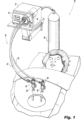
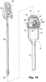
- Fig. 1 a gas circulation system for performing an endoscopic surgical procedure in a surgical cavity of a patient, and more particularly, for performing a robotically assisted laparoscopic surgical procedure in the abdominal cavity of a patient that is constructed in accordance with a preferred embodiment of the subject disclosure and is designated generally by reference numeral 10.
- the gas circulation system 10 of the subject invention is specifically designed to cooperate with a programmable multi-modal gas delivery system 12.
- the gas delivery system 12 is of the type described in commonly assigned U.S. Patent No. 9,375,539 .
- the gas delivery system 12 includes a graphical user interface 14 for setting operating parameters and a pump 16 for facilitating the recirculation of pressurized gas relative to the surgical cavity of the patient.
- the gas delivery system 12 is connected to a source of surgical gas 18 for delivering insufflation gas to the surgical cavity of the patient.
- the gas circulation system 10 includes a multi-lumen filtered tube set 20 having a dual lumen portion 22 and a single lumen portion 24.
- the dual lumen portion 22 of tube set 20 is operatively connected to a gas sealed access cap 26 associated with a second robotic cannula 28.
- the single lumen portion 24 of tube set 20 is operatively connected to a valve sealed access cap 30 associated with a first robotic cannula 32.
- the dual lumen portion 22 of tube set 20 has a pressurized gas line 34 and a return gas line 36 for facilitating gas recirculation relative to the surgical cavity of the patient and for facilitating the evacuation of smoke filled gas from the surgical cavity resulting from electro-cauterization tasks or the like.
- the single lumen portion 24 of tube set 20 defines a gas supply and sensing line 38 that has two distinct functions. It facilitates the delivery of insufflation gas to the surgical cavity of the patient and it also facilitates the periodic sensing of pressure within the surgical cavity of the patient.
- the tube set 20 is operatively associated with a multi-path filter cartridge assembly 40. More particularly, the gas lines of the tube set 20 extend from a fitting 42 on the end cap 44 of the filter cartridge assembly 40.
- a filter cartridge assembly of this type is disclosed for example in commonly assigned U.S. Patent No. 9,067,030 .
- the filter cartridge assembly 40 is preferably designed for a single use and is thereafter disposable. It is specifically designed to cooperate with the multi-modal gas delivery system 12, illustrated in Fig. 1 .
- the filter cartridge assembly 40 includes a first filtered flow passage communicating with the pressurized gas line 34 of the dual lumen portion 22 of the tube set 20, a second filtered flow passage communicating with the return gas line 36 of the dual lumen portion 22 of the tube set 20, and a third filtered flow passage communicating with the gas supply and sensing line 38 of the single lumen portion 24 of the tube set 20.
- the single lumen portion 24 of the tube set 20 includes an enlarged luer type connector fitting 46 for coupling with the valve sealed access cap 30.
- the enlarged luer type connector fitting 46 will be discussed in greater detail below with reference to Fig. 7 and 8 .
- the dual lumen portion 22 of the tube set 20 includes a multi-lumen connector fitting 48 for coupling with the gas sealed access cap portion 26.
- the subject invention describes several different embodiments of a multi-lumen connector fitting 48 for the dual lumen portion 22 of tube set 20.
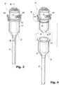
- valve sealed access cap 30 of gas circulation system 10 is adapted and configured for cooperative reception within a proximal bowl portion 50 of the robotic cannula 32, which further includes an elongated tubular body portion 52.
- the valve sealed access cap 30 has an inlet path 54 for communicating with the gas supply and sensing line 38 of the tube set 20. More particularly, as explained in more detail below, the inlet path 54 is a luer type connector that cooperates with the luer type connector fitting 46 on the distal end of the gas supply and sensing line 38.
- the valve sealed access cap 30 includes an elongated generally cylindrical outer housing portion 56 and an elongated generally cylindrical inner body portion 58 that is dimensioned and configured to nest within the outer housing portion 56.
- An annular flow channel 60 is advantageously formed between the outer housing portion 56 and the inner body portion 58 in communication with the inlet path 54.
- An inner O-ring 62 seals the annular channel 60 between the outer housing portion 56 and the inner body portion 58 to provide frictional engagement and prevent gas leakage therebetween.
- the outer housing portion 56 of valve sealed access cap 30 includes a pair of diametrically opposed flexible clips 64a, 64b that are adapted and configured to be releasably latched to an upper annular flange 66 of the proximal bowl portion 50 of robotic cannula 32.
- the flexible clip 64a includes an upper portion 65 that can be readily flexed inwardly to release a lower clip portion 67.
- the opposed flexible clip 64b is similarly constructed.
- An outer O-ring 68 surrounds the periphery of the outer housing portion 56 so that it is positioned between the outer housing portion 56 and the interior wall of the proximal bowl portion 50 of robotic cannula 32 to provide frictional engagement and prevent gas leakage therebetween.
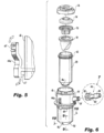
- the inner body portion 58 of the valve sealed access cap 30 supports a primary valve 70 and a secondary valve 72.
- the primary valve 70 is a circular septum valve and the secondary valve 72 is a duckbill valve.
- Other types of mechanical valve seals known in the art can be used as well.
- the primary valve 70 is nested in and located proximal to the secondary valve 72.
- a sound attenuating disc 74 made of a foam material is positioned within the valve sealed access cap 30 proximal to the primary valve 70 for reducing sound levels and to aid in holding the primary valve 70 and secondary valve 72 in place during instrument insertion, removal and manipulation.
- a lid 76 is engaged with a proximal end of the outer housing portion 56 to secure the inner body portion 58 within the outer housing portion 56 and to provide security during instrument insertion, removal and manipulation.
- the lid 76 defines the entryway or inlet port 78 of the access cap 30, through which surgical instruments and the like are introduced into the cannula 32.
- the lid 76 may be mechanically attached to the outer housing portion 56 by clips or tabs or it may be heat welded, spin welded or glued in place.
- the lid 76 further secures the inner body portion 58, the sound attenuating disc 74, the primary valve 70 and the secondary valve 72 within the outer housing portion 56 relative to the inner body portion 58.
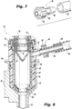
- the inlet path 54 that is integrally formed with the outer housing portion 56 of access cap 30 is a luer type connector.
- it has a thread form 55 that is configured to mate with the luer type connector fitting 46 (See Fig. 6 ).
- the luer type fitting 46 has an elongated stem 80 with a proximal skirt 82 and a barbed distal tip 84.
- the proximal skirt 82 mates with the thread form 55 of inlet path 54, and the distal tip 84 mates with the insufflation and sensing line 38 of the tube set 20.
- the luer type fitting 46 and the inlet path connector 54 are selectively sized to achieve a desired amount of gas flow into the inlet path 54.
- the dimensions or size of these features of the gas circulation system 10 are larger than standard luer type connective fittings that are known and used in the art. This advantageously eliminates a choke point in the flow path of the access cap 30 and maximizes the mass flow rate therethrough for a given driving pressure.
- an inwardly tapered distal end surface 86 of the inner body portion 58 of access cap 30 compressively and intimately engages against an interior distal surface 88 of an inwardly tapered distal wall 90 of the outer housing portion 56 of access cap 30 to enclose the annular gas flow channel 60 in a gas-tight manner.
- the annular channel 60 communicates with the proximal bowl portion 50 of the robotic cannula 32 through a plurality of circumferentially spaced apart nares or openings 92 that are formed in the inwardly tapered distal wall 90 of the outer housing portion 56.
- the plurality of nares 92 are oval shaped and extend radially outwardly from a central axis of the outer housing portion 56.
- the plurality of oval nares 92 can extend generally tangentially relative to a central axis of the outer housing portion.
- a plurality of triangular shaped nares 94 can be provided, which would extend radially outwardly from a central axis of the outer housing portion 56.
- the annular channel 60 communicates with the proximal bowl portion 50 of robotic cannula 32 through an annular nare 96 that is defined between an inwardly tapered distal wall 86 of the inner body portion 58 and the inwardly tapered distal wall 88 of the outer housing portion 56.
- the gas sealed access cap 26 of gas circulation system 10 is adapted and configured for cooperative reception within the proximal bowl portion 110 of robotic cannula 28, which further includes an elongated tubular body portion 112.
- the gas sealed access cap 26 is adapted and configured to cooperate with an obturator 100 for gaining initial access to the abdominal cavity of a patient.
- the obturator 100 includes a proximal handle portion 102 for cooperatively engaging the access cap 26, an elongated tubular shaft 104 dimensioned to extend through the robotic cannula 28 and a sharpened cutting tip 106 for piercing through the abdominal wall.
- the obturator 100 can also be employed with the valve sealed access cap 30 and robotic cannula 32 described above.
- the gas sealed access cap 26 has a multi-lumen connector 114 for communicating with the multi-lumen connector 48 associated with the dual lumen portion 22 of tube set 20.
- the multi-lumen connector 114 is a bi-lumen bullseye connector, which includes a radially outer gas inlet lumen 116 and a central gas outlet lumen 118.
- the gas inlet lumen 116 of connector 114 communicates with the pressurized gas line 34 of the dual lumen portion 22 of the tube set 20, and the gas outlet lumen 118 of connector 114 communicates with the return gas line 36 of the dual lumen portion 22 of the tube set 20.
- the bi-lumen connector 114 extends to a mounting manifold 120 and it includes a plurality of circumferentially spaced apart radially outwardly extending lugs or posts 145 for interacting with the multi-lumen connector fitting 48, as described in more detail below.
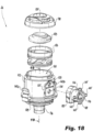
- the gas sealed access cap 28 includes a main housing portion 122 defining an interior cavity 124 that supports a two-piece annular jet assembly 126 for receiving pressurized gas from an inlet port 128 communicating with gas inlet lumen 116 of connector 114.
- the annular jet assembly 126 is adapted and configured to generate a gaseous sealing zone within the robotic cannula 28 to maintain a stable pressure within the surgical cavity of the patient.
- the structure and function of the jet assembly 126 is described in detail in commonly assigned U.S. Patent No. 8,795,223 .
- the main housing portion 122 of access cap 28 includes a mounting flange 125 for cooperatively receiving the manifold 120 of the multi-lumen connector 114.
- a sound attenuating disc 128 made of foam material is positioned within the main housing portion 122 of the gas sealed access cap 26 proximal to the annular jet assembly 126 for reducing sound levels generated by the pressurized gas streaming through the jet assembly 126.
- a lid 130 is engaged with a proximal end of the outer housing portion 122 to secure the annular jet assembly 126 and sound attenuating disc 128 within the main housing portion 122.
- the lid 130 defines the main entry port 135 for the gas sealed access cap 26 through which surgical instruments and the like are introduced into the robotic cannula 28.
- the main housing portion 122 of the gas sealed access cap 26 includes an integrally formed body of circumferentially spaced apart vanes 132 for directing spent gas from the gaseous sealing zone to the outlet lumen 118 of connector 114 by way of an outlet port 134 in the main housing portion 122 of the gas sealed access cap 26.
- This spent gas is withdrawn from the area by the recirculation flow generated by the pump 16 in the multi-modal gas delivery system 12 shown in Fig. 1 .
- the spent gas may include smoke filled gas generated in the surgical cavity.
- the body of integrally formed circumferentially spaced apart vanes 132 surround the inner periphery of the interior cavity 124 of the main housing portion 122 and they extend distally to an inwardly tapered integral tubular extension 136, which extends distally into the proximal bowl portion 110 of robotic cannula 28.
- Similar guide vanes are described in commonly assigned U.S. Patent No. 8,795,223 , but they are not formed integral with a housing.
- An outer O-ring 138 surrounds a lower section of the main housing portion 122 so that it is positioned between the main housing portion 122 of the gas sealed access cap 26 and the proximal bowl portion 110 of robotic cannula 28 to form an air-tight seal therebetween.
- the main housing portion 122 of gas sealed access cap 26 also includes a pair of diametrically opposed flexible clips 140a, 140b that are adapted and configured to be releasably latched to an upper annular flange 142 of the proximal bowl portion 110 of robotic cannula 28, as illustrated for example in Figs. 15 and 16 .
- the multi-lumen connector of the gas sealed access port 26 is a tri-lumen bullseye connector, which is designated generally by reference numeral 214.
- a tri-lumen connector of this type is disclosed in commonly assigned U.S. Patent No. 9,526,886 . This feature is currently employed on commercially available AirSeal access port products that are manufactured and sold by SurgiQuest, Inc., a wholly owned subsidiary of ConMed Corporation, so it is a readily available component. For this reason, it can be easily adapted for use with the gas sealed access cap 26, thus reducing the manufacturing costs and time to market for this new access device.
- the tri-lumen bullseye connector 214 for access cap 26 includes an outer lumen 216 for receiving gas from a pressurized gas line 34, a central lumen 218 for discharging spent gas to the gas return line 36, and an intermediate lumen 217 therebetween.
- the intermediate lumen 217 is not connected to any gas line of the tube set 20, and the inlet area 137 that is located within the bounds of mounting flange 125 is blocked or otherwise blank, thus rendering the intermediate lumen 217 moot.
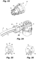
- a bullseye connector fitting for rotatably coupling with the connector 114 of the gas sealed access cap 26 of the subject invention, which is designated generally by reference numeral 150.
- the bullseye connector fitting 150 includes a proximal portion 152 for receiving the dual lumen portion 22 of the tube set 20 and a distal portion 154 for engaging with the spaced apart lugs or posts 145 on the connector 114.
- the distal portion 154 of connector fitting 150 includes a set of generally J-shaped slots 156 for receiving the lugs 145.
- each J-shaped slot 156 has a leading leg section 158 and a trailing foot section 160.
- An enlarged bulb 162 is formed at the entryway to the trailing foot section 158 of slot 156 that must be overcome by rotational force during coupling so that the lug 145 can be locked in place.
- the coupling feature shown in Figs. 23 through 26 can be employed with a bi-lumen connector fitting or a tri-lumen connector fitting in accordance with the subject invention.
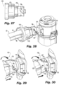
- FIG. 27 through 30 there is illustrated another embodiment of a bullseye connector fitting for rotatably coupling with the connector 114 of the gas sealed access cap 26 of the subject invention, which is designated generally by reference numeral 170.
- the connector fitting 170 includes a proximal portion 172 for receiving the dual lumen portion 22 of the tube set 20 and a distal portion 174 for engaging with the spaced apart lugs or posts 145 on the connector 114.
- the distal portion 174 of connector fitting 170 includes a set of circumferentially spaced apart generally hockey stick shaped slots 176 defining a corkscrew type coupling feature for receiving the lugs 145 and for frictionally retaining the lugs 145 in a locked position within the slots 176 upon clockwise rotation of the fitting 170 relative to the connector 114, as best seen in Figs. 29 and 30 .
- the coupling feature shown in Figs. 27 through 30 can be employed with a bi-lumen connector fitting or a tri-lumen connector fitting in accordance with the subject invention.
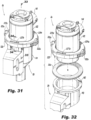
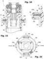
- FIGs. 31 through 36 there is illustrated an attachment mechanism for releasably attaching an embodiment of the gas sealed access cap 26 to the proximal bowl portion 110 of robotic cannula 28, instead of the diametrically opposed flexible clips 140a, 140b previously described herein and shown in Figs. 16 and 17 . More particularly, Figs. 31 through 36 illustrate an oval shaped compressible pinch skirt 220 that is integral with and surrounds the lower section of the main housing portion 122 of the gas sealed access cap 26.
- the compressible pinch skirt 220 has two diametrically opposed compression tabs 222a, 222b and two diametrically opposed clip ledges 223a, 223b with windows 227a, 227b for moldability.
- the compression tabs 222a, 222b are adapted and configured to enable the application of a manual force to the skirt 220 in a radially inward direction, as shown in Fig. 35 . This causes the skirt 220 to expand radially outwardly along an axis that is generally transverse to the force vectors, so that the clip ledges 223a, 223b can be physically released from below the proximal flange 142 of the bowl portion 110 of access cap 26.
- Diametrically opposed C-shaped cutouts 229a, 229b are formed in the pinch skirt 220 adjacent the compression tabs 222a, 222b, respectively, to allow for more displacement of the clip ledges 223a, 223b and to reduce the overall rigidity of the pinch skirt 220.
- a compressible ring 226 is positioned underneath the pinch skirt 220 so that it sits between pinch skirt 220 and the proximal flange 142 of the bowl portion 110, to provide a seal and a resilient biasing force therebetween, enhancing the security of the pinch skirt 220.
- the gasket 226 can be an over-molded elastomer, a flat O-ring or a foam material.
- a spring biased and hinged buckle assembly 230 includes a pair of C-shaped buckle portions 232a, 232b that are hingedly attached to one another about a pivot pin 234, as best seen in Fig. 39 .
- the buckle assembly 230 can be supported on the lower annular flange 224 of the main housing portion 122 of access cap 26, or it could be a separate component.
- the two buckle portions 232a, 232b are normally biased toward one another into a closed and locked position shown in Fig. 37 , by a torsion spring 236 that is associated with pivot pin 234.
- the buckle assembly 230 is adapted and configured for manual movement between an open position shown in Fig. 38 that allows for easy manual separation of the gas sealed access cap 26 from the bowl portion 110 of robotic cannula 28, and the closed position shown in Fig. 37 , wherein the buckle portions 232a, 232b close around the annular flange 224 on the main housing portion 122 of the access cap 26 and the proximal flange 142 of the bowl portion 110 of robotic cannula 28 to securely retain them by way of a friction fit, as best seen in Fig. 40 .
- the buckling attachment feature shown in Figs. 37 through 40 can be employed with the valve sealed access cap 30 in accordance with the subject invention.
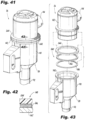
- FIG. 41 through 43 there is illustrated another attachment mechanism for releasably attaching an embodiment of the gas sealed access cap 26 to the proximal bowl portion 110 of robotic cannula 28, which is defined by a magnetic skirt assembly 240.
- the magnetic skirt assembly 240 includes a magnetic ring 242 that can be over-molded onto the underside of the housing flange 224 so that it can interact directly with the metallic proximal flange 142 of the bowl portion 110 of cannula 28, as best seen in Fig. 42 .
- the magnetic ring 242 could be ultrasonically welded between two clipless plastic skirts 244 and 246, and then together the assembly can be secured to the undersurface of annular flange 224 of housing 122, as shown in Fig. 43 .
- the magnetic attachment feature shown in Figs. 41 through 43 can be employed with the valve sealed access cap 30 in accordance with the subject invention.
- FIGs. 44 through 46 there is illustrated an attachment mechanism for releasably attaching an embodiment of the gas sealed access cap 26 to the proximal bowl portion 110 of robotic cannula 28, which is defined by a compressible pinch skirt 250 similar in construction and function to that which is illustrated in Fig. 36 , but in this embodiment of the invention, which is shown schematically, the compressible pinch skirt 250 is inverted and mounted for axial movement relative to the bowl portion 110 of cannula 28, as best shown in Fig. 45 .
- the axially movable inverted pinch skirt 250 can be raised and lowered relative to the bowl portion 110 of robotic cannula 28 to facilitate the releasable attachment of the gas sealed access cap 26 to the robotic cannula 28.
- the movable pinch skirt feature shown in Figs. 44 through 46 can be employed with the valve sealed access cap 30 in accordance with the subject invention.
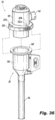
- a tri-lumen bullseye plug 260 that is adapted and configured to intimately mate with the tri-lumen bullseye connector fitting 248 associated with the dual lumen portion 22 of tube set 20, shown in Fig. 22 .
- the bullseye plug 260 is utilized when the dual lumen portion 22 of tube set 20 is not being employed, but the single lumen portion 24 of tube set 20 is being employed, such as, for example, during an initial insufflation stage of a robotically assisted surgical procedure.
- the bullseye plug 260 creates a negative pressure in the dual lumen portion 22 of tube set 20 that indicates to a pressure sensor in the gas delivery system 12 that a standard insufflation mode is underway. At such a time, the pump 16 within the gas delivery system 12 will be inactive.
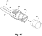
- Fig. 48 there is illustrated in fine detail the Da Vinci robotic cannula 28 employed with the gas sealed access cap 26 of the subject invention, as previously illustrated for example in Fig. 1 .
- the elongated body portion 112 of robotic cannula 28 has an internal bore 115 with an inner diameter D that is about 8.89 mm, and it is dimensioned to accommodate the shaft of a robotic instrument having an outer diameter of about 8.55 mm, which is not shown. This allows for a 0.39 mm gap therebetween for gas flow. However, a greater gap is needed for the gas sealed access cap 26 to function effectively.
- a cannula with a larger inner diameter is required, so that pressurized gas can flow more readily between the inner periphery of the internal bore 115 and the outer periphery of a robotic instrument extending therethrough.
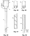
- Fig. 49 illustrates a robotic cannula body 270 having a set of circumferentially spaced apart linear beads 272 that are formed or otherwise provided on the interior surface thereof to provide enhanced gas flow for the gas sealed access cap 26.
- Fig. 50 illustrates a robotic cannula body 280 having a set of circumferentially spaced apart linear channels 284 that are formed in the interior surface thereof to provide enhanced gas flow for the gas sealed access cap 26.
- FIG. 51 illustrates a robotic cannula body 290 having a continuous helical bead 292 that is formed or otherwise provided on the interior surface thereof to provide enhanced gas flow between the interior wall of the cannula body 290 and a robotic instrument 300 extending therethrough, as best seen in Fig. 52 .
- a robotic cannula body could also provide enhanced gas flow when used in conjunction with the valve sealed access cap 30.
Landscapes
- Health & Medical Sciences (AREA)
- Life Sciences & Earth Sciences (AREA)
- Surgery (AREA)
- Engineering & Computer Science (AREA)
- Heart & Thoracic Surgery (AREA)
- Animal Behavior & Ethology (AREA)
- General Health & Medical Sciences (AREA)
- Public Health (AREA)
- Veterinary Medicine (AREA)
- Biomedical Technology (AREA)
- Nuclear Medicine, Radiotherapy & Molecular Imaging (AREA)
- Medical Informatics (AREA)
- Molecular Biology (AREA)
- Pathology (AREA)
- Robotics (AREA)
- Anesthesiology (AREA)
- Hematology (AREA)
- Pulmonology (AREA)
- Oral & Maxillofacial Surgery (AREA)
- Surgical Instruments (AREA)
- Endoscopes (AREA)
- Manipulator (AREA)
Claims (23)
- Gaszirkulationssystem (10) zum Durchführen robotergestützter chirurgischer Eingriffe in einem Operationshohlraum eines Patienten, umfassend:a) einen Mehrlumen-Schlauchsatz (20), der einen Doppellumenabschnitt (22) mit einer Druckgasleitung (34) und einer Gasrückführungsleitung (36) zum Ermöglichen einer Gasrückführung relativ zum Operationshohlraum des Patienten umfasst, und einen einzelnen Lumenabschnitt (24) mit einer Gaszuführungs- und Messleitung (38) zum Zuführen von Insufflationsgas zur Bauchhohlraum des Patienten und zum periodischen Messen eines Drucks innerhalb des Operationshohlraumes des Patienten;b) eine ventilabgedichtete Zugangskappe (30), die zur kooperativen Aufnahme innerhalb eines proximalen Schalenabschnitts (50) einer ersten Roboterkanüle (32) angepasst und eingerichtet ist und einen Einlassweg (54) zur Verbindung mit der Gaszuführungs- und Messleitung (38) des Schlauchsatzes (20) aufweist; undc) eine gasabgedichtete Zugangskappe (26), die zur kooperativen Aufnahme innerhalb eines proximalen Schalenabschnitts (110) einer zweiten Roboterkanüle (28) angepasst und eingerichtet ist und einen Einlassweg zur Verbindung mit der Druckgasleitung (34) des Schlauchsatzes (20) und einen Auslassweg zur Verbindung mit der Gasrückführungsleitung (36) des Schlauchsatzes (20) aufweist,wobei die ventilabgedichtete Zugangskappe (30) einen äußeren Gehäuseabschnitt (56) und einen inneren Körperabschnitt (58) umfasst und wobei ein ringförmiger Kanal (60) zwischen dem äußeren Gehäuseabschnitt (56) und dem inneren Körperabschnitt (58) in Verbindung mit dem Einlassweg (54) ausgebildet ist.
- Gaszirkulationssystem (10) nach Anspruch 1, wobei der äußere Gehäuseabschnitt (56) ein Paar diametral gegenüberliegender flexibler Klammern (64a, 64b) umfasst, die angepasst und eingerichtet sind, um lösbar am proximalen Schalenabschnitt (50) der ersten Roboterkanüle (32) verriegelt zu werden, oder- wobei ein innerer O-Ring (62) den ringförmigen Kanal (60) zwischen dem äußeren Gehäuseabschnitt (56) und dem inneren Körperabschnitt (58) abdichtet, um einen Gasaustritt zu verhindern, oder- wobei ein äußerer O-Ring (62) zwischen dem äußeren Gehäuseabschnitt (56) und dem proximalen Schalenabschnitt (50) der ersten Roboterkanüle (32) positioniert ist, um einen Reibungseingriff vorzusehen und einen Gasaustritt dazwischen zu verhindern.
- Gaszirkulationssystem (10) nach Anspruch 1, wobei im inneren Körperabschnitt (58) der ventilabgedichteten Zugangskappe (30) ein Primärventil (70) und ein Sekundärventil (72) gelagert sind.
- Gaszirkulationssystem (10) nach Anspruch 3, wobei das Primärventil (70) ein kreisförmiges Septumventil ist und das Sekundärventil (72) ein Entenschnabelventil ist, und insbesondere
wobei das Primärventil (70) proximal zum Sekundärventil (72) angeordnet ist. - Gaszirkulationssystem (10) nach Anspruch 3, wobei ein schalldämpfendes Schaumstoffmaterial innerhalb der ventilabgedichteten Zugangskappe (30) proximal zum Primärventil (70) positioniert ist, um den Schallpegel zu reduzieren und das Primärventil (70) und das Sekundärventil (72) während des Einsetzens, Entfernens und der Handhabung des Instruments in Position zu halten.
- Gaszirkulationssystem (10) nach Anspruch 5, wobei ein Deckel (76) mit einem proximalen Ende des äußeren Gehäuseabschnitts (56) in Eingriff steht, um den inneren Körperabschnitt (58) innerhalb des äußeren Gehäuseabschnitts zu sichern (56), um das Primärventil (70) und das Sekundärventil (72) während des Einsetzens, Entfernens und der Handhabung des Instruments in Position zu sichern,
und wobei insbesondere der Deckel (76) ferner den inneren Körperabschnitt (58), das schalldämpfende Schaumstoffmaterial, das Primärventil (70) und das Sekundärventil (72) innerhalb des äußeren Gehäuseabschnitts (56) relativ zum inneren Körperabschnitt sichert. - Gaszirkulationssystem (10) nach Anspruch 1,- wobei der Einlassweg (54) mit dem äußeren Gehäuseabschnitt (56) ausgebildet ist und ein Luer-Anschluss zum Verbinden mit der Gaszuführungs- und Messleitung (38) des Schlauchsatzes (20) damit wirkverbunden ist, und wobei der Luer-Anschluss selektiv dimensioniert ist, um eine gewünschte Menge an Gasstrom in den Einlassweg (54) zu erreichen, oder- wobei der ringförmige Kanal (60) mit dem proximalen Schalenabschnitt (50) der ersten Roboterkanüle (32) über ein ringförmiges Loch (96) verbunden ist, die zwischen einer sich nach innen verjüngenden distalen Wand (86) des inneren Körperabschnitts (56) und einer sich nach innen verjüngenden distalen Wand (90) des äußeren Gehäuseabschnitts (56) ausgebildet ist.
- Gaszirkulationssystem (10) nach Anspruch 1, wobei eine distale Endfläche des inneren Körperabschnitts (58) durch Kompression an einer inneren distalen Fläche (88) einer sich nach innen verjüngenden distalen Wand (90) des äußeren Gehäuseabschnitts (56) anliegt, um den ringförmigen Kanal (60) zu umschlie-ßen.
- Gaszirkulationssystem (10) nach Anspruch 8, wobei der ringförmige Kanal (60) mit dem proximalen Schalenabschnitt (50) der ersten Roboterkanüle (32) über eine Mehrzahl von in Umfangsrichtung voneinander beabstandeten Löchern (92) verbunden ist, die in der sich nach innen verjüngenden distalen Wand (90) des äußeren Gehäuseabschnitts (56) ausgebildet sind, und wobei die Anzahl und/oder die Größe der Löcher (92) ausgewählt wird, um einen gewünschten Gasstrom zu erreichen.
- Gaszirkulationssystem (10) nach Anspruch 9, wobei die Mehrzahl von Löchern (92) oval geformt ist und sich von einer Mittelachse des äußeren Gehäuseabschnitts (56) radial nach außen erstreckt, oder- wobei die Mehrzahl von Löchern (92) oval geformt ist und sich im Wesentlichen tangential relativ zu einer Mittelachse des äußeren Gehäuseabschnitts (56) erstreckt, oder- wobei die Mehrzahl von Löchern (92) dreieckig geformt ist und sich von einer Mittelachse des äußeren Gehäuseabschnitts (56) radial nach außen erstreckt.
- Gaszirkulationssystem (10) nach Anspruch 1, das ferner einen Obturator (100) zur Verwendung mit einer der Zugangskappen aufweist und einen länglichen röhrenförmigen Schaft (104) mit einer distalen Schneidspitze (106) aufweist.
- Gaszirkulationssystem (10) nach Anspruch 1, wobei die gasdichte Zugangskappe (26) einen Hauptgehäuseabschnitt (122) umfasst, der einen inneren Hohlraum (124) bildet, der eine ringförmige Düsenanordnung (126) zur Aufnahme von Druckgas aus dem Einlassweg und zur Erzeugung eines gasförmigen Dichtungsbereichs innerhalb der zweiten Roboterkanüle (28) trägt, um einen stabilen Druck innerhalb des Operationshohlraumes des Patienten aufrechtzuerhalten.
- Gaszirkulationssystem (10) nach Anspruch 12, wobei ein schalldämpfendes Schaummaterial innerhalb der gasdichten Zugangskappe (26), proximal zur ringförmigen Düsenanordnung (126), zum Reduzieren des Schallpegels positioniert ist, und insbesondere
wobei ein Deckel (130) mit einem proximalen Ende des Hauptgehäuseabschnitts (122) in Eingriff steht, um die ringförmige Düsenanordnung (126) und das schalldämpfende Schaumstoffmaterial innerhalb des Hauptgehäuseabschnitts (122) zu sichern. - Gaszirkulationssystem (10) nach Anspruch 12, wobei der Hauptgehäuseabschnitt (122) einen einstückig geformten Satz von in Umfangsrichtung voneinander beabstandeten Flügeln (132) umfasst, um Gas vom gasdichten Bereich zum Auslassweg der gasdichten Zugangskappe (26) zu leiten, und insbesondere wobei sich der Satz von in Umfangsrichtung voneinander beabstandeten Flügeln (132) distal erstreckt, um eine röhrenförmige Verlängerung (136) zu bilden, die sich in den proximalen Schalenabschnitt (110) der zweiten Roboterkanüle (28) erstreckt.
- Gaszirkulationssystem (10) nach Anspruch 12, wobei ein äußerer O-Ring (138) zwischen dem Hauptgehäuseabschnitt (122) der gasdichten Zugangskappe (26) und dem proximalen Schalenabschnitt (110) der zweiten Roboterkanüle (28) positioniert ist.
- Gaszirkulationssystem (10) nach Anspruch 12, wobei der Einlassweg und der Auslassweg der gasdichten Zugangskappe (26) mit einem Verteiler (120) verbunden sind, der mit einem Bullseye-Anschlussfitting zur Verbindung mit der Druckgasleitung und der Gasrückführungsleitung des Schlauchsatzes (20) verbunden ist, wobei das Bullseye-Anschlussfitting eine Mehrzahl von in Umfangsrichtung beabstandeten, sich radial nach außen erstreckenden Eingriffsnasen (145) aufweist, die daran ausgebildet sind.
- Gaszirkulationssystem (10) nach Anspruch 16, wobei das Bullseye-Anschlussfitting ein zweilumiges Bullseye-Anschlussfitting zur Verbindung mit der Druckgasleitung (34) und der Gasrückführungsleitung (36) des Schlauchsatzes (20) ist.
- Gaszirkulationssystem (10) nach Anspruch 16, wobei das Bullseye-Anschlussfitting ein dreilumiges Bullseye-Anschlussfitting zur Verbindung mit der Druckgasleitung (34) und der Gasrückführungsleitung (36) des Schlauchsatzes (20), nicht jedoch mit der Gaszuführungs- und Messleitung (38) des Schlauchsatzes (20) ist.
- Gaszirkulationssystem (10) nach Anspruch 16, wobei der Doppellumenabschnitt (22) des Schlauchsatzes (20) eine Kupplung mit darin ausgebildeten, in Umfangsrichtung angeordneten bajonettartigen Befestigungskanälen zum mechanischen Eingriff mit den Eingriffsnasen (145) des Bullseye-Anschlussfittings umfasst, oder
wobei der Doppellumenabschnitt (22) des Schlauchsatzes (20) eine Kupplung mit darin ausgebildeten, spiralförmig angeordneten bajonettartigen Befestigungskanälen zum mechanischen Eingriff mit den Eingriffsnasen (145) des Bullseye-Anschlussfittings umfasst. - Gaszirkulationssystem (10) nach Anspruch 12, wobei der Hauptgehäuseabschnitt (122) der gasdichten Zugangskappe (26) ein Paar von diametral gegenüberliegenden flexiblen Klammern umfasst, die angepasst und eingerichtet sind, um lösbar am proximalen Schalenabschnitt (110) der zweiten Roboterkanüle (28) verriegelt zu werden.
- Gaszirkulationssystem (10) nach Anspruch 12,- wobei der Hauptgehäuseabschnitt (122) der gasdichten Zugangskappe (26) eine komprimierbare ringförmige Einfassung umfasst, die angepasst und eingerichtet ist, um lösbar am proximalen Schalenabschnitt (110) der zweiten Roboterkanüle (28) verriegelt zu werden, oder- wobei der proximale Schalenabschnitt (110) der zweiten Roboterkanüle (28) eine bewegliche, komprimierbare, ringförmige Einfassung umfasst, die angepasst und eingerichtet ist, um lösbar am Hauptgehäuseabschnitt (122) der gasdichten Zugangskappe (26) verriegelt zu werden, oder- wobei der Hauptgehäuseabschnitt (122) der gasdichten Zugangskappe (26) eine federvorgespannte Klappschnalle (230) umfasst, die angepasst und eingerichtet ist, um lösbar am proximalen Schalenabschnitt (110) der zweiten Roboterkanüle (28) verriegelt zu werden, oder- wobei der Hauptgehäuseabschnitt (122) der gasdichten Zugangskappe (26) eine magnetische Einfassung (240) umfasst, die angepasst ist, um lösbar am proximalen Schalenabschnitt (110) der zweiten Roboterkanüle (28) befestigt zu werden.
- Gaszirkulationssystem (10) nach Anspruch 18, wobei das Tri-Lumen-Bullseye-Anschlussfitting angepasst und eingerichtet ist, um mit einer Tri-Lumen-Bullseye-Kupplung in Verbindung zu sein, die mit dem distalen Ende des Doppellumenabschnitts (22) des Schlauchsatzes (20) verbunden ist, und insbesondere mit einem Tri-Lumen-Bullseye-Stecker (260) für den Eingriff mit der Tri-Lumen-Bullseye-Kupplung verbunden ist.
- Gaszirkulationssystem (10) nach Anspruch 1,- wobei die zweite Roboterkanüle (28) einen länglichen röhrenförmigen Körperabschnitt (112) aufweist, der sich distal von ihrem proximalen Schalenabschnitt (110) erstreckt, der eine Mehrzahl von in Umfangsrichtung voneinander beabstandeten Längswülsten (272) auf einer Innenfläche davon umfasst, um den Gasstrom um ein chirurgisches Instrument herum aufzunehmen, das sich durch den röhrenförmigen Körperabschnitt (112) erstreckt, oder- wobei die zweite Roboterkanüle (28) einen länglichen röhrenförmigen Körperabschnitt (112) aufweist, der sich distal von ihrem proximalen Schalenabschnitt (110) erstreckt, der eine Mehrzahl von in Umfangsrichtung voneinander beabstandeten Längskanälen (284) innerhalb einer Innenfläche davon umfasst, um den Gasstrom um ein chirurgisches Instrument herum aufzunehmen, das sich durch den röhrenförmigen Körperabschnitt (112) erstreckt, oder- wobei die zweite Roboterkanüle (28) einen länglichen röhrenförmigen Körperabschnitt (112) aufweist, der sich distal von ihrem proximalen Schalenabschnitt (110) erstreckt, der einen spiralförmigen Wulst (292) an seiner Innenfläche davon aufweist, um den Gasstrom um ein chirurgisches Instrument herum aufzunehmen, das sich durch den röhrenförmigen Körperabschnitt (112) erstreckt.
Priority Applications (1)
| Application Number | Priority Date | Filing Date | Title |
|---|---|---|---|
| EP24166432.5A EP4364783A3 (de) | 2019-03-26 | 2020-03-25 | Gaszirkulationssystem mit gasabgedichteter zugangskappe und ventilabgedichteter zugangskappe für robotergestützte chirurgische eingriffe |
Applications Claiming Priority (4)
| Application Number | Priority Date | Filing Date | Title |
|---|---|---|---|
| US201962823848P | 2019-03-26 | 2019-03-26 | |
| US201962876141P | 2019-07-19 | 2019-07-19 | |
| US201962925424P | 2019-10-24 | 2019-10-24 | |
| PCT/US2020/024711 WO2020198355A1 (en) | 2019-03-26 | 2020-03-25 | Gas circulation system with gas sealed access cap and valve sealed access cap for robotically assisted surgical procedures |
Related Child Applications (2)
| Application Number | Title | Priority Date | Filing Date |
|---|---|---|---|
| EP24166432.5A Division-Into EP4364783A3 (de) | 2019-03-26 | 2020-03-25 | Gaszirkulationssystem mit gasabgedichteter zugangskappe und ventilabgedichteter zugangskappe für robotergestützte chirurgische eingriffe |
| EP24166432.5A Division EP4364783A3 (de) | 2019-03-26 | 2020-03-25 | Gaszirkulationssystem mit gasabgedichteter zugangskappe und ventilabgedichteter zugangskappe für robotergestützte chirurgische eingriffe |
Publications (3)
| Publication Number | Publication Date |
|---|---|
| EP3946527A1 EP3946527A1 (de) | 2022-02-09 |
| EP3946527A4 EP3946527A4 (de) | 2022-11-23 |
| EP3946527B1 true EP3946527B1 (de) | 2024-05-29 |
Family
ID=72606239
Family Applications (2)
| Application Number | Title | Priority Date | Filing Date |
|---|---|---|---|
| EP20778743.3A Active EP3946527B1 (de) | 2019-03-26 | 2020-03-25 | Gaszirkulationssystem mit gasabdgedichteter zugangskappe und ventilabgedichteter zugangskappe für robotergestützte chirurgische verfahren |
| EP24166432.5A Pending EP4364783A3 (de) | 2019-03-26 | 2020-03-25 | Gaszirkulationssystem mit gasabgedichteter zugangskappe und ventilabgedichteter zugangskappe für robotergestützte chirurgische eingriffe |
Family Applications After (1)
| Application Number | Title | Priority Date | Filing Date |
|---|---|---|---|
| EP24166432.5A Pending EP4364783A3 (de) | 2019-03-26 | 2020-03-25 | Gaszirkulationssystem mit gasabgedichteter zugangskappe und ventilabgedichteter zugangskappe für robotergestützte chirurgische eingriffe |
Country Status (9)
| Country | Link |
|---|---|
| US (3) | US11399866B2 (de) |
| EP (2) | EP3946527B1 (de) |
| JP (1) | JP7289368B2 (de) |
| KR (2) | KR102720117B1 (de) |
| CN (2) | CN116687529A (de) |
| AU (2) | AU2020244820B2 (de) |
| CA (2) | CA3133315C (de) |
| ES (1) | ES2984305T3 (de) |
| WO (1) | WO2020198355A1 (de) |
Families Citing this family (11)
| Publication number | Priority date | Publication date | Assignee | Title |
|---|---|---|---|---|
| US10905463B2 (en) | 2017-03-08 | 2021-02-02 | Conmed Corporation | Gas circulation system with single lumen gas sealed access port and single lumen valve sealed access port for use during endoscopic surgical procedures |
| WO2020198355A1 (en) | 2019-03-26 | 2020-10-01 | Conmed Corporation | Gas circulation system with gas sealed access cap and valve sealed access cap for robotically assisted surgical procedures |
| USD933836S1 (en) * | 2019-05-15 | 2021-10-19 | Tinavi Medical Technologies Co., Ltd. | Tracer |
| US11849969B2 (en) * | 2020-12-04 | 2023-12-26 | Covidien Lp | Cannula with smoke evacuation housing |
| US11904087B2 (en) | 2021-02-17 | 2024-02-20 | Conmed Corporation | Passive surgical access port filtration fittings |
| CA3201735A1 (en) * | 2021-03-08 | 2022-09-15 | Michael L. Koltz, Jr. | Solenoids for insufflation systems |
| US11903611B2 (en) * | 2021-05-05 | 2024-02-20 | Conmed Corporation | Active surgical access port filtration fittings |
| WO2023009694A1 (en) * | 2021-07-30 | 2023-02-02 | Conmed Corporation | Gas sealed access cap for a robotic cannula and method of performing a robotically assisted surgical procedure |
| JP7713594B2 (ja) * | 2021-11-15 | 2025-07-25 | コンメッド コーポレーション | 外科手術用ロボットでの使用のためのアクセスポート |
| CN114533218A (zh) * | 2022-02-22 | 2022-05-27 | 上海微创医疗机器人(集团)股份有限公司 | 穿刺器、内套管装置及密封结构 |
| CN121666210A (zh) * | 2023-08-09 | 2026-03-13 | 柯惠有限合伙公司 | 模块化插管组件 |
Family Cites Families (30)
| Publication number | Priority date | Publication date | Assignee | Title |
|---|---|---|---|---|
| US7338473B2 (en) * | 2003-04-08 | 2008-03-04 | Surgiquest, Incorporated | Pneumoseal trocar arrangement |
| US7182752B2 (en) * | 2003-04-08 | 2007-02-27 | Surgiquest, Incorporated | Continuous gas flow trocar assembly |
| US7854724B2 (en) | 2003-04-08 | 2010-12-21 | Surgiquest, Inc. | Trocar assembly with pneumatic sealing |
| US7285112B2 (en) * | 2003-04-08 | 2007-10-23 | Surgiquest, Incorporated | Gas flow trocar arrangement |
| US7608082B2 (en) | 2005-01-06 | 2009-10-27 | Tyco Healthcare Group Lp | Surgical seal for use in a surgical access apparatus |
| US7717878B2 (en) * | 2005-04-25 | 2010-05-18 | Tyco Healthcare Group Lp | Surgical portal with seal system |
| AU2009222028A1 (en) * | 2008-03-03 | 2009-09-11 | Applied Medical Resources Corporation | Balloon trocar advanced fixation |
| EP2328487B1 (de) * | 2008-09-29 | 2018-04-18 | Applied Medical Resources Corporation | Trokarsystem für den ersten zutritt |
| JP5733831B2 (ja) * | 2008-10-10 | 2015-06-10 | サージクェスト,インコーポレーテッド | 気体封止機構を備えた手術用トロカールにおけるガス再循環向上のためのシステム及び方法 |
| ES2728227T3 (es) * | 2009-10-10 | 2019-10-23 | Surgiquest Incorporated | Dispositivos de acceso quirúrgicos de perfil bajo |
| WO2012005819A1 (en) * | 2010-05-24 | 2012-01-12 | Surgiquest, Incorporated | Devices for automated surgery |
| WO2012044410A2 (en) | 2010-09-20 | 2012-04-05 | Surgiquest, Inc. | Multi-flow filtration system |
| WO2012122263A2 (en) | 2011-03-08 | 2012-09-13 | Surgiquest, Inc. | Trocar assembly with pneumatic sealing |
| US9149178B2 (en) * | 2012-03-26 | 2015-10-06 | Covidien Lp | Surgical access assembly and method of use therefor |
| US9017281B2 (en) * | 2012-09-07 | 2015-04-28 | Surgiquest, Inc. | System having multiple pneumatically sealed trocars |
| CN110338910B (zh) * | 2012-11-20 | 2022-11-29 | 瑟吉奎斯特公司 | 用于在腹腔镜外科手术过程期间进行烟气抽空的系统及方法 |
| US9526886B2 (en) | 2012-12-19 | 2016-12-27 | Surgiquest, Inc. | Coupling for connecting a tube set to a trocar |
| US20150031958A1 (en) * | 2013-07-25 | 2015-01-29 | Covidien Lp | Surgical seal assembly with upper lip seal |
| US9700303B2 (en) * | 2013-08-02 | 2017-07-11 | Covidien Lp | Devices, systems, and methods for providing surgical access and facilitating closure of surgical access openings |
| KR102507087B1 (ko) | 2014-03-17 | 2023-03-07 | 인튜어티브 서지컬 오퍼레이션즈 인코포레이티드 | 캐뉼라 실 어셈블리 |
| US9888942B1 (en) * | 2014-12-19 | 2018-02-13 | Ethicon Llc | Adaptor for robotics cannula and seal assembly |
| US9801656B2 (en) * | 2015-01-30 | 2017-10-31 | Surgiquest, Inc. | Self-adjusting pneumatically sealed trocar |
| US9387295B1 (en) * | 2015-01-30 | 2016-07-12 | SurgiQues, Inc. | Filter cartridge with internal gaseous seal for multimodal surgical gas delivery system having a smoke evacuation mode |
| US10869691B2 (en) * | 2017-03-08 | 2020-12-22 | Conmed Corporation | Flexible single lumen gas sealed access port for use during robotically assisted endoscopic surgical procedures |
| US10905463B2 (en) * | 2017-03-08 | 2021-02-02 | Conmed Corporation | Gas circulation system with single lumen gas sealed access port and single lumen valve sealed access port for use during endoscopic surgical procedures |
| EP3717055B1 (de) * | 2017-12-01 | 2025-09-03 | Merit Medical Systems, Inc. | Hämostatisches ventilsystem |
| US20210015572A1 (en) * | 2018-03-29 | 2021-01-21 | Intuitive Surgical Operations, Inc. | Surgical instrument actuation systems |
| US20200205855A1 (en) * | 2019-01-02 | 2020-07-02 | Covidien Lp | Surgical access device and sleeve stops for use therewith |
| WO2020198355A1 (en) | 2019-03-26 | 2020-10-01 | Conmed Corporation | Gas circulation system with gas sealed access cap and valve sealed access cap for robotically assisted surgical procedures |
| US11484337B2 (en) * | 2020-02-06 | 2022-11-01 | Covidien Lp | Surgical access device including anchor with rachet mechanism |
-
2020
- 2020-03-25 WO PCT/US2020/024711 patent/WO2020198355A1/en not_active Ceased
- 2020-03-25 KR KR1020247024839A patent/KR102720117B1/ko active Active
- 2020-03-25 AU AU2020244820A patent/AU2020244820B2/en active Active
- 2020-03-25 CN CN202310799976.9A patent/CN116687529A/zh active Pending
- 2020-03-25 CN CN202080023652.0A patent/CN113660969B/zh active Active
- 2020-03-25 US US16/829,694 patent/US11399866B2/en active Active
- 2020-03-25 CA CA3133315A patent/CA3133315C/en active Active
- 2020-03-25 EP EP20778743.3A patent/EP3946527B1/de active Active
- 2020-03-25 CA CA3210789A patent/CA3210789A1/en active Pending
- 2020-03-25 KR KR1020217033940A patent/KR102689313B1/ko active Active
- 2020-03-25 JP JP2021557351A patent/JP7289368B2/ja active Active
- 2020-03-25 EP EP24166432.5A patent/EP4364783A3/de active Pending
- 2020-03-25 ES ES20778743T patent/ES2984305T3/es active Active
-
2022
- 2022-06-16 US US17/841,865 patent/US12004774B2/en active Active
- 2022-12-22 AU AU2022291578A patent/AU2022291578B2/en active Active
-
2024
- 2024-05-20 US US18/668,669 patent/US12502204B2/en active Active
Also Published As
| Publication number | Publication date |
|---|---|
| AU2020244820A1 (en) | 2021-09-30 |
| US20220304724A1 (en) | 2022-09-29 |
| ES2984305T3 (es) | 2024-10-29 |
| EP3946527A4 (de) | 2022-11-23 |
| CA3133315A1 (en) | 2020-10-01 |
| KR102720117B1 (ko) | 2024-10-22 |
| CA3210789A1 (en) | 2020-10-01 |
| CN116687529A (zh) | 2023-09-05 |
| KR102689313B1 (ko) | 2024-07-30 |
| JP2022527274A (ja) | 2022-06-01 |
| EP3946527A1 (de) | 2022-02-09 |
| CN113660969B (zh) | 2023-07-21 |
| AU2022291578B2 (en) | 2025-02-06 |
| KR20210130837A (ko) | 2021-11-01 |
| EP4364783A3 (de) | 2024-07-17 |
| AU2022291578A1 (en) | 2023-02-02 |
| KR20240118191A (ko) | 2024-08-02 |
| US20200305928A1 (en) | 2020-10-01 |
| US20240299060A1 (en) | 2024-09-12 |
| CA3133315C (en) | 2023-10-17 |
| AU2020244820B2 (en) | 2022-09-22 |
| WO2020198355A1 (en) | 2020-10-01 |
| CN113660969A (zh) | 2021-11-16 |
| US12004774B2 (en) | 2024-06-11 |
| US12502204B2 (en) | 2025-12-23 |
| US11399866B2 (en) | 2022-08-02 |
| EP4364783A2 (de) | 2024-05-08 |
| JP7289368B2 (ja) | 2023-06-09 |
Similar Documents
| Publication | Publication Date | Title |
|---|---|---|
| AU2022291578B2 (en) | Gas circulation system with gas sealed access cap and valve sealed access cap for robotically assisted surgical procedures | |
| US11974774B2 (en) | Separable two-part single lumen gas sealed access port for use during endoscopic surgical procedures |
Legal Events
| Date | Code | Title | Description |
|---|---|---|---|
| STAA | Information on the status of an ep patent application or granted ep patent |
Free format text: STATUS: THE INTERNATIONAL PUBLICATION HAS BEEN MADE |
|
| PUAI | Public reference made under article 153(3) epc to a published international application that has entered the european phase |
Free format text: ORIGINAL CODE: 0009012 |
|
| STAA | Information on the status of an ep patent application or granted ep patent |
Free format text: STATUS: REQUEST FOR EXAMINATION WAS MADE |
|
| 17P | Request for examination filed |
Effective date: 20210913 |
|
| AK | Designated contracting states |
Kind code of ref document: A1 Designated state(s): AL AT BE BG CH CY CZ DE DK EE ES FI FR GB GR HR HU IE IS IT LI LT LU LV MC MK MT NL NO PL PT RO RS SE SI SK SM TR |
|
| DAV | Request for validation of the european patent (deleted) | ||
| DAX | Request for extension of the european patent (deleted) | ||
| A4 | Supplementary search report drawn up and despatched |
Effective date: 20221026 |
|
| RIC1 | Information provided on ipc code assigned before grant |
Ipc: A61B 18/12 20060101ALN20221020BHEP Ipc: A61M 39/06 20060101ALI20221020BHEP Ipc: A61B 34/30 20160101ALI20221020BHEP Ipc: A61B 17/34 20060101ALI20221020BHEP Ipc: A61M 13/00 20060101AFI20221020BHEP |
|
| P01 | Opt-out of the competence of the unified patent court (upc) registered |
Effective date: 20230921 |
|
| GRAP | Despatch of communication of intention to grant a patent |
Free format text: ORIGINAL CODE: EPIDOSNIGR1 |
|
| STAA | Information on the status of an ep patent application or granted ep patent |
Free format text: STATUS: GRANT OF PATENT IS INTENDED |
|
| RIC1 | Information provided on ipc code assigned before grant |
Ipc: A61B 90/00 20160101ALN20231218BHEP Ipc: A61B 18/12 20060101ALN20231218BHEP Ipc: A61M 39/06 20060101ALI20231218BHEP Ipc: A61B 34/30 20160101ALI20231218BHEP Ipc: A61B 17/34 20060101ALI20231218BHEP Ipc: A61M 13/00 20060101AFI20231218BHEP |
|
| INTG | Intention to grant announced |
Effective date: 20240109 |
|
| GRAS | Grant fee paid |
Free format text: ORIGINAL CODE: EPIDOSNIGR3 |
|
| GRAA | (expected) grant |
Free format text: ORIGINAL CODE: 0009210 |
|
| STAA | Information on the status of an ep patent application or granted ep patent |
Free format text: STATUS: THE PATENT HAS BEEN GRANTED |
|
| AK | Designated contracting states |
Kind code of ref document: B1 Designated state(s): AL AT BE BG CH CY CZ DE DK EE ES FI FR GB GR HR HU IE IS IT LI LT LU LV MC MK MT NL NO PL PT RO RS SE SI SK SM TR |
|
| REG | Reference to a national code |
Ref country code: CH Ref legal event code: EP |
|
| REG | Reference to a national code |
Ref country code: IE Ref legal event code: FG4D |
|
| REG | Reference to a national code |
Ref country code: DE Ref legal event code: R096 Ref document number: 602020031706 Country of ref document: DE |
|
| REG | Reference to a national code |
Ref country code: LT Ref legal event code: MG9D |
|
| REG | Reference to a national code |
Ref country code: NL Ref legal event code: MP Effective date: 20240529 |
|
| PG25 | Lapsed in a contracting state [announced via postgrant information from national office to epo] |
Ref country code: IS Free format text: LAPSE BECAUSE OF FAILURE TO SUBMIT A TRANSLATION OF THE DESCRIPTION OR TO PAY THE FEE WITHIN THE PRESCRIBED TIME-LIMIT Effective date: 20240929 |
|
| PG25 | Lapsed in a contracting state [announced via postgrant information from national office to epo] |
Ref country code: BG Free format text: LAPSE BECAUSE OF FAILURE TO SUBMIT A TRANSLATION OF THE DESCRIPTION OR TO PAY THE FEE WITHIN THE PRESCRIBED TIME-LIMIT Effective date: 20240529 |
|
| PG25 | Lapsed in a contracting state [announced via postgrant information from national office to epo] |
Ref country code: HR Free format text: LAPSE BECAUSE OF FAILURE TO SUBMIT A TRANSLATION OF THE DESCRIPTION OR TO PAY THE FEE WITHIN THE PRESCRIBED TIME-LIMIT Effective date: 20240529 Ref country code: FI Free format text: LAPSE BECAUSE OF FAILURE TO SUBMIT A TRANSLATION OF THE DESCRIPTION OR TO PAY THE FEE WITHIN THE PRESCRIBED TIME-LIMIT Effective date: 20240529 |
|
| PG25 | Lapsed in a contracting state [announced via postgrant information from national office to epo] |
Ref country code: GR Free format text: LAPSE BECAUSE OF FAILURE TO SUBMIT A TRANSLATION OF THE DESCRIPTION OR TO PAY THE FEE WITHIN THE PRESCRIBED TIME-LIMIT Effective date: 20240830 |
|
| REG | Reference to a national code |
Ref country code: AT Ref legal event code: MK05 Ref document number: 1690117 Country of ref document: AT Kind code of ref document: T Effective date: 20240529 |
|
| PG25 | Lapsed in a contracting state [announced via postgrant information from national office to epo] |
Ref country code: AT Free format text: LAPSE BECAUSE OF FAILURE TO SUBMIT A TRANSLATION OF THE DESCRIPTION OR TO PAY THE FEE WITHIN THE PRESCRIBED TIME-LIMIT Effective date: 20240529 |
|
| PG25 | Lapsed in a contracting state [announced via postgrant information from national office to epo] |
Ref country code: PL Free format text: LAPSE BECAUSE OF FAILURE TO SUBMIT A TRANSLATION OF THE DESCRIPTION OR TO PAY THE FEE WITHIN THE PRESCRIBED TIME-LIMIT Effective date: 20240529 |
|
| REG | Reference to a national code |
Ref country code: ES Ref legal event code: FG2A Ref document number: 2984305 Country of ref document: ES Kind code of ref document: T3 Effective date: 20241029 |
|
| PG25 | Lapsed in a contracting state [announced via postgrant information from national office to epo] |
Ref country code: LV Free format text: LAPSE BECAUSE OF FAILURE TO SUBMIT A TRANSLATION OF THE DESCRIPTION OR TO PAY THE FEE WITHIN THE PRESCRIBED TIME-LIMIT Effective date: 20240529 |
|
| PG25 | Lapsed in a contracting state [announced via postgrant information from national office to epo] |
Ref country code: PL Free format text: LAPSE BECAUSE OF FAILURE TO SUBMIT A TRANSLATION OF THE DESCRIPTION OR TO PAY THE FEE WITHIN THE PRESCRIBED TIME-LIMIT Effective date: 20240529 Ref country code: NO Free format text: LAPSE BECAUSE OF FAILURE TO SUBMIT A TRANSLATION OF THE DESCRIPTION OR TO PAY THE FEE WITHIN THE PRESCRIBED TIME-LIMIT Effective date: 20240829 Ref country code: LV Free format text: LAPSE BECAUSE OF FAILURE TO SUBMIT A TRANSLATION OF THE DESCRIPTION OR TO PAY THE FEE WITHIN THE PRESCRIBED TIME-LIMIT Effective date: 20240529 Ref country code: IS Free format text: LAPSE BECAUSE OF FAILURE TO SUBMIT A TRANSLATION OF THE DESCRIPTION OR TO PAY THE FEE WITHIN THE PRESCRIBED TIME-LIMIT Effective date: 20240929 Ref country code: HR Free format text: LAPSE BECAUSE OF FAILURE TO SUBMIT A TRANSLATION OF THE DESCRIPTION OR TO PAY THE FEE WITHIN THE PRESCRIBED TIME-LIMIT Effective date: 20240529 Ref country code: GR Free format text: LAPSE BECAUSE OF FAILURE TO SUBMIT A TRANSLATION OF THE DESCRIPTION OR TO PAY THE FEE WITHIN THE PRESCRIBED TIME-LIMIT Effective date: 20240830 Ref country code: FI Free format text: LAPSE BECAUSE OF FAILURE TO SUBMIT A TRANSLATION OF THE DESCRIPTION OR TO PAY THE FEE WITHIN THE PRESCRIBED TIME-LIMIT Effective date: 20240529 Ref country code: BG Free format text: LAPSE BECAUSE OF FAILURE TO SUBMIT A TRANSLATION OF THE DESCRIPTION OR TO PAY THE FEE WITHIN THE PRESCRIBED TIME-LIMIT Effective date: 20240529 Ref country code: AT Free format text: LAPSE BECAUSE OF FAILURE TO SUBMIT A TRANSLATION OF THE DESCRIPTION OR TO PAY THE FEE WITHIN THE PRESCRIBED TIME-LIMIT Effective date: 20240529 Ref country code: RS Free format text: LAPSE BECAUSE OF FAILURE TO SUBMIT A TRANSLATION OF THE DESCRIPTION OR TO PAY THE FEE WITHIN THE PRESCRIBED TIME-LIMIT Effective date: 20240829 |
|
| PG25 | Lapsed in a contracting state [announced via postgrant information from national office to epo] |
Ref country code: NL Free format text: LAPSE BECAUSE OF FAILURE TO SUBMIT A TRANSLATION OF THE DESCRIPTION OR TO PAY THE FEE WITHIN THE PRESCRIBED TIME-LIMIT Effective date: 20240529 |
|
| PG25 | Lapsed in a contracting state [announced via postgrant information from national office to epo] |
Ref country code: NL Free format text: LAPSE BECAUSE OF FAILURE TO SUBMIT A TRANSLATION OF THE DESCRIPTION OR TO PAY THE FEE WITHIN THE PRESCRIBED TIME-LIMIT Effective date: 20240529 |
|
| PG25 | Lapsed in a contracting state [announced via postgrant information from national office to epo] |
Ref country code: DK Free format text: LAPSE BECAUSE OF FAILURE TO SUBMIT A TRANSLATION OF THE DESCRIPTION OR TO PAY THE FEE WITHIN THE PRESCRIBED TIME-LIMIT Effective date: 20240529 |
|
| PG25 | Lapsed in a contracting state [announced via postgrant information from national office to epo] |
Ref country code: EE Free format text: LAPSE BECAUSE OF FAILURE TO SUBMIT A TRANSLATION OF THE DESCRIPTION OR TO PAY THE FEE WITHIN THE PRESCRIBED TIME-LIMIT Effective date: 20240529 |
|
| PG25 | Lapsed in a contracting state [announced via postgrant information from national office to epo] |
Ref country code: CZ Free format text: LAPSE BECAUSE OF FAILURE TO SUBMIT A TRANSLATION OF THE DESCRIPTION OR TO PAY THE FEE WITHIN THE PRESCRIBED TIME-LIMIT Effective date: 20240529 |
|
| PG25 | Lapsed in a contracting state [announced via postgrant information from national office to epo] |
Ref country code: SK Free format text: LAPSE BECAUSE OF FAILURE TO SUBMIT A TRANSLATION OF THE DESCRIPTION OR TO PAY THE FEE WITHIN THE PRESCRIBED TIME-LIMIT Effective date: 20240529 Ref country code: RO Free format text: LAPSE BECAUSE OF FAILURE TO SUBMIT A TRANSLATION OF THE DESCRIPTION OR TO PAY THE FEE WITHIN THE PRESCRIBED TIME-LIMIT Effective date: 20240529 |
|
| PG25 | Lapsed in a contracting state [announced via postgrant information from national office to epo] |
Ref country code: SM Free format text: LAPSE BECAUSE OF FAILURE TO SUBMIT A TRANSLATION OF THE DESCRIPTION OR TO PAY THE FEE WITHIN THE PRESCRIBED TIME-LIMIT Effective date: 20240529 |
|
| PG25 | Lapsed in a contracting state [announced via postgrant information from national office to epo] |
Ref country code: SM Free format text: LAPSE BECAUSE OF FAILURE TO SUBMIT A TRANSLATION OF THE DESCRIPTION OR TO PAY THE FEE WITHIN THE PRESCRIBED TIME-LIMIT Effective date: 20240529 Ref country code: SK Free format text: LAPSE BECAUSE OF FAILURE TO SUBMIT A TRANSLATION OF THE DESCRIPTION OR TO PAY THE FEE WITHIN THE PRESCRIBED TIME-LIMIT Effective date: 20240529 Ref country code: RO Free format text: LAPSE BECAUSE OF FAILURE TO SUBMIT A TRANSLATION OF THE DESCRIPTION OR TO PAY THE FEE WITHIN THE PRESCRIBED TIME-LIMIT Effective date: 20240529 Ref country code: EE Free format text: LAPSE BECAUSE OF FAILURE TO SUBMIT A TRANSLATION OF THE DESCRIPTION OR TO PAY THE FEE WITHIN THE PRESCRIBED TIME-LIMIT Effective date: 20240529 Ref country code: DK Free format text: LAPSE BECAUSE OF FAILURE TO SUBMIT A TRANSLATION OF THE DESCRIPTION OR TO PAY THE FEE WITHIN THE PRESCRIBED TIME-LIMIT Effective date: 20240529 Ref country code: CZ Free format text: LAPSE BECAUSE OF FAILURE TO SUBMIT A TRANSLATION OF THE DESCRIPTION OR TO PAY THE FEE WITHIN THE PRESCRIBED TIME-LIMIT Effective date: 20240529 |
|
| REG | Reference to a national code |
Ref country code: DE Ref legal event code: R097 Ref document number: 602020031706 Country of ref document: DE |
|
| PLBE | No opposition filed within time limit |
Free format text: ORIGINAL CODE: 0009261 |
|
| STAA | Information on the status of an ep patent application or granted ep patent |
Free format text: STATUS: NO OPPOSITION FILED WITHIN TIME LIMIT |
|
| PG25 | Lapsed in a contracting state [announced via postgrant information from national office to epo] |
Ref country code: SI Free format text: LAPSE BECAUSE OF FAILURE TO SUBMIT A TRANSLATION OF THE DESCRIPTION OR TO PAY THE FEE WITHIN THE PRESCRIBED TIME-LIMIT Effective date: 20240529 |
|
| 26N | No opposition filed |
Effective date: 20250303 |
|
| PGFP | Annual fee paid to national office [announced via postgrant information from national office to epo] |
Ref country code: ES Payment date: 20250410 Year of fee payment: 6 |
|
| PG25 | Lapsed in a contracting state [announced via postgrant information from national office to epo] |
Ref country code: SE Free format text: LAPSE BECAUSE OF FAILURE TO SUBMIT A TRANSLATION OF THE DESCRIPTION OR TO PAY THE FEE WITHIN THE PRESCRIBED TIME-LIMIT Effective date: 20240529 |
|
| PG25 | Lapsed in a contracting state [announced via postgrant information from national office to epo] |
Ref country code: MC Free format text: LAPSE BECAUSE OF FAILURE TO SUBMIT A TRANSLATION OF THE DESCRIPTION OR TO PAY THE FEE WITHIN THE PRESCRIBED TIME-LIMIT Effective date: 20240529 |
|
| REG | Reference to a national code |
Ref country code: CH Ref legal event code: H13 Free format text: ST27 STATUS EVENT CODE: U-0-0-H10-H13 (AS PROVIDED BY THE NATIONAL OFFICE) Effective date: 20251023 |
|
| PG25 | Lapsed in a contracting state [announced via postgrant information from national office to epo] |
Ref country code: LU Free format text: LAPSE BECAUSE OF NON-PAYMENT OF DUE FEES Effective date: 20250325 |
|
| REG | Reference to a national code |
Ref country code: BE Ref legal event code: MM Effective date: 20250331 |
|
| PG25 | Lapsed in a contracting state [announced via postgrant information from national office to epo] |
Ref country code: BE Free format text: LAPSE BECAUSE OF NON-PAYMENT OF DUE FEES Effective date: 20250331 |
|
| PG25 | Lapsed in a contracting state [announced via postgrant information from national office to epo] |
Ref country code: CH Free format text: LAPSE BECAUSE OF NON-PAYMENT OF DUE FEES Effective date: 20250331 |
|
| PG25 | Lapsed in a contracting state [announced via postgrant information from national office to epo] |
Ref country code: IE Free format text: LAPSE BECAUSE OF NON-PAYMENT OF DUE FEES Effective date: 20250325 |
|
| PGFP | Annual fee paid to national office [announced via postgrant information from national office to epo] |
Ref country code: GB Payment date: 20260223 Year of fee payment: 7 |
|
| PGFP | Annual fee paid to national office [announced via postgrant information from national office to epo] |
Ref country code: DE Payment date: 20260218 Year of fee payment: 7 |
|
| PGFP | Annual fee paid to national office [announced via postgrant information from national office to epo] |
Ref country code: IT Payment date: 20260226 Year of fee payment: 7 |
|
| PGFP | Annual fee paid to national office [announced via postgrant information from national office to epo] |
Ref country code: FR Payment date: 20260223 Year of fee payment: 7 |