EP3946000B1 - Vorrichtungen zum erzeugen von leuchtverteilungen mit lichtwellenleitern - Google Patents
Vorrichtungen zum erzeugen von leuchtverteilungen mit lichtwellenleitern Download PDFInfo
- Publication number
- EP3946000B1 EP3946000B1 EP20716444.3A EP20716444A EP3946000B1 EP 3946000 B1 EP3946000 B1 EP 3946000B1 EP 20716444 A EP20716444 A EP 20716444A EP 3946000 B1 EP3946000 B1 EP 3946000B1
- Authority
- EP
- European Patent Office
- Prior art keywords
- light
- replication
- optical
- optical waveguide
- multiplicity
- Prior art date
- Legal status (The legal status is an assumption and is not a legal conclusion. Google has not performed a legal analysis and makes no representation as to the accuracy of the status listed.)
- Active
Links
Images


Classifications
-
- A—HUMAN NECESSITIES
- A61—MEDICAL OR VETERINARY SCIENCE; HYGIENE
- A61B—DIAGNOSIS; SURGERY; IDENTIFICATION
- A61B3/00—Apparatus for testing the eyes; Instruments for examining the eyes
- A61B3/10—Objective types, i.e. instruments for examining the eyes independent of the patients' perceptions or reactions
- A61B3/107—Objective types, i.e. instruments for examining the eyes independent of the patients' perceptions or reactions for determining the shape or measuring the curvature of the cornea
-
- G—PHYSICS
- G02—OPTICS
- G02B—OPTICAL ELEMENTS, SYSTEMS OR APPARATUS
- G02B6/00—Light guides; Structural details of arrangements comprising light guides and other optical elements, e.g. couplings
- G02B6/0001—Light guides; Structural details of arrangements comprising light guides and other optical elements, e.g. couplings specially adapted for lighting devices or systems
- G02B6/0011—Light guides; Structural details of arrangements comprising light guides and other optical elements, e.g. couplings specially adapted for lighting devices or systems the light guides being planar or of plate-like form
- G02B6/0033—Means for improving the coupling-out of light from the light guide
- G02B6/0035—Means for improving the coupling-out of light from the light guide provided on the surface of the light guide or in the bulk of it
-
- G—PHYSICS
- G02—OPTICS
- G02B—OPTICAL ELEMENTS, SYSTEMS OR APPARATUS
- G02B21/00—Microscopes
- G02B21/0004—Microscopes specially adapted for specific applications
- G02B21/0012—Surgical microscopes
-
- G—PHYSICS
- G02—OPTICS
- G02B—OPTICAL ELEMENTS, SYSTEMS OR APPARATUS
- G02B21/00—Microscopes
- G02B21/06—Means for illuminating specimens
- G02B21/08—Condensers
- G02B21/082—Condensers for incident illumination only
- G02B21/084—Condensers for incident illumination only having annular illumination around the objective
-
- G—PHYSICS
- G02—OPTICS
- G02B—OPTICAL ELEMENTS, SYSTEMS OR APPARATUS
- G02B27/00—Optical systems or apparatus not provided for by any of the groups G02B1/00 - G02B26/00, G02B30/00
- G02B27/42—Diffraction optics, i.e. systems including a diffractive element being designed for providing a diffractive effect
- G02B27/4233—Diffraction optics, i.e. systems including a diffractive element being designed for providing a diffractive effect having a diffractive element [DOE] contributing to a non-imaging application
- G02B27/425—Diffraction optics, i.e. systems including a diffractive element being designed for providing a diffractive effect having a diffractive element [DOE] contributing to a non-imaging application in illumination systems
-
- G—PHYSICS
- G02—OPTICS
- G02B—OPTICAL ELEMENTS, SYSTEMS OR APPARATUS
- G02B27/00—Optical systems or apparatus not provided for by any of the groups G02B1/00 - G02B26/00, G02B30/00
- G02B27/42—Diffraction optics, i.e. systems including a diffractive element being designed for providing a diffractive effect
- G02B27/4272—Diffraction optics, i.e. systems including a diffractive element being designed for providing a diffractive effect having plural diffractive elements positioned sequentially along the optical path
-
- G—PHYSICS
- G02—OPTICS
- G02B—OPTICAL ELEMENTS, SYSTEMS OR APPARATUS
- G02B6/00—Light guides; Structural details of arrangements comprising light guides and other optical elements, e.g. couplings
- G02B6/0001—Light guides; Structural details of arrangements comprising light guides and other optical elements, e.g. couplings specially adapted for lighting devices or systems
- G02B6/0011—Light guides; Structural details of arrangements comprising light guides and other optical elements, e.g. couplings specially adapted for lighting devices or systems the light guides being planar or of plate-like form
- G02B6/0013—Means for improving the coupling-in of light from the light source into the light guide
- G02B6/0015—Means for improving the coupling-in of light from the light source into the light guide provided on the surface of the light guide or in the bulk of it
- G02B6/0016—Grooves, prisms, gratings, scattering particles or rough surfaces
-
- G—PHYSICS
- G02—OPTICS
- G02B—OPTICAL ELEMENTS, SYSTEMS OR APPARATUS
- G02B6/00—Light guides; Structural details of arrangements comprising light guides and other optical elements, e.g. couplings
- G02B6/0001—Light guides; Structural details of arrangements comprising light guides and other optical elements, e.g. couplings specially adapted for lighting devices or systems
- G02B6/0011—Light guides; Structural details of arrangements comprising light guides and other optical elements, e.g. couplings specially adapted for lighting devices or systems the light guides being planar or of plate-like form
- G02B6/0013—Means for improving the coupling-in of light from the light source into the light guide
- G02B6/0023—Means for improving the coupling-in of light from the light source into the light guide provided by one optical element, or plurality thereof, placed between the light guide and the light source, or around the light source
-
- G—PHYSICS
- G02—OPTICS
- G02B—OPTICAL ELEMENTS, SYSTEMS OR APPARATUS
- G02B6/00—Light guides; Structural details of arrangements comprising light guides and other optical elements, e.g. couplings
- G02B6/0001—Light guides; Structural details of arrangements comprising light guides and other optical elements, e.g. couplings specially adapted for lighting devices or systems
- G02B6/0011—Light guides; Structural details of arrangements comprising light guides and other optical elements, e.g. couplings specially adapted for lighting devices or systems the light guides being planar or of plate-like form
- G02B6/0066—Light guides; Structural details of arrangements comprising light guides and other optical elements, e.g. couplings specially adapted for lighting devices or systems the light guides being planar or of plate-like form characterised by the light source being coupled to the light guide
- G02B6/0068—Arrangements of plural sources, e.g. multi-colour light sources
Definitions
- the present application relates to a device for generating light distributions with optical fibers, in particular for illuminating objects.
- Waveguide systems which are used for image generation.
- the imaging properties must be such that an image generated by means of a light source is retained.
- a pixel light source for example a pixelated display
- the present application does not relate to such arrangements with which light illustrated according to data is, as it were, projected, but rather to the illumination of objects. For many applications it is necessary to illuminate an object such as a sample, e.g. in order to examine the object.
- US 2002/149924 A1 discloses optical devices with a plurality of surface output patterns and describes a light ejector that directs the light through a plurality of partially reflecting interfaces into a holographic optical component.
- Such illumination is subject to various requirements regarding the luminous distribution of the illumination light. It is an object to provide ways to meet such requirements.
- a device for generating a luminous distribution for illuminating an object according to claim 1 is provided.
- Light is understood here to mean electromagnetic radiation.
- light can be light in the visible wavelength range, but also light wholly or partially in the infrared or ultraviolet spectral range.
- the methods and applications can also use combinations of different light wavelength ranges.
- the luminous distribution comprises a first light distribution and a second luminous distribution, wherein the first luminous distribution is visible to the human eye and the second luminous distribution is not visible to the human eye.
- the luminous distribution is understood here to mean the light field provided by the device based on the coupled-in light.
- At least some of the replication regions may be configured to couple light out of the optical fiber.
- the replication regions are configured to receive at least one associated input light beam with an input beam profile. For example, individual
- Replication regions can be configured to receive exactly one associated input light beam.
- a replication region can also be configured to receive multiple input light beams. These can be provided by a single replication region or by other elements, for example, by a coupling element and two different replication regions.
- desired light distributions can be provided for illuminating objects such as samples, which can meet various requirements.
- Objects can also be spatial areas such as rooms.
- Input and output light beams can have various shapes, both spatially sharply defined and continuous. For example, they can have rectangular, square, circular, hexagonal, or elliptical cross-sectional shapes, but other shapes and combinations of such shapes are also possible.
- the optical elements mentioned above are volume holograms.
- optical elements can be either transparent, partially transparent or non-transparent for certain viewing angles in certain wavelength ranges, for example when looking along a surface normal of the optical waveguide in the visible wavelength range of the human eye.
- optical elements that are built into and/or embedded in the optical fiber can be supplemented with additional optical elements that are located outside the optical fiber or on it, such as mirrors, prisms, lenses, microlenses, microlens arrays, etc.
- optical elements can be formed within the optical fiber. This is sometimes referred to as "writing.”
- diffractive structures can be created in or on the optical fiber using laser writing, but other processes are also possible.
- a kinoform is defined as a diffractive element with a periodic height profile.
- the periodic height profile can, for example, be a sawtooth profile.
- Replication regions can be implemented separately as discrete elements. However, replication regions can also be continuous, for example, in regions with spatially variable optical properties. Alternatively or additionally, replication regions can also overlap, for example, through multiple exposure of a specific location on the optical waveguide, for example, to generate multiply exposed volume holograms.
- the device can be used to provide continuous and discrete light distributions.
- the device can provide fixation marks, alignment marks, and/or other patterns as the light distribution.
- Fixation marks and patterns can be advantageously used in ophthalmic devices.
- Patterns can be realized both in the spatial space and in the frequency space of the luminous distribution.
- Fixation marks can be understood as light that is presented to the patient as a virtual image at a required distance. Such fixation marks can be generated in a known manner, for example with the help of a mask illuminated by a light source emitting in the visible spectral range, which is then projected to infinity by a conventional imaging optic, such as a converging lens.
- the virtual image is presented to the patient within their field of vision. To see the mark clearly, the patient aligns their eye so that the mark is projected onto the fovea centralis, the point of sharpest vision, and thus brings their eye into the desired orientation so that a measurement can be performed.
- the described devices can thus offer alternative possibilities for providing such fixation marks.
- the fixation marks provided according to the invention can have improved properties, for example, improved image quality and/or light efficiency. Additionally or alternatively, the dimensions and/or complexity of the device can be improved compared to known devices for generating fixation marks.
- the described devices can also be used, for example, to provide alignment marks and/or calibration targets for imaging optical devices.
- Some of the described devices allow advantageous illumination of a microscopic sample, for example, from discrete directions, for example, for angle-variable illumination.
- the luminous distribution it is often desirable for the luminous distribution to have a specific intensity distribution. For this purpose, it may be necessary to spatially vary the strength of the individual couplings, for example between the respective replication elements. For example, a homogeneous intensity distribution of the luminous distribution may be desired. In other words, it may be desirable for all collimated beams propagating towards an object, which can, for example, provide the luminous distribution, to transport the same power. However, the number of replication regions through which the light passes before it is redirected towards the object may vary, for example because some replication regions are spatially closer to the at least one coupling element than others.
- the plurality of replication regions has the same dimensions and is arranged rectangularly, and if an outcoupling efficiency along a direction of the respective output light beams were constant at 10%, 10% of the light would be output as output light during the first interaction between the radiation propagating in the optical waveguide and such a replication region, for example, while 90% would propagate further as output light beams to another replication region and be received there as input light beams. During a second interaction, only 9% of the light would be output as output light, during a third interaction, 8.1%, and so on. Therefore, it can be advantageous to vary the coupling efficiency and/or outcoupling efficiency of the optical elements used to provide the light distribution. This can be done, for example, with regard to the desired light distribution and taking into account a number of couplings that have already been carried out. In continuously executed For example, a propagation length can be used as a criterion for replication areas.
- the device can be combined with additional elements, such as faceplates. Versions with and without an air gap are conceivable.
- Modulation here means that the intensity of light changes as a function of a variable, for example from dark to light or from light to dark.
- the variable can be a location, described by one or more spatial coordinates, for example when the light is projected onto a screen.
- the variable can also be normalized to the size of the screen or the dimension of the light or the luminous distribution.
- the variable can also be one or more angles, for example with respect to a center point of the coupling element or a center point of the object, defined for example as an azimuth and/or a polar angle.
- the modulation of light can then be described by a number of extreme values of the intensity of the light in question. Extreme values can be maximum or minimum values, for example the number of light-dark or dark-light transitions with respect to the variable.
- the second modulation has a larger number of extreme values than the first modulation if the number of extreme values, for example maxima or minima of the intensity of the luminous distribution, over one variable is larger than the number of extreme values of the intensity changes of the light over another or the variable.
- the first modulation can be the modulation of the light at the coupling element.
- determining the modulation depending on the type of light may be useful to select appropriate methods for determining the modulation depending on the type of light. For example, angle-dependent modulation of collimated light may be difficult to determine. In such cases, determining the modulation in spatial domain, for example, normalized to the beam diameter or the luminous distribution, may be advantageous. Normalization may be useful, for example, based on an area, e.g., the luminous distribution, or one or more characteristic lengths, such as a beam diameter or the respective beam principal axes.
- a light source arrangement for example, comprising a single LED with a collimator, exhibits a dark-light-dark modulation as a function of an angle relative to a connection vector between the light source arrangement and a coupling element of the at least one coupling element.
- the number of extreme values of such a light source arrangement can be counted as one maximum or as two minima.
- the number of extreme values of the second modulation is equal to the first modulation if the number of extreme values is determined consistently, i.e., the number of minima is compared with the number of minima or the number of maxima with the number of maxima. This is common for imaging systems.
- the device can provide a complex light distribution from the light of a single LED.
- a complex light distribution can have a greater number of modulation extremes than the number of modulation extremes of the light source arrangement.
- the light distribution can have a dark-light-dark-light-dark modulation as the second modulation, i.e., two maxima or three minima.
- the number of extreme values of the second modulation is greater than the number of extreme values of the first modulation.
- the optical fiber can be configured to receive light from five discrete light sources and provide a light distribution that forms more than five discrete light points, for example, ten light points.
- other numbers of light points greater than five and patterns other than point patterns are also possible.
- a light source arrangement may provide spatially essentially unmodulated light for coupling into the optical fiber, and the light distribution may be modulated.
- Essentially means that a light source may exhibit intrinsic—possibly undesirable—modulations of intensity.
- laser radiation may exhibit transverse waves, sometimes referred to as transverse electromagnetic modes (TEM xy) .
- TEM xy transverse electromagnetic modes
- other intensity modulations of a light source may also be present.
- the device does not include a spatial light modulator configured to modulate light to be coupled into the optical fiber based on data.
- Examples of such spatial light modulators include a pixelated display and a digital micromirror device (DMD). Therefore, the goal here is not to create an image using such light modulation.
- DMD digital micromirror device
- At least a subset of the plurality of replication regions can provide a partial luminous distribution of the luminous distribution.
- This partial luminous distribution can have effective focusing.
- This partial light distribution can exhibit effective defocusing.
- effective focusing is understood to mean that the emitted light, which leaves the optical waveguide from an imaginary emitting surface, runs towards an imaginary focal surface, wherein the imaginary focal surface is smaller than the emitting surface.
- the imaginary focal area can converge for a virtual beam path in a virtually continued reversed light direction, as is known, for example, from the definition of negative focal lengths for diverging lenses.
- the real beam path can thus diverge for light incident on an imaginary plane that is distant from the emitting surface in the beam direction.
- the optical elements are volume holograms. At least one volume hologram can be arranged straight or obliquely within the optical waveguide. The volume hologram can be multiply exposed.
- Gaps in the light distribution can occur, for example, if light beams replicated by the replication regions have gaps near the optical fiber.
- replication regions can be arranged spatially spaced from one another, so that the light distribution, which can be provided, for example, by an output coupling element, can have gaps near the optical fiber.
- gaps in the lateral illumination on the object can also arise.
- gaps can be advantageous in some applications, for example when fixation marks are provided that are intended to have gaps.
- such gaps can be unproblematic, for example if the light distribution has a gap of 1 mm on the object, for example a human eye, but the object has a pupil, for example the pupil of the human eye, of 3 mm.
- gaps may be undesirable.
- the gaps between light beams from discrete replication areas can depend on the following parameters: the shape and diameter of the collimated beam, the size of the coupling element, the propagation angle of the beam after deflection by the
- Coupling element for example, described by a coupling angle to a surface normal of the optical waveguide in the area of the coupling element ⁇ , and the thickness d of the optical waveguide.
- a coupling angle to a surface normal of the optical waveguide in the area of the coupling element ⁇ and the thickness d of the optical waveguide.
- volume holograms By arranging volume holograms at an angle, in some embodiments, a required thickness of the optical waveguide, which is necessary to produce a desired luminous distribution and to avoid gaps, can be reduced.
- the device may comprise a light source arrangement.
- the light source arrangement may be configured to provide the light.
- the light source arrangement may comprise at least one of the following elements: two light sources which are configured to provide light in different directions and/or in different wavelength ranges and/or to different illumination positions of the at least one coupling element.
- the light source arrangement may alternatively or additionally comprise further elements, such as beam splitters, scanning mirrors and/or a switchable element.
- the plurality of replication regions comprises a first group of replication regions, each of which is optically coupled to one another.
- the replication regions of the first group of replication regions are each configured to: provide at least one first associated output beam of the plurality of output light beams to another replication region of the first group of replication regions, and to provide at least one second associated output beam of the plurality of output light beams not to another replication region of the first group of replication regions, in order to obtain a set of output beams of the first group of replication regions.
- the set of output beams may be configured to provide the light distribution.
- the optical coupling may have a series structure.
- the optical coupling can have a tree structure.
- a tree structure of the optical coupling is understood here to mean that the replication regions of the first group of replication regions each provide at least two of the plurality of associated output light beams to at least two replication regions as respective input light beams.
- a replication region of the first group of replication regions can have three output light beams.
- two output light beams can be provided as input light beams. This creates a tree structure that branches with 2 n , where n denotes the number of replication regions.
- the third output light beam can be coupled out of the optical fiber.
- all three output light beams can be provided as input light beams, forming a 3n tree structure.
- the light can be coupled out by additional replication regions and/or separate output elements, or combinations thereof, at branches of the tree structure.
- branches may be provided, generally y n , where y is the number of output light beams or the number of output light beams -1.
- a combination of different optical couplings is also possible, for example, a tree structure can first be optically coupled and within a single branch of the tree structure, optical elements can then again be optically coupled in a series structure.
- the plurality of replication regions comprises a second group of replication regions, each of which is optically coupled to one another.
- a subset of the second group of replication regions is configured to receive the set of output beams of the first group of replication regions as respective input light beams.
- the optical coupling of the first group of replication regions and/or the second group of replication regions may comprise a series optical coupling and/or the optical coupling may comprise a tree structure. Combinations of series and tree structures are also possible in these examples.
- At least some of the replication regions can be configured to couple light out of the optical waveguide. Another option for coupling light out, which can be used alternatively or additionally, is described below.
- the optical elements may further comprise: at least one coupling-out element which is configured to couple light out of the optical waveguide.
- This at least one extraction element can also function as a replication region.
- one or more replication regions can also function as an extraction element.
- the functionality of replication regions and extraction elements can coincide and/or complement each other.
- light can be coupled out from one or more replication regions in a first region of the optical fiber, and light can be coupled out from one or more coupling elements in a second region of the optical fiber.
- At least one output coupling element can receive light from at least two different directions, for example from at least two replication regions.
- the output coupling element can then provide one or more light beams as the output light or a portion of the output light.
- such at least one output coupling element can receive light with the same orientation in each case, for example portions of light beams that move in total reflection in the optical waveguide and are provided to the output coupling element by respective replication regions with the same orientation.
- the at least one output coupling element can receive a plurality of input beams with the same or similar orientation and convert them into one or more output beams in order to provide at least a portion of the light distribution.
- the plurality of output beams can have different orientations and/or wavefront shapes.
- an outcoupling element can be configured for outcoupling without replication.
- such an outcoupling element cannot be optically coupled to other replication regions and/or other outcoupling elements. This can be used, for example, to provide edge regions of the light distribution.
- the at least one outcoupling element and/or the at least one incoupling element may comprise one or more further optical elements, for example a lens, a prism, a surface grating, a polarization filter.
- optical elements can be used to further improve the quality of the light distribution and/or to increase the degrees of freedom for the design of the light distribution.
- the light distribution may be arranged such that a plurality of beams are emitted from different regions of the optical fiber such that the emitted light is effectively focused and/or effectively defocused.
- the plurality of beams can be collimated and/or emitted from the light guide at discrete angular ranges.
- Such luminous distributions can be advantageous for some applications, for example in keratometry and microscopy.
- the at least one output coupling element may comprise at least one further optical element. This may be configured to generate a pattern of the output coupled light.
- Such a pattern can, for example, be a line and/or rectangle and/or honeycomb and/or a cross shape.
- the optical elements that are part of the optical waveguide can be supplemented by further optical elements.
- light can be provided from a replication region to provide part of the light distribution.
- the device can comprise at least one further optical element, for example a lens.
- the light provided by the replication region can then pass through the lens from the optical waveguide and, after passing through the at least one further optical element, contribute to the light distribution of the device.
- the at least one further optical element can be formed integrally with the optical waveguide, but it can also be designed independently, for example, attached to the optical waveguide or arranged with a holder at a distance from the optical waveguide.
- Functional integration of the further optical elements can also be carried out.
- a further optical element can be part of an outcoupling element, for example by the outcoupling element having a curved surface and thereby additionally acting as a converging lens.
- the coupling element can be a diffractive element, for example a
- the first replication area is designed as a volume hologram.
- the at least one further optical element can be a switchable diffractive element.
- Such switchable elements can modify the light distribution provided by the device.
- the at least one coupling element can be configured to perform coupling based on a characteristic of the light.
- the replication regions can be configured to generate at least two different associated luminous distributions for at least two different characteristics of the light.
- Light characteristics can include wavelength, polarization, coupling angle, and coupling position, as well as combinations thereof. This also allows a device to provide different light distributions. By varying the light characteristics, the light distribution of the device can then be controlled without the device itself having to include active components. For example, a controller can modify the characteristics of the light from the light source arrangement.
- various control options can also be coupled.
- optical elements arranged in the optical waveguide can be controllable, and a characteristic of the light can be varied simultaneously. This allows light distributions to be changed and numerous variations of desired lighting distributions to be achieved with relatively few complex elements.
- the device may be configured to provide a light distribution for angularly variable illumination of an object remote from the device, wherein the object has a smaller diameter than the optical waveguide.
- Angle-variable lighting means adjustable lighting from different angles and different directions.
- Devices for angle-variable lighting are described, for example, in the applications DE 10 2014 101 219 A1 , DE 10 2016 116 311 A1 and DE 10 2014 112 242 A1 described.
- the respective diameters of the object and the optical fiber in the direction of the light distribution can be considered.
- the optical fiber can also have a smaller dimension than the diameter of the object in a direction in which no light distribution is provided.
- the optical fiber can be a few millimeters thick, but have a lateral size of a few centimeters and illuminate an object with a diameter of 5 mm.
- the device may be configured to provide the luminous distribution for the object when the object is arranged at an angle to a surface normal of the optical waveguide.
- This can, for example, offer functional and/or aesthetic advantages, for example, when the device is incorporated into a pair of glasses and used to power an ocular implant in a user's eye.
- it can be advantageous to be able to select an angle to the surface normal of the optical fiber. This can, for example, improve the aesthetics of such glasses.
- an optical fiber system comprising a plurality of devices.
- the plurality of devices is each designed according to one of the previous embodiments, wherein the plurality of devices comprises a common optical fiber with an outcoupling surface.
- the common optical fiber can comprise at least one recess with a recess surface in the outcoupling surface.
- the plurality of devices can be arranged such that the luminous distributions of the plurality of devices emanate from at least 80% of the outcoupling surface, excluding the recess surface.
- the recess allows a high degree of freedom in the light distribution to be achieved without the fiber optic cable negatively influencing the detection system.
- Such a fiber optic system can also be advantageous if response light, which emanates from an object in response to the luminous distribution, should not be modified by interaction with a fiber optic cable. In such cases, undesirable effects such as refraction, reflection, loss of coherence, etc., can be avoided by one or more cutouts.
- vignetting-free In keratometry, for example, vignetting-free, telecentric detection of the light reflected back from the cornea is required. This can be achieved by creating a gap between the eye and a detector.
- the optical waveguide may have a first and a second side.
- the light distribution may comprise a first light distribution on the first side and a second light distribution on the second side of the optical waveguide.
- a keratometer is provided for measuring the cornea of the human eye.
- Keratometry is a widely used method in ophthalmology and is dedicated to measuring the shape of the cornea of the human eye. The significance and basic functioning of this measurement method is described, for example, in DE 10 2011 102 355 A1 explained.
- Various arrangements are known from the state of the art, for example, so-called Littmann keratometers, which project collimated beams from different directions onto the cornea of the eye and evaluate the reflected light. The quality of the evaluation depends on the number of collimated beams. Generating a sufficiently high number of collimated light beams is often very complex and limits the potential quality of the method.
- Placido disc keratometers are based on planar or curved discs with several Concentric, self-luminous rings. The reflections of the rings on the cornea can be imaged and evaluated with a camera sensor. The topography of the cornea can be determined from the deformation of the rings.
- the diameter of the collimated beams is limited by the size of the freeform facets of the optical element used. To ensure sufficient tolerance of the device to eye movement, it is necessary that the individual beams have a minimum diameter dependent on the angle of incidence. For a given number of facets, this results in a large distance between the optical element and the patient's eye and, consequently, a large diameter of the optical element.
- An opening must be provided that enables vignetting-free telecentric detection of the light reflected back from the cornea. No illumination beams can be irradiated into the area of this detection. To minimize the resulting measurement gap in the central corneal region, the element must be positioned as far away from the eye as possible, which leads to larger disc diameters.
- the exemplary embodiments explained below make it possible to improve the various keratometers using the described device.
- the geometry of the optical fiber, the deflection behavior of the various optical elements, as well as the wavelength, position, and orientation of the light source can depend on external parameters, such as temperature.
- the changing wavelength of the The radiation used can in turn influence the behavior of the optical elements, for example the coupling.
- Other factors, such as mechanical stresses induced in the optical fiber or gravity, can also influence the orientation of the provided beams.
- a keratometer with an optical fiber can be characterized at different temperatures, humidities and operating conditions of the light sources and this can be taken into account when evaluating the data. In this way, high measurement accuracy can be ensured by evaluating the parameters actually present during the measurement with the help of additional sensors, such as temperature and/or humidity sensors, and by using acquired calibration curves and/or analytical or numerical models of the system behavior. Such procedures can be applied to the keratometers described.
- the keratometer according to an application example comprises: a device according to the previous embodiments, wherein the device is configured to provide a luminous distribution comprising a plurality of collimated beams, each with defined emission areas on the optical waveguide, to a human eye on a first side of the optical waveguide.
- the keratometer can further comprise a detection device configured to receive light from the collimated beams reflected by the human eye. Due to the high spectral and angular selectivity of the device, the optical fiber can have very good transparency despite high efficiency in providing the illumination distribution. This can apply to all embodiments described here.
- the patient's eye can thus be observed, for example, during the measurement, and communication with the patient—including eye contact—can be facilitated.
- Measurement systems such as keratometers, but also other measurement systems, can be possible in which the patient can continue to observe the surroundings during the measurement and in which the real environment and virtual illumination distributions merge.
- the keratometer or other devices can be designed as head-worn, glasses-like measuring devices that can be used during the patient’s normal daily activities Carry out measurements or deliberately stimulate the patient's eye by projecting patterns.
- Such devices can also be used in other areas of application, for example to irradiate selected regions of the patient's eye for therapy, for example with infrared radiation.
- the detection device can be arranged on a second side of the optical waveguide and can be configured to receive the reflected light along a beam path through the at least one recess.
- the optical waveguide can be configured to provide a light distribution with a concentric ring structure.
- the concentric ring structures can be continuous rings. However, light distributions can also be provided with ring structures that have discrete directions and/or intervening gaps. Other shapes, such as ellipses, are also possible.
- the concentric ring structure can have a luminous distribution similar to a Placido disk.
- the tree structure of the replication regions can be arranged along a radial direction.
- the luminous distribution can exhibit homogeneous illumination properties in a poloidal direction, for example, in the case of a concentric ring structure. This can, in particular, prevent inhomogeneities in the illumination intensity in the poloidal direction.
- a keratometer may comprise two light sources as the light source. These two light sources may be configured to provide light in different directions and/or in different wavelength ranges and/or to different illumination positions of the at least one coupling element.
- a first of the two light sources can emit light in the infrared range, and a second of the two light sources can emit light in the visible range.
- the output coupling element can be configured to provide the light from the second light source as fixation marks.
- the infrared light can be provided, for example, by an LED and/or a laser diode and/or a superluminescent diode.
- the infrared light can have an intensity maximum at 825 nm or 1064 nm, for example.
- Fixation marks can be patterns in the visible spectral range that emanate from the optical fiber at multiple positions.
- Fixation marks can be provided as shaped and/or collimated beams.
- the beams can have different propagation directions or run parallel to each other. Combinations are also possible.
- the pattern can, for example, have a cross shape, but other shapes such as individual dots or a single point at infinity, dot patterns, empty or filled circles, empty or filled squares, etc. are also possible.
- a cross-shaped pattern can be achieved by five points in the light distribution. Each point can be created by a collimated beam of light incident on the eye. Because the five collimated beams enter the eye from different directions, they are focused by the lens of the eye at different locations on the retina, creating five image points.
- the rays can originate from or converge on virtual points in front of or behind the patient's/user's eye. These can be referred to as finite fixation marks and can be used, for example, for patients with ametropia or to represent a near-vision target.
- complex patterns can be provided from a single collimated input beam and/or a single collimated beam within the waveguide.
- the decoupling element can, for example, be designed as a volume hologram to provide the pattern in the light distribution, but a combination of other optical elements to create a pattern is also possible.
- the optical fiber may comprise a response light coupling device. This device may be configured to couple the reflected light into the optical fiber and transmit it from the optical fiber to the evaluation device.
- the response light coupling device can be designed based on a modification of a beam profile of the luminous distribution due to the reflection at the eye.
- Such a response light coupling device can have the advantage of simplifying the optical design of a detection beam path. At the same time, it can provide more compact keratometers. In other words, the flexibility of the device for generating a light distribution can also be used conversely to couple light and transmit it to one or more detectors. The light path can be reversed in this case.
- Such devices can have the advantage that the solid angle conventionally blocked by the detection device can be used differently. For example, this can enable a central view of the patient's eye.
- a device that traditionally appears to be a bulky optical structure can, according to the invention, act like a window pane. This can make the examination more comfortable. Head-mounted systems that allow a view of the surroundings are also possible.
- the response light coupling device can be part of the optical fiber. However, it can also be designed separately from the optical fiber, for example, connected to the waveguide, for example, glued to the optical fiber.
- the response light coupling device can be configured to account for a typical wavefront curvature.
- This curvature can, for example, be calculated in advance, and a corresponding compensation function can be integrated into the associated coupling elements.
- an observation beam path that takes the light path within the optical fiber into account can be designed telecentrically.
- devices for projecting fixation marks and patterns can be provided in ophthalmic devices.
- a projection device for ophthalmic devices comprises a device according to one of the preceding embodiments, wherein the projection device can comprise a multiply modulatable light source that can be configured to provide the light to the device.
- the device can be configured to provide the light distribution such that at least two modulated light distributions are provided for at least one modulation of the multiply modulatable light source, wherein the at least two modulated light distributions are modulated with respect to direction and/or location.
- the at least two modulated luminous distributions can be, for example, marks and/or Landolt rings and/or letters and/or stripe patterns.
- the multiply modulatable light source can have three modulations A, B, and C.
- modulation A the device can provide a luminous distribution that is a superposition of four modulated luminous distributions.
- B the device can provide a luminous distribution that is not modulated.
- modulation C the device can provide a luminous distribution that is a superposition of two further modulated luminous distributions.
- the at least two modulated light distributions can be modulated with respect to direction and/or location such that they partially correspond and partially differ.
- a first modulated light distribution can have a central cross and a peripheral ring.
- a second modulated light distribution can have the same central cross but several peripheral rings, which can be partially interrupted.
- angle-variable sample illumination can be provided in the microscope.
- the devices described above can be implemented as sample illumination devices, for example, as a supplement to an existing microscope.
- a microscope with a beam path and a sample illumination device is provided.
- the sample illumination device comprises a device according to the previous embodiments.
- the optical waveguide can be configured such that, when arranged in the beam path, it generates a pattern on a sample in the microscope with the light distribution.
- the pattern can be a switchable pattern.
- the pattern can be an angle-variable pattern.
- the pattern can be switchable to vary the angle.
- the intensity ratios of the respective output light beams of the plurality of output light beams can be varied. This can be achieved, as previously described, by the replication regions themselves, by one or more output coupling elements, or by the interaction of at least one output coupling element with the replication regions.
- calibration marks for optical devices are provided.
- a calibration device for an optical device comprising at least one device according to previous embodiments.
- the light distribution can be configured to provide a test light field for the optical device.
- the test light field can be adjusted to zoom and/or focal plane positions and/or an installation position of the calibration device of the optical device.
- the installation position may be a position within optical elements of the optical device and in a beam path of the optical device.
- a flat glass, filter glass, or protective glass for a lens is provided. This may include a calibration device according to previous application examples.
- a surface light is provided.
- This comprises a device according to previous embodiments.
- the optical waveguide can have a dimension of less than 50 ⁇ m in one direction.
- a window is provided.
- This window includes: a window glass comprising a device according to previous embodiments and a window frame comprising a light source.
- the light source may be arranged
- the light source can further be configured to provide the light to the at least one coupling element.
- the light distribution can be configured to provide the infrared light as a heat source on at least one side of the window glass.
- a window is mounted on an exterior wall of a room.
- the infrared light can be provided on an interior side of the window, for example, to provide heat to the room.
- the heat can be provided as radiant heat from the infrared light.
- the window is mounted on an exterior wall between a room and a conservatory.
- the light distribution can provide infrared light on both sides of the window to heat both the conservatory and the room.
- the infrared light can have an intensity maximum in a spectral range of 1 to 10 ⁇ m.
- Fig. 1A shows a device for generating a luminous distribution according to an embodiment.
- the device 100 comprises an optical waveguide 400 with a coupling element 440.
- the device 100 is configured to receive light 210 from a light source 203 and to emit output light 610 as a light distribution 200.
- the light distribution can be used to illuminate an object.
- the Fig. 1A and the Fig. 1B The light distribution exhibits effective focusing, which is indicated by the converging arrows of the light distribution 200. In other examples, the light distribution may also exhibit effective defocusing. In such cases, the arrows indicating the light distribution 200 would diverge and have a virtual starting point on the left side of the optical waveguide 400 of the Fig. 1 .
- the light distribution 200 may be configured such that a plurality of beams are emitted from different regions of the optical waveguide 400 such that the emitted light is effectively focused and/or effectively defocused. For example, light from the upper half of the optical waveguide 400 may be effectively focused, and light from the lower half of the optical waveguide 400 may be effectively defocused.
- Fig. 1B shows a device according to Fig. 1A according to another embodiment.
- the light 210 is collimated by a collimator 213 before it hits the coupling element 440.
- a collimated light beam can be advantageous for some coupling elements and, for example, increase the coupling efficiency.
- the collimation can, as in the example of the Fig. 1B shown, can be achieved by a separate collimator 213. In other embodiments not shown, the collimation can also be achieved by the coupling element itself.
- the light 210 has a beam profile 215 with a first modulation 216.
- the device 100 converts the light 210 into the luminous distribution 200.
- the luminous distribution 200 has a second modulation 218.
- the number of extreme values of the second modulation 218 is greater than the number of extreme values of the first modulation 216.
- the first and/or second modulation can be determined in a spatial space (vector "x") or in an angular space (“ ⁇ ").
- the modulation can be observed in that the intensity varies as a function of one or more spatial coordinates and/or as a function of one or more angular coordinates, wherein the number of extreme values for the second modulation 218 is greater than for the first modulation 216.
- the coordinates can be standardized as appropriate, for example, relative to a half-space of a unit sphere when light is incident on an object from one side or to a beam diameter in position space.
- the beam profile 215 has one maximum and two minimum values relative to the beam diameter.
- the second modulation 218 of the luminous distribution 200 has four maximums and five minimums, respectively.
- the second modulation 218 has a larger number of extreme values than the first modulation 216.
- the device can thus convert a relatively simple input light distribution into a complex output light distribution.
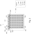
- Fig. 2 shows a front view of a device according to the Fig. 1A and/or the Fig. 1B .
- optical elements in the optical waveguide 400 are designed as discrete units. In other embodiments, they may also be designed continuously, as described above and below.
- Input coupling element 440 is optically coupled to a plurality of replication regions 500, with optical coupling 600 indicated by an arrow.
- Each element of the plurality of replication regions 500 is configured to receive a respective input light beam having an input beam profile and to provide a plurality of respective output light beams having respective output beam profiles.
- the light interacts with a replication region multiple times, for example after total reflection in the optical fiber.
- a first replication region 501 of the plurality of replication regions 500 is optically coupled 600 to the at least one coupling element 440, such that the first replication region 501 is configured to receive the light beam as the associated input light beam 300 of the first replication region.
- the first replication region 501 is further optically coupled 600 to a second replication region 502 of the plurality of replication regions 500, such that the second replication region 502 is configured to receive one of the plurality of associated output light beams 310 of the first replication region as the associated input light beam of the second replication region 305.
- the device 100 is configured to couple output light 610 from a set of the plurality of replication regions 500 out of the optical waveguide 400 to form the light distribution 200, as shown in the Fig. 1A and Fig. 1B shown.
- the light is emitted from an output region 630 of the optical waveguide 400.
- the plurality of replication regions 500 comprises a first group of replication regions 510 (highlighted by hatching), each of which is optically coupled to one another and transmits the light to individual group elements—with the exception of the last element of the first group—and distributes it further in a different direction to other replication regions that do not belong to the first group of replication regions.
- all replication regions belong either to the first group of replication regions or to the set of the plurality of replication regions. In other embodiments, however, this can be varied as desired.
- the light provided at the coupling element 440 can advantageously be converted into a lighting distribution.
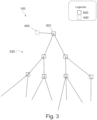
- Fig. 3 shows an example of a device with a tree structure.
- Fig. 3 shows a detailed view of a device 100, which is also arranged in an optical waveguide.
- a plurality of replication regions 500 are schematically shown, wherein a first replication region 501 is optically coupled to a coupling element 440.
- the further elements of the plurality of replication regions have a tree structure 530.
- the replication regions 500 can be configured both to transmit light within the optical waveguide and to couple light out of the optical waveguide to generate an illumination distribution.
- the tree structure further increases the degree of freedom of the illumination distribution that can be generated by a device 100.
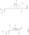
- Fig. 4 shows another embodiment of the Fig. 1A and the Fig. 1B .
- Fig. 4 shows an embodiment of a device 100, wherein the reference numerals are identical to the device of Fig. 1A and the Fig. 1B
- the device 100 of the Fig. 4 is configured to provide a lighting distribution 200 for illuminating an object 700.
- the light distribution 200 is arranged so that a plurality of beams 285 are emitted from different areas of the optical waveguide 400.
- the light distribution comprises different light beams, for example, beams 285, which overlap at the waveguide 400.
- a region of the waveguide 400 can thus be the starting point for light beams with different directions. This can be achieved, for example, by multiply exposed volume holograms used as replication regions and/or output coupling elements.
- the received light is effectively focused by the device 100 onto the object 700.
- the beams 285 are collimated and are emitted from the light guide 400 at discrete angular ranges.
- the optical waveguide 400 can comprise at least one outcoupling element.
- a respective outcoupling element can be provided for each of the plurality of beams 285.
- the respective outcoupling element can receive light from multiple replication regions.
- Fig. 5 shows a further device 100. This essentially corresponds to the device of Fig. 4 .
- the device of Fig. 5 is also arranged to position the object 700 at the same angles as the device 100 of the Fig. 4 to illuminate, but at a greater distance of the object 700 from the optical waveguide 400. Accordingly, the device 100 of the Fig. 5 larger than the device 100 of the Fig. 4 .
- Fig. 6 shows devices according to various embodiments that are multi-channel and/or switchable.
- Fig. 6(a) to Fig. 6(g) various examples of multi-channel or switchable devices designed to provide different light distributions.
- Various concepts for multi-channel waveguide systems are described below using devices 100 in (a) to (g). These concepts can utilize the high spectral and/or angular selectivity of diffractive elements, such as volume holograms or other microstructured optical elements, to transmit multiple beams independently of one another within the same volume of the light guide 400.
- High spectral selectivity is understood here to mean a drop in the efficiency of the element, for example, by 50% of the full width at half maximum (FWHM), for wavelength deviations from the design wavelength, for example, ⁇ 40 nm, for example ⁇ 10 nm.
- a drop in the efficiency of the element by 50% FWHM is expected when the beam angle of incidence deviates from a design angle for which the Each optical element is designed, for example, to receive an associated input light beam from this angle, for example, ⁇ 10°, for example, ⁇ 2°.
- multiple beams with different directions and/or wavelengths can propagate within the same volume of the optical waveguide 400 and can be selectively coupled and forwarded by associated, sometimes also described as "matching," optical elements.
- selectively acting replication regions can be provided within an identical volume of the optical waveguide 400. These can operate in superposition and convert the light into different luminous distributions for different characteristics, for example, angles of incidence.
- multiplexing for example, spectral multiplexing when the optical elements, for example, volume holograms, are configured to exhibit different coupling behaviors for different spectral properties of the light.
- Other types of multiplexing are also possible, such as angle-dependent or polarization-dependent multiplexing, as well as combinations thereof.
- the device in (a) shows a device 100 which is configured to receive light from a first light source 203 having a first wavelength ⁇ 1 and light of a second wavelength ⁇ 2 from a second light source 204, and to generate a luminous distribution 200 for each received wavelength.
- the luminous distribution 200 comprises a luminous distribution which results from the luminous distribution 200 of the Fig. 4 and a luminous distribution of fixation marks 230.
- Such a structure can have the advantage that it is possible to provide different luminous distributions with the same optical waveguide 400 in different wavelength ranges for different purposes, for example, in the example shown, the fixation marks 230 at a wavelength ⁇ 2 of the second light source 204 in the visible range and infrared light at a wavelength ⁇ 1 of the first light source 203 in the infrared range.
- Fig. 6(b) shows an alternative implementation of the device of Fig. 6(a) with a differently designed coupling element 440.
- the coupling element 440 comprises two different areas, wherein a first coupling area 440A is configured to couple the light of the first light source 203, and a second coupling region 440B is configured to couple the light of the second light source 203 into the optical waveguide 400.
- Fig. 6(c) to Fig. 6(g) show various possibilities for implementing switchable systems and/or systems that allow multiple light distributions to be superimposed, sometimes referred to as superposition.
- the light sources 203, 204 are arranged laterally offset and are coupled into the optical waveguide 400 by coupling elements 440A, 440B at different locations.
- the respective associated coupling elements 440A, 440B can be configured such that, even with similar light sources 203, 204, different couplings into the optical waveguide 400 are achieved, for example, different coupling angles.
- the device 100 can be configured to provide two illumination distributions, in the example shown, one illumination distribution per light source. In some examples, these illumination distributions can be selected independently of one another, for example, due to the previously described angle selectivity and/or wavelength selectivity of the optical elements used.
- Fig. 6(d) shows a variation of the Fig. 6(c) , wherein the two light sources 204, 203 strike a coupling element 440 at different angles. This is configured to couple the two light sources independently of each other into the optical waveguide 400.
- Fig. 6 (e) only one light source 203 is present. The angle of incidence of the light from the light source 203 is varied by a scanning mirror 460, resulting in a switchable illumination distribution.
- a switchable optical element 470 for example a switchable hologram, is present in the optical waveguide 400. This also allows a superposition of different illumination distributions to be achieved.
- the Fig. 6 (e) only one light source 203 is present.
- the angle of incidence of the light from the light source 203 is varied by a scanning mirror 460, resulting in a switchable illumination distribution.
- a switchable optical element 470 for example a switchable hologram, is present in the optical waveguide 400. This also allows a superposition of different illumination distributions
- a polarization-changing element 480 changes the polarization properties of the light from the light source 203.
- the optical elements of the device 100 can have polarization-dependent properties, so that different illumination distributions can also be brought about by varying the polarization of the incident light on the device 100.
- Fig. 6 (a) to Fig. 6 (g) The examples shown can also be combined with each other.
- different light sources with different polarization directions - as in the example of the Fig. 6(g) - with a scanning mirror - as in Fig. 6(e) shown - can be combined.
- any other combination of the elements and procedures shown is also possible.
- the Fig. 7A to Fig. 13B show devices used to provide a keratometer.
- the Fig. 14 and the Fig. 15 show different setups for a microscope.
- the Fig. 16 shows a calibration device for an optical device
- the Fig. 17 and the Fig. 18 show devices for area lighting and a window for a building.
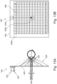
- Fig. 7A shows a side view of a keratometer according to the invention.
- Fig. 7B shows a frontal view.
- a device 100 provides a light distribution 200 for keratometric measurement of the cornea of an eye 800.
- the light reflected by the cornea of the eye 800 is detected by a detection device 900 along a detection beam path 905 and can then be analyzed to determine the topology of the cornea.
- the optical waveguide 400 of the device 100 has a recess 420.
- the light is provided by two light sources 203, 204 and coupled in by two coupling elements 440, 441. Starting from the respective coupling elements 440, 441, the light is replicated over a plurality of replication areas and coupled out in the direction of the eye 800 as illumination distribution 200.
- the surface normal of the optical waveguide is arranged parallel to a main visual axis of the eye 800.
- the normal of the optical waveguide may also be arranged not parallel to the main visual axis of the eye 800. This can, for example, reduce or avoid reflections.
- Fig. 8 shows another example of a keratometer.
- the plurality of replication areas 500 are coupled to one another in such a way that an illumination distribution such as the illumination distribution 200 of the Fig. 7(a) can be provided by the plurality of replication areas 500.
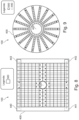
- the Fig. 9 to Fig. 12 show different implementations for keratometry devices.
- the devices of the Fig. 9 to Fig. 11 each have a recess 420 in the center of a round optical waveguide 400.
- the light is received near the recess 420 by a plurality of coupling elements 440 and forwarded in series to a plurality of replication regions, which also serve to couple the light out in the direction of the eye 800.
- Fig. 10 shows a similar arrangement, wherein the plurality of coupling elements 440 is not arranged in spatial proximity to the recess 420, but near the edge of the optical waveguide 400.
- the light received by the plurality of coupling elements 440 is forwarded in series to the plurality of replication regions.
- the replication regions can be of any shape. In the example shown, the Fig. 10 These are rectangular in shape, but near the recess 420 they have a more complex shape, although other shapes are also possible and the shapes shown are only examples.
- the coupling elements 440 are again arranged according to the Fig. 9 arranged near the recess 420.
- the optical coupling of the plurality of replication regions now has a tree structure 530. This allows for homogeneous illumination of the eye.
- the light is coupled in via a single coupling element 440 in the center of the optical waveguide 400.
- the plurality of replication regions 500 is in the embodiment of the Fig. 12 circular in shape and overlap each other in the frontal view. This can be achieved by an offset within the optical waveguide or by a volumetric overlap, for example, in volume holograms, as described above. Due to the angular selectivity of some diffractive elements, it may be possible to provide a well-defined light distribution 200 despite the overlap of the plurality of output coupling regions 500.
- Fig. 13A and Fig. 13B show an alternative implementation for a keratometer with fixation marks.
- the optical waveguide 400 has no recess.
- the observation by the detection device 900 takes place through the optical waveguide 400.
- the keratometer 120 can be a device 100 according to an embodiment of the Fig. 6 Shown here is an embodiment according to the Fig. 6(b) As in connection with the Fig. 6 (b) As described, the two light sources 203, 204 generate two illumination distributions 200, wherein the first light source 203 provides the illumination distribution 200 required for keratometry in the infrared, and a light source 204 emitting in the visible provides fixation marks 230. In the side view of the Fig.
- the device 100 has a coupling element 440a for the infrared light, which according to the embodiment of the Fig. 2
- the light from the light source 204 is coupled in by a coupling element 440b and coupled out by a replication region 500b to provide the fixation marks 230 as an illumination distribution.
- the Fig. 14 and the Fig. 15 show a microscope according to various embodiments.
- the microscope 130 has a sample illumination device 140 and an eyepiece 142.
- This comprises a device 100 according to the previous embodiments and is configured to generate an illumination distribution on a sample 700.
- the illumination distribution can in particular be a pattern on the sample 700.
- the device 100 can be configured to receive light from a multiply modulatable light source 205. The received light can then be converted into a light distribution 200.
- the multiply modulatable light source can be arranged both on the side facing away from the microscope, as in Fig. 14 shown, but it can also be arranged on the side facing the microscope, as in Fig. 15 shown. Due to the design freedom of the device 100, in particular, angle-variable illumination of the microscopic sample 700 can be provided. This allows illumination requirements in microscopy, such as those encountered in Fourier ptychography, to be met with reduced effort and/or increased quality.
- the modulatable light sources can be switched in a time-selective manner.
- a light distribution can be provided by a light source arrangement, as described above and below.
- Fig. 16 shows a calibration device 150 for an optical device 910 according to various embodiments.
- the device according to various embodiments can advantageously be used for calibrating and adjusting imaging optical systems, for example, lenses. This can be particularly advantageous in connection with difficult-to-access optical devices, such as lenses or other imaging systems located inside machines or used under difficult environmental conditions, for example, underwater or in space.
- difficult-to-access optical devices such as lenses or other imaging systems located inside machines or used under difficult environmental conditions, for example, underwater or in space.
- a planar optical waveguide system 400 is arranged directly in the beam path 290 of an optical device 910.
- the device 100 is configured to receive light from a multiply modulatable light source 205 and to provide an illumination distribution.
- the multiply modulatable light source 205 can also be a non-modulatable light source, for example, if only a single illumination distribution is required, for example, a single test image.
- This light distribution 200 can now be used to calibrate the optical device 910.
- different wavelengths of light can be provided by the multiply modulatable light source 205 simultaneously or sequentially.
- the light distribution 200 can be provided such that the light 210 leaves the optical waveguide in such a way that it is under well-defined angles of incidence into the optical device 910. This allows calibration of the optical device 910 to be advantageously carried out.
- the calibration device 150 is located in a first installation position 930.
- Such an installation position outside the optical elements of the optical device 910 can in particular enable a simple replaceable installation, for example as a filter element.
- the calibration device 150 can be installed at a position within optical elements of the optical device 940. This can efficiently enable partial calibration of individual optical elements.
- the luminous distribution can, for example, represent a nominal wavefront of the optical device, which would be created by the upstream lens subgroups and a standard test object.
- the installation of calibration devices such as the calibration device 150 shown can be permanent or temporary.
- the calibration device can be retracted into the beam path for calibration. In other embodiments, it can also remain permanently in the beam path. It can be advantageous here that, due to the strong wavelength and/or angular selectivity of the devices used, the influence of the calibration device on the beam path of the optical device can be minimal.
- the device can be taken into account in the optical design of the optical device. Due to the high angular and spectral selectivity of the device in the optical waveguide, only narrow spectral subbands can be filtered out by an optical waveguide for a selected field point of the optical device, so that the functioning of the optical device is not affected or is only minimally affected. At these wavelength bands, the alignment marks and test patterns can be reflected with high efficiency.
- test patterns offered by the device can be displayed at different distances, wavelengths, positions, and shapes. It is possible to generate multiple test patterns simultaneously using one radiation source. However, multiple light source arrangements can also be used and/or other of the described procedures can be applied to generate additional or alternatively switchable patterns.
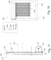
- Fig. 17 shows a surface light 170 comprising a device 100 according to various embodiments.
- Light from a first light source 203 is provided by a parabolic reflector 218 to a coupling element 450 of the device 100.
- the coupled light is forwarded by means of a plurality of replication regions within the optical waveguide 400.
- the light distribution 200 is provided by a coupling-out element 620.
- other possibilities for providing the light distribution 200 as described above, can also be used.
- very small dimensions A of the optical waveguide 400 can be realized, while at the same time a high degree of freedom of the light distribution 200 is available.
- Collimated light is provided as luminous distribution 200, but other, more complex luminous distributions can also be generated.
- Fig. 18 shows a window 180.
- the window 180 comprises a window glass 430, with an optical waveguide 400 according to various embodiments of the device described above.
- the window 180 further comprises a window frame 190.
- a light source 203 is arranged in a manner that is invisible.
- the light source 203 is configured to provide infrared light and to provide it to the at least one coupling element 450 of the device 100.
- the device 100 in the optical waveguide generates an illumination distribution 200.
- the illumination distribution 200 can be provided as a heat source, for example, as a heater for a room in a house, on at least one side of the window.
- the infrared light provided by the light source 203 can have an intensity maximum, in particular, in a spectral range of 1 to 10 ⁇ m.
- Fig. 19 shows a lighting device for an active eye implant according to an embodiment.
- the device 100 is configured to provide light from a light source 203 to an active ocular implant in the eye 800 of a user.
- the light is coupled into the optical waveguide 400 by a coupling element 440.
- the optical waveguide 400 is arranged obliquely relative to the eye. This can offer aesthetic advantages when the optical waveguide is arranged in eyeglasses.
- the light propagates in the optical waveguide 440 in total internal reflection and is coupled out by an outcoupling element 620, providing the light distribution 200 to the eye and thus to the ocular implant.
- the light is provided as a plurality of collimated beams, for example, a collimated beam bundle 212.
- the plurality of collimated beams are effectively focused because, emanating from the optical waveguide 400, they pass through a larger exit area on the optical waveguide than in an imaginary focusing plane (indicated as a dot-dashed line in front of the eye 800).
- the plurality of coupled out beams ensures that the ocular implant is supplied with light, regardless of the viewing direction, even when the eye rotates around the eye pivot point 800a.
Landscapes
- Physics & Mathematics (AREA)
- General Physics & Mathematics (AREA)
- Optics & Photonics (AREA)
- Health & Medical Sciences (AREA)
- Life Sciences & Earth Sciences (AREA)
- General Health & Medical Sciences (AREA)
- Surgery (AREA)
- Chemical & Material Sciences (AREA)
- Analytical Chemistry (AREA)
- Medical Informatics (AREA)
- Veterinary Medicine (AREA)
- Engineering & Computer Science (AREA)
- Biomedical Technology (AREA)
- Heart & Thoracic Surgery (AREA)
- Biophysics (AREA)
- Molecular Biology (AREA)
- Animal Behavior & Ethology (AREA)
- Public Health (AREA)
- Ophthalmology & Optometry (AREA)
- Microscoopes, Condenser (AREA)
- Investigating Or Analysing Materials By Optical Means (AREA)
- Optical Couplings Of Light Guides (AREA)
- Light Guides In General And Applications Therefor (AREA)
- Optical Integrated Circuits (AREA)
- Optical Filters (AREA)
- Holo Graphy (AREA)
- Planar Illumination Modules (AREA)
- Eye Examination Apparatus (AREA)
- Diffracting Gratings Or Hologram Optical Elements (AREA)
Applications Claiming Priority (2)
| Application Number | Priority Date | Filing Date | Title |
|---|---|---|---|
| DE102019108677.9A DE102019108677A1 (de) | 2019-04-03 | 2019-04-03 | Vorrichtungen zum Erzeugen von Leuchtverteilungen mit Lichtwellenleitern |
| PCT/EP2020/059118 WO2020201281A1 (de) | 2019-04-03 | 2020-03-31 | Vorrichtungen zum erzeugen von leuchtverteilungen mit lichtwellenleitern |
Publications (2)
| Publication Number | Publication Date |
|---|---|
| EP3946000A1 EP3946000A1 (de) | 2022-02-09 |
| EP3946000B1 true EP3946000B1 (de) | 2025-03-19 |
Family
ID=70154405
Family Applications (1)
| Application Number | Title | Priority Date | Filing Date |
|---|---|---|---|
| EP20716444.3A Active EP3946000B1 (de) | 2019-04-03 | 2020-03-31 | Vorrichtungen zum erzeugen von leuchtverteilungen mit lichtwellenleitern |
Country Status (6)
| Country | Link |
|---|---|
| US (1) | US20220206208A1 (https=) |
| EP (1) | EP3946000B1 (https=) |
| JP (1) | JP2022530185A (https=) |
| CN (1) | CN113660897A (https=) |
| DE (1) | DE102019108677A1 (https=) |
| WO (1) | WO2020201281A1 (https=) |
Families Citing this family (4)
| Publication number | Priority date | Publication date | Assignee | Title |
|---|---|---|---|---|
| DE102019108679A1 (de) | 2019-04-03 | 2020-10-08 | Carl Zeiss Ag | Vorrichtungen zur Energieversorgung eines aktiven Augenimplantats |
| DE102019108678A1 (de) | 2019-04-03 | 2020-10-08 | Carl Zeiss Ag | Vorrichtung zur Energieversorgung eines aktiven Augenimplantats |
| DE102022102646A1 (de) | 2022-02-04 | 2023-08-10 | Carl Zeiss Jena Gmbh | Replikationsprozess eines master holographisch optischen elements mit variabler beleuchtung |
| US20240036325A1 (en) * | 2022-07-27 | 2024-02-01 | Apple Inc. | Optical Systems with Sequential Illumination |
Citations (5)
| Publication number | Priority date | Publication date | Assignee | Title |
|---|---|---|---|---|
| US7252425B2 (en) * | 2004-06-23 | 2007-08-07 | Samsung Electronics Co., Ltd. | Light guide panel usable with backlight unit, backlight unit employing the same, and manufacturing method thereof |
| US20170052384A1 (en) * | 2014-04-30 | 2017-02-23 | Hewlett-Packard Development Company, L.P. | Imaging appratus and methods using diffraction-based illumination |
| US10345593B2 (en) * | 2015-03-16 | 2019-07-09 | Magic Leap, Inc. | Methods and systems for providing augmented reality content for treating color blindness |
| US10613266B2 (en) * | 2017-06-16 | 2020-04-07 | Samsung Display Co., Ltd. | Backlight unit and display device including the same |
| US20200150042A1 (en) * | 2017-05-04 | 2020-05-14 | The Regents Of The University Of California | Waveguide-based side-illumination technique for muse microscopy and associated histology cassettes |
Family Cites Families (35)
| Publication number | Priority date | Publication date | Assignee | Title |
|---|---|---|---|---|
| CA2442161A1 (en) * | 2000-12-21 | 2002-06-27 | Waqidi Falicoff | Light conduit with radial light ejecting structure |
| US6760512B2 (en) * | 2001-06-08 | 2004-07-06 | Hrl Laboratories, Llc | Electro-optical programmable true-time delay generator |
| US6810167B2 (en) * | 2001-10-29 | 2004-10-26 | Fujitsu Limited | Wavelength division demultiplexing apparatus |
| US7206107B2 (en) * | 2004-12-13 | 2007-04-17 | Nokia Corporation | Method and system for beam expansion in a display device |
| JP4655771B2 (ja) * | 2005-06-17 | 2011-03-23 | ソニー株式会社 | 光学装置及び虚像表示装置 |
| US8466953B2 (en) * | 2006-06-02 | 2013-06-18 | Nokia Corporation | Stereoscopic exit pupil expander display |
| EP3667399A1 (en) * | 2007-06-04 | 2020-06-17 | Magic Leap, Inc. | A diffractive beam expander |
| US7729572B1 (en) * | 2008-07-08 | 2010-06-01 | Hrl Laboratories, Llc | Optical tapped time delay modules and arrays |
| US8200055B2 (en) * | 2010-07-19 | 2012-06-12 | Harish Subbaraman | Two-dimensional surface normal slow-light photonic crystal waveguide optical phased array |
| DE102011102355B4 (de) | 2011-05-24 | 2025-11-27 | Carl Zeiss Meditec Ag | System zur Bestimmung der Topographie der Kornea eines Auges |
| KR20140112059A (ko) * | 2012-01-11 | 2014-09-22 | 시리얼 테크놀로지즈 에스.에이. | 화소 매트릭스 및/또는 디스플레이용 제어가능한 공간 광 변조기를 조명하기 위한 광학 장치 |
| DE102012211846A1 (de) * | 2012-07-06 | 2013-08-01 | Carl Zeiss Smt Gmbh | Verfahren zum Messen einer winkelaufgelösten Intensitätsverteilung sowie Projektionsbelichtungsanlage |
| US8957374B2 (en) * | 2012-09-28 | 2015-02-17 | Corning Incorporated | Systems and methods for measuring birefringence in glass and glass-ceramics |
| DE102013219625B3 (de) * | 2013-09-27 | 2015-01-22 | Carl Zeiss Ag | Brillenglas für eine auf den Kopf eines Benutzers aufsetzbare und ein Bild erzeugende Anzeigevorrichtung sowie Anzeigevorrichtung mit einem solchen Brillenglas |
| KR102202454B1 (ko) * | 2013-11-29 | 2021-01-14 | 엘지디스플레이 주식회사 | 박막형 시야 범위 조절 백 라이트 유닛 및 이를 이용한 박막 평판형 시야 범위 조절 표시장치 |
| DE102014101219A1 (de) | 2014-01-31 | 2015-08-06 | Carl Zeiss Ag | Beleuchtungseinrichtung zur Fourier-Ptychographie |
| US9939628B2 (en) * | 2014-03-20 | 2018-04-10 | CSEM Centre Suisse d'Electronique et de Microtechnique SA—Recherche et Développement | Imaging system |
| WO2015151255A1 (ja) * | 2014-04-03 | 2015-10-08 | 日立マクセル株式会社 | 導光板及び導光板を用いた装置 |
| KR20220054722A (ko) * | 2014-05-16 | 2022-05-03 | 코닝 인코포레이티드 | 액정 디스플레이 장치용 엣지 조명형 백라이트 유닛 |
| DE102014112242A1 (de) | 2014-08-26 | 2016-03-03 | Carl Zeiss Ag | Phasenkontrast-Bildgebung |
| US9335556B2 (en) * | 2014-09-04 | 2016-05-10 | Microsoft Technology Licensing, Llc | Variable focal backlighting |
| EP3198192A1 (en) * | 2014-09-26 | 2017-08-02 | Milan Momcilo Popovich | Holographic waveguide opticaltracker |
| US20160231567A1 (en) * | 2015-02-09 | 2016-08-11 | Pasi Saarikko | Display System |
| US9513480B2 (en) * | 2015-02-09 | 2016-12-06 | Microsoft Technology Licensing, Llc | Waveguide |
| CN105281003B (zh) * | 2015-08-04 | 2018-05-04 | 电子科技大学 | 基于圆极化模的径向波导功率分配器 |
| US9989763B2 (en) * | 2015-12-04 | 2018-06-05 | Microsoft Technology Licensing, Llc | Imaging using multiple different narrow bands of light having respective different emission peaks |
| US10915066B2 (en) * | 2015-12-22 | 2021-02-09 | Covestro Deutschland Ag | Device and method for the industrial production of volume reflection holograms with substrate-guided reconstruction beams |
| JP2017156389A (ja) * | 2016-02-29 | 2017-09-07 | セイコーエプソン株式会社 | 光学素子、照明装置、画像表示装置及びプロジェクター |
| DE102016116309A1 (de) | 2016-05-02 | 2017-11-02 | Carl Zeiss Microscopy Gmbh | Beleuchtungsmodul für winkelselektive Beleuchtung |
| WO2018039273A1 (en) * | 2016-08-22 | 2018-03-01 | Magic Leap, Inc. | Dithering methods and apparatus for wearable display device |
| DE102016115938A1 (de) * | 2016-08-26 | 2018-03-01 | Carl Zeiss Jena Gmbh | Wellenleiter sowie Vorrichtungen zur Dateneinspiegelung |
| KR102324728B1 (ko) * | 2016-09-07 | 2021-11-10 | 매직 립, 인코포레이티드 | 두꺼운 미디어를 포함하는 가상 현실, 증강 현실 및 혼합 현실 시스템들 및 관련된 방법들 |
| US10859833B2 (en) * | 2017-08-18 | 2020-12-08 | Tipd, Llc | Waveguide image combiner for augmented reality displays |
| DE102017130344A1 (de) * | 2017-12-18 | 2019-06-19 | Carl Zeiss Ag | Optisches System zum Übertragen eines Quellbildes |
| US10983338B2 (en) * | 2017-12-29 | 2021-04-20 | Palo Alto Research Center Incorporated | Exit-pupil expander used distribute light over a liquid-crystal variable retarder |
-
2019
- 2019-04-03 DE DE102019108677.9A patent/DE102019108677A1/de active Pending
-
2020
- 2020-03-31 JP JP2021558920A patent/JP2022530185A/ja active Pending
- 2020-03-31 US US17/600,857 patent/US20220206208A1/en active Pending
- 2020-03-31 CN CN202080026972.1A patent/CN113660897A/zh active Pending
- 2020-03-31 EP EP20716444.3A patent/EP3946000B1/de active Active
- 2020-03-31 WO PCT/EP2020/059118 patent/WO2020201281A1/de not_active Ceased
Patent Citations (5)
| Publication number | Priority date | Publication date | Assignee | Title |
|---|---|---|---|---|
| US7252425B2 (en) * | 2004-06-23 | 2007-08-07 | Samsung Electronics Co., Ltd. | Light guide panel usable with backlight unit, backlight unit employing the same, and manufacturing method thereof |
| US20170052384A1 (en) * | 2014-04-30 | 2017-02-23 | Hewlett-Packard Development Company, L.P. | Imaging appratus and methods using diffraction-based illumination |
| US10345593B2 (en) * | 2015-03-16 | 2019-07-09 | Magic Leap, Inc. | Methods and systems for providing augmented reality content for treating color blindness |
| US20200150042A1 (en) * | 2017-05-04 | 2020-05-14 | The Regents Of The University Of California | Waveguide-based side-illumination technique for muse microscopy and associated histology cassettes |
| US10613266B2 (en) * | 2017-06-16 | 2020-04-07 | Samsung Display Co., Ltd. | Backlight unit and display device including the same |
Also Published As
| Publication number | Publication date |
|---|---|
| WO2020201281A1 (de) | 2020-10-08 |
| US20220206208A1 (en) | 2022-06-30 |
| DE102019108677A1 (de) | 2020-10-08 |
| CN113660897A (zh) | 2021-11-16 |
| EP3946000A1 (de) | 2022-02-09 |
| JP2022530185A (ja) | 2022-06-28 |
Similar Documents
| Publication | Publication Date | Title |
|---|---|---|
| EP3946000B1 (de) | Vorrichtungen zum erzeugen von leuchtverteilungen mit lichtwellenleitern | |
| DE102009037841B4 (de) | Optisches System mit Wellenfrontanalysesystem und Baugruppe mit Wellenfrontanalysesystem für ein Mikroskop mit Mikroskopchassis | |
| DE102015203443B4 (de) | Ophthalmologische Bildgebungsvorrichtung und optische Einheit, die an dieser befestigbar ist | |
| DE102008047400B9 (de) | Augenchirurgie-Messsystem | |
| EP1494575B1 (de) | Messung optischer eigenschaften | |
| DE102016203487B4 (de) | Augenmikroskopsystem | |
| DE102016001659B4 (de) | Augenoperationsmikroskop und Augenoperationszusatzgerät | |
| EP1918753B1 (de) | Operationsmikroskop mit OCT-System | |
| EP2564763B1 (de) | Ophthalmologisches Analysegerät und Verfahren | |
| EP3607392B1 (de) | Vorrichtung zur energieversorgung von und/oder kommunikation mit einem augenimplantat mittels beleuchtungsstrahlung | |
| DE102016203473B4 (de) | Augenmikroskop | |
| WO2016041640A1 (de) | System zur optischen kohärenztomographie, umfassend ein zoombares kepler-system | |
| EP3419719B1 (de) | Vorrichtung und verfahren zur versorgung eines aktiven augenimplantats | |
| DE102011088038B4 (de) | Operationsmikroskopsystem für die Ophthalmologie und zugehörige Detektionseinheit | |
| WO2002053020A2 (de) | Vorrichtung und verfahren zur bildgebung, stimulierung, messung und therapie insbesondere am auge | |
| WO2013189591A1 (de) | Augenchirurgie-mikroskop mit einrichtung zur ametropie-messung | |
| EP1596709B1 (de) | Anordnung zur bildfeldverbesserung bei ophthalmologischen geräten | |
| WO2012159752A2 (de) | Mikroskopiesystem zur augenuntersuchung und verfahren zum betreiben eines mikroskopiesystems | |
| EP2988710B1 (de) | Okuläre therapievorrichtung | |
| WO2009143976A1 (de) | Optisches system für ophthalmologische geräte, insbesondere funduskameras | |
| AT507140B1 (de) | Mehrfach-a-scan kurzkohärenz-interferometrische distanzmessung am auge | |
| EP3949080B1 (de) | Vorrichtung zur energieversorgung eines aktiven augenimplantats | |
| WO2020201426A1 (de) | Vorrichtungen zur energieversorgung eines aktiven augenimplantats | |
| DE102017129951B3 (de) | Vorrichtung zur ophthalmologischen Blickfixierung für Patienten mit beliebiger Sehschärfe | |
| DE202006020039U1 (de) | Variable Blende, Beleuchtungseinrichtung sowie optisches Beobachtungsgerät |
Legal Events
| Date | Code | Title | Description |
|---|---|---|---|
| STAA | Information on the status of an ep patent application or granted ep patent |
Free format text: STATUS: UNKNOWN |
|
| STAA | Information on the status of an ep patent application or granted ep patent |
Free format text: STATUS: THE INTERNATIONAL PUBLICATION HAS BEEN MADE |
|
| PUAI | Public reference made under article 153(3) epc to a published international application that has entered the european phase |
Free format text: ORIGINAL CODE: 0009012 |
|
| STAA | Information on the status of an ep patent application or granted ep patent |
Free format text: STATUS: REQUEST FOR EXAMINATION WAS MADE |
|
| 17P | Request for examination filed |
Effective date: 20211028 |
|
| AK | Designated contracting states |
Kind code of ref document: A1 Designated state(s): AL AT BE BG CH CY CZ DE DK EE ES FI FR GB GR HR HU IE IS IT LI LT LU LV MC MK MT NL NO PL PT RO RS SE SI SK SM TR |
|
| DAV | Request for validation of the european patent (deleted) | ||
| DAX | Request for extension of the european patent (deleted) | ||
| STAA | Information on the status of an ep patent application or granted ep patent |
Free format text: STATUS: EXAMINATION IS IN PROGRESS |
|
| 17Q | First examination report despatched |
Effective date: 20230612 |
|
| GRAP | Despatch of communication of intention to grant a patent |
Free format text: ORIGINAL CODE: EPIDOSNIGR1 |
|
| STAA | Information on the status of an ep patent application or granted ep patent |
Free format text: STATUS: GRANT OF PATENT IS INTENDED |
|
| INTG | Intention to grant announced |
Effective date: 20241029 |
|
| GRAS | Grant fee paid |
Free format text: ORIGINAL CODE: EPIDOSNIGR3 |
|
| GRAA | (expected) grant |
Free format text: ORIGINAL CODE: 0009210 |
|
| STAA | Information on the status of an ep patent application or granted ep patent |
Free format text: STATUS: THE PATENT HAS BEEN GRANTED |
|
| AK | Designated contracting states |
Kind code of ref document: B1 Designated state(s): AL AT BE BG CH CY CZ DE DK EE ES FI FR GB GR HR HU IE IS IT LI LT LU LV MC MK MT NL NO PL PT RO RS SE SI SK SM TR |
|
| REG | Reference to a national code |
Ref country code: GB Ref legal event code: FG4D Free format text: NOT ENGLISH |
|
| REG | Reference to a national code |
Ref country code: CH Ref legal event code: EP |
|
| REG | Reference to a national code |
Ref country code: DE Ref legal event code: R096 Ref document number: 502020010638 Country of ref document: DE |
|
| REG | Reference to a national code |
Ref country code: IE Ref legal event code: FG4D Free format text: LANGUAGE OF EP DOCUMENT: GERMAN |
|
| PG25 | Lapsed in a contracting state [announced via postgrant information from national office to epo] |
Ref country code: RS Free format text: LAPSE BECAUSE OF FAILURE TO SUBMIT A TRANSLATION OF THE DESCRIPTION OR TO PAY THE FEE WITHIN THE PRESCRIBED TIME-LIMIT Effective date: 20250619 |
|
| PG25 | Lapsed in a contracting state [announced via postgrant information from national office to epo] |
Ref country code: FI Free format text: LAPSE BECAUSE OF FAILURE TO SUBMIT A TRANSLATION OF THE DESCRIPTION OR TO PAY THE FEE WITHIN THE PRESCRIBED TIME-LIMIT Effective date: 20250319 |
|
| REG | Reference to a national code |
Ref country code: LT Ref legal event code: MG9D |
|
| PG25 | Lapsed in a contracting state [announced via postgrant information from national office to epo] |
Ref country code: NO Free format text: LAPSE BECAUSE OF FAILURE TO SUBMIT A TRANSLATION OF THE DESCRIPTION OR TO PAY THE FEE WITHIN THE PRESCRIBED TIME-LIMIT Effective date: 20250619 |
|
| PG25 | Lapsed in a contracting state [announced via postgrant information from national office to epo] |
Ref country code: HR Free format text: LAPSE BECAUSE OF FAILURE TO SUBMIT A TRANSLATION OF THE DESCRIPTION OR TO PAY THE FEE WITHIN THE PRESCRIBED TIME-LIMIT Effective date: 20250319 |
|
| PG25 | Lapsed in a contracting state [announced via postgrant information from national office to epo] |
Ref country code: LV Free format text: LAPSE BECAUSE OF FAILURE TO SUBMIT A TRANSLATION OF THE DESCRIPTION OR TO PAY THE FEE WITHIN THE PRESCRIBED TIME-LIMIT Effective date: 20250319 |
|
| PG25 | Lapsed in a contracting state [announced via postgrant information from national office to epo] |
Ref country code: GR Free format text: LAPSE BECAUSE OF FAILURE TO SUBMIT A TRANSLATION OF THE DESCRIPTION OR TO PAY THE FEE WITHIN THE PRESCRIBED TIME-LIMIT Effective date: 20250620 Ref country code: BG Free format text: LAPSE BECAUSE OF FAILURE TO SUBMIT A TRANSLATION OF THE DESCRIPTION OR TO PAY THE FEE WITHIN THE PRESCRIBED TIME-LIMIT Effective date: 20250319 |
|
| REG | Reference to a national code |
Ref country code: NL Ref legal event code: MP Effective date: 20250319 |
|
| PG25 | Lapsed in a contracting state [announced via postgrant information from national office to epo] |
Ref country code: NL Free format text: LAPSE BECAUSE OF FAILURE TO SUBMIT A TRANSLATION OF THE DESCRIPTION OR TO PAY THE FEE WITHIN THE PRESCRIBED TIME-LIMIT Effective date: 20250319 |
|
| PG25 | Lapsed in a contracting state [announced via postgrant information from national office to epo] |
Ref country code: SE Free format text: LAPSE BECAUSE OF FAILURE TO SUBMIT A TRANSLATION OF THE DESCRIPTION OR TO PAY THE FEE WITHIN THE PRESCRIBED TIME-LIMIT Effective date: 20250319 |
|
| PG25 | Lapsed in a contracting state [announced via postgrant information from national office to epo] |
Ref country code: SM Free format text: LAPSE BECAUSE OF FAILURE TO SUBMIT A TRANSLATION OF THE DESCRIPTION OR TO PAY THE FEE WITHIN THE PRESCRIBED TIME-LIMIT Effective date: 20250319 |
|
| PG25 | Lapsed in a contracting state [announced via postgrant information from national office to epo] |
Ref country code: ES Free format text: LAPSE BECAUSE OF FAILURE TO SUBMIT A TRANSLATION OF THE DESCRIPTION OR TO PAY THE FEE WITHIN THE PRESCRIBED TIME-LIMIT Effective date: 20250319 Ref country code: PT Free format text: LAPSE BECAUSE OF FAILURE TO SUBMIT A TRANSLATION OF THE DESCRIPTION OR TO PAY THE FEE WITHIN THE PRESCRIBED TIME-LIMIT Effective date: 20250721 |
|
| PG25 | Lapsed in a contracting state [announced via postgrant information from national office to epo] |
Ref country code: IT Free format text: LAPSE BECAUSE OF FAILURE TO SUBMIT A TRANSLATION OF THE DESCRIPTION OR TO PAY THE FEE WITHIN THE PRESCRIBED TIME-LIMIT Effective date: 20250319 Ref country code: PL Free format text: LAPSE BECAUSE OF FAILURE TO SUBMIT A TRANSLATION OF THE DESCRIPTION OR TO PAY THE FEE WITHIN THE PRESCRIBED TIME-LIMIT Effective date: 20250319 |
|
| PG25 | Lapsed in a contracting state [announced via postgrant information from national office to epo] |
Ref country code: EE Free format text: LAPSE BECAUSE OF FAILURE TO SUBMIT A TRANSLATION OF THE DESCRIPTION OR TO PAY THE FEE WITHIN THE PRESCRIBED TIME-LIMIT Effective date: 20250319 Ref country code: CZ Free format text: LAPSE BECAUSE OF FAILURE TO SUBMIT A TRANSLATION OF THE DESCRIPTION OR TO PAY THE FEE WITHIN THE PRESCRIBED TIME-LIMIT Effective date: 20250319 |
|
| PG25 | Lapsed in a contracting state [announced via postgrant information from national office to epo] |
Ref country code: RO Free format text: LAPSE BECAUSE OF FAILURE TO SUBMIT A TRANSLATION OF THE DESCRIPTION OR TO PAY THE FEE WITHIN THE PRESCRIBED TIME-LIMIT Effective date: 20250319 |
|
| REG | Reference to a national code |
Ref country code: CH Ref legal event code: H13 Free format text: ST27 STATUS EVENT CODE: U-0-0-H10-H13 (AS PROVIDED BY THE NATIONAL OFFICE) Effective date: 20251024 |
|
| PG25 | Lapsed in a contracting state [announced via postgrant information from national office to epo] |
Ref country code: SK Free format text: LAPSE BECAUSE OF FAILURE TO SUBMIT A TRANSLATION OF THE DESCRIPTION OR TO PAY THE FEE WITHIN THE PRESCRIBED TIME-LIMIT Effective date: 20250319 |
|
| PG25 | Lapsed in a contracting state [announced via postgrant information from national office to epo] |
Ref country code: IS Free format text: LAPSE BECAUSE OF FAILURE TO SUBMIT A TRANSLATION OF THE DESCRIPTION OR TO PAY THE FEE WITHIN THE PRESCRIBED TIME-LIMIT Effective date: 20250719 |
|
| PG25 | Lapsed in a contracting state [announced via postgrant information from national office to epo] |
Ref country code: LU Free format text: LAPSE BECAUSE OF NON-PAYMENT OF DUE FEES Effective date: 20250331 |
|
| REG | Reference to a national code |
Ref country code: BE Ref legal event code: MM Effective date: 20250331 |
|
| PG25 | Lapsed in a contracting state [announced via postgrant information from national office to epo] |
Ref country code: MC Free format text: LAPSE BECAUSE OF FAILURE TO SUBMIT A TRANSLATION OF THE DESCRIPTION OR TO PAY THE FEE WITHIN THE PRESCRIBED TIME-LIMIT Effective date: 20250319 |
|
| REG | Reference to a national code |
Ref country code: DE Ref legal event code: R097 Ref document number: 502020010638 Country of ref document: DE |
|
| PG25 | Lapsed in a contracting state [announced via postgrant information from national office to epo] |
Ref country code: DK Free format text: LAPSE BECAUSE OF FAILURE TO SUBMIT A TRANSLATION OF THE DESCRIPTION OR TO PAY THE FEE WITHIN THE PRESCRIBED TIME-LIMIT Effective date: 20250319 |
|
| PG25 | Lapsed in a contracting state [announced via postgrant information from national office to epo] |
Ref country code: BE Free format text: LAPSE BECAUSE OF NON-PAYMENT OF DUE FEES Effective date: 20250331 |
|
| PG25 | Lapsed in a contracting state [announced via postgrant information from national office to epo] |
Ref country code: CH Free format text: LAPSE BECAUSE OF NON-PAYMENT OF DUE FEES Effective date: 20250331 |
|
| PG25 | Lapsed in a contracting state [announced via postgrant information from national office to epo] |
Ref country code: IE Free format text: LAPSE BECAUSE OF NON-PAYMENT OF DUE FEES Effective date: 20250331 |
|
| PLBE | No opposition filed within time limit |
Free format text: ORIGINAL CODE: 0009261 |
|
| STAA | Information on the status of an ep patent application or granted ep patent |
Free format text: STATUS: NO OPPOSITION FILED WITHIN TIME LIMIT |
|
| REG | Reference to a national code |
Ref country code: CH Ref legal event code: L10 Free format text: ST27 STATUS EVENT CODE: U-0-0-L10-L00 (AS PROVIDED BY THE NATIONAL OFFICE) Effective date: 20260128 |
|
| 26N | No opposition filed |
Effective date: 20251222 |
|
| PGFP | Annual fee paid to national office [announced via postgrant information from national office to epo] |
Ref country code: GB Payment date: 20260324 Year of fee payment: 7 |
|
| PGFP | Annual fee paid to national office [announced via postgrant information from national office to epo] |
Ref country code: DE Payment date: 20260319 Year of fee payment: 7 |
|
| PGFP | Annual fee paid to national office [announced via postgrant information from national office to epo] |
Ref country code: FR Payment date: 20260323 Year of fee payment: 7 |