EP3945084B1 - Composting system for organic waste - Google Patents
Composting system for organic waste Download PDFInfo
- Publication number
- EP3945084B1 EP3945084B1 EP21184209.1A EP21184209A EP3945084B1 EP 3945084 B1 EP3945084 B1 EP 3945084B1 EP 21184209 A EP21184209 A EP 21184209A EP 3945084 B1 EP3945084 B1 EP 3945084B1
- Authority
- EP
- European Patent Office
- Prior art keywords
- composting
- compartment
- compost
- composting compartment
- frame
- Prior art date
- Legal status (The legal status is an assumption and is not a legal conclusion. Google has not performed a legal analysis and makes no representation as to the accuracy of the status listed.)
- Active
Links
- 238000009264 composting Methods 0.000 title claims description 339
- 239000010815 organic waste Substances 0.000 title claims description 34
- 239000002361 compost Substances 0.000 claims description 115
- 230000035800 maturation Effects 0.000 claims description 30
- 238000000034 method Methods 0.000 claims description 14
- 235000011389 fruit/vegetable juice Nutrition 0.000 claims description 10
- 238000007789 sealing Methods 0.000 claims description 7
- 230000000295 complement effect Effects 0.000 claims description 5
- 238000003756 stirring Methods 0.000 claims description 3
- 238000002156 mixing Methods 0.000 claims description 2
- 239000002699 waste material Substances 0.000 claims description 2
- 239000000463 material Substances 0.000 description 25
- 230000008569 process Effects 0.000 description 8
- 238000005273 aeration Methods 0.000 description 6
- 230000008901 benefit Effects 0.000 description 5
- 239000000203 mixture Substances 0.000 description 5
- 238000001914 filtration Methods 0.000 description 4
- 238000012546 transfer Methods 0.000 description 3
- 241000238631 Hexapoda Species 0.000 description 2
- 238000011049 filling Methods 0.000 description 2
- 238000005192 partition Methods 0.000 description 2
- 239000002023 wood Substances 0.000 description 2
- 241001465754 Metazoa Species 0.000 description 1
- 241000283984 Rodentia Species 0.000 description 1
- 238000010521 absorption reaction Methods 0.000 description 1
- 230000008859 change Effects 0.000 description 1
- 238000005253 cladding Methods 0.000 description 1
- 210000000078 claw Anatomy 0.000 description 1
- 239000000470 constituent Substances 0.000 description 1
- 238000000354 decomposition reaction Methods 0.000 description 1
- 230000001419 dependent effect Effects 0.000 description 1
- 238000013461 design Methods 0.000 description 1
- 241001233061 earthworms Species 0.000 description 1
- 239000004744 fabric Substances 0.000 description 1
- 230000002349 favourable effect Effects 0.000 description 1
- 239000007789 gas Substances 0.000 description 1
- 238000012423 maintenance Methods 0.000 description 1
- 239000002184 metal Substances 0.000 description 1
- 239000004033 plastic Substances 0.000 description 1
- 238000000926 separation method Methods 0.000 description 1
- 230000007704 transition Effects 0.000 description 1
- 238000013519 translation Methods 0.000 description 1
- 238000009423 ventilation Methods 0.000 description 1
- 230000000007 visual effect Effects 0.000 description 1
Images


Classifications
-
- C—CHEMISTRY; METALLURGY
- C05—FERTILISERS; MANUFACTURE THEREOF
- C05F—ORGANIC FERTILISERS NOT COVERED BY SUBCLASSES C05B, C05C, e.g. FERTILISERS FROM WASTE OR REFUSE
- C05F17/00—Preparation of fertilisers characterised by biological or biochemical treatment steps, e.g. composting or fermentation
- C05F17/90—Apparatus therefor
- C05F17/907—Small-scale devices without mechanical means for feeding or discharging material, e.g. garden compost bins
-
- C—CHEMISTRY; METALLURGY
- C05—FERTILISERS; MANUFACTURE THEREOF
- C05F—ORGANIC FERTILISERS NOT COVERED BY SUBCLASSES C05B, C05C, e.g. FERTILISERS FROM WASTE OR REFUSE
- C05F17/00—Preparation of fertilisers characterised by biological or biochemical treatment steps, e.g. composting or fermentation
- C05F17/90—Apparatus therefor
- C05F17/95—Devices in which the material is conveyed essentially vertically between inlet and discharge means
- C05F17/955—Devices in which the material is conveyed essentially vertically between inlet and discharge means the material going from platform to platform
-
- Y—GENERAL TAGGING OF NEW TECHNOLOGICAL DEVELOPMENTS; GENERAL TAGGING OF CROSS-SECTIONAL TECHNOLOGIES SPANNING OVER SEVERAL SECTIONS OF THE IPC; TECHNICAL SUBJECTS COVERED BY FORMER USPC CROSS-REFERENCE ART COLLECTIONS [XRACs] AND DIGESTS
- Y02—TECHNOLOGIES OR APPLICATIONS FOR MITIGATION OR ADAPTATION AGAINST CLIMATE CHANGE
- Y02P—CLIMATE CHANGE MITIGATION TECHNOLOGIES IN THE PRODUCTION OR PROCESSING OF GOODS
- Y02P20/00—Technologies relating to chemical industry
- Y02P20/141—Feedstock
- Y02P20/145—Feedstock the feedstock being materials of biological origin
-
- Y—GENERAL TAGGING OF NEW TECHNOLOGICAL DEVELOPMENTS; GENERAL TAGGING OF CROSS-SECTIONAL TECHNOLOGIES SPANNING OVER SEVERAL SECTIONS OF THE IPC; TECHNICAL SUBJECTS COVERED BY FORMER USPC CROSS-REFERENCE ART COLLECTIONS [XRACs] AND DIGESTS
- Y02—TECHNOLOGIES OR APPLICATIONS FOR MITIGATION OR ADAPTATION AGAINST CLIMATE CHANGE
- Y02W—CLIMATE CHANGE MITIGATION TECHNOLOGIES RELATED TO WASTEWATER TREATMENT OR WASTE MANAGEMENT
- Y02W30/00—Technologies for solid waste management
- Y02W30/40—Bio-organic fraction processing; Production of fertilisers from the organic fraction of waste or refuse
Definitions
- the present invention relates to the technical field of the treatment of organic waste with a view to obtaining compost.
- the object of the invention relates more specifically to a system for composting organic waste according to claim 1 and to a method for composting according to claim 11.
- composting systems have been proposed in the prior art.
- a composting system is used to control the decomposition of organic waste to obtain compost.
- composting systems can be integrated into several types of environments, in particular indoors in an apartment.
- the patent application EP 1 118 604 describes a composting system for separating compost into different composting compartments according to its state of maturation.
- the composting system comprises several composting compartments mounted in a superimposed manner and separated two by two by a removable partition wall. The filling of organic waste is done from the top of the system in the upper composting compartment and the descent of the compost is ensured when a removable partition wall is pulled out of the composting system.
- a removable partition wall is pulled out of the composting system.
- such a system does not ensure good aeration and humidification of the compost.
- the use of this composting system poses problems for the user because the latter cannot easily access the compost and all the states of maturation.
- mature compost cannot be recovered easily.
- the document US 2003/059931 describes a composter comprising, in a box, a series of superposed drawers, each allowing organic waste to be composted by earthworms.
- Each drawer has a fixed bottom with openings sized to allow compost to pass through them.
- a grid is mounted in each drawer to agitate the compost in the bottom of the drawer.
- trays are positioned to collect the compost and the trays are emptied of their compost.
- This composter does not make it possible to separate the compost according to its state of maturation so that it is impossible to control the state of maturation of the compost throughout its process of composting.
- the object of the invention aims to remedy the drawbacks of the prior art by proposing a new composting system for organic waste intended to be installed in an indoor and outdoor environment and allowing the compost to be worked easily and effortlessly for the user while allowing easy control of its state of maturation throughout the composting process.
- the object of the invention relates to a system for composting organic waste comprising a frame defining a space dedicated to the composting of organic waste.
- the composting system is compact and of simple design.
- the space dedicated to composting has several separate composting compartments, allowing the compost to be separated according to its state of maturation.
- the separation of the compost ensures a good balance within the compost, good aeration, maintenance at a good level of humidity, and consequently this facilitates the maturation of the compost.
- the transfer of compost from a composting compartment to a lower composting compartment is carried out automatically without complex handling operations. Since the operation of the composting system is simple and facilitates the maturation of the compost, it requires little human intervention and little physical effort to obtain good quality mature compost.
- This invention finds an advantageous application in an outdoor environment as well as in an indoor environment, for example in an apartment.
- the object of the invention relates to a composting system I for organic waste.
- the composting system I is part of a composting technique that facilitates the maturation of compost, which has three fundamental stages: recent compost containing a mixture of organic waste and dry matter, compost undergoing maturation, and compost ripe.
- the composting system I comprises a frame A which frames a space dedicated to composting II.
- Frame A can come in different shapes.
- the frame A is formed by a tubular structure A1 intended to be preferably equipped with covering panels J1, shown in the Figure 2 .
- the tubular structure A1 is metallic for reasons of rigidity and weight limitation of the composting system I.
- the tubular structure A1 comprises for example four vertical tubes B arranged so that the vertical projection of the four vertical tubes B forms a rectangle.
- the vertical tubes B are connected two by two on the same side by horizontal tubes C or crosspieces D to reinforce the structure.
- a bottom plate E is mounted on the bottom of the four vertical tubes B of the frame A and arranged in height relative to the ground to delimit the lower end of the space dedicated to composting II.
- This tray E is used to raise the space dedicated to composting II to avoid the interference of rodents or other animals.
- the space dedicated to composting II is arranged inside the space delimited by the four vertical tubes B of the frame A, between the front and the rear of the composting system I, and between the top of the composting system I and the bottom tray E.
- the frame A is provided with two vertical half-tubes B1 each fixed on a horizontal tube C to separate according to the width, the interior space of the frame A and to delimit the space dedicated to composting II between the two vertical half-tubes B1 and the two vertical tubes B located for example on the left of the composting system I with respect to the facade of the composting system I.
- an upper composting compartment 1 Inside the space dedicated to composting II are arranged in a superimposed manner, an upper composting compartment 1, at least one intermediate composting compartment 2 and a lower composting compartment 3.
- the compartments upper 1, intermediate 2 and lower 3 composting compartments can be grouped under the name of composting compartments to describe common characteristics.
- the composting compartments 1, 2, 3 can be made in any appropriate manner from metal, wood or plastic, in particular transparent, allowing a user to view the interior of the composting compartments 1, 2, 3 from the outside.
- the upper composting compartment 1 is in the form of a composting frame 1A delimiting a three-dimensional space whose vertical projection is for example a rectangle.
- the composting frame 1A thus comprises two opposite side walls connected by a rear wall and a front wall.
- the upper composting compartment 1 is mounted fixed on the frame A.
- the upper composting compartment 1 has a movable bottom 1B. Opposite this mobile bottom 1B, the upper composting compartment 1 admits a reception section 1C, intended to accommodate recent compost composed of organic waste and/or dry matter.
- the reception section 1C is able to be covered by a closing wall F, which, according to the embodiment described in the Figure 2 in particular, is a cover F mounted in pivot connection with a horizontal axis on the frame A.
- This cover F allows the user to access the interior of the upper composting compartment 1 from above the composting system I.
- the composting system I being part of a composting technique favoring the aeration of the compost
- the upper part of the rear wall of the upper composting compartment 1 preferably comprises ventilation holes 1T.
- the mobile bottom 1B of the upper composting compartment 1 can be maneuvered from the facade of the composting system I by entering or leaving with respect to the front wall of the composting frame 1A.
- the mobile bottom 1B of the upper composting compartment 1 can occupy two positions, namely on the one hand, an open position defining an evacuation section 1D between the rear edge of the mobile bottom 1B and the two side walls and the rear wall of the composting frame 1A, and on the other hand, a closed position for which the movable bottom 18 closes the discharge section 1D. In this closed position, the mobile bottom 1B completely closes off the lower space of the composting frame 1A.
- the mobile bottom 1B When using the composting system I, the mobile bottom 1B then makes it possible either to retain the compost in the upper composting compartment 1 by occupying a closed position ( Figures 1-2 ), or to drop the compost directly into the intermediate composting compartment 2 located below, occupying an open position ( Figure 5 ).
- the composting system I comprises an intermediate composting compartment 2 placed below the upper composting compartment 1.
- the intermediate composting compartment 2 is in the form of a composting frame 2A delimiting a three-dimensional space whose vertical projection is for example a rectangle.
- the composting frame 2A thus comprises two opposite side walls connected by a rear wall and a front wall.
- the embodiment described in the figures comprises a single intermediate composting compartment 2.
- a composting system I in accordance with the invention may comprise several mounted in a superimposed manner.
- Each intermediate composting compartment 2 has a mobile bottom 2B. Opposite this mobile bottom 2B, the intermediate composting compartment 2 admits an opening section 2C, intended to receive compost from the upper composting compartment 1 located above.
- the mobile bottom 2B of the intermediate composting compartment 2 can be maneuvered from the facade of the composting system I by entering or leaving with respect to the front wall of the composting frame 2A of this compartment 2.
- the mobile bottom 2B can occupy two positions, namely on the one hand, an open position delimiting a 2D evacuation section between the rear edge of the mobile bottom 2B and the two side walls and the rear wall of the composting frame 2A, and on the other hand, a position closed for which the mobile bottom 2B closes the evacuation section 2D.
- the mobile bottom 2B When using the composting system I, the mobile bottom 2B then makes it possible either to retain the compost in the intermediate composting compartment 2 by occupying a closed position ( Figure 3 ), or to drop the compost into the lower composting compartment 3 located below, occupying an open position ( Figure 4 ).
- each intermediate composting compartment 2 is in the form of a drawer.
- the intermediate composting compartment 2 is then mounted on the frame A by a sliding connection 2E, made from any suitably and having a horizontal direction of translation from the front to the rear of the composting system I.
- the Figures show an embodiment of the sliding connection 2E composed of two rails fixed to the outside of the two side walls of the frame 2A of the intermediate composting compartment 2 cooperating with two complementary rails each fixed to a crosspiece B2 arranged on either side of the intermediate composting compartment 2 and fixed on one side to the vertical half-tubes B1 and on the other side on the two vertical tubes B.
- the sliding connection 2E allows the intermediate composting compartment 2 to occupy either a retracted position, represented in particular on the Figures 1-2-5 in which the opening section 2C is located directly above the evacuation section 1D of the upper composting compartment 1, i.e. a pulled position, represented in particular on the Figure 6 , allowing a user to access through the opening section 2C inside the intermediate composting compartment 2.
- a 2U holding system is arranged on the frame A so as to maintain the intermediate composting compartment 2 inside the space dedicated to composting II when its mobile bottom 2B is pulled towards the outside of the frame A.
- the holding system 2U comprises two parts mounted in horizontal axis pivot connection on the tubular structure A1 of the frame A on either side of the intermediate composting compartment 2.
- the 2U holding system can occupy an open position for which the intermediate composting compartment 2 can be pulled out of the frame A, and a closed position for which each part is turned on the front wall of the frame 2A of the intermediate composting compartment 2 and prevents the intermediate composting compartment 2 from leaving the space dedicated to composting II .
- the lower composting compartment 3 is located below the intermediate composting compartment 2 or the intermediate composting compartment 2 located the lowest of the superimposed series.
- the lower composting compartment 3 is in the form of a composting frame 3A delimiting a three-dimensional space whose vertical projection preferably forms a rectangle.
- This composting frame 3A thus comprises two opposite side walls connected by a rear wall and a front wall.
- the lower composting compartment 3 has a fixed bottom 3B and is intended to recover the mature compost.
- the lower composting compartment 3 is arranged free on the bottom tray E of the composting system I and is accessible from the facade of the composting system I, allowing a user to easily take the lower composting compartment 3 from the 'outside.
- the Figures describe a preferred embodiment in which the upper composting compartment 1 is removably mounted on the frame A.
- the upper composting compartment 1 can occupy a withdrawn position for which the composting compartment 1 is not mounted on the frame A and a fixed position for which the composting compartment 1 is mounted on the frame A.
- the fixed position is characterized in that the upper composting compartment 1 is mounted on the frame A using two shoulders 1Q, 1R projecting respectively on the front wall and on the rear wall at the top of the upper composting compartment 1. These shoulders 1Q, 1R are intended to fit respectively into support crosspieces K1, K2 of the composting compartment.
- the upper composting compartment 1 is removable, that is to say that a user can remove it from above the space dedicated to composting II for example to clean it.
- the opposite side walls of said upper composting compartment 1 are each provided with an opening 1S allowing a user to place his hands therein to take the upper composting compartment 1.
- the upper composting compartment 1 is fixedly mounted on the frame A so that said upper composting compartment 1 is an integral part of the frame A.
- Another embodiment not illustrated in the Figures is a compost compartment upper 1 in the form of a drawer. In this case, the upper composting compartment 1 is mounted on the frame A in the same way as the intermediate composting compartment 2.
- the closing wall F is fixed to the frame A. This embodiment allows a user to use the top of the closing wall F to place a planter there for example.
- the mobile bottom 1B and the mobile bottom 2B respectively equipping the upper composting compartment 1 and the intermediate composting compartment 2, comprise the same constituent elements.
- the following description relates to the composting compartments with a mobile bottom, that is to say the upper composting compartment 1 and the intermediate composting compartment 2, even if the description is made in relation to the Figures 3 and 4 which illustrate only the intermediate composting compartment 2.
- a composting compartment with a movable bottom (upper 1 and intermediate 2) comprises a movable bottom 1B, 2B formed of a bottom plate 1G, 2G equipped with two opposite side edges 1H, 1I and 2H, 2I connected by a front panel 1D, 2D.
- the mobile bottom 1B, 2B occupies a closed position ( Figure 3 )
- the bottom plate 1G, 2G is intended to retain the compost inside the upper 1 and intermediate 2 composting compartment.
- the mobile bottom 1B, 2B is mounted in sliding connection 1K, 2K with a horizontal axis on the compartment of composting 1, 2 with movable bottom.
- the sliding connection 1K, 2K is made in any suitable way and preferably by two horizontal guide rails mounted on the outside of the side walls of the composting frame 1A, 2A cooperating with two complementary horizontal guide rails, each mounted on the inside the opposite side edges 1H, 1I and 2H, 2I of the mobile bottom 1B, 2B.
- the front panel 1J, 2J is equipped with a handle 1L, 2L or the like, allowing a user to pull the mobile bottom 1B, 2B towards the outside of the frame A.
- the bottom plate 1G, 2G of the mobile bottom 1B, 2B of the upper 1 and intermediate 2 composting compartments is provided with evacuation holes 1M, 2M respectively of the compost juice, intended to be crossed by the compost juice to the opening section 2C, 3C of the composting compartment 2, 3 arranged below.
- the bottom plate 1G, 2G is curved downwards in the direction of the evacuation holes 1M, 2M of the compost juice.
- a stop system 1F, 2F is included in the sliding connection 1K, 2K between the upper 1 and intermediate 2 composting compartment and its mobile bottom 1B, 2B respectively.
- the abutment system 1F, 2F being preferably produced by the abutment of the sliding link 1K, 2K.
- FIG 8 shows the layout of the composting compartments 1, 2, 3 when the intermediate composting compartment 2 is in the retracted position in the frame A and the movable bottoms 1B, 2B of the upper 1 and intermediate 2 composting compartments occupy an open position so to no longer block the evacuation section 1D, 2D of these composting compartments 1, 2.
- the stop system 1F, 2F is made in such a way that when the mobile bottom 1B, 2B occupies an open position, the vertical projection of the discharge section 1D of the upper composting compartment 1 is included in the opening section 2C of the intermediate composting compartment 2 and the vertical projection of the discharge section 2D of the intermediate composting compartment 2 is included in the opening section 3C of the lower composting compartment 3.
- this abutment system 1F, 2F is configured so that when the mobile bottoms 1B, 2B occupy an open position, the vertical projection of the evacuation holes 1M of the mobile bottom 1B of the upper composting compartment 1 is included in the opening section 2C of the intermediate composting compartment 2 and the vertical projection of the evacuation holes 2M of the mobile bottom 2B of the intermediate composting compartment 2 is included in the section d opening 3C of the lower composting compartment 3.
- the stop system 1F, 2F makes it possible to avoid evacuation of the compost juice outside the composting compartment 2, 3 located below.
- each composting compartment with a mobile bottom 1, 2 comprises a sealing system 1O, 1P and 2O, 2P to maintain the organic waste inside the composting compartments 1, 2 having a movable floor when the movable floor is pulled to an open position.
- the sealing system 1O, 1P and 2O, 2P is arranged between the bottom plate 1G, 2G of a movable bottom 1B, 2B and the lower end of a frame 1A, 2A of the compartment composting 1, 2.
- the sealing system 1O, 1P and 2O, 2P is arranged between the bottom plate 1G, 2G of a mobile bottom 1B, 2B and the lower end of the front wall and also preferably the rear wall of a frame 1A, 2A.
- a preferred embodiment of the 1O,1P and 2O,2P sealing system is a sealing brush, but other embodiments such as a gasket are suitable for this system.
- a 2N abutment system is included in the sliding connection 2E between the intermediate composting compartment 2 and the frame A.
- This 2N abutment system is produced in any appropriate manner, preferably by the abutment of the slide link 2E, and is laid out, as illustrated in the Figure 6 , so that when the intermediate composting compartment 2 is pulled out of the space dedicated to composting II and its movable bottom 2B occupies a closed position, the vertical projection of the evacuation holes 2M are included in the opening section 3D of the lower composting compartment 3 located below ( Figure 8 ).
- the sliding connection 2E between the intermediate composting compartment 2 and the frame A requires a user to manually pull or push the composting compartment 2 respectively to take it out or return it to the space dedicated to composting II.
- the front wall of the composting frame 2A is equipped with a handle 2L 'or a similar system. This operation requires some physical manipulation from the user.
- another possible embodiment not described in the Figures is an automation system making it possible to exit and re-enter the compartment of intermediate composting 2 in the space dedicated to composting II without physical intervention on the composting compartment 2.
- This automation system can preferably take the form of a double-acting cylinder, allowing a user to control the exit or re-entry of the intermediate composting compartment 2.
- an automation system can be applied to a composting compartment 1, 2 having a movable bottom, allowing the user to control the opening or closing of the mobile bottom 1B, 2B of the composting compartment 1, 2 corresponding.
- the composting system I may comprise a filtration system, not shown in the Figures, intended to prevent the intrusion of insects inside the composting compartments 1, 2, 3.
- This filtration system is in the form of a mesh closing off the upper section of a composting compartment, namely the reception section for the upper composting compartment 1 and the opening section for the intermediate composting compartments 2 and lower 3. It should be understood that the filtration system is removable in order to be removed before filling a composting compartment 1, 2, 3.
- the composting system I comprises a reserve container G for dry materials.
- Dry materials can be sawdust, wood shavings, pieces of cardboard and are useful for the maturation of compost.
- the dry materials are used to be mixed with the compost at different states of maturation, therefore in the composting compartments 1, 2, 3, and particularly with the organic waste recently added, that is to say in the composting compartment. upper 1.
- the dry materials can be compressed to be in the form of a cartridge intended to be inserted into the reserve tank G. It therefore appears necessary to have a tank of reserve G for dry materials near the upper composting compartment 1, to remind the user of the need to add these dry materials but also to facilitate their handling, in particular to reduce the risk of dropping dry materials outside the composting compartment upper composting 1.
- the reserve bin G is mounted on the frame A near the space dedicated to composting II, so that its upper section G1 is included in the same horizontal plane as the plane of the section of reception 1C of the upper composting compartment 1.
- the reserve bin G is mounted in the interior space of the frame A on the right of the composting system I with respect to the facade of the composting system I, in the space delimited between the two vertical half-tubes B1 and the two vertical tubes B located opposite those delimiting the space dedicated to composting II.
- the reserve container G is preferably in the form of two side walls connected by a front wall and a rear wall, and a fixed bottom.
- the upper section G1 of the reserve tray G is open, it represents an access opening G1 for the user.
- the material of the reserve container G is made of fabric, but any other type of material having the capacity to contain material may be appropriate.
- the embodiment described in the Figures shows an upper composting compartment 1 removably mounted on the frame A.
- the reserve bin G is also removably mounted on the frame A.
- the reserve bin G can then occupy a withdrawn position for which the reserve container G is not mounted on the frame A and a fixed position for which the reserve container G is mounted on the frame A.
- the fixed position is characterized in that the reserve G has two shoulders G2, G3 extending projecting on the opposite side faces of the reserve tank G at its upper part, and intended to fit respectively into support crosspieces K3, K4 of the reserve bin G each mounted on the upper part of the frame A in a groove of the horizontal tubes C.
- the reserve bin G is also mounted on frame A by a sliding link with a horizontal axis.
- the slide link between the upper composting compartment 1 and the frame A and the slide link between the reserve bin G and the frame A be linked, making it possible to pull both the upper composting compartment 1 and the spare tray G outside frame A.
- the composting system I can include a hooking system H for tools.
- this attachment system H is fixed at the top of the composting system I on the tubular structure A1 of the frame A, and is in the form of hooks.
- a feature of the composting system I in accordance with the invention is that the composting system I can be integrated into both exterior and interior spaces. From a practical or visual point of view, it appears necessary to integrate the composting system I into the surrounding environment.
- the composting system I then has a fixing system J to allow removable covering panels J1 to cover the outer faces of the composting system I.
- the embodiment of the fixing system J illustrated in the Figures comprises magnets J2 fixed to the trim panels J1 capable of being magnetized to the metallic tubular structure A1 of the frame A.
- Another embodiment not described in the Figures is in the form of an elastic fitting system.
- Frame A is equipped on the outside with female elastic fitting parts while the trim panels J1 are equipped with male elastic fitting parts arranged at locations complementary to the female parts of the elastic fitting system.
- a user can easily attach, remove and change the J1 cover panel depending on the environment in which the composting system I is installed.
- two doors J3, J4 are mounted in pivot connection with a vertical axis on the facade of the composting system I to allow it to be closed completely.
- Another embodiment of the facade of the composting system I can be to temporarily place cladding panels J1, provided with a magnet fastening system for example, to dress the facade of the composting system I.
- the composting system I may include sensors, not shown in the Figures, in particular for temperature or humidity inside the upper 1 and intermediate 2 composting compartments allowing a user to check the compost maturation conditions.
- the composting system 1 can comprise a connected system carrying out the transfer of data between the sensors placed in the space dedicated to composting II and a user interface. This connected system allows the user to know, using the user interface, real-time data and thus to know if the compost is maintained at the right temperature, that its humidity level is good and that it is well ventilated.
- the composting system I facilitates the maturation of organic waste by proposing a solution ensuring a homogeneous, aerated compost, with a good level of humidity.
- the composting compartments 1, 2, 3 represent an advantage for the maturation of the compost because the materials are mixed at the same stage of maturation, allowing a homogeneous maturation process.
- the upper 1 and intermediate 2 composting compartments being open on their upper part 1C, 2C and their mobile bottom 1B, 2B being provided with evacuation holes 1M, 2M, the air circulates freely within the space. dedicated to composting II during the maturation process, ensuring good aeration of the compost.
- the evacuation holes 1M, 2M have an advantage because they make it possible to maintain moist compost in all the composting compartments 1, 2, 3. Finally, the filtration system ensures free circulation of gases within the composting system I while preventing the intrusion of insects within the composting compartments 1, 2, 3.
- the composting system 1 has advantages for the user. Access to the interior of each composting compartment 1, 2, 3 being easy, a user can intervene on the compost with little effort, for example after pulling the intermediate composting compartment 2 out of the frame A. A user can visually check the state of each compost contained in the composting compartments 1, 2, 3 and choose to carry out an operation of mixing, aeration, humidification of the compost or addition of dry materials in a compartment of composting compartment 1, 2, 3.
- the arrangement of the composting compartments 1, 2, 3 is advantageous because it allows a transition of the compost from a composting compartment inside the composting compartment located below without operation of complicated transfer and without causing loss of compost next to the composting compartment.
- the two opposite side edges 1H, 1I and 2H, 2I of the mobile bottoms 1B, 2B have an advantage because they serve to retain the compost juice inside the upper 1 and intermediate 2 composting compartments and therefore to avoid a flow of the compost juice outside these composting compartments 1, 2.
- the reserve bin G for dry materials being advantageously arranged close to the upper composting compartment 1, this allows a user to take dry materials from the reserve bin G and mix them with the organic waste in the upper composting compartment 1 without spilling it next to it.
- the reserve container G for dry matter being placed close to the space dedicated to composting II, in the event of the necessary addition of dry matter inside the intermediate 2 and lower 3 composting compartments, the user can easily take dry materials from the reserve container G for dry materials and mix them with the compost contained in the composting compartments 2, 3.
- the dry materials have an advantage for the aeration of the compost and the absorption of humidity with a low ecological impact, it is therefore interesting to encourage the user to use these dry materials to help the maturation of the compost.
Description
La présente invention concerne le domaine technique du traitement des déchets organiques en vue de l'obtention de compost.The present invention relates to the technical field of the treatment of organic waste with a view to obtaining compost.
L'objet de l'invention concerne plus précisément un système de compostage de déchets organiques selon la revendication 1 et un procédé de compostage selon la revendication 11.The object of the invention relates more specifically to a system for composting organic waste according to
De nombreux systèmes de compostage de déchets organiques ont été proposés dans l'art antérieur. D'une manière générale, un système de compostage sert à encadrer la décomposition de déchets organiques pour obtenir du compost. Afin de répondre à une population croissante en zone urbaine, des systèmes de compostage peuvent être intégrés dans plusieurs types d'environnements, notamment en intérieur dans un appartement.Many organic waste composting systems have been proposed in the prior art. In general, a composting system is used to control the decomposition of organic waste to obtain compost. In order to respond to a growing population in urban areas, composting systems can be integrated into several types of environments, in particular indoors in an apartment.
Par exemple, la demande de brevet
Le document
L'objet de l'invention vise à remédier aux inconvénients de l'art antérieur en proposant un nouveau système de compostage pour déchets organiques destiné à être installé dans un environnement intérieur et extérieur et permettant de travailler le compost facilement et sans effort pour l'utilisateur tout en permettant de contrôler facilement son état de maturation tout au long du processus de compostage.The object of the invention aims to remedy the drawbacks of the prior art by proposing a new composting system for organic waste intended to be installed in an indoor and outdoor environment and allowing the compost to be worked easily and effortlessly for the user while allowing easy control of its state of maturation throughout the composting process.
Pour atteindre un tel objectif, l'objet de l'invention concerne un système de compostage de déchets organiques comportant un châssis délimitant un espace dédié au compostage de déchets organiques.To achieve such an objective, the object of the invention relates to a system for composting organic waste comprising a frame defining a space dedicated to the composting of organic waste.
Selon l'invention, le châssis délimite un espace dédié au compostage dans lequel sont disposés :
- un compartiment de compostage supérieur, monté sur le châssis et présentant à l'opposé d'un fond mobile, une section de réception pour les déchets organiques apte à être obturée par une paroi de fermeture, le fond mobile occupant soit une position ouverte délimitant une section d'évacuation pour les déchets organiques en laissant tomber le compost soit une position fermée pour obturer la section d'évacuation ;
- au moins un compartiment de compostage intermédiaire de type tiroir, disposé en dessous du compartiment de compostage supérieur, et présentant à l'opposé d'un fond mobile, une section d'ouverture adaptée pour recevoir les déchets provenant de la section d'évacuation du compartiment de compostage supérieur, ce compartiment de compostage intermédiaire étant monté sur le châssis par une liaison glissière d'axe horizontal lui permettant d'occuper soit une position rentrée dans laquelle la section d'ouverture est située à l'aplomb de la section d'évacuation du compartiment de compostage supérieur soit une position tirée hors du châssis pour accéder à l'intérieur du compartiment de compostage intermédiaire, le fond mobile occupant soit une position ouverte délimitant une section d'évacuation pour les déchets organiques en laissant tomber le compost soit une position fermée pour obturer la section d'évacuation ;
- un compartiment de compostage avec fond mobile comportant une liaison glissière entre un cadre et un fond mobile, la liaison glissière entre le cadre et le fond mobile d'un compartiment de compostage comportant des rails fixés sur l'intérieur des bords latéraux du fond mobile et coopérant avec des rails complémentaires fixés sur l'extérieur des parois latérales du cadre ;
- et un compartiment de compostage inférieur, disposé en bas de l'espace dédié au compostage, présentant une section d'ouverture située à l'aplomb de la section d'évacuation du compartiment de compostage intermédiaire situé au-dessus.
- an upper composting compartment, mounted on the frame and having, opposite a mobile bottom, a reception section for organic waste capable of being closed off by a closing wall, the mobile bottom occupying either an open position delimiting a discharge section for organic waste by dropping the compost or a closed position to seal the discharge section;
- at least one drawer-type intermediate composting compartment, disposed below the upper composting compartment, and presenting on the opposite side a movable bottom, an opening section adapted to receive the waste from the evacuation section of the upper composting compartment, this intermediate composting compartment being mounted on the frame by a sliding connection with a horizontal axis allowing it to occupy either a retracted position in which the opening section is located directly above the evacuation section of the upper composting compartment or a position pulled out of the frame to access the interior of the intermediate composting compartment, the mobile bottom occupying either an open position delimiting an evacuation section for organic waste by dropping the compost or a closed position to close the evacuation section;
- a composting compartment with a movable bottom comprising a slide connection between a frame and a movable bottom, the sliding connection between the frame and the movable bottom of a composting compartment comprising rails fixed to the inside of the side edges of the movable bottom and cooperating with complementary rails fixed on the outside of the side walls of the frame;
- and a lower composting compartment, arranged at the bottom of the space dedicated to composting, having an opening section located directly above the evacuation section of the intermediate composting compartment located above.
Selon l'invention, le système de compostage est peu encombrant et de conception simple. L'espace dédié au compostage comporte plusieurs compartiments de compostage séparés, permettant de séparer le compost selon son état de maturation. La séparation du compost assure un bon équilibre au sein du compost, une bonne aération, un maintien à un bon taux d'humidité, et par conséquent cela facilite la maturation du compost. Le transfert du compost d'un compartiment de compostage à un compartiment de compostage inférieur est effectué automatiquement sans opérations complexes de manipulation. Le fonctionnement du système de compostage étant simple et facilitant la maturation du compost, il nécessite peu d'intervention humaine et peu d'effort physique pour obtenir un compost mûr de bonne qualité. Cette invention trouve une application avantageuse dans un environnement extérieur comme dans un environnement intérieur, par exemple en appartement.According to the invention, the composting system is compact and of simple design. The space dedicated to composting has several separate composting compartments, allowing the compost to be separated according to its state of maturation. The separation of the compost ensures a good balance within the compost, good aeration, maintenance at a good level of humidity, and consequently this facilitates the maturation of the compost. The transfer of compost from a composting compartment to a lower composting compartment is carried out automatically without complex handling operations. Since the operation of the composting system is simple and facilitates the maturation of the compost, it requires little human intervention and little physical effort to obtain good quality mature compost. This invention finds an advantageous application in an outdoor environment as well as in an indoor environment, for example in an apartment.
De plus, le système de compostage selon l'invention peut comporter en outre en combinaison au moins l'une et/ou l'autre des caractéristiques suivantes selon les revendications dépendantes 2 -10:
- la section d'évacuation d'un compartiment de compostage est aménagée de manière que sa projection verticale soit incluse dans la section d'ouverture du compartiment de compostage situé en dessous ;
- la paroi de fermeture est un couvercle ;
- le compartiment de compostage supérieur est de type tiroir, et la paroi de fermeture est fixe ;
- le fond mobile d'un compartiment de compostage est pourvu de trous d'évacuation et la liaison glissière entre le cadre et le fond mobile est pourvue d'un système de butée, de sorte qu'en position tirée du compartiment de compostage, les trous d'évacuations restent compris dans la section d'ouverture du compartiment de compostage situé en dessous ;
- le fond mobile d'un compartiment de compostage est formé d'une plaque de fond équipée de deux bords latéraux reliés par un panneau de façade, un système d'étanchéité étant aménagé entre le fond mobile et le cadre pour maintenir les déchets organiques à l'intérieur du compartiment de compostage ;
- la liaison glissière entre le compartiment de compostage de type tiroir et le châssis comporte un système de butée, empêchant le compartiment de compostage de sortir complètement du châssis ;
- le châssis comporte un bac de réserve pour matières sèches, disposé à proximité de l'espace dédié au compostage et présente une ouverture d'accès s'étendant dans un plan sensiblement coplanaire avec le plan de la section de réception du compartiment de compostage supérieur ;
- le bac de réserve est configuré pour recevoir une cartouche de matières sèches compressées ;
- et le châssis comporte une structure tubulaire équipée de panneaux d'habillage montés sur le châssis à l'aide d'un système de fixation amovible.
- the discharge section of a composting compartment is arranged so that its vertical projection is included in the opening section of the composting compartment located below;
- the closing wall is a cover;
- the upper composting compartment is of the drawer type, and the closing wall is fixed;
- the mobile bottom of a composting compartment is provided with evacuation holes and the sliding connection between the frame and the mobile bottom is provided with a stop system, so that in the pulled-out position of the composting compartment, the holes drains remain included in the opening section of the composting compartment located below;
- the movable bottom of a composting compartment is formed by a bottom plate equipped with two side edges connected by a front panel, a sealing system being provided between the movable bottom and the frame to keep the organic waste at the interior of the composting compartment;
- the sliding connection between the drawer-type composting compartment and the frame comprises a stop system, preventing the composting compartment from completely coming out of the frame;
- the frame comprises a reserve tank for dry matter, arranged close to the space dedicated to composting and has an access opening extending in a substantially coplanar plane with the plane of the reception section of the upper composting compartment;
- the reserve tank is configured to receive a cartridge of compressed dry materials;
- and the chassis comprises a tubular structure equipped with trim panels mounted on the chassis using a removable fastening system.
Un autre objet de l'invention concerne un procédé de compostage mis en oeuvre à l'aide d'un système conforme à l'invention. Le procédé consiste à :
- insérer des déchets organiques dans le compartiment de compostage supérieur ;
- prendre des matières dans le bac de réserve pour matières sèches et mélanger les matières avec les déchets organiques dans le compartiment de compostage supérieur ;
- accéder à l'intérieur du compartiment de compostage supérieur et vérifier l'état de maturation du compost ;
- tirer le fond mobile du compartiment de compostage supérieur vers l'extérieur du châssis pour ouvrir le compartiment de compostage supérieur et pour faire tomber le compost dans le compartiment de compostage intermédiaire situé en dessous ;
- tirer un compartiment de compostage intermédiaire de type tiroir pour accéder au compost, remuer le compost pour l'aérer, et humidifier le compost grâce au jus de compost transmis d'un compartiment de compostage supérieur à un compartiment de compostage intermédiaire situé en dessous à travers les trous d'évacuation ;
- tirer le fond mobile du compartiment de compostage intermédiaire vers l'extérieur du châssis pour ouvrir le compartiment de compostage intermédiaire et pour faire tomber le compost dans le compartiment de compostage inférieur ;
- répéter les opérations pour assurer la descente du compost vers les compartiments de compostage inférieurs en fonction de son état de maturation ;
- et récupérer le compost mûr dans le compartiment de compostage inférieur.
- insert organic waste into the upper composting compartment;
- take materials from the dry material reserve bin and mix the materials with the organic waste in the upper composting compartment;
- access the interior of the upper composting compartment and check the state of maturation of the compost;
- pulling the mobile bottom of the upper composting compartment towards the exterior of the frame to open the upper composting compartment and to drop the compost into the intermediate composting compartment located below;
- pull out a drawer-type intermediate composting compartment to access the compost, stir the compost to aerate it, and moisten the compost with compost juice passed from an upper composting compartment to an intermediate composting compartment below through drainage holes;
- pulling the mobile bottom of the intermediate composting compartment towards the exterior of the frame to open the intermediate composting compartment and to drop the compost into the lower composting compartment;
- repeat the operations to ensure the descent of the compost towards the lower composting compartments according to its state of maturation;
- and recovering the mature compost in the lower composting compartment.
-
[
Fig. 1 ]LaFigure 1 est une vue générale en perspective d'un mode de réalisation du système de compostage selon l'invention.[Fig. 1 ]ThereFigure 1 is a general perspective view of one embodiment of the composting system according to the invention. -
[
Fig. 2 ]LaFigure 2 représente une vue générale en perspective du système de compostage habillé par des panneaux d'habillage.[Fig. 2 ]ThereFigure 2 represents a general view in perspective of the composting system covered by covering panels. -
[
Fig. 3 ]LaFigure 3 représente le compartiment de compostage intermédiaire ayant un fond mobile, dont le fond mobile occupe une position fermée.[Fig. 3 ]ThereFigure 3 represents the intermediate composting compartment having a movable bottom, the movable bottom of which occupies a closed position. -
[
Fig. 4 ]LaFigure 4 représente le compartiment de compostage intermédiaire ayant un fond mobile, dont le fond mobile occupe une position ouverte.[Fig. 4 ]ThereFigure 4 represents the intermediate composting compartment having a movable bottom, the movable bottom of which occupies an open position. -
[
Fig. 5 ]LaFigure 5 est une vue générale en perspective du système de compostage représenté avec le fond mobile du compartiment de compostage supérieur occupant une position ouverte.[Fig. 5 ]ThereFigure 5 is a general perspective view of the composting system shown with the movable bottom of the upper composting compartment occupying an open position. -
[
Fig. 6 ]LaFigure 6 est une vue générale en perspective du système de compostage représenté avec le compartiment de compostage intermédiaire en position tirée hors du châssis.[Fig. 6 ]ThereFigure 6 is a general perspective view of the composting system shown with the intermediate composting compartment in the pulled-out position of the frame. -
[
Fig. 7 ]LaFigure 7 est une vue en perspective représentant le châssis du système de compostage ainsi qu'un panneau d'habillage et son système de fixation correspondant.[Fig. 7 ]TherePicture 7 is a perspective view showing the frame of the composting system as well as a trim panel and its corresponding fixing system. -
[
Fig. 8 ]LaFigure 8 est une vue en perspective représentant la disposition des compartiments de compostage ainsi que la projection verticale des sections d'évacuation des compartiments de compostage.[Fig. 8 ]TherePicture 8 is a perspective view showing the layout of the composting compartments as well as the vertical projection of the disposal sections of the composting compartments.
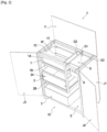
Tel que cela ressort de la
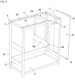
Le système de compostage I comporte un châssis A qui encadre un espace dédié au compostage II. Le châssis A peut se présenter sous différentes formes. Dans l'exemple illustré sur les dessins, le châssis A est formé par une structure tubulaire A1 destinée à être équipée de préférence de panneaux d'habillage J1, représentés sur la
Selon un mode de réalisation, l'espace dédié au compostage II est disposé à l'intérieur de l'espace délimité par les quatre tubes verticaux B du châssis A, entre l'avant et l'arrière du système de compostage I, et entre le dessus du système de compostage I et le plateau de fond E. Selon une variante illustrée sur la
À l'intérieur de l'espace dédié au compostage II sont disposés de manière superposée, un compartiment de compostage supérieur 1, au moins un compartiment de compostage intermédiaire 2 et un compartiment de compostage inférieur 3. Dans la suite de la description, les compartiments de compostage supérieur 1, intermédiaire 2 et inférieur 3 pourront être regroupés sous le nom de compartiments de compostage pour décrire des caractéristiques communes. Les compartiments de compostage 1, 2, 3 peuvent être réalisés de toute manière appropriée en métal, en bois, ou en plastique notamment transparent permettant à un utilisateur de visualiser l'intérieur des compartiments de compostage 1, 2, 3 depuis l'extérieur.Inside the space dedicated to composting II are arranged in a superimposed manner, an
Selon l'invention, le compartiment de compostage supérieur 1 se présente sous la forme d'un cadre de compostage 1A délimitant un espace tridimensionnel dont la projection verticale est par exemple un rectangle. Le cadre de compostage 1A comporte ainsi deux parois latérales opposées reliées par une paroi arrière et une paroi avant. Selon un mode de réalisation décrit sur les Figures, le compartiment de compostage supérieur 1 est monté fixe sur le châssis A. Le compartiment de compostage supérieur 1 possède un fond mobile 1B. À l'opposé de ce fond mobile 1B, le compartiment de compostage supérieur 1 admet une section de réception 1C, destinée à accueillir du compost récent composé de déchets organiques et/ou de matières sèches. La section de réception 1C est apte à être recouverte par une paroi de fermeture F, qui, selon le mode de réalisation décrit sur la
Le fond mobile 1B du compartiment de compostage supérieur 1 peut être manoeuvré à partir de la façade du système de compostage I en rentrant ou sortant par rapport à la paroi avant du cadre de compostage 1A. Le fond mobile 1B du compartiment de compostage supérieur 1 peut occuper deux positions, à savoir d'une part, une position ouverte délimitant une section d'évacuation 1D entre le bord arrière du fond mobile 1B et les deux parois latérales et la paroi arrière du cadre de compostage 1A, et d'autre part, une position fermée pour laquelle le fond mobile 18 obture la section d'évacuation 1D. Dans cette position fermée, le fond mobile 1B obture complètement l'espace inférieur du cadre de compostage 1A. Lors de l'utilisation du système de compostage I, le fond mobile 1B permet alors soit de retenir le compost dans le compartiment de compostage supérieur 1 en occupant une position fermée (
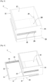
Selon un mode de réalisation décrit précisément sur les
Le fond mobile 2B du compartiment de compostage intermédiaire 2 peut être manoeuvré à partir de la façade du système de compostage I en rentrant ou sortant par rapport à la paroi avant du cadre de compostage 2A de ce compartiment 2. Le fond mobile 2B peut occuper deux positions, à savoir d'une part, une position ouverte délimitant une section d'évacuation 2D entre le bord arrière du fond mobile 2B et les deux parois latérales et la paroi arrière du cadre de compostage 2A, et d'autre part, une position fermée pour laquelle le fond mobile 2B obture la section d'évacuation 2D. Lors de l'utilisation du système de compostage I, le fond mobile 2B permet alors soit de retenir le compost dans le compartiment de compostage intermédiaire 2 en occupant une position fermée (
Selon l'invention, chaque compartiment de compostage intermédiaire 2 se présente sous la forme d'un tiroir. Le compartiment de compostage intermédiaire 2 est alors monté sur le châssis A par une liaison glissière 2E, réalisée de toute manière appropriée et présentant une direction horizontale de translation de l'avant à l'arrière du système de compostage I. Les Figures montrent un mode de réalisation de la liaison glissière 2E composée de deux rails fixés sur l'extérieur des deux parois latérales du cadre 2A du compartiment de compostage intermédiaire 2 coopérant avec deux rails complémentaires chacun fixé sur une traverse B2 disposées de part et d'autre du compartiment de compostage intermédiaire 2 et fixées d'un côté sur les demi-tubes verticaux B1 et de l'autre côté sur les deux tubes verticaux B. La liaison glissière 2E permet au compartiment de compostage intermédiaire 2 d'occuper soit une position rentrée, représentée notamment sur les
Selon l'invention, le compartiment de compostage inférieur 3 est situé au-dessous du compartiment de compostage intermédiaire 2 ou du compartiment de compostage intermédiaire 2 situé le plus bas de la série superposée. Le compartiment de compostage inférieur 3 se présente sous la forme d'un cadre de compostage 3A délimitant un espace tridimensionnel dont la projection verticale forme de préférence un rectangle. Ce cadre de compostage 3A comporte ainsi deux parois latérales opposées reliées par une paroi arrière et une paroi avant. Le compartiment de compostage inférieur 3 dispose d'un fond fixe 3B et est destiné à récupérer le compost mûr. Par exemple, le compartiment de compostage inférieur 3 est disposé libre sur le plateau de fond E du système de compostage I et est accessible depuis la façade du système de compostage I, permettant à un utilisateur de prendre facilement le compartiment de compostage inférieur 3 depuis l'extérieur.According to the invention, the
Les Figures décrivent un mode de réalisation préféré selon lequel le compartiment de compostage supérieur 1 est monté de manière amovible sur le châssis A. Le compartiment de compostage supérieur 1 peut occuper une position retirée pour laquelle le compartiment de compostage 1 n'est pas monté sur le châssis A et une position fixée pour laquelle le compartiment de compostage 1 est monté sur le châssis A. La position fixée est caractérisée en ce que le compartiment de compostage supérieur 1 est monté sur le châssis A à l'aide de deux épaulements 1Q, 1R s'étendant en saillie respectivement sur la paroi avant et sur la paroi arrière à la partie supérieure du compartiment de compostage supérieur 1. Ces épaulements 1Q, 1R sont destinés à s'emboîter respectivement dans des traverses de soutien K1, K2 du compartiment de compostage supérieur 1, chacune montée sur la partie supérieure du châssis A dans une gorge des tubes horizontaux C. Le compartiment de compostage supérieur 1 est amovible, c'est-à-dire qu'un utilisateur peut le retirer par le dessus de l'espace dédié au compostage II par exemple pour le nettoyer. Pour aider la manipulation du compartiment de compostage supérieur 1, les parois latérales opposées dudit compartiment de compostage supérieur 1 sont chacune pourvues d'une ouverture 1S permettant à un utilisateur d'y placer ses mains pour prendre le compartiment de compostage supérieur 1. Selon un autre mode de réalisation non illustré sur les Figures, le compartiment de compostage supérieur 1 est monté fixe sur le châssis A de sorte que ledit compartiment de compostage supérieur 1 fasse partie intégrante du châssis A. Un autre mode de réalisation non illustré sur les Figures est un compartiment de compostage supérieur 1 se présentant sous la forme d'un tiroir. Dans ce cas, le compartiment de compostage supérieur 1 est monté sur le châssis A de la même manière que le compartiment de compostage intermédiaire 2. De même, l'accès à l'intérieur du compartiment de compostage supérieur 1 se faisant en tirant le compartiment de compostage supérieur 1 en-dehors du châssis A, la paroi de fermeture F est fixée au châssis A. Ce mode de réalisation permet à un utilisateur d'utiliser le dessus de la paroi de fermeture F pour y placer une jardinière par exemple.The Figures describe a preferred embodiment in which the
Selon un mode de réalisation, le fond mobile 1B et le fond mobile 2B, équipant respectivement le compartiment de compostage supérieur 1 et le compartiment de compostage intermédiaire 2, comportent les mêmes éléments constitutifs. La description qui suit concerne les compartiments de compostage à fond mobile c'est-à-dire le compartiment de compostage supérieur 1 et le compartiment de compostage intermédiaire 2, même si la description est faite en relation des
Un compartiment de compostage à fond mobile (supérieur 1 et intermédiaire 2) comporte un fond mobile 1B, 2B formé d'une plaque de fond 1G, 2G équipée de deux bords latéraux opposés 1H, 1I et 2H, 2I reliés par un panneau de façade 1J, 2J. Lorsque le fond mobile 1B, 2B occupe une position fermée (
Selon une caractéristique avantageuse de réalisation, la plaque de fond 1G, 2G du fond mobile 1B, 2B des compartiments de compostage supérieur 1 et intermédiaire 2 est pourvue de trous d'évacuation respectivement 1M, 2M du jus de compost, destinés à être traversés par le jus de compost vers la section d'ouverture 2C, 3C du compartiment de compostage 2, 3 disposé en dessous. Selon un autre mode de réalisation du fond mobile 1B, 2B permettant de faciliter l'évacuation du jus de compost, la plaque de fond 1G, 2G est incurvée vers le bas en direction des trous d'évacuation 1M, 2M du jus de compost.According to an advantageous embodiment characteristic, the
Selon une autre caractéristique avantageuse de réalisation, un système de butée 1F, 2F est inclus dans la liaison glissière 1K, 2K entre le compartiment de compostage supérieur 1 et intermédiaire 2 et son fond mobile respectivement 1B, 2B. Le système de butée 1F, 2F étant réalisé de préférence par la butée de la liaison glissière 1K, 2K. La
Selon une caractéristique avantageuse de l'invention, chaque compartiment de compostage à fond mobile 1, 2 comporte un système d'étanchéité 1O, 1P et 2O, 2P pour maintenir les déchets organiques à l'intérieur des compartiments de compostage 1, 2 ayant un fond mobile lorsque le fond mobile est tiré vers une position ouverte. Comme représenté sur les Figures, le système d'étanchéité 1O, 1P et 2O, 2P est aménagé entre la plaque de fond 1G, 2G d'un fond mobile 1B, 2B et l'extrémité inférieure d'un cadre 1A, 2A du compartiment de compostage 1, 2. Selon une caractéristique avantageuse de réalisation, le système d'étanchéité 1O, 1P et 2O, 2P est aménagé entre la plaque de fond 1G, 2G d'un fond mobile 1B, 2B et l'extrémité inférieure de la paroi avant et également de préférence de la paroi arrière d'un cadre 1A, 2A. Un mode de réalisation préféré du système d'étanchéité 1O, 1P et 2O, 2P est une brosse d'étanchéité, mais d'autres modes de réalisation comme un joint d'étanchéité conviennent à ce système.According to an advantageous characteristic of the invention, each composting compartment with a
Selon une autre caractéristique avantageuse de réalisation, un système de butée 2N est inclus dans la liaison glissière 2E entre le compartiment de compostage intermédiaire 2 et le châssis A. Ce système de butée 2N est réalisé de toute manière appropriée, de préférence par la butée de la liaison glissière 2E, et est aménagé, comme illustré sur la
Selon un mode de réalisation de l'invention préféré décrit sur les Figures, la liaison glissière 2E entre le compartiment de compostage intermédiaire 2 et le châssis A demande à un utilisateur de tirer ou de pousser manuellement le compartiment de compostage 2 respectivement pour le sortir ou le rentrer dans l'espace dédié au compostage II. Pour aider l'utilisateur à tirer le compartiment de compostage intermédiaire 2, la paroi avant du cadre de compostage 2A est équipée d'une poignée 2L' ou d'un système analogue. Cette opération demande un peu de manipulation physique à l'utilisateur. Dans l'objectif de réduire les efforts de l'utilisateur au minimum et de pouvoir traiter des volumes plus importants de compost, un autre mode de réalisation envisageable non décrit sur les Figures est un système d'automatisation permettant de sortir et de rentrer le compartiment de compostage intermédiaire 2 dans l'espace dédié au compostage II sans intervention physique sur le compartiment de compostage 2. Ce système d'automatisation peut se présenter de manière préférée sous la forme d'un vérin double effet, permettant à un utilisateur de commander la sortie ou la rentrée du compartiment de compostage intermédiaire 2. De même, un système d'automatisation peut s'appliquer à un compartiment de compostage 1, 2 ayant un fond mobile, permettant à l'utilisateur de commander l'ouverture ou la fermeture du fond mobile 1B, 2B du compartiment de compostage 1, 2 correspondant.According to a preferred embodiment of the invention described in the Figures, the sliding
Selon une caractéristique préférée de l'invention, le système de compostage I peut comporter un système de filtration, non représenté sur les Figures, destiné à empêcher l'intrusion d'insectes à l'intérieur des compartiments de compostage 1, 2, 3. Ce système de filtration se présente sous la forme d'une maille obturant la section supérieure d'un compartiment de compostage, soit la section de réception pour le compartiment de compostage supérieur 1 et la section d'ouverture pour les compartiments de compostage intermédiaire 2 et inférieur 3. Il doit être compris que le système de filtration est amovible afin d'être enlevé avant le remplissage d'un compartiment de compostage 1, 2, 3.According to a preferred characteristic of the invention, the composting system I may comprise a filtration system, not shown in the Figures, intended to prevent the intrusion of insects inside the composting compartments 1, 2, 3. This filtration system is in the form of a mesh closing off the upper section of a composting compartment, namely the reception section for the
Selon une caractéristique avantageuse de l'invention, le système de compostage I comporte un bac de réserve G pour matières sèches. Les matières sèches peuvent être de la sciure, des copeaux de bois, des morceaux de cartons et sont utiles pour la maturation du compost. Les matières sèches sont utilisées pour être mélangées au compost à différents états de maturation donc dans les compartiments de compostage 1, 2, 3, et particulièrement aux déchets organiques récemment ajoutés c'est-à-dire dans le compartiment de compostage supérieur 1. Selon une caractéristique avantageuse de mise en oeuvre, les matières sèches peuvent être compressées pour se présenter sous la forme d'une cartouche destinée à être insérée dans le bac de réserve G. Il apparaît donc nécessaire de disposer d'un bac de réserve G pour matières sèches à proximité du compartiment de compostage supérieur 1, pour rappeler à l'utilisateur le besoin de rajouter ces matières sèches mais également pour faciliter leurs manipulations notamment pour réduire les risques de faire tomber des matières sèches en-dehors du compartiment de compostage supérieur 1. Pour cela, le bac de réserve G est monté sur le châssis A à proximité de l'espace dédié au compostage II, de manière que sa section supérieure G1 soit comprise dans le même plan horizontal que le plan de la section de réception 1C du compartiment de compostage supérieur 1. Dans l'exemple illustré, le bac de réserve G est monté dans l'espace intérieur du châssis A sur la droite du système de compostage I par rapport à la façade du système de compostage I, dans l'espace délimité entre les deux demi-tubes verticaux B1 et les deux tubes verticaux B situés à l'opposé de ceux délimitant l'espace dédié au compostage II. Le bac de réserve G se présente de manière préférée sous la forme de deux parois latérales reliées par une paroi avant et une paroi arrière, et d'un fond fixe. La section supérieure G1 du bac de réserve G est ouverte, elle représente une ouverture d'accès G1 pour l'utilisateur. Selon un mode de réalisation préféré, la matière du bac de réserve G est en tissu, mais tout autre type de matériau ayant la capacité de contenir de la matière peut être approprié.According to an advantageous characteristic of the invention, the composting system I comprises a reserve container G for dry materials. Dry materials can be sawdust, wood shavings, pieces of cardboard and are useful for the maturation of compost. The dry materials are used to be mixed with the compost at different states of maturation, therefore in the composting compartments 1, 2, 3, and particularly with the organic waste recently added, that is to say in the composting compartment. upper 1. According to an advantageous characteristic of implementation, the dry materials can be compressed to be in the form of a cartridge intended to be inserted into the reserve tank G. It therefore appears necessary to have a tank of reserve G for dry materials near the
Le mode de réalisation décrit sur les Figures montre un compartiment de compostage supérieur 1 monté de manière amovible sur le châssis A. Dans ce cas, le bac de réserve G est aussi monté de manière amovible sur le châssis A. Le bac de réserve G peut alors occuper une position retirée pour laquelle le bac de réserve G n'est pas monté sur le châssis A et une position fixée pour laquelle le bac de réserve G est monté sur le châssis A. La position fixée est caractérisée en ce que le bac de réserve G dispose de deux épaulements G2, G3 s'étendant en saillie sur les faces latérales opposées du bac de réserve G à sa partie supérieure, et destinés à s'emboîter respectivement dans des traverses de soutien K3, K4 du bac de réserve G chacune montée sur la partie supérieure du châssis A dans une gorge des tubes horizontaux C. Selon un autre mode de réalisation non-décrit sur les Figures dans lequel le compartiment de compostage supérieur 1 est de type tiroir, le bac de réserve G est aussi monté sur le châssis A par une liaison glissière d'axe horizontal. Dans ce cas, il est préféré que la liaison glissière entre le compartiment de compostage supérieur 1 et le châssis A et la liaison glissière entre le bac de réserve G et le châssis A soient liées, permettant de tirer à la fois le compartiment de compostage supérieur 1 et le bac de réserve G en-dehors du châssis A.The embodiment described in the Figures shows an
Lors d'interventions humaines à l'intérieur des compartiments de compostage 1, 2, 3, un utilisateur peut être amené à utiliser des outils pour travailler le compost comme par exemple une petite pelle, une petite griffe ou une paire de gants. Comme le montrent les Figures, le système de compostage I peut comporter un système d'accroche H pour outils. De manière préférée, ce système d'accroche H est fixé en haut du système de compostage I sur la structure tubulaire A1 du châssis A, et se présente sous la forme de crochets.During human interventions inside the composting compartments 1, 2, 3, a user may have to use tools to work the compost such as for example a small shovel, a small claw or a pair of gloves. As shown in the Figures, the composting system I can include a hooking system H for tools. Preferably, this attachment system H is fixed at the top of the composting system I on the tubular structure A1 of the frame A, and is in the form of hooks.
Une caractéristique du système de compostage I conforme à l'invention est que le système de compostage I peut s'intégrer dans des espaces extérieurs comme intérieurs. D'un point de vue pratique ou visuel, il apparait nécessaire d'intégrer le système de compostage I dans l'environnement qui l'entoure. Le système de compostage I dispose alors d'un système de fixation J pour permettre à des panneaux d'habillage J1 amovibles d'habiller les faces extérieures du système de compostage I. Le mode de réalisation du système de fixation J illustré sur les Figures comporte des aimants J2 fixés sur les panneaux d'habillage J1 aptes à être aimantés à la structure tubulaire A1 métallique du châssis A. Un autre mode de réalisation non décrit sur les Figures se présente sous la forme d'un système d'emboîtage élastique. Le châssis A est équipé sur l'extérieur de pièces femelles d'emboîtage élastique tandis que les panneaux d'habillage J1 sont équipés de pièces mâles d'emboîtage élastique disposés à des emplacements complémentaires des pièces femelles du système d'emboîtage élastique. Dans les deux modes de réalisation, un utilisateur peut facilement fixer, retirer et changer de panneau d'habillage J1 en fonction de l'environnement dans lequel le système de compostage I est installé. Selon un mode de réalisation préféré, deux portes J3, J4 sont montées en liaison pivot d'axe vertical sur la façade du système de compostage I pour permettre de le fermer complètement. Un autre mode de réalisation de la façade du système de compostage I peut être de placer temporairement des panneaux d'habillage J1, pourvus d'un système de fixation à aimants par exemple, pour habiller la façade du système de compostage I.A feature of the composting system I in accordance with the invention is that the composting system I can be integrated into both exterior and interior spaces. From a practical or visual point of view, it appears necessary to integrate the composting system I into the surrounding environment. The composting system I then has a fixing system J to allow removable covering panels J1 to cover the outer faces of the composting system I. The embodiment of the fixing system J illustrated in the Figures comprises magnets J2 fixed to the trim panels J1 capable of being magnetized to the metallic tubular structure A1 of the frame A. Another embodiment not described in the Figures is in the form of an elastic fitting system. Frame A is equipped on the outside with female elastic fitting parts while the trim panels J1 are equipped with male elastic fitting parts arranged at locations complementary to the female parts of the elastic fitting system. In both embodiments, a user can easily attach, remove and change the J1 cover panel depending on the environment in which the composting system I is installed. According to a preferred embodiment, two doors J3, J4 are mounted in pivot connection with a vertical axis on the facade of the composting system I to allow it to be closed completely. Another embodiment of the facade of the composting system I can be to temporarily place cladding panels J1, provided with a magnet fastening system for example, to dress the facade of the composting system I.
Afin d'obtenir un compost de bonne qualité, il est nécessaire que la maturation du compost se fasse dans des conditions favorables, en particulier la température et le taux d'humidité du système de compostage I. Dans ce sens, le système de compostage I peut comporter des capteurs, non représentés sur les Figures, notamment de température ou d'humidité à l'intérieur des compartiments de compostage supérieur 1 et intermédiaire 2 permettant à un utilisateur de vérifier les conditions de maturation du compost. Selon un mode de réalisation avantageux, le système de compostage 1 peut comporter un système connecté réalisant le transfert de données entre les capteurs placés dans l'espace dédié au compostage II et une interface utilisateur. Ce système connecté permet à l'utilisateur de connaître à l'aide de l'interface utilisateur des données en temps réel et de savoir ainsi si le compost est maintenu à bonne température, que son taux d'humidité est bon et qu'il est bien aéré.In order to obtain a good quality compost, it is necessary that the maturation of the compost takes place under favorable conditions, in particular the temperature and the humidity rate of the composting system I. In this sense, the composting system I may include sensors, not shown in the Figures, in particular for temperature or humidity inside the upper 1 and intermediate 2 composting compartments allowing a user to check the compost maturation conditions. According to an advantageous embodiment, the
Un autre objet de l'invention concerne un procédé de compostage de déchets organiques. Le procédé consiste à :
- insérer des déchets organiques par la section de réception 1C dans le compartiment de compostage supérieur 1 ;
- prendre de préférence des matières dans le bac de réserve G pour matières sèches et mélanger les matières avec les déchets organiques dans le compartiment de compostage supérieur 1 ;
- accéder à l'intérieur du compartiment de compostage supérieur 1 et vérifier l'état de maturation du compost ;
- tirer le fond mobile 1B du compartiment de compostage supérieur 1 vers l'extérieur du châssis A pour ouvrir la
section d'évacuation 1D pour faire tomber directement sans manipulation, le compost dans le compartiment de compostage intermédiaire 2 situé en dessous ; - tirer le compartiment de compostage intermédiaire 2 sous forme de tiroir pour accéder au compost, remuer le compost pour aérer, et humidifier le compost grâce au jus de compost issu du compartiment de compostage supérieur 1 situé au-dessus à travers les trous d'évacuation 1M ;
- tirer le fond mobile 2B du compartiment de compostage intermédiaire 2 vers l'extérieur du châssis A pour ouvrir la
section d'évacuation 2D pour faire tomber automatiquement sans opérations de manipulation complexes, le compost dans le compartiment de compostage inférieur 3 situé en dessous ; - répéter les opérations précédentes pour les différents compartiments de compostage supérieur 1
et intermédiaire 2 pour assurer la descente du compost vers un compartiment situé en dessous, en fonction de l'état de maturation du compost ; - et récupérer le compost mûr dans le compartiment de compostage inférieur 3.
- inserting organic waste through the receiving
section 1C into theupper composting compartment 1; - preferably take materials from the reserve bin G for dry materials and mix the materials with the organic waste in the
upper composting compartment 1; - access the interior of the
upper composting compartment 1 and check the state of maturation of the compost; - pull the
mobile bottom 1B from theupper composting compartment 1 towards the outside of the frame A to open theevacuation section 1D to drop directly without manipulation, the compost in theintermediate composting compartment 2 located below; - pull the
intermediate composting compartment 2 in the form of a drawer to access the compost, stir the compost to aerate, and moisten the compost with the compost juice from theupper composting compartment 1 located above through the evacuation holes 1M ; - pull the
mobile bottom 2B of theintermediate composting compartment 2 towards the outside of the frame A to open theevacuation section 2D to automatically drop without complex handling operations, the compost in thelower composting compartment 3 located below; - repeat the previous operations for the various upper 1 and intermediate 2 composting compartments to ensure the descent of the compost towards a compartment situated below, depending on the state of maturation of the compost;
- and collecting the mature compost in the
lower composting compartment 3.
Selon l'invention, le système de compostage I facilite la maturation de déchets organiques en proposant une solution assurant un compost homogène, aéré, avec un bon taux d'humidité. Les compartiments de compostage 1, 2, 3 représentent un avantage pour la maturation du compost car les matières sont mélangées au même stade de maturation, permettant un processus de maturation homogène. De plus, les compartiments de compostage supérieur 1 et intermédiaire 2 étant ouverts sur leur partie supérieure 1C, 2C et leur fond mobile 1B, 2B étant pourvu de trous d'évacuation 1M, 2M, l'air circule librement au sein de l'espace dédié au compostage II pendant le processus de maturation, assurant une bonne aération du compost. Les trous d'évacuation 1M, 2M présentent un avantage car ils permettent de maintenir un compost humide dans tous les compartiments de compostage 1, 2, 3. Enfin, le système de filtration assure une libre circulation des gaz au sein du système de compostage I tout en empêchant l'intrusion d'insectes au sein des compartiments de compostage 1, 2, 3.According to the invention, the composting system I facilitates the maturation of organic waste by proposing a solution ensuring a homogeneous, aerated compost, with a good level of humidity. The composting compartments 1, 2, 3 represent an advantage for the maturation of the compost because the materials are mixed at the same stage of maturation, allowing a homogeneous maturation process. In addition, the upper 1 and intermediate 2 composting compartments being open on their
Selon l'invention, le système de compostage 1 présente des avantages pour l'utilisateur. L'accès à l'intérieur de chaque compartiment de compostage 1, 2, 3 étant facile, un utilisateur peut intervenir sur le compost en fournissant peu d'effort, par exemple après avoir tiré hors du châssis A le compartiment de compostage intermédiaire 2. Un utilisateur peut vérifier visuellement l'état de chaque compost contenu dans les compartiments de compostage 1, 2, 3 et choisir de réaliser une opération de mélange, d'aération, d'humidification du compost ou de rajout de matières sèches dans un compartiment de compostage 1, 2, 3. De plus, la disposition des compartiments de compostage 1, 2, 3 est avantageuse car elle permet une transition du compost d'un compartiment de compostage à l'intérieur du compartiment de compostage situé en dessous sans opération de transvasement compliquée et sans occasionner de perte de compost à côté du compartiment de compostage. Les deux bords latéraux opposés 1H, 1I et 2H, 2I des fonds mobiles 1B, 2B présentent un avantage car ils servent à retenir le jus de compost à l'intérieur des compartiments de compostage supérieur 1 et intermédiaire 2 et donc à éviter un écoulement du jus de compost en dehors de ces compartiments de compostage 1, 2.According to the invention, the
De plus, le bac de réserve G pour matières sèches étant disposé de manière avantageuse à proximité du compartiment de compostage supérieur 1, cela permet à un utilisateur de prendre des matières sèches dans le bac de réserve G et de les mélanger avec les déchets organiques dans le compartiment de compostage supérieur 1 sans en renverser à côté. De plus, le bac de réserve G pour matières sèches étant disposé à proximité de l'espace dédié au compostage II, en cas de rajout nécessaire de matières sèches à l'intérieur des compartiments de compostage intermédiaire 2 et inférieur 3, l'utilisateur peut facilement prendre des matières sèches dans le bac de réserve G pour matières sèches et les mélanger au compost contenu dans les compartiments de compostage 2, 3. Les matières sèches présentent un avantage pour l'aération du compost et l'absorption de l'humidité avec un faible impact écologique, il est donc intéressant d'encourager l'utilisateur à utiliser ces matières sèches pour aider la maturation du compost.In addition, the reserve bin G for dry materials being advantageously arranged close to the
Claims (11)
- A system for composting (I) organic waste including a chassis (A) delimiting a space dedicated to the composting (II) of organic waste and in which are disposed;- an upper composting compartment (1), mounted on the chassis (A) and having, opposite a movable bottom (1B), a receiving section (1C) for the organic waste able to be obturated by a closing wall (F), the movable bottom (1B) occupying either an open position delimiting a discharge section (1D) for the organic waste by dropping the compost or a closed position to obdurate the discharge section (1D);- at least one drawer-type intermediate composting compartment (2), disposed below the upper composting compartment (1), and having, opposite a movable bottom (2B), an opening section (2C) adapted to receive the waste coming from the discharge section (1D) of the upper composting compartment (1), this intermediate composting compartment (2) being mounted on the chassis (A) by a sliding connection (2E) with a horizontal axis allowing it to occupy either a retracted position in which the opening section (2C) is located in line with the discharge section (1D) of the upper composting compartment (1) or a position pulled out of the chassis (A) to access the interior of the intermediate composting compartment (2), the movable bottom (2B) occupying either an open position delimiting a discharge section (2D) for the organic waste by dropping the compost or a position closed to obturate the discharge section (2D);- a composting compartment with movable bottom (1, 2) including a sliding connection (1K, 2K) between a frame (1A, 2A) and a movable bottom (1B, 2B), the sliding connection (1K, 2K) between the frame (1A, 2A) and the movable bottom (1B, 2B) of a composting compartment (1, 2) including rails fixed on the inside of the side edges (1H, 1I and 2H, 2I) of the movable bottom (1B, 2B) and cooperating with complementary rails fixed on the outside of the side walls of the frame (1A, 2A);- and a lower composting compartment (3), disposed at the bottom of the space dedicated to the composting (II), having an opening section (3C) located in line with the discharge section (2D) of the intermediate composting compartment (2) located above.
- The system according to the preceding claim, according to which the discharge section of a composting compartment is arranged such that its vertical projection is included in the opening section of the composting compartment located below.
- The system according to any of the preceding claims, according to which the closing wall (F) is a cover.
- The system according to any of the preceding claims, according to which the upper composting compartment (1) is of the drawer type, and the closing wall (F) is fixed.
- The system according to any of the preceding claims, according to which the movable bottom (1B, 2B) of a composting compartment (1, 2) is provided with discharge holes (1M, 2M) and to which the sliding connection (1K, 2K) between the frame (1A, 2A) and the movable bottom (1B, 2B) is provided with an abutment system (1F, 2F), so that in the pulled position of the composting compartment (1, 2), the discharge holes (1M, 2M) remain comprised in the opening section (2C, 3C) of the composting compartment (2, 3) located below.
- The system according to any of the preceding claims, according to which the movable bottom (1B, 2B) of a composting compartment (1, 2) is formed of a bottom plate (1G, 2G) equipped with two side edges (1H, 1I and 2H, 2I) connected by a front panel (1J, 2J), a sealing system (1O, 1P and 2O, 2P) being arranged between the movable bottom (1B, 2B) and the frame (1A, 2A) for keeping the organic waste inside the composting compartment (1, 2).
- The system according to any of the preceding claims, according to which the sliding connection (2E) between the drawer-type composting compartment (2) and the chassis (A) includes an abutment system (2N) preventing the composting compartment (2) from coming completely out of the chassis (A).
- The system according to any of the preceding claims, according to which the chassis (A) includes a storage tank (G) for dry matter, disposed in the vicinity of the space dedicated to the composting (II) and has an access opening (G1) extending in a plane substantially coplanar with the plane of the receiving section (1C) of the upper composting compartment (1).
- The system according to the preceding claim, according to which the storage tank (G) is configured to receive a cartridge of compressed dry matter.
- The system according to any of the preceding claims, according to which the chassis (A) includes a tubular structure (A1) equipped with trim panels (J1) mounted on the chassis (A) using a removable fixing system (J).
- A composting method implemented using a system according to any of claims 1 to 10, consisting of:- inserting organic waste into the upper composting compartment (1);- taking matter from the storage tank (G) for dry matter and mixing the matter with the organic waste in the upper composting compartment (1);- accessing the interior of the upper composting compartment (1) and checking the state of maturation of the compost;- pulling the movable bottom (1B) of the upper composting compartment (1) towards the outside of the chassis (A) to open the upper composting compartment (1) and to drop the compost into the intermediate composting compartment (2) located below;- pulling a drawer-type intermediate composting compartment (2) to access the compost, stirring the compost to aerate it, and moistening the compost with the compost juice transmitted from an upper composting compartment (1) to an intermediate composting compartment (2) located below, through the discharge holes (1M);- pulling the movable bottom (2B) of the intermediate composting compartment (2) towards the outside of the chassis (A) to open the intermediate composting compartment (2) and to drop the compost into the lower composting compartment (3);- repeating the operations to ensure the descent of the compost towards the lower composting compartments according to its state of maturation;- and recovering the mature compost in the lower composting compartment (3).
Applications Claiming Priority (1)
| Application Number | Priority Date | Filing Date | Title |
|---|---|---|---|
| FR2007924A FR3112772B1 (en) | 2020-07-27 | 2020-07-27 | Composting system for organic waste |
Publications (3)
| Publication Number | Publication Date |
|---|---|
| EP3945084A1 EP3945084A1 (en) | 2022-02-02 |
| EP3945084C0 EP3945084C0 (en) | 2023-07-12 |
| EP3945084B1 true EP3945084B1 (en) | 2023-07-12 |
Family
ID=73013669
Family Applications (1)
| Application Number | Title | Priority Date | Filing Date |
|---|---|---|---|
| EP21184209.1A Active EP3945084B1 (en) | 2020-07-27 | 2021-07-07 | Composting system for organic waste |
Country Status (4)
| Country | Link |
|---|---|
| EP (1) | EP3945084B1 (en) |
| ES (1) | ES2959489T3 (en) |
| FR (1) | FR3112772B1 (en) |
| PL (1) | PL3945084T3 (en) |
Family Cites Families (2)
| Publication number | Priority date | Publication date | Assignee | Title |
|---|---|---|---|---|
| GB0001267D0 (en) | 2000-01-21 | 2000-03-08 | West Edward V | Method of composting and container therefor |
| US7018831B2 (en) * | 2001-09-26 | 2006-03-28 | Biosystem Solutions, Inc. | Composting apparatus and method |
-
2020
- 2020-07-27 FR FR2007924A patent/FR3112772B1/en active Active
-
2021
- 2021-07-07 ES ES21184209T patent/ES2959489T3/en active Active
- 2021-07-07 PL PL21184209.1T patent/PL3945084T3/en unknown
- 2021-07-07 EP EP21184209.1A patent/EP3945084B1/en active Active
Also Published As
| Publication number | Publication date |
|---|---|
| PL3945084T3 (en) | 2024-02-05 |
| FR3112772B1 (en) | 2022-12-09 |
| EP3945084C0 (en) | 2023-07-12 |
| ES2959489T3 (en) | 2024-02-26 |
| FR3112772A1 (en) | 2022-01-28 |
| EP3945084A1 (en) | 2022-02-02 |
Similar Documents
| Publication | Publication Date | Title |
|---|---|---|
| US6209978B1 (en) | Waste organizing cabinet | |
| US20070200471A1 (en) | Clothes hamper cabinet | |
| CA2694829A1 (en) | A compost collection bin | |
| EP0385877A1 (en) | Cutlery basket for a dishwasher | |
| US5377907A (en) | Assembly for housing multiple waste receptacles | |
| US5322793A (en) | Composting bin | |
| EP3945084B1 (en) | Composting system for organic waste | |
| CA2695591A1 (en) | Cat litter box with 3-fold rotational symmetrical cleaning mechanism | |
| FR2979181A1 (en) | Container, useful for cultivating plants, comprises enclosure that is carried out by wall assembly including peripheral and lower walls and includes compartments, where one of compartments contains organic waste, plant and worm compost | |
| FR2718435A1 (en) | Composting bin with bottom drain valve | |
| EP0793060B1 (en) | Moisture-absorbing device | |
| CN209951183U (en) | Cleaning tool storage device and cleaning tool set | |
| FR3054405A1 (en) | COMPOSTING CULTURE DEVICE FOR THE VALORISATION OF ORGANIC WASTE AND THE CULTURE OF PLANTS | |
| CN212355163U (en) | Garden garbage bin | |
| FR2948359A1 (en) | Vermicomposter for transforming household organic wastes into juices and humus, comprises working trays stacked upon each other to receive wastes, a closing lid, a collection tray located beneath the working trays, and a filtering unit | |
| FR2765125A1 (en) | Selective collection of rubbish requiring sorting | |
| FR2777768A1 (en) | Assembly for religious candle-burning | |
| FR2632487A1 (en) | Window box (plant stand) with interchangeable element and reserve of water for irrigation by capillarity | |
| JP2000313501A (en) | Simple multi-purpose house | |
| CN217389515U (en) | Environment-friendly seedling growth device | |
| JP2020075857A (en) | Compost container and composting method using the same | |
| FR3000062A1 (en) | Vermicomposter, comprises a tank, an inlet opening for organic waste, a higher level for reception of waste, a lower level for reception of vermicompost, and a tilted plane connecting the lower level to the higher level | |
| JP3039108U (en) | Footwear storage | |
| FR2642270A1 (en) | Living aquatic picture | |
| JP2001208472A (en) | Container for drying garbage |
Legal Events
| Date | Code | Title | Description |
|---|---|---|---|
| PUAI | Public reference made under article 153(3) epc to a published international application that has entered the european phase |
Free format text: ORIGINAL CODE: 0009012 |
|
| STAA | Information on the status of an ep patent application or granted ep patent |
Free format text: STATUS: THE APPLICATION HAS BEEN PUBLISHED |
|
| AK | Designated contracting states |
Kind code of ref document: A1 Designated state(s): AL AT BE BG CH CY CZ DE DK EE ES FI FR GB GR HR HU IE IS IT LI LT LU LV MC MK MT NL NO PL PT RO RS SE SI SK SM TR |
|
| STAA | Information on the status of an ep patent application or granted ep patent |
Free format text: STATUS: REQUEST FOR EXAMINATION WAS MADE |
|
| 17P | Request for examination filed |
Effective date: 20220705 |
|
| RBV | Designated contracting states (corrected) |
Designated state(s): AL AT BE BG CH CY CZ DE DK EE ES FI FR GB GR HR HU IE IS IT LI LT LU LV MC MK MT NL NO PL PT RO RS SE SI SK SM TR |
|
| GRAP | Despatch of communication of intention to grant a patent |
Free format text: ORIGINAL CODE: EPIDOSNIGR1 |
|
| STAA | Information on the status of an ep patent application or granted ep patent |
Free format text: STATUS: GRANT OF PATENT IS INTENDED |
|
| INTG | Intention to grant announced |
Effective date: 20230124 |
|
| GRAS | Grant fee paid |
Free format text: ORIGINAL CODE: EPIDOSNIGR3 |
|
| GRAA | (expected) grant |
Free format text: ORIGINAL CODE: 0009210 |
|
| STAA | Information on the status of an ep patent application or granted ep patent |
Free format text: STATUS: THE PATENT HAS BEEN GRANTED |
|
| AK | Designated contracting states |
Kind code of ref document: B1 Designated state(s): AL AT BE BG CH CY CZ DE DK EE ES FI FR GB GR HR HU IE IS IT LI LT LU LV MC MK MT NL NO PL PT RO RS SE SI SK SM TR |
|
| REG | Reference to a national code |
Ref country code: CH Ref legal event code: EP |
|
| REG | Reference to a national code |
Ref country code: IE Ref legal event code: FG4D Free format text: LANGUAGE OF EP DOCUMENT: FRENCH |
|
| REG | Reference to a national code |
Ref country code: DE Ref legal event code: R096 Ref document number: 602021003381 Country of ref document: DE |
|
| U01 | Request for unitary effect filed |
Effective date: 20230726 |
|
| U07 | Unitary effect registered |
Designated state(s): AT BE BG DE DK EE FI FR IT LT LU LV MT NL PT SE SI Effective date: 20230731 |
|
| REG | Reference to a national code |
Ref country code: LT Ref legal event code: MG9D |
|
| PG25 | Lapsed in a contracting state [announced via postgrant information from national office to epo] |
Ref country code: GR Free format text: LAPSE BECAUSE OF FAILURE TO SUBMIT A TRANSLATION OF THE DESCRIPTION OR TO PAY THE FEE WITHIN THE PRESCRIBED TIME-LIMIT Effective date: 20231013 |
|
| PG25 | Lapsed in a contracting state [announced via postgrant information from national office to epo] |
Ref country code: IS Free format text: LAPSE BECAUSE OF FAILURE TO SUBMIT A TRANSLATION OF THE DESCRIPTION OR TO PAY THE FEE WITHIN THE PRESCRIBED TIME-LIMIT Effective date: 20231112 |
|
| PG25 | Lapsed in a contracting state [announced via postgrant information from national office to epo] |
Ref country code: RS Free format text: LAPSE BECAUSE OF FAILURE TO SUBMIT A TRANSLATION OF THE DESCRIPTION OR TO PAY THE FEE WITHIN THE PRESCRIBED TIME-LIMIT Effective date: 20230712 Ref country code: NO Free format text: LAPSE BECAUSE OF FAILURE TO SUBMIT A TRANSLATION OF THE DESCRIPTION OR TO PAY THE FEE WITHIN THE PRESCRIBED TIME-LIMIT Effective date: 20231012 Ref country code: IS Free format text: LAPSE BECAUSE OF FAILURE TO SUBMIT A TRANSLATION OF THE DESCRIPTION OR TO PAY THE FEE WITHIN THE PRESCRIBED TIME-LIMIT Effective date: 20231112 Ref country code: HR Free format text: LAPSE BECAUSE OF FAILURE TO SUBMIT A TRANSLATION OF THE DESCRIPTION OR TO PAY THE FEE WITHIN THE PRESCRIBED TIME-LIMIT Effective date: 20230712 Ref country code: GR Free format text: LAPSE BECAUSE OF FAILURE TO SUBMIT A TRANSLATION OF THE DESCRIPTION OR TO PAY THE FEE WITHIN THE PRESCRIBED TIME-LIMIT Effective date: 20231013 |
|
| REG | Reference to a national code |
Ref country code: ES Ref legal event code: FG2A Ref document number: 2959489 Country of ref document: ES Kind code of ref document: T3 Effective date: 20240226 |
|
| PG25 | Lapsed in a contracting state [announced via postgrant information from national office to epo] |
Ref country code: SM Free format text: LAPSE BECAUSE OF FAILURE TO SUBMIT A TRANSLATION OF THE DESCRIPTION OR TO PAY THE FEE WITHIN THE PRESCRIBED TIME-LIMIT Effective date: 20230712 Ref country code: RO Free format text: LAPSE BECAUSE OF FAILURE TO SUBMIT A TRANSLATION OF THE DESCRIPTION OR TO PAY THE FEE WITHIN THE PRESCRIBED TIME-LIMIT Effective date: 20230712 Ref country code: CZ Free format text: LAPSE BECAUSE OF FAILURE TO SUBMIT A TRANSLATION OF THE DESCRIPTION OR TO PAY THE FEE WITHIN THE PRESCRIBED TIME-LIMIT Effective date: 20230712 Ref country code: SK Free format text: LAPSE BECAUSE OF FAILURE TO SUBMIT A TRANSLATION OF THE DESCRIPTION OR TO PAY THE FEE WITHIN THE PRESCRIBED TIME-LIMIT Effective date: 20230712 |