EP3944980B1 - Ensemble de traction constitué d'une locomotive et d'un tender ; procédé associé - Google Patents
Ensemble de traction constitué d'une locomotive et d'un tender ; procédé associé Download PDFInfo
- Publication number
- EP3944980B1 EP3944980B1 EP21187595.0A EP21187595A EP3944980B1 EP 3944980 B1 EP3944980 B1 EP 3944980B1 EP 21187595 A EP21187595 A EP 21187595A EP 3944980 B1 EP3944980 B1 EP 3944980B1
- Authority
- EP
- European Patent Office
- Prior art keywords
- locomotive
- roof line
- switching device
- tender
- traction
- Prior art date
- Legal status (The legal status is an assumption and is not a legal conclusion. Google has not performed a legal analysis and makes no representation as to the accuracy of the status listed.)
- Active
Links
Images
Classifications
-
- B—PERFORMING OPERATIONS; TRANSPORTING
- B60—VEHICLES IN GENERAL
- B60L—PROPULSION OF ELECTRICALLY-PROPELLED VEHICLES; SUPPLYING ELECTRIC POWER FOR AUXILIARY EQUIPMENT OF ELECTRICALLY-PROPELLED VEHICLES; ELECTRODYNAMIC BRAKE SYSTEMS FOR VEHICLES IN GENERAL; MAGNETIC SUSPENSION OR LEVITATION FOR VEHICLES; MONITORING OPERATING VARIABLES OF ELECTRICALLY-PROPELLED VEHICLES; ELECTRIC SAFETY DEVICES FOR ELECTRICALLY-PROPELLED VEHICLES
- B60L5/00—Current collectors for power supply lines of electrically-propelled vehicles
- B60L5/18—Current collectors for power supply lines of electrically-propelled vehicles using bow-type collectors in contact with trolley wire
- B60L5/20—Details of contact bow
-
- B—PERFORMING OPERATIONS; TRANSPORTING
- B60—VEHICLES IN GENERAL
- B60L—PROPULSION OF ELECTRICALLY-PROPELLED VEHICLES; SUPPLYING ELECTRIC POWER FOR AUXILIARY EQUIPMENT OF ELECTRICALLY-PROPELLED VEHICLES; ELECTRODYNAMIC BRAKE SYSTEMS FOR VEHICLES IN GENERAL; MAGNETIC SUSPENSION OR LEVITATION FOR VEHICLES; MONITORING OPERATING VARIABLES OF ELECTRICALLY-PROPELLED VEHICLES; ELECTRIC SAFETY DEVICES FOR ELECTRICALLY-PROPELLED VEHICLES
- B60L50/00—Electric propulsion with power supplied within the vehicle
- B60L50/50—Electric propulsion with power supplied within the vehicle using propulsion power supplied by batteries or fuel cells
- B60L50/51—Electric propulsion with power supplied within the vehicle using propulsion power supplied by batteries or fuel cells characterised by AC-motors
-
- B—PERFORMING OPERATIONS; TRANSPORTING
- B60—VEHICLES IN GENERAL
- B60L—PROPULSION OF ELECTRICALLY-PROPELLED VEHICLES; SUPPLYING ELECTRIC POWER FOR AUXILIARY EQUIPMENT OF ELECTRICALLY-PROPELLED VEHICLES; ELECTRODYNAMIC BRAKE SYSTEMS FOR VEHICLES IN GENERAL; MAGNETIC SUSPENSION OR LEVITATION FOR VEHICLES; MONITORING OPERATING VARIABLES OF ELECTRICALLY-PROPELLED VEHICLES; ELECTRIC SAFETY DEVICES FOR ELECTRICALLY-PROPELLED VEHICLES
- B60L50/00—Electric propulsion with power supplied within the vehicle
- B60L50/50—Electric propulsion with power supplied within the vehicle using propulsion power supplied by batteries or fuel cells
- B60L50/53—Electric propulsion with power supplied within the vehicle using propulsion power supplied by batteries or fuel cells in combination with an external power supply, e.g. from overhead contact lines
-
- B—PERFORMING OPERATIONS; TRANSPORTING
- B60—VEHICLES IN GENERAL
- B60L—PROPULSION OF ELECTRICALLY-PROPELLED VEHICLES; SUPPLYING ELECTRIC POWER FOR AUXILIARY EQUIPMENT OF ELECTRICALLY-PROPELLED VEHICLES; ELECTRODYNAMIC BRAKE SYSTEMS FOR VEHICLES IN GENERAL; MAGNETIC SUSPENSION OR LEVITATION FOR VEHICLES; MONITORING OPERATING VARIABLES OF ELECTRICALLY-PROPELLED VEHICLES; ELECTRIC SAFETY DEVICES FOR ELECTRICALLY-PROPELLED VEHICLES
- B60L53/00—Methods of charging batteries, specially adapted for electric vehicles; Charging stations or on-board charging equipment therefor; Exchange of energy storage elements in electric vehicles
- B60L53/10—Methods of charging batteries, specially adapted for electric vehicles; Charging stations or on-board charging equipment therefor; Exchange of energy storage elements in electric vehicles characterised by the energy transfer between the charging station and the vehicle
- B60L53/14—Conductive energy transfer
-
- B—PERFORMING OPERATIONS; TRANSPORTING
- B60—VEHICLES IN GENERAL
- B60L—PROPULSION OF ELECTRICALLY-PROPELLED VEHICLES; SUPPLYING ELECTRIC POWER FOR AUXILIARY EQUIPMENT OF ELECTRICALLY-PROPELLED VEHICLES; ELECTRODYNAMIC BRAKE SYSTEMS FOR VEHICLES IN GENERAL; MAGNETIC SUSPENSION OR LEVITATION FOR VEHICLES; MONITORING OPERATING VARIABLES OF ELECTRICALLY-PROPELLED VEHICLES; ELECTRIC SAFETY DEVICES FOR ELECTRICALLY-PROPELLED VEHICLES
- B60L53/00—Methods of charging batteries, specially adapted for electric vehicles; Charging stations or on-board charging equipment therefor; Exchange of energy storage elements in electric vehicles
- B60L53/20—Methods of charging batteries, specially adapted for electric vehicles; Charging stations or on-board charging equipment therefor; Exchange of energy storage elements in electric vehicles characterised by converters located in the vehicle
- B60L53/22—Constructional details or arrangements of charging converters specially adapted for charging electric vehicles
-
- B—PERFORMING OPERATIONS; TRANSPORTING
- B60—VEHICLES IN GENERAL
- B60L—PROPULSION OF ELECTRICALLY-PROPELLED VEHICLES; SUPPLYING ELECTRIC POWER FOR AUXILIARY EQUIPMENT OF ELECTRICALLY-PROPELLED VEHICLES; ELECTRODYNAMIC BRAKE SYSTEMS FOR VEHICLES IN GENERAL; MAGNETIC SUSPENSION OR LEVITATION FOR VEHICLES; MONITORING OPERATING VARIABLES OF ELECTRICALLY-PROPELLED VEHICLES; ELECTRIC SAFETY DEVICES FOR ELECTRICALLY-PROPELLED VEHICLES
- B60L55/00—Arrangements for supplying energy stored within a vehicle to a power network, i.e. vehicle-to-grid [V2G] arrangements
-
- B—PERFORMING OPERATIONS; TRANSPORTING
- B60—VEHICLES IN GENERAL
- B60L—PROPULSION OF ELECTRICALLY-PROPELLED VEHICLES; SUPPLYING ELECTRIC POWER FOR AUXILIARY EQUIPMENT OF ELECTRICALLY-PROPELLED VEHICLES; ELECTRODYNAMIC BRAKE SYSTEMS FOR VEHICLES IN GENERAL; MAGNETIC SUSPENSION OR LEVITATION FOR VEHICLES; MONITORING OPERATING VARIABLES OF ELECTRICALLY-PROPELLED VEHICLES; ELECTRIC SAFETY DEVICES FOR ELECTRICALLY-PROPELLED VEHICLES
- B60L9/00—Electric propulsion with power supply external to the vehicle
- B60L9/02—Electric propulsion with power supply external to the vehicle using DC motors
- B60L9/08—Electric propulsion with power supply external to the vehicle using DC motors fed from AC supply lines
-
- B—PERFORMING OPERATIONS; TRANSPORTING
- B60—VEHICLES IN GENERAL
- B60L—PROPULSION OF ELECTRICALLY-PROPELLED VEHICLES; SUPPLYING ELECTRIC POWER FOR AUXILIARY EQUIPMENT OF ELECTRICALLY-PROPELLED VEHICLES; ELECTRODYNAMIC BRAKE SYSTEMS FOR VEHICLES IN GENERAL; MAGNETIC SUSPENSION OR LEVITATION FOR VEHICLES; MONITORING OPERATING VARIABLES OF ELECTRICALLY-PROPELLED VEHICLES; ELECTRIC SAFETY DEVICES FOR ELECTRICALLY-PROPELLED VEHICLES
- B60L9/00—Electric propulsion with power supply external to the vehicle
- B60L9/16—Electric propulsion with power supply external to the vehicle using AC induction motors
- B60L9/30—Electric propulsion with power supply external to the vehicle using AC induction motors fed from different kinds of power-supply lines
-
- B—PERFORMING OPERATIONS; TRANSPORTING
- B61—RAILWAYS
- B61C—LOCOMOTIVES; MOTOR RAILCARS
- B61C17/00—Arrangement or disposition of parts; Details or accessories not otherwise provided for; Use of control gear and control systems
- B61C17/06—Power storing devices
-
- B—PERFORMING OPERATIONS; TRANSPORTING
- B61—RAILWAYS
- B61C—LOCOMOTIVES; MOTOR RAILCARS
- B61C3/00—Electric locomotives or railcars
- B61C3/02—Electric locomotives or railcars with electric accumulators
-
- B—PERFORMING OPERATIONS; TRANSPORTING
- B61—RAILWAYS
- B61C—LOCOMOTIVES; MOTOR RAILCARS
- B61C9/00—Locomotives or motor railcars characterised by the type of transmission system used; Transmission systems specially adapted for locomotives or motor railcars
- B61C9/38—Transmission systems in or for locomotives or motor railcars with electric motor propulsion
-
- B—PERFORMING OPERATIONS; TRANSPORTING
- B60—VEHICLES IN GENERAL
- B60L—PROPULSION OF ELECTRICALLY-PROPELLED VEHICLES; SUPPLYING ELECTRIC POWER FOR AUXILIARY EQUIPMENT OF ELECTRICALLY-PROPELLED VEHICLES; ELECTRODYNAMIC BRAKE SYSTEMS FOR VEHICLES IN GENERAL; MAGNETIC SUSPENSION OR LEVITATION FOR VEHICLES; MONITORING OPERATING VARIABLES OF ELECTRICALLY-PROPELLED VEHICLES; ELECTRIC SAFETY DEVICES FOR ELECTRICALLY-PROPELLED VEHICLES
- B60L2200/00—Type of vehicles
- B60L2200/26—Rail vehicles
-
- B—PERFORMING OPERATIONS; TRANSPORTING
- B60—VEHICLES IN GENERAL
- B60L—PROPULSION OF ELECTRICALLY-PROPELLED VEHICLES; SUPPLYING ELECTRIC POWER FOR AUXILIARY EQUIPMENT OF ELECTRICALLY-PROPELLED VEHICLES; ELECTRODYNAMIC BRAKE SYSTEMS FOR VEHICLES IN GENERAL; MAGNETIC SUSPENSION OR LEVITATION FOR VEHICLES; MONITORING OPERATING VARIABLES OF ELECTRICALLY-PROPELLED VEHICLES; ELECTRIC SAFETY DEVICES FOR ELECTRICALLY-PROPELLED VEHICLES
- B60L2200/00—Type of vehicles
- B60L2200/28—Trailers
-
- Y—GENERAL TAGGING OF NEW TECHNOLOGICAL DEVELOPMENTS; GENERAL TAGGING OF CROSS-SECTIONAL TECHNOLOGIES SPANNING OVER SEVERAL SECTIONS OF THE IPC; TECHNICAL SUBJECTS COVERED BY FORMER USPC CROSS-REFERENCE ART COLLECTIONS [XRACs] AND DIGESTS
- Y02—TECHNOLOGIES OR APPLICATIONS FOR MITIGATION OR ADAPTATION AGAINST CLIMATE CHANGE
- Y02E—REDUCTION OF GREENHOUSE GAS [GHG] EMISSIONS, RELATED TO ENERGY GENERATION, TRANSMISSION OR DISTRIBUTION
- Y02E60/00—Enabling technologies; Technologies with a potential or indirect contribution to GHG emissions mitigation
-
- Y—GENERAL TAGGING OF NEW TECHNOLOGICAL DEVELOPMENTS; GENERAL TAGGING OF CROSS-SECTIONAL TECHNOLOGIES SPANNING OVER SEVERAL SECTIONS OF THE IPC; TECHNICAL SUBJECTS COVERED BY FORMER USPC CROSS-REFERENCE ART COLLECTIONS [XRACs] AND DIGESTS
- Y02—TECHNOLOGIES OR APPLICATIONS FOR MITIGATION OR ADAPTATION AGAINST CLIMATE CHANGE
- Y02T—CLIMATE CHANGE MITIGATION TECHNOLOGIES RELATED TO TRANSPORTATION
- Y02T10/00—Road transport of goods or passengers
- Y02T10/60—Other road transportation technologies with climate change mitigation effect
- Y02T10/70—Energy storage systems for electromobility, e.g. batteries
-
- Y—GENERAL TAGGING OF NEW TECHNOLOGICAL DEVELOPMENTS; GENERAL TAGGING OF CROSS-SECTIONAL TECHNOLOGIES SPANNING OVER SEVERAL SECTIONS OF THE IPC; TECHNICAL SUBJECTS COVERED BY FORMER USPC CROSS-REFERENCE ART COLLECTIONS [XRACs] AND DIGESTS
- Y02—TECHNOLOGIES OR APPLICATIONS FOR MITIGATION OR ADAPTATION AGAINST CLIMATE CHANGE
- Y02T—CLIMATE CHANGE MITIGATION TECHNOLOGIES RELATED TO TRANSPORTATION
- Y02T10/00—Road transport of goods or passengers
- Y02T10/60—Other road transportation technologies with climate change mitigation effect
- Y02T10/7072—Electromobility specific charging systems or methods for batteries, ultracapacitors, supercapacitors or double-layer capacitors
-
- Y—GENERAL TAGGING OF NEW TECHNOLOGICAL DEVELOPMENTS; GENERAL TAGGING OF CROSS-SECTIONAL TECHNOLOGIES SPANNING OVER SEVERAL SECTIONS OF THE IPC; TECHNICAL SUBJECTS COVERED BY FORMER USPC CROSS-REFERENCE ART COLLECTIONS [XRACs] AND DIGESTS
- Y02—TECHNOLOGIES OR APPLICATIONS FOR MITIGATION OR ADAPTATION AGAINST CLIMATE CHANGE
- Y02T—CLIMATE CHANGE MITIGATION TECHNOLOGIES RELATED TO TRANSPORTATION
- Y02T30/00—Transportation of goods or passengers via railways, e.g. energy recovery or reducing air resistance
-
- Y—GENERAL TAGGING OF NEW TECHNOLOGICAL DEVELOPMENTS; GENERAL TAGGING OF CROSS-SECTIONAL TECHNOLOGIES SPANNING OVER SEVERAL SECTIONS OF THE IPC; TECHNICAL SUBJECTS COVERED BY FORMER USPC CROSS-REFERENCE ART COLLECTIONS [XRACs] AND DIGESTS
- Y02—TECHNOLOGIES OR APPLICATIONS FOR MITIGATION OR ADAPTATION AGAINST CLIMATE CHANGE
- Y02T—CLIMATE CHANGE MITIGATION TECHNOLOGIES RELATED TO TRANSPORTATION
- Y02T90/00—Enabling technologies or technologies with a potential or indirect contribution to GHG emissions mitigation
- Y02T90/10—Technologies relating to charging of electric vehicles
- Y02T90/14—Plug-in electric vehicles
-
- Y—GENERAL TAGGING OF NEW TECHNOLOGICAL DEVELOPMENTS; GENERAL TAGGING OF CROSS-SECTIONAL TECHNOLOGIES SPANNING OVER SEVERAL SECTIONS OF THE IPC; TECHNICAL SUBJECTS COVERED BY FORMER USPC CROSS-REFERENCE ART COLLECTIONS [XRACs] AND DIGESTS
- Y04—INFORMATION OR COMMUNICATION TECHNOLOGIES HAVING AN IMPACT ON OTHER TECHNOLOGY AREAS
- Y04S—SYSTEMS INTEGRATING TECHNOLOGIES RELATED TO POWER NETWORK OPERATION, COMMUNICATION OR INFORMATION TECHNOLOGIES FOR IMPROVING THE ELECTRICAL POWER GENERATION, TRANSMISSION, DISTRIBUTION, MANAGEMENT OR USAGE, i.e. SMART GRIDS
- Y04S10/00—Systems supporting electrical power generation, transmission or distribution
- Y04S10/12—Monitoring or controlling equipment for energy generation units, e.g. distributed energy generation [DER] or load-side generation
- Y04S10/126—Monitoring or controlling equipment for energy generation units, e.g. distributed energy generation [DER] or load-side generation the energy generation units being or involving electric vehicles [EV] or hybrid vehicles [HEV], i.e. power aggregation of EV or HEV, vehicle to grid arrangements [V2G]
Definitions
- the present invention relates to locomotives of the single-current, dual-current, tri-current or more types, operating by capturing at least one electrical power, alternating or direct.
- a dual-current locomotive is capable of sensing either a first electrical power, in particular single-phase, by means of a first dedicated pantograph, or a second electrical power, in particular continuous, by means of a second dedicated pantograph.
- Such energy storage means are, for example, batteries, supercapacitors, fuel cells, etc.
- Locomotives are known to be equipped with on-board energy storage means. However, these means are integrated from the design of the locomotive, in its power circuit and/or have a reduced capacity/autonomy.
- the document EP 2 810 813 A1 discloses a traction assembly comprising a locomotive, the locomotive comprising a roof line, electrically connected to at least one pantograph, a control system and a feeler circuit, the control system being capable of controlling, as a function of the instantaneous properties of a voltage on the roof line detected by the feeler circuit, the open or closed state of at least one switch device placed between the roof line and a power supply circuit of the traction motors of the locomotive.
- This document also discloses the carrying on board the locomotive of energy storage means. These are connected to the common DC bus of the power supply circuit of the traction motors of the locomotive.
- the document EP 1 977 948 A2 plans, without further details, to place a battery in a passenger car, different from the locomotive.
- the document EP 2 810 813 A1 discloses an assembly resulting from the coupling of a locomotive and a tender, the tender integrating an electrical energy storage system connected to the common DC bus of the power supply circuit of the traction motors of the locomotive. In braking mode, the system recovers part of the energy generated by the motors and, in traction mode, supplies the motors with all or part of the energy necessary for traction.
- the aim of the invention is therefore to address this problem, in particular by proposing a simple solution to implement which allows modernization of existing locomotives at low cost.
- the invention relates to a traction assembly and a method for selecting an electrical power source according to the appended claims.
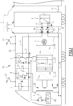
- FIG. 1 represents a train 1 consisting of the coupling of a traction unit 2 with one or more wagons 3, such as passenger cars.
- the train includes a control system 40 capable of controlling the various equipment on board the train.
- This control system 40 is notably called a TCMS system for “train control and management system”.
- the traction assembly 2 itself consists of the coupling of a locomotive 4, for example of the dual-current type, and a tender 6.
- a tender is an auxiliary wagon placed after a locomotive and which contains a reserve of fuel necessary for supplying it.
- the tender 6 carries energy storage means, generally referenced by the number 8, capable of delivering a direct electric current.
- energy storage means capable of delivering a direct electric current.
- These means 8 are for example constituted by a source (such as batteries, supercapacitors, fuel cells, mixed (fuel cell/battery), or any device known to those skilled in the art) and a current converter, such as a direct-direct converter or alternatively a direct-alternating converter.
- the energy storage means 8 comprise a first terminal 12 and a second terminal 13. The latter is advantageously electrically connected to a point of the tender 6 brought to a reference potential.
- Locomotive 4 has a power circuit 20 for supplying the electric traction motors of locomotive 4. On the figure 1 , only one engine 5 is shown, but a locomotive usually has two or four.
- Circuit 20 allows current to be captured from an overhead line, such as a catenary (not shown in the figure 1 ).
- a dual-current locomotive is shown and circuit 20 therefore makes it possible to pick up either a single-phase current or a direct current from a point of contact with a power source, such as a catenary.
- the power circuit 20 comprises an earth line 19, electrically connected to a point brought to a reference potential.
- the power circuit 20 comprises, on the roof of the locomotive 4, a first pantograph dedicated to the capture of a single-phase current, or AC pantograph 21, and advantageously a second pantograph dedicated to the capture of a direct current, or DC pantograph 22.
- the power circuit comprises only one of the first and second pantographs or more than two pantographs and the power circuit is adapted accordingly.
- Each pantograph 21, 22 is electrically connected to a roof line 23.
- Roof line 23 extends along the roof of locomotive 4 between two end points A and D.
- a sensing device 24 is electrically connected to the roof line 23, for example at the front end point A. This device has the function of detecting, at each instant, the properties of the potential to which the roof line 23 is brought and to transmit this information to the control system 40.
- control system 40 controls the state of the various equipment, in particular the opening or closing of isolation devices 31 and 32 presented below in detail, to properly route the electrical power to the motors.
- the roof line 23 is electrically connected, through a single-phase isolation device - AC 31, to a point F constituting a first terminal of the primary of a transformer 25.
- the second terminal of the primary of transformer 25 is electrically connected to the earth line 19.
- the secondary of transformer 25 is connected to the input of a single-phase - DC converter 26.
- the direct current delivered at the output of the converter 26 is applied to a first input of a filtering device 27.
- the filtered direct current delivered at the output of the filtering device 27 is applied to the input of an inverter 28.
- the function of the inverter 28 is then to convert a filtered direct current into a three-phase current suitable for supplying the motor 5.
- the locomotive having several motors, it has as many conversion chains, each conversion chain being made up of a single-phase - DC converter (connected to the secondary of transformer 25), a filtering device and an inverter as described above.
- the roof line 23 is electrically connected, through a continuous isolation device - DC 32, to a point G constituting a second input of each of the filtering devices 27 of the locomotive power supply chains.
- an inductance 37 is interposed between the DC isolation device 32 and the point G.
- the direct current delivered at the output of a filtering device 27 is then applied to the input of the inverter 28 in order to be transformed into a three-phase current supplying the corresponding motor 5.
- the AC 31 isolation device comprises a single-phase isolation contactor - AC 33 and a single-phase circuit breaker - AC 35, connected in parallel to each other.
- one terminal of the AC 33 isolation contactor and one terminal of the AC 35 circuit breaker are connected to a point B of the roof line 23 and the other terminal of the AC 33 isolation contactor and the other terminal of AC 35 circuit breaker are connected to point F.
- the control system 40 is capable of controlling the open or closed state of the AC circuit breaker 35 depending on the type (alternating/direct) and the voltage level detected by the sensing circuit 24 at the line 23.
- the control system 40 is capable of controlling the closing of the AC circuit breaker 35 if the sensing circuit detects an alternating voltage of 25kV.
- the AC 33 isolation contactor which is suitable for bringing the roof line 23 to earth potential is intended to be controlled, preferably manually, between its closed state and its open state.
- the AC 33 isolation contactor is in particular intended to be controlled manually in the closed earthing state via a handling key, during an earthing operation of the line 23.
- the DC 32 isolation device comprises, in series, a continuous isolation contactor - DC 34 and a continuous circuit breaker - DC 36.
- one terminal of the DC isolating contactor 34 is connected to a point C of the roof line 23 and the other terminal of the DC isolating contactor 34 is connected to an intermediate point E.
- One terminal of the DC circuit breaker 36 is connected to the intermediate point E and the other terminal of the DC circuit breaker 36 is connected to the inductor 37.
- the control system 40 is capable of controlling the open or closed state of the DC circuit breaker 36 depending on the type (AC/DC) and the voltage level detected by the sensing circuit 24 at the line 23.
- the control system 40 is capable of controlling the closing of the DC circuit breaker 36 if the sensing circuit detects a DC voltage of 1.5 kV.
- control system 40 is capable of controlling the open or closed state of the DC isolation contactor 34 when a direct voltage is supplied on the line 23.
- the driver for example, at an interface with the control system 40, senses that he is on a portion of track with a direct power supply and the control system 40 controls the closing of the DC isolation contactor 34.
- Other equipment may be provided, such as lightning protection devices, means of isolating pantographs, systems for measuring the captured power, etc.
- the tender 6 is mechanically coupled to the locomotive 4 by a coupling link 10.
- the tender 6 is furthermore electrically coupled to the locomotive 4 so that the energy storage means 8 can supply electrical power to the traction motors 5 of the locomotive 4.
- dedicated connectors 14 and 15 are provided on a front face of the body of the tender 6. They are respectively electrically connected to the first terminal 12 and to the second terminal 13 of the means 8.
- the tender comprises a safety circuit breaker between the terminal 12 and the connector 14.
- Dedicated connectors 44 and 45 are also provided on the locomotive body 4, for example on each of the end faces of the locomotive body, in order to be able to electrically connect the tender to the locomotive regardless of the direction of the locomotive (turning).
- the electrical connection between the tender 6 and the locomotive 4 is made by a first electrical cable 54, coupled on the one hand to the connector 14 of the tender and on the other hand to the connector 44 of the locomotive, and by a second electrical cable 55 coupled on the one hand to the connector 15 of the tender and on the other hand to the connector 45 of the locomotive.
- one or more high-voltage cables 46 connect the connector 44 to the roof line 23.
- the high-voltage cable 46 is advantageously connected to the intermediate point E so that it can be isolated or connected to the roof line 23 depending on the open or closed state of the DC isolation contactor 34.
- the cable 46 is advantageously connected to the input of the single-phase circuit breaker 35 and an isolating contactor is for example provided between the roof line 23 and the single-phase circuit breaker 35.
- the high-voltage cable 46 runs outside the body of the locomotive 4, on the roof of the locomotive. It can, depending on the configuration of the engine, be installed inside the locomotive.
- One or more earth cables 47 connect the connector 45 to the earth line 19 of the locomotive 4. As a result, the tender and the locomotive share the same reference potential.
- the information corresponding to the state of the selector 60, and consequently to the operating mode selected by the driver, is transmitted to the control system 40 which is capable of controlling the movement of the pantographs and/or configuring the power circuit 20 as a function of this information.
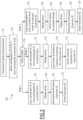
- control system 40 is programmed to implement the method of selecting an electrical power source shown in the figure 2 when changing the operating mode.
- the method 100 begins when, at step 110, the driver modifies the current operating mode, i.e. the power source to be used for powering the traction motors, by selecting a new operating mode using the selector 60.
- the control system 40 and the tender therefore receive information indicative of the new operating mode.
- step 120 the AC and DC pantographs are lowered and the circuit breakers 35, 36 and the isolating contactor 34 are switched to the open state.
- step 130 the value of the new operating mode is tested.
- step 141 the AC pantograph is raised so as to be brought into contact with a catenary delivering a single-phase current.
- the DC pantograph is then blocked in the lowered position and the contactor 34 is in an isolating position in which it isolates the intermediate point E from the potential of the roof line 23.
- the circuit breaker 36 is advantageously maintained in the open state.
- the sensing circuit 24 detects that the roof line 23 is brought to a single-phase potential, within an acceptable voltage range.
- control system 40 authorizes the closing of the AC circuit breaker 35, while keeping the DC circuit breaker 36 open.
- the contactor 34 is also kept in its isolation position.
- step 147 the AC circuit breaker 35 is closed. Under these conditions, the single-phase current captured by the AC pantograph 21 is applied, via the transformer 25, to the input of each of the power supply chains.
- step 151 the DC pantograph 22 is placed in the raised position so as to be brought into contact with a catenary delivering a direct current and the contactor 34 is moved to the closed state electrically connecting the point E to the potential of the roof line 23. The AC pantograph is then blocked in the lowered position and the circuit breaker 35 is maintained in the open state.
- step 153 the sensing circuit 24 detects the presence of a direct current on the roof line 23.
- step 155 the control system 40 authorizes the closing of the DC circuit breaker 36, while keeping the AC circuit breaker 35 open.
- step 157 the DC circuit breaker 36 is closed. Under these conditions, the direct current captured by the DC pantograph 22 is applied, via the filtering device 27, directly to the input of the inverter 28 of each of the power supply chains.
- step 161 the AC pantographs 21 and DC 22 are forced into their lowered position and the contactor 34 is moved to the closed state electrically connecting the point E to the potential of the roof line 23.
- the sensing circuit 24 does not detect any voltage on the roof line 23, since the AC pantographs 21 and DC pantographs 22 are forced into their lowered position and the circuit breakers 35, 36 are open.
- control system 40 activates the energy storage means 8 so as to supply the lines 54 and 46. This has the consequence of applying the voltage from terminal 12 of the energy storage means 8 to the roof line 23 via the switch 34.
- the sensing circuit 24 detects a DC voltage on the roof line 23.
- step 165 the control system 40 authorizes the closing of the DC circuit breaker 36, while keeping the AC circuit breaker 35 open.
- step 167 the DC circuit breaker 36 is closed. Under these conditions, the direct current delivered by the energy storage means 8 is applied, via the filtering device 27, directly to the input of the inverter 28 of each of the power supply chains.
- the traction assembly according to the invention makes it possible to simply modernize a locomotive of the type by current capture.
- the connection by a high-voltage cable of the energy storage means on board the tender directly to the roof line is easy to achieve in practice.
- the storage means The energy sources on board the tender are chosen to deliver a current adapted to the locomotive's power circuit.
- this component is reused to protect the energy storage means when the roof line is brought to a single-phase voltage. Furthermore, while the roof line is brought to a direct voltage in the second operating mode by capture, the captured current can advantageously be used to recharge the energy storage means of the tender, via the isolation contactor 34.
- the locomotive is not dual-current but tri-current or more, being able to capture for example several types of single-phase currents and/or several types of direct currents by means of its pantographs.
- the locomotive is single-current even if the preferred embodiment described above is a dual-current locomotive.
Landscapes
- Engineering & Computer Science (AREA)
- Transportation (AREA)
- Mechanical Engineering (AREA)
- Power Engineering (AREA)
- Life Sciences & Earth Sciences (AREA)
- Sustainable Development (AREA)
- Sustainable Energy (AREA)
- Automation & Control Theory (AREA)
- Chemical & Material Sciences (AREA)
- Combustion & Propulsion (AREA)
- Electric Propulsion And Braking For Vehicles (AREA)
- Current-Collector Devices For Electrically Propelled Vehicles (AREA)
Description
- La présente invention a pour domaine celui des locomotives du type monocourant, bicourant, tricourant ou plus, fonctionnant par captage d'au moins une puissance électrique, alternative ou continue.
- Par exemple, une locomotive bicourant est propre à capteur soit une première puissance électrique, notamment monophasée, au moyen d'un premier pantographe dédié, soit une deuxième puissance électrique, notamment continue, au moyen d'un second pantographe dédié.
- Il y a un besoin de moderniser une flotte existante de locomotives en les équipant de moyens embarqués de stockage d'énergie propres à délivrer une puissance électrique d'alimentation des moteurs de traction de la locomotive. De tels moyens de stockage d'énergie sont par exemple des batteries, des supercapacités, des piles à combustibles, etc.
- Cela permettrait, lorsqu'une telle locomotive modernisée circule sur une voie ferroviaire équipée d'une ligne caténaire, mais qu'un tronçon de cette dernière n'est pas alimenté (à la suite par exemple d'un dysfonctionnement), de permettre à la locomotive de fonctionner en autonomie pour franchir la section de voie correspondante.
- Cela permettrait également, de faire circuler en autonomie ces locomotives modernisées le long d'itinéraires intégrant des sections de voie qui ne sont pas équipées de lignes caténaires. Incidemment, cela permettrait de mettre en service de nouvelles sections de voie sans avoir besoin de les équiper de lignes caténaires, i.e. de les électrifier, réduisant ainsi les coups d'infrastructure.
- On connaît des locomotives équipées de moyens embarqués de stockage d'énergie. Cependant, ces moyens sont intégrés dès la conception de la locomotive, dans le circuit de puissance de celle-ci et/ou présentent une capacité/autonomie réduite.
- Une telle approche ne convient pas à la modernisation d'une locomotive existante, car il serait à la fois complexe et trop coûteux de modifier le circuit de puissance d'une telle locomotive. De plus, l'intégration de tels moyens embarqués n'est pas toujours possible compte-tenu du volume disponible à bord d'une locomotive.
- Le document
EP 2 810 813 A1 divulgue un ensemble de traction comportant une locomotive, la locomotive comportant une ligne de toiture, raccordée électriquement à au moins un pantographe, un système de contrôle et un circuit de palpage, le système de contrôle étant propre à commander, en fonction des propriétés instantanées d'une tension sur la ligne de toiture détectées par le circuit de palpage, l'état ouvert ou fermé d'au moins un dispositif interrupteur placé entre la ligne de toiture et un circuit d'alimentation des moteurs de traction de la locomotive. Ce document divulgue par ailleurs d'embarquer à bord de la locomotive des moyens de stockage d'énergie. Ceux-ci sont connectés au bus DC commun du circuit d'alimentation des moteurs de traction de la locomotive. - Le document
EP 1 977 948 A2 prévoit, sans autres précisions, de placer une batterie dans une voiture passagers, différente de la locomotive. - Le document
EP 2 810 813 A1 divulgue un ensemble résultant de l'accouplement d'une locomotive et d'un tender, le tender intégrant un système de stockage d'énergie électrique connecté au bus DC commun du circuit d'alimentation des moteurs de traction de la locomotive. En mode freinage, le système récupère une partie de l'énergie générée par les moteurs et, en mode traction, fournit aux moteurs tout ou partie de l'énergie nécessaire à la traction. - Le but de l'invention est par conséquent de répondre à ce problème, en proposant notamment une solution simple à mettre en oeuvre qui permette une modernisation à moindre coups de locomotives existantes.
- Pour cela l'invention a pour objet un ensemble de traction et un procédé de sélection d'une source de puissance électrique selon les revendications annexées.
- L'invention et ses avantages seront mieux compris à la lecture de la description détaillée qui va suivre d'un mode de réalisation particulier, donné uniquement à titre d'exemple non limitatif, cette description étant faite en se référant aux dessins annexés sur lesquels :
- La
figure 1 est une représentation schématique d'un ensemble de traction constitué d'une locomotive et d'un tender, plus particulièrement du circuit de puissance d'un tel ensemble de traction ; et, - la
figure 2 est une représentation sous forme de blocs d'un procédé de fonctionnement de l'ensemble de lafigure 1 . - La
figure 1 représente un train 1 constitué de l'attelage d'un ensemble de traction 2 avec un ou plusieurs wagons 3, tels que des voitures passagers. - Le train comprend un système de contrôle 40 propre à commander les différents équipements à bord du train. Ce système de contrôle 40 est notamment appelé système TCMS pour « train control and management system ».
- L'ensemble de traction 2 est lui-même constitué de l'attelage d'une locomotive 4 par exemple du type bicourant et d'un tender 6 .
- Historiquement, un tender est un wagon auxiliaire placé à la suite d'une locomotive et qui contient une réserve de combustible nécessaire à l'approvisionnement de celle-ci.
- Selon l'invention, le tender 6 embarque des moyens de stockage d'énergie, référencés de manière générale par le chiffre 8, propres à délivrer un courant électrique continu. Ces moyens 8 sont par exemple constitués d'une source (telle que des batteries, des supercapacités, des piles à combustible, mixte (pile à combustible/batterie), ou de tout dispositif connu de l'homme du métier) et d'un convertisseur de courant, tel qu'un convertisseur continu - continu ou en variante un convertisseur continu-alternatif.
- Les moyens de stockage d'énergie 8 comportent une première borne 12 et une deuxième borne 13. Cette dernière est avantageusement connectée électriquement à un point du tender 6 porté à un potentiel de référence.
- La locomotive 4 comporte un circuit de puissance 20 pour l'alimentation des moteurs électriques de traction de la locomotive 4. Sur la
figure 1 , seul un moteur 5 est représenté, mais une locomotive en compte généralement deux ou quatre. - Le circuit 20 permet de capter un courant depuis une ligne aérienne, telle qu'une caténaire (non représentée sur la
figure 1 ). Dans l'exemple de lafigure 1 , une locomotive bicourant est représentée et le circuit 20 permet par conséquent de capter soit un courant monophasé, soit un courant continu, depuis un point de contact avec une source d'alimentation, telle qu'une caténaire. - Le circuit de puissance 20 comporte une ligne de terre 19, connectée électriquement à un point porté à un potentiel de référence.
- Le circuit de puissance 20 comporte, sur le toit de la locomotive 4, un premier pantographe dédié au captage d'un courant monophasé, ou pantographe AC 21, et avantageusement un second pantographe dédié au captage d'un courant continu, ou pantographe DC 22.
- En variante le circuit de puissance comprend uniquement l'un des premier et deuxième pantographes ou plus de deux pantographes et le circuit de puissance est adapté en fonction.
- Chaque pantographe 21, 22 est électriquement connecté à une ligne de toiture 23.
- La ligne de toiture 23 s'étend, le long du toit de la locomotive 4, entre deux points d'extrémité A et D.
- Un dispositif de palpage 24 est connecté électriquement à la ligne de toiture 23, par exemple au point d'extrémité avant A. Ce dispositif a pour fonction de détecter, à chaque instant, les propriétés du potentiel auquel est porté la ligne de toiture 23 et à transmettre ces informations au système de contrôle 40.
- En fonction des résultats de cette détection, le système de contrôle 40 commande l'état des différents équipements, en particulier l'ouverture ou fermeture de dispositifs d'isolement 31 et 32 présentés ci-dessous en détail, pour acheminer convenablement la puissance électrique vers les moteurs.
- Pour l'acheminement d'une puissance monophasée, la ligne de toiture 23 est reliée électriquement, au travers d'un dispositif d'isolement monophasé - AC 31, à un point F constituant une première borne du primaire d'un transformateur 25.
- La seconde borne du primaire du transformateur 25 est connectée électriquement à la ligne de terre 19.
- Le secondaire du transformateur 25 est connecté en entrée d'un convertisseur monophasé - continu 26.
- Le courant continu délivré en sortie du convertisseur 26 est appliqué sur une première entrée d'un dispositif de filtrage 27.
- Le courant continu filtré délivré en sortie du dispositif de filtrage 27 est appliqué en entrée d'un onduleur 28.
- La fonction de l'onduleur 28 est alors de convertir un courant continu filtré, en un courant triphasé propre à alimenter le moteur 5.
- La locomotive embarquant plusieurs moteurs, elle comporte autant de chaînes de conversion, chaque chaîne de conversion étant constituée d'un convertisseur monophasé - continu (connecté au secondaire du transformateur 25), d'un dispositif de filtrage et d'un onduleur tels que décrits ci-dessus.
- Pour l'acheminement d'une puissance continue, la ligne de toiture 23 est reliée électriquement, au travers d'un dispositif d'isolement continu - DC 32, à un point G constituant une seconde entrée de chacun des dispositifs de filtrage 27 des chaînes d'alimentation de la locomotive.
- Avantageusement, une inductance 37 est interposée entre le dispositif d'isolement DC 32 et le point G.
- Le courant continu délivré en sortie d'un dispositif de filtrage 27 est alors appliqué en entrée de l'onduleur 28 afin d'être transformé en un courant triphasé d'alimentation du moteur 5 correspondant.
- Le dispositif d'isolement AC 31 comporte un contacteur d'isolement monophasé - AC 33 et un disjoncteur monophasé - AC 35, montés en parallèle l'un de l'autre.
- Plus précisément, une borne du contacteur d'isolement AC 33 et une borne du disjoncteur AC 35 sont connectées à un point B de la ligne de toiture 23 et l'autre borne du contacteur d'isolement AC 33 et l'autre borne du disjoncteur AC 35 sont connectées au point F.
- Le système de contrôle 40 est propre à commander l'état ouvert ou fermé du disjoncteur AC 35 en fonction du type (alternatif/continu) et du niveau de tension détecté par le circuit de palpage 24 au niveau de la ligne 23. Par exemple, le système de contrôle 40 est propre à commander la fermeture du disjoncteur AC 35 si le circuit de palpage détecte une tension alternative de 25kV.
- Le contacteur d'isolement AC 33 qui est propre à mettre au potentiel de la terre la ligne de toiture 23, est destiné à être commandé, de préférence manuellement, entre son état fermé et son état ouvert. Le contacteur d'isolement AC 33 est notamment destiné à être commandé manuellement en état fermé de mise à la terre via une clé de manipulation, lors d'une opération de mise à la terre de la ligne 23.
- Le dispositif d'isolement DC 32 comporte, en série, un contacteur d'isolement continu - DC 34 et un disjoncteur continu - DC 36.
- Plus précisément, une borne du contacteur d'isolement DC 34 est connectée à un point C de la ligne de toiture 23 et l'autre borne du contacteur d'isolement DC 34 est connectée à un point intermédiaire E. Une borne du disjoncteur DC 36 est connectée au point intermédiaire E et l'autre borne du disjoncteur DC 36 est connectée à l'inductance 37.
- Le système de contrôle 40 est propre à commander l'état ouvert ou fermé du disjoncteur DC 36 en fonction du type (alternatif/continu) et du niveau de tension détecté par le circuit de palpage 24 au niveau de la ligne 23. Par exemple, le système de contrôle 40 est propre à commander la fermeture du disjoncteur DC 36 si le circuit de palpage détecte une tension continue de 1,5 kV.
- En outre, le système de contrôle 40 est propre à commander l'état ouvert ou fermé du contacteur d'isolement DC 34 lorsque une tension continue est fournie sur la ligne 23. Le conducteur saisit par exemple au niveau d'une interface avec le système de contrôle 40 qu'il est sur une portion de voie à alimentation continue et le système de contrôle 40 commande la fermeture du contacteur d'isolement DC 34.
- D'autre équipements peuvent être prévus, tels que par exemple des dispositifs contre la foudre, des moyens d'isolement des pantographes, des systèmes de mesure des puissances captées, etc.
- Selon l'invention, le tender 6 est couplé mécaniquement à la locomotive 4 par un lien d'attelage 10.
- Le tender 6 est par ailleurs couplé électriquement à la locomotive 4 pour que les moyens de stockage d'énergie 8 puissent fournir une puissance électrique aux moteurs de traction 5 de la locomotive 4.
- Pour cela, des connecteurs dédiés 14 et 15, sont prévus sur une face avant de la caisse du tender 6. Ils sont respectivement connectés électriquement à la première borne 12 et à la deuxième borne 13 des moyens 8. Avantageusement, le tender comprend un disjoncteur de sécurité entre la borne 12 et le connecteur 14.
- Des connecteurs dédiés 44 et 45, sont également prévus sur la caisse de la locomotive 4, par exemple sur chacune des faces d'extrémité de la caisse de la locomotive, afin de pouvoir connecter électriquement le tender à la locomotive quelle que soit la direction de la locomotive (retournement).
- La liaison électrique entre le tender 6 et la locomotive 4 est réalisée par un premier câble électrique 54, couplé d'une part au connecteur 14 du tender et d'autre part au connecteur 44 de la locomotive, et par un second câble électrique 55 couplé d'une part au connecteur 15 du tender et d'autre part au connecteur 45 de la locomotive.
- Côté locomotive 4, un ou plusieurs câbles haute tension 46 relie le connecteur 44 à la ligne de toiture 23. Le câble haute tension 46 est avantageusement connecté au point intermédiaire E de manière à pouvoir être isolé ou connecté à la ligne de toiture 23 en fonction de l'état ouvert ou fermé du contacteur d'isolement DC 34.
- En variante, si le tender est propre à fournir un signal électrique monophasé, le câble 46 est avantageusement connecté en entrée du disjoncteur monophasé 35 et un contacteur d'isolement est par exemple prévu entre la ligne de toiture 23 et le disjoncteur monophasé 35.
- Avantageusement, le câble haute tension 46 circule à l'extérieur de la caisse de la locomotive 4, sur le toit de la locomotive. Il peut, en fonction de la configuration de l'engin, être installé à l'intérieur de la locomotive.
- Un ou plusieurs câbles de terre 47 relie le connecteur 45 à la ligne de terre 19 de la locomotive 4. De ce fait, le tender et la locomotive partagent un même potentiel de référence.
- Par ailleurs, pour sélectionner le mode d'alimentation de la locomotive, un sélecteur 60 est prévu à bord de la locomotive, avantageusement en cabine. Il permet au conducteur de sélectionner un mode parmi un ou plusieurs modes par captage et un mode en autonomie. Par exemple, trois modes de fonctionnement possibles sont envisagés pour une locomotive bicourant :
- un premier mode par captage correspondant à l'utilisation d'une puissance monophasée captée par le premier pantographe AC 21 (typiquement par exemple de 25 kV AC);
- un second mode par captage correspondant à l'utilisation d'une puissance continue captée par le second pantographe DC 22 (typiquement par exemple de 1,5 kV DC) ; et,
- un troisième mode en autonomie correspondant à l'utilisation d'une puissance continue délivrée par les moyens de stockage d'énergie 8 embarqués (typiquement par exemple de 1,5 kV DC).
- L'information correspondant à l'état du sélecteur 60, et par conséquent au mode de fonctionnement sélectionné par le conducteur, est transmise au système de contrôle 40 qui est propre à commander le déplacement des pantographes et/ou à configurer le circuit de puissance 20 en fonction de cette information.
- Selon l'invention, le système de contrôle 40 est programmé pour mettre en oeuvre le procédé de sélection d'une source de puissance électrique représenté sur la
figure 2 lors d'un changement du mode de fonctionnement. - Le procédé 100 débute lorsqu'à l'étape 110, le pilote modifie le mode de fonctionnement courant, c'est-à-dire la source de puissance à utiliser pour l'alimentation des moteurs de traction, en sélectionnant un nouveau mode de fonctionnement au moyen du sélecteur 60. Le système de contrôle 40 et le tender reçoivent donc une information indicative du nouveau mode de fonctionnement.
- Dans l'étape 120, les pantographes AC et DC sont baissés et les disjoncteurs 35, 36 et le contacteur d'isolement 34 sont basculés dans l'état ouvert.
- Dans l'étape 130, la valeur du nouveau mode de fonctionnement est testée.
- Si le nouveau mode correspond au premier mode Mode_1, alors, dans l'étape 141, le pantographe AC est levé de manière à être mis en contact d'une caténaire délivrant un courant monophasé. Le pantographe DC est alors bloqué dans la position baissée et le contacteur 34 est dans une position d'isolement dans laquelle il isole le point intermédiaire E du potentiel de la ligne de toiture 23. Le disjoncteur 36 est avantageusement maintenu dans l'état ouvert.
- Puis, dans l'étape suivante 143, le circuit de palpage 24 détecte que la ligne de toiture 23 est portée à un potentiel monophasé, dans une plage acceptable de tension.
- En réaction, à l'étape 145, le système de contrôle 40 autorise la fermeture du disjoncteur AC 35, tout en maintenant ouvert le disjoncteur DC 36. Le contacteur 34 est également maintenu dans sa position d'isolement.
- Enfin, à l'étape 147, le disjoncteur AC 35 est fermé. Dans ces conditions, le courant monophasé capté par le pantographe AC 21 est appliqué, via le transformateur 25, en entrée de chacune des chaînes d'alimentation.
- Si le nouveau mode correspond en revanche au second mode Mode_2, alors, dans l'étape 151, le pantographe DC 22 est placé en position levée de manière à être mis en contact d'une caténaire délivrant un courant continu et le contacteur 34 est déplacé en état fermé reliant électriquement le point E au potentiel de la ligne de toiture 23. Le pantographe AC est alors bloqué dans la position baissée et le disjoncteur 35 est maintenu dans l'état ouvert.
- Dans l'étape 153, le circuit de palpage 24 détecte la présence d'un courant continu sur la ligne de toiture 23.
- En réaction, dans l'étape 155, le système de contrôle 40 autorise la fermeture du disjoncteur DC 36, tout en maintenant en ouverture le disjoncteur AC 35.
- Enfin, à l'étape 157, le disjoncteur DC 36 est fermé. Dans ces conditions, le courant continu capté par le pantographe DC 22 est appliqué, via le dispositif de filtrage 27, directement en entrée de l'onduleur 28 de chacune des chaînes d'alimentation.
- Enfin, si à l'étape 130 il est déterminé que le nouveau mode correspond au troisième mode MODE_3, alors, dans l'étape 161, les pantographes AC 21 et DC 22 sont forcés dans leur position baissée et le contacteur 34 est déplacé vers l'état fermé reliant électriquement le point E au potentiel de la ligne de toiture 23.
- A l'étape 162, le circuit de palpage 24 ne détecte aucune tension sur la ligne de toiture 23, puisque les pantographes AC 21 et DC 22 sont forcés dans leur position baissée et que les disjoncteurs 35, 36 sont ouverts.
- En réaction, à l'étape 163, le système de contrôle 40 active les moyens de stockage d'énergie 8 de manière à alimenter les lignes 54 et 46. Ceci a pour conséquence d'appliquer la tension de la borne 12 des moyens de stockage d'énergie 8 à la ligne de toiture 23 via le commutateur 34.
- Puis, à l'étape 164, le circuit de palpage 24 détecte une tension continue sur la ligne de toiture 23.
- En réaction, dans l'étape 165, le système de contrôle 40 autorise la fermeture du disjoncteur DC 36, tout en maintenant en ouverture le disjoncteur AC 35.
- Enfin, à l'étape 167, le disjoncteur DC 36 est fermé. Dans ces conditions, le courant continu délivré par les moyens de stockage d'énergie 8 est appliqué, via le dispositif de filtrage 27, directement en entrée de l'onduleur 28 de chacune des chaînes d'alimentation.
- L'homme du métier constatera que l'ensemble de traction selon l'invention permet de moderniser simplement une locomotive du type par captage du courant. La connexion par un câble haute tension des moyens de stockage d'énergie embarqués par le tender directement à la ligne de toiture est facile à réaliser en pratique. Les moyens de stockage d'énergie embarqués à bord du tender sont choisis pour délivrer un courant adapté au circuit de puissance de la locomotive.
- Dans le cas d'une locomotive bicourant monophasé/continu et de moyens de stockage d'énergie délivrant un courant continu, en connectant le câble haute tension à la ligne de toiture par l'intermédiaire du contacteur d'isolement 34, on réutilise ce composant pour protéger les moyens de stockage d'énergie lorsque la ligne de toiture est portée à une tension monophasé. Par ailleurs, alors que la ligne de toiture est portée à une tension continue dans le second mode de fonctionnement par captage, le courant capté peut avantageusement servir à recharger les moyens de stockage d'énergie du tender, via le contacteur d'isolement 34.
- En variante, la locomotive est non pas bicourant mais tricourant ou plus, pouvant capter par exemple plusieurs types de courants monophasés et/ou plusieurs types de courants continus au moyens de ses pantographes.
- Selon une autre variante, la locomotive est mono-courant même si le mode de réalisation préférentiel décrit ci -dessus est une locomotive bicourant.
Claims (10)
- Ensemble de traction (2) comportant une locomotive (4), la locomotive comportant des moteurs de traction (5) de la locomotive, un circuit d'alimentation des moteurs de traction (5) de la locomotive, une ligne de toiture (23), raccordée électriquement à au moins un pantographe, au moins un interrupteur (31,32) placé entre la ligne de toiture (23) et ledit circuit d'alimentation des moteurs de traction (5) de la locomotive, un système de contrôle (40) et un circuit de palpage (24), le système de contrôle (40) étant propre à commander, en fonction des propriétés instantanées d'une tension sur la ligne de toiture (23) détectées par le circuit de palpage, l'état ouvert ou fermé dudit au moins un dispositif interrupteur (31,32), ledit ensemble de traction (2) étant caractérisé en ce qu'il comporte, en outre, un tender (6), attelé mécaniquement à la locomotive (4), le tender (6) embarquant des moyens de stockage d'énergie (8) propres à délivrer un courant d'alimentation des moteurs de traction (5), les moyens de stockage d'énergie présentant une première borne (12) et une deuxième borne (13), et en ce que le tender (6) est connecté électriquement à la locomotive (4) de manière à ce que la première borne soit reliée directement à la ligne de toiture (23) de la locomotive (4) au moyen d'un câble haute tension (46), et que la deuxième borne (13) soit reliée à un point de la locomotive porté à un potentiel de référence.
- Ensemble de traction (2) selon la revendication 1, dans lequel ledit au moins un dispositif interrupteur comprend un dispositif interrupteur continu (32) comportant, en série, un premier dispositif de commutation continu (34) entre un point de la ligne de toiture (23) et un point intermédiaire (E) et un deuxième dispositif de commutation continu (36) entre le point intermédiaire et un point constituant une entrée du circuit d'alimentation des moteurs de traction, la première borne (12) des moyens de stockage d'énergie étant connectée au point intermédiaire de manière à être relié à la ligne de toiture au travers du premier dispositif de commutation continu (34).
- Ensemble de traction (2) selon la revendication 1, dans lequel la ligne de toiture (23) est raccordée électriquement à un pantographe monophasé (21) propre à capter un courant monophasé et à un pantographe continu (22) propre à capter un courant continu, le système de contrôle (40) étant propre à commander, en fonction des propriétés instantanées de la tension sur la ligne de toiture (23) détectées par le circuit de palpage (24), l'état ouvert ou fermé d'un dispositif interrupteur monophasé (31) placé entre la ligne de toiture (23) et un circuit d'alimentation par courant monophasé des moteurs de traction (5) de la locomotive (4) et à commander l'état ouvert ou fermé d'un dispositif interrupteur continu (32) situé entre la ligne de toiture (23) et un circuit d'alimentation par courant continu des moteurs de traction (5) de la locomotive.
- Ensemble de traction (2) selon la revendication 3, dans lequel le circuit d'alimentation monophasé comporte successivement un transformateur (25), un convertisseur monophasé - continu (26), un premier dispositif de filtrage, et un onduleur (28) connecté à au moins un moteur de traction (5), et dans lequel le circuit d'alimentation continu comporte successivement un second dispositif de filtrage et l'onduleur (28), les premier et second dispositifs de filtrage ayant des entrées différentes, partageant des composants communs et une sortie commune vers l'onduleur (28).
- Ensemble de traction (2) selon l'une quelconque des revendications 1 à 4, dans lequel la locomotive (4) comporte, de préférence en cabine, un sélecteur (60) permettant de sélectionner un mode de fonctionnement parmi : un mode par captage correspondant à l'utilisation d'une puissance monophasée ou continue captée par le pantographe et un mode en autonomie correspondant à l'utilisation d'une puissance continue délivrée par les moyens de stockage d'énergie (8) du tender (6), le sélecteur étant propre à transmettre au système de contrôle (40) une information indicative du mode de fonctionnement sélectionné à prendre en compte pour commander l'état ouvert ou fermé du ou de chaque dispositif interrupteur.
- Ensemble de traction (2) selon l'une quelconque des revendications 1 à 5, dans lequel :- le tender (6) est équipé d'une paire de premiers connecteurs, respectivement connectés électriquement à la première borne (12) et à la deuxième borne (13) des moyens de stockage d'énergie (8) ;- la locomotive (4) est équipée d'une paire de deuxièmes connecteurs, ledit câble haute tension (46) reliant l'un des deuxièmes connecteurs (44) à la ligne de toiture (23) et un câble de terre (47) reliant l'autre des deuxièmes connecteurs (45) au potentiel de référence de la locomotive (4),et dans lequel une liaison électrique entre le tender (6) et la locomotive (4) est réalisée par un premier et un deuxième câbles électriques (54, 55), connectés entre les premiers et deuxièmes connecteurs.
- Ensemble de traction (2) selon la revendications 6, dans lequel la paire de deuxièmes connecteurs (44, 45) est prévue sur une ou chaque face d'extrémité de la locomotive (4) et le câble haute-tension (46) circule le long de la caisse de la locomotive (4) pour gagner la toiture de la locomotive (4).
- Ensemble de traction (2) selon l'une quelconque des revendications 1 à 7, dans lequel les moyens de stockage d'énergie (8) sont propres à délivrer un courant continu compris entre 1,5 kV DC et 3 kV DC.
- Ensemble de traction (2) selon l'une quelconque des revendications 1 à 8, dans lequel les moyens de stockage d'énergie (8) sont propres à être rechargés par une puissance électrique captée par ledit au moins un pantographe.
- Ensemble de traction (2) selon la revendication 2, comprenant un système de contrôle (40) de l'ensemble de traction (2) configuré à, lors de la sélection d'un mode de fonctionnement correspondant à l'utilisation d'une puissance continue délivrée par les moyens de stockage d'énergie (8) du tender (6) :- bloquer (161) en position baissée le pantographe et fermer le premier dispositif de commutation continu (34) ;- détecter (162) une tension nulle sur la ligne de toiture (23) ;- activer (163) les moyens de stockage d'énergie (8) pour qu'ils délivrent une tension continue à la ligne de toiture ;- détecter (164) une tension comprise dans une plage de valeurs prédéterminées sur la ligne de toiture (23) ; et,- fermer (167) le deuxième dispositif de commutation continu (36).
Applications Claiming Priority (1)
| Application Number | Priority Date | Filing Date | Title |
|---|---|---|---|
| FR2007880A FR3112728B1 (fr) | 2020-07-27 | 2020-07-27 | Ensemble de traction constitué d’une locomotive et d’un tender ; procédé associé. |
Publications (2)
| Publication Number | Publication Date |
|---|---|
| EP3944980A1 EP3944980A1 (fr) | 2022-02-02 |
| EP3944980B1 true EP3944980B1 (fr) | 2024-10-16 |
Family
ID=73013659
Family Applications (1)
| Application Number | Title | Priority Date | Filing Date |
|---|---|---|---|
| EP21187595.0A Active EP3944980B1 (fr) | 2020-07-27 | 2021-07-26 | Ensemble de traction constitué d'une locomotive et d'un tender ; procédé associé |
Country Status (5)
| Country | Link |
|---|---|
| US (1) | US12145634B2 (fr) |
| EP (1) | EP3944980B1 (fr) |
| CN (1) | CN113978266B (fr) |
| ES (1) | ES3003985T3 (fr) |
| FR (1) | FR3112728B1 (fr) |
Families Citing this family (6)
| Publication number | Priority date | Publication date | Assignee | Title |
|---|---|---|---|---|
| CN115140104B (zh) * | 2022-08-12 | 2024-05-17 | 中车大同电力机车有限公司 | 氢燃料电池混合动力机车组 |
| EP4328108A1 (fr) * | 2022-08-23 | 2024-02-28 | Stadler Rail AG | Véhicule ferroviaire comprenant un bloc d'alimentation doté d'une pile à combustible et d'un réservoir à carburant |
| DE102023203044A1 (de) | 2023-03-31 | 2024-10-02 | Siemens Mobility GmbH | Speisung eines Schienenfahrzeugs mit Traktionsbatterie |
| EP4470817A1 (fr) * | 2023-06-02 | 2024-12-04 | Stadler Rail AG | Véhicule ferroviaire, station de charge, procédé de charge d'un véhicule ferroviaire et système de charge |
| CN117719544A (zh) * | 2023-12-20 | 2024-03-19 | 中车大连机车车辆有限公司 | 一种纯动力电池机车动力源选择方法 |
| US12370896B1 (en) * | 2025-01-07 | 2025-07-29 | Voltify Inc | Dual source battery locomotive and dual source battery tender |
Citations (2)
| Publication number | Priority date | Publication date | Assignee | Title |
|---|---|---|---|---|
| US20020177929A1 (en) * | 2001-03-27 | 2002-11-28 | General Electric Company | Hybrid energy power management system and method |
| US10065511B2 (en) * | 2013-07-02 | 2018-09-04 | Mitsubishi Electric Corporation | Hybrid drive system |
Family Cites Families (18)
| Publication number | Priority date | Publication date | Assignee | Title |
|---|---|---|---|---|
| JPH09261803A (ja) * | 1996-03-26 | 1997-10-03 | Toshiba Transport Eng Kk | 交直両用電気車の制御装置 |
| FR2822764B1 (fr) * | 2001-03-29 | 2003-05-16 | Alstom | Procede et dispositif de pilotage de l'alimentation en energie d'un vehicule a traction electrique destine a fonctionner en mode d'alimentation externe ou en mode d'alimentation autonome |
| EP1288060A1 (fr) * | 2001-08-31 | 2003-03-05 | Alstom Belgium S.A. | Alimentation électrique à tensions multiples pour véhicule ferroviaire |
| RU69458U1 (ru) * | 2007-03-30 | 2007-12-27 | Открытое Акционерное Общество "Российские Железные Дороги" | Состав скоростного пассажирского электропоезда |
| FR2954863B1 (fr) * | 2009-12-30 | 2014-11-28 | Alstom Transport Sa | Equipement electrique dispose en toiture d'un vehicule ferroviaire a traction electrique |
| JP5214065B1 (ja) * | 2012-01-30 | 2013-06-19 | 三菱電機株式会社 | 電気車主回路システム |
| JP5295470B1 (ja) * | 2012-01-30 | 2013-09-18 | 三菱電機株式会社 | 電気車の推進制御装置およびその制御方法 |
| WO2013138734A1 (fr) * | 2012-03-15 | 2013-09-19 | Bright Energy Storage Technologies, Llp | Ensemble groupe auxiliaire de puissance et procédé d'utilisation |
| CN103401433A (zh) * | 2013-06-24 | 2013-11-20 | 北京千驷驭电气有限公司 | 适用多供电模式的混合动力动车组牵引变流器 |
| WO2016185924A1 (fr) * | 2015-05-20 | 2016-11-24 | 三菱電機株式会社 | Dispositif de conversion de courant et système d'entraînement de véhicule auquel ce dernier est appliqué |
| CN105438188A (zh) * | 2015-12-01 | 2016-03-30 | 唐山轨道客车有限责任公司 | 内燃高速动车组 |
| FR3050699B1 (fr) * | 2016-04-28 | 2018-04-27 | Sncf Mobilites | Systeme de pantographe a supraconducteur, et vehicule ferroviaire comprenant ledit systeme |
| FR3061094B1 (fr) * | 2016-12-28 | 2019-05-24 | Commissariat A L'energie Atomique Et Aux Energies Alternatives | Procede et systeme de gestion de la charge de modules de stockage d'energie electrique employes dans un systeme de transport a energie electrique |
| CN107554313B (zh) * | 2017-09-22 | 2019-10-11 | 中车唐山机车车辆有限公司 | 轨道车辆牵引系统及轨道车辆 |
| CN109318720B (zh) * | 2017-12-13 | 2022-02-11 | 中车长春轨道客车股份有限公司 | 一种多制式动车组高压供电系统及列车 |
| JP2020058105A (ja) * | 2018-09-28 | 2020-04-09 | 公益財団法人鉄道総合技術研究所 | 電源車用電気連結回路、電源車、編成車両用電気連結回路、編成車両および制御方法 |
| CN209191700U (zh) * | 2018-12-05 | 2019-08-02 | 中车长春轨道客车股份有限公司 | 一种多制式供电的动车牵引系统 |
| CN110077240A (zh) * | 2019-05-17 | 2019-08-02 | 中车资阳机车有限公司 | 一种多动力源交流传动机车电路拓扑结构 |
-
2020
- 2020-07-27 FR FR2007880A patent/FR3112728B1/fr active Active
-
2021
- 2021-07-20 US US17/443,069 patent/US12145634B2/en active Active
- 2021-07-21 CN CN202110824105.9A patent/CN113978266B/zh active Active
- 2021-07-26 EP EP21187595.0A patent/EP3944980B1/fr active Active
- 2021-07-26 ES ES21187595T patent/ES3003985T3/es active Active
Patent Citations (2)
| Publication number | Priority date | Publication date | Assignee | Title |
|---|---|---|---|---|
| US20020177929A1 (en) * | 2001-03-27 | 2002-11-28 | General Electric Company | Hybrid energy power management system and method |
| US10065511B2 (en) * | 2013-07-02 | 2018-09-04 | Mitsubishi Electric Corporation | Hybrid drive system |
Also Published As
| Publication number | Publication date |
|---|---|
| CN113978266B (zh) | 2026-03-13 |
| US20220024496A1 (en) | 2022-01-27 |
| EP3944980A1 (fr) | 2022-02-02 |
| CN113978266A (zh) | 2022-01-28 |
| ES3003985T3 (en) | 2025-03-11 |
| FR3112728A1 (fr) | 2022-01-28 |
| FR3112728B1 (fr) | 2022-09-09 |
| US12145634B2 (en) | 2024-11-19 |
Similar Documents
| Publication | Publication Date | Title |
|---|---|---|
| EP3944980B1 (fr) | Ensemble de traction constitué d'une locomotive et d'un tender ; procédé associé | |
| EP3303045B1 (fr) | Ensemble constitué d'un véhicule électrique et d'un système de recharge stationnaire par conduction; système, installation, véhicule et procédé associés | |
| CA2778162C (fr) | Procede d'alimentation electrique d'un vehicule ferroviaire, systeme d'alimentation en station, systeme de stockage d'energie embarque et vehicule ferroviaire associes | |
| KR101423858B1 (ko) | 전기차의 추진 제어 장치, 및 철도 차량 시스템 | |
| EP1245432B1 (fr) | Procédé et dispositif de pilotage de l'alimentation en énergie électrique d'un véhicule a traction électrique destiné à fonctionner en mode d'alimentation externe ou en mode d'alimentation autonome | |
| EP2859641B1 (fr) | Dispositif de charge à entrée adaptative et méthode de chargement | |
| EP0968873B1 (fr) | Réseau de transport en commun avec véhicules électriques | |
| WO2015110669A2 (fr) | Système de transport ferroviaire autonome en énergie électrique | |
| FR3013165A1 (fr) | Dispositif de charge compact pour vehicule electrique | |
| EP0657321B1 (fr) | Système d'alimentation multicourant à haute disponibilité pour engin de locomotive ferroviaire | |
| EP3587210A1 (fr) | Véhicule, notamment ferroviaire, à deux sources d'alimentation électrique | |
| EP4633991A1 (fr) | Procédé de fin de charge et de diagnostic d'interrupteurs d'un système de charge pour véhicule électrique ou hybride | |
| EP3545589B1 (fr) | Système de raccordement électrique sécurisé | |
| EP3377366A1 (fr) | Procede et systeme de rechargement electrique d'un vehicule electrique | |
| EP4043272A1 (fr) | Véhicule de traction embarquant un dispositif de stockage d' énergie électrique | |
| EP3875302B1 (fr) | Procédé de franchissement par un véhicule électrique constitué d'au moins deux unités d'une zone neutre d'un système d'alimentation électrique, véhicule électrique associé | |
| FR3001666A1 (fr) | Tramway electrique et reseau de transport associe | |
| WO2020002820A1 (fr) | Système de stockage d'énergie embarqué | |
| EP3915822A1 (fr) | Procédé d'alimentation d'un ensemble de moteurs de traction embarqué dans un véhicule, dispositif électronique de contrôle d'alimentation et ensemble de moteurs de traction associé | |
| FR2897018A1 (fr) | Rame de metro. | |
| FR3019111A1 (fr) | Procede de securisation d'un vehicule hybride en cas d’accident, pour vider les condensateurs de puissance |
Legal Events
| Date | Code | Title | Description |
|---|---|---|---|
| PUAI | Public reference made under article 153(3) epc to a published international application that has entered the european phase |
Free format text: ORIGINAL CODE: 0009012 |
|
| STAA | Information on the status of an ep patent application or granted ep patent |
Free format text: STATUS: THE APPLICATION HAS BEEN PUBLISHED |
|
| STAA | Information on the status of an ep patent application or granted ep patent |
Free format text: STATUS: REQUEST FOR EXAMINATION WAS MADE |
|
| AK | Designated contracting states |
Kind code of ref document: A1 Designated state(s): AL AT BE BG CH CY CZ DE DK EE ES FI FR GB GR HR HU IE IS IT LI LT LU LV MC MK MT NL NO PL PT RO RS SE SI SK SM TR |
|
| 17P | Request for examination filed |
Effective date: 20220124 |
|
| RBV | Designated contracting states (corrected) |
Designated state(s): AL AT BE BG CH CY CZ DE DK EE ES FI FR GB GR HR HU IE IS IT LI LT LU LV MC MK MT NL NO PL PT RO RS SE SI SK SM TR |
|
| STAA | Information on the status of an ep patent application or granted ep patent |
Free format text: STATUS: EXAMINATION IS IN PROGRESS |
|
| 17Q | First examination report despatched |
Effective date: 20230504 |
|
| P01 | Opt-out of the competence of the unified patent court (upc) registered |
Effective date: 20230823 |
|
| RAP1 | Party data changed (applicant data changed or rights of an application transferred) |
Owner name: ALSTOM HOLDINGS |
|
| GRAP | Despatch of communication of intention to grant a patent |
Free format text: ORIGINAL CODE: EPIDOSNIGR1 |
|
| STAA | Information on the status of an ep patent application or granted ep patent |
Free format text: STATUS: GRANT OF PATENT IS INTENDED |
|
| INTG | Intention to grant announced |
Effective date: 20240607 |
|
| GRAS | Grant fee paid |
Free format text: ORIGINAL CODE: EPIDOSNIGR3 |
|
| GRAA | (expected) grant |
Free format text: ORIGINAL CODE: 0009210 |
|
| STAA | Information on the status of an ep patent application or granted ep patent |
Free format text: STATUS: THE PATENT HAS BEEN GRANTED |
|
| AK | Designated contracting states |
Kind code of ref document: B1 Designated state(s): AL AT BE BG CH CY CZ DE DK EE ES FI FR GB GR HR HU IE IS IT LI LT LU LV MC MK MT NL NO PL PT RO RS SE SI SK SM TR |
|
| REG | Reference to a national code |
Ref country code: GB Ref legal event code: FG4D Free format text: NOT ENGLISH |
|
| REG | Reference to a national code |
Ref country code: CH Ref legal event code: EP Ref country code: DE Ref legal event code: R096 Ref document number: 602021020254 Country of ref document: DE |
|
| REG | Reference to a national code |
Ref country code: IE Ref legal event code: FG4D Free format text: LANGUAGE OF EP DOCUMENT: FRENCH |
|
| REG | Reference to a national code |
Ref country code: NL Ref legal event code: FP |
|
| REG | Reference to a national code |
Ref country code: LT Ref legal event code: MG9D |
|
| REG | Reference to a national code |
Ref country code: ES Ref legal event code: FG2A Ref document number: 3003985 Country of ref document: ES Kind code of ref document: T3 Effective date: 20250311 |
|
| PG25 | Lapsed in a contracting state [announced via postgrant information from national office to epo] |
Ref country code: PT Free format text: LAPSE BECAUSE OF FAILURE TO SUBMIT A TRANSLATION OF THE DESCRIPTION OR TO PAY THE FEE WITHIN THE PRESCRIBED TIME-LIMIT Effective date: 20250217 Ref country code: IS Free format text: LAPSE BECAUSE OF FAILURE TO SUBMIT A TRANSLATION OF THE DESCRIPTION OR TO PAY THE FEE WITHIN THE PRESCRIBED TIME-LIMIT Effective date: 20250216 Ref country code: HR Free format text: LAPSE BECAUSE OF FAILURE TO SUBMIT A TRANSLATION OF THE DESCRIPTION OR TO PAY THE FEE WITHIN THE PRESCRIBED TIME-LIMIT Effective date: 20241016 |
|
| PG25 | Lapsed in a contracting state [announced via postgrant information from national office to epo] |
Ref country code: FI Free format text: LAPSE BECAUSE OF FAILURE TO SUBMIT A TRANSLATION OF THE DESCRIPTION OR TO PAY THE FEE WITHIN THE PRESCRIBED TIME-LIMIT Effective date: 20241016 |
|
| PG25 | Lapsed in a contracting state [announced via postgrant information from national office to epo] |
Ref country code: BG Free format text: LAPSE BECAUSE OF FAILURE TO SUBMIT A TRANSLATION OF THE DESCRIPTION OR TO PAY THE FEE WITHIN THE PRESCRIBED TIME-LIMIT Effective date: 20241016 |
|
| PG25 | Lapsed in a contracting state [announced via postgrant information from national office to epo] |
Ref country code: NO Free format text: LAPSE BECAUSE OF FAILURE TO SUBMIT A TRANSLATION OF THE DESCRIPTION OR TO PAY THE FEE WITHIN THE PRESCRIBED TIME-LIMIT Effective date: 20250116 |
|
| PG25 | Lapsed in a contracting state [announced via postgrant information from national office to epo] |
Ref country code: LV Free format text: LAPSE BECAUSE OF FAILURE TO SUBMIT A TRANSLATION OF THE DESCRIPTION OR TO PAY THE FEE WITHIN THE PRESCRIBED TIME-LIMIT Effective date: 20241016 Ref country code: GR Free format text: LAPSE BECAUSE OF FAILURE TO SUBMIT A TRANSLATION OF THE DESCRIPTION OR TO PAY THE FEE WITHIN THE PRESCRIBED TIME-LIMIT Effective date: 20250117 |
|
| PG25 | Lapsed in a contracting state [announced via postgrant information from national office to epo] |
Ref country code: PL Free format text: LAPSE BECAUSE OF FAILURE TO SUBMIT A TRANSLATION OF THE DESCRIPTION OR TO PAY THE FEE WITHIN THE PRESCRIBED TIME-LIMIT Effective date: 20241016 |
|
| PG25 | Lapsed in a contracting state [announced via postgrant information from national office to epo] |
Ref country code: RS Free format text: LAPSE BECAUSE OF FAILURE TO SUBMIT A TRANSLATION OF THE DESCRIPTION OR TO PAY THE FEE WITHIN THE PRESCRIBED TIME-LIMIT Effective date: 20250116 |
|
| PG25 | Lapsed in a contracting state [announced via postgrant information from national office to epo] |
Ref country code: SM Free format text: LAPSE BECAUSE OF FAILURE TO SUBMIT A TRANSLATION OF THE DESCRIPTION OR TO PAY THE FEE WITHIN THE PRESCRIBED TIME-LIMIT Effective date: 20241016 |
|
| PG25 | Lapsed in a contracting state [announced via postgrant information from national office to epo] |
Ref country code: DK Free format text: LAPSE BECAUSE OF FAILURE TO SUBMIT A TRANSLATION OF THE DESCRIPTION OR TO PAY THE FEE WITHIN THE PRESCRIBED TIME-LIMIT Effective date: 20241016 |
|
| REG | Reference to a national code |
Ref country code: DE Ref legal event code: R097 Ref document number: 602021020254 Country of ref document: DE |
|
| PG25 | Lapsed in a contracting state [announced via postgrant information from national office to epo] |
Ref country code: EE Free format text: LAPSE BECAUSE OF FAILURE TO SUBMIT A TRANSLATION OF THE DESCRIPTION OR TO PAY THE FEE WITHIN THE PRESCRIBED TIME-LIMIT Effective date: 20241016 |
|
| PG25 | Lapsed in a contracting state [announced via postgrant information from national office to epo] |
Ref country code: RO Free format text: LAPSE BECAUSE OF FAILURE TO SUBMIT A TRANSLATION OF THE DESCRIPTION OR TO PAY THE FEE WITHIN THE PRESCRIBED TIME-LIMIT Effective date: 20241016 |
|
| PG25 | Lapsed in a contracting state [announced via postgrant information from national office to epo] |
Ref country code: SK Free format text: LAPSE BECAUSE OF FAILURE TO SUBMIT A TRANSLATION OF THE DESCRIPTION OR TO PAY THE FEE WITHIN THE PRESCRIBED TIME-LIMIT Effective date: 20241016 |
|
| PG25 | Lapsed in a contracting state [announced via postgrant information from national office to epo] |
Ref country code: CZ Free format text: LAPSE BECAUSE OF FAILURE TO SUBMIT A TRANSLATION OF THE DESCRIPTION OR TO PAY THE FEE WITHIN THE PRESCRIBED TIME-LIMIT Effective date: 20241016 |
|
| PG25 | Lapsed in a contracting state [announced via postgrant information from national office to epo] |
Ref country code: IT Free format text: LAPSE BECAUSE OF FAILURE TO SUBMIT A TRANSLATION OF THE DESCRIPTION OR TO PAY THE FEE WITHIN THE PRESCRIBED TIME-LIMIT Effective date: 20241016 |
|
| PGFP | Annual fee paid to national office [announced via postgrant information from national office to epo] |
Ref country code: NL Payment date: 20250721 Year of fee payment: 5 |
|
| PLBE | No opposition filed within time limit |
Free format text: ORIGINAL CODE: 0009261 |
|
| STAA | Information on the status of an ep patent application or granted ep patent |
Free format text: STATUS: NO OPPOSITION FILED WITHIN TIME LIMIT |
|
| PG25 | Lapsed in a contracting state [announced via postgrant information from national office to epo] |
Ref country code: SE Free format text: LAPSE BECAUSE OF FAILURE TO SUBMIT A TRANSLATION OF THE DESCRIPTION OR TO PAY THE FEE WITHIN THE PRESCRIBED TIME-LIMIT Effective date: 20241016 |
|
| 26N | No opposition filed |
Effective date: 20250717 |
|
| PGFP | Annual fee paid to national office [announced via postgrant information from national office to epo] |
Ref country code: ES Payment date: 20250827 Year of fee payment: 5 |
|
| PGFP | Annual fee paid to national office [announced via postgrant information from national office to epo] |
Ref country code: DE Payment date: 20250722 Year of fee payment: 5 |
|
| PGFP | Annual fee paid to national office [announced via postgrant information from national office to epo] |
Ref country code: AT Payment date: 20251020 Year of fee payment: 5 Ref country code: FR Payment date: 20250725 Year of fee payment: 5 |
|
| REG | Reference to a national code |
Ref country code: AT Ref legal event code: UEP Ref document number: 1732683 Country of ref document: AT Kind code of ref document: T Effective date: 20241016 |
|
| REG | Reference to a national code |
Ref country code: CH Ref legal event code: H13 Free format text: ST27 STATUS EVENT CODE: U-0-0-H10-H13 (AS PROVIDED BY THE NATIONAL OFFICE) Effective date: 20260224 |
|
| PG25 | Lapsed in a contracting state [announced via postgrant information from national office to epo] |
Ref country code: LU Free format text: LAPSE BECAUSE OF NON-PAYMENT OF DUE FEES Effective date: 20250726 |
|
| GBPC | Gb: european patent ceased through non-payment of renewal fee |
Effective date: 20250726 |
|
| REG | Reference to a national code |
Ref country code: BE Ref legal event code: MM Effective date: 20250731 |
|
| PG25 | Lapsed in a contracting state [announced via postgrant information from national office to epo] |
Ref country code: GB Free format text: LAPSE BECAUSE OF NON-PAYMENT OF DUE FEES Effective date: 20250726 |
|
| PG25 | Lapsed in a contracting state [announced via postgrant information from national office to epo] |
Ref country code: BE Free format text: LAPSE BECAUSE OF NON-PAYMENT OF DUE FEES Effective date: 20250731 |
|
| PG25 | Lapsed in a contracting state [announced via postgrant information from national office to epo] |
Ref country code: CH Free format text: LAPSE BECAUSE OF NON-PAYMENT OF DUE FEES Effective date: 20250731 |