EP3944397B1 - Module de batterie - Google Patents
Module de batterie Download PDFInfo
- Publication number
- EP3944397B1 EP3944397B1 EP21193751.1A EP21193751A EP3944397B1 EP 3944397 B1 EP3944397 B1 EP 3944397B1 EP 21193751 A EP21193751 A EP 21193751A EP 3944397 B1 EP3944397 B1 EP 3944397B1
- Authority
- EP
- European Patent Office
- Prior art keywords
- clamping part
- clamping
- connecting member
- sampling
- battery module
- Prior art date
- Legal status (The legal status is an assumption and is not a legal conclusion. Google has not performed a legal analysis and makes no representation as to the accuracy of the status listed.)
- Active
Links
Images



Classifications
-
- H—ELECTRICITY
- H01—ELECTRIC ELEMENTS
- H01M—PROCESSES OR MEANS, e.g. BATTERIES, FOR THE DIRECT CONVERSION OF CHEMICAL ENERGY INTO ELECTRICAL ENERGY
- H01M10/00—Secondary cells; Manufacture thereof
- H01M10/42—Methods or arrangements for servicing or maintenance of secondary cells or secondary half-cells
- H01M10/48—Accumulators combined with arrangements for measuring, testing or indicating the condition of cells, e.g. the level or density of the electrolyte
-
- H—ELECTRICITY
- H01—ELECTRIC ELEMENTS
- H01M—PROCESSES OR MEANS, e.g. BATTERIES, FOR THE DIRECT CONVERSION OF CHEMICAL ENERGY INTO ELECTRICAL ENERGY
- H01M50/00—Constructional details or processes of manufacture of the non-active parts of electrochemical cells other than fuel cells, e.g. hybrid cells
- H01M50/50—Current conducting connections for cells or batteries
- H01M50/502—Interconnectors for connecting terminals of adjacent batteries; Interconnectors for connecting cells outside a battery casing
- H01M50/514—Methods for interconnecting adjacent batteries or cells
- H01M50/517—Methods for interconnecting adjacent batteries or cells by fixing means, e.g. screws, rivets or bolts
-
- H—ELECTRICITY
- H01—ELECTRIC ELEMENTS
- H01M—PROCESSES OR MEANS, e.g. BATTERIES, FOR THE DIRECT CONVERSION OF CHEMICAL ENERGY INTO ELECTRICAL ENERGY
- H01M10/00—Secondary cells; Manufacture thereof
- H01M10/42—Methods or arrangements for servicing or maintenance of secondary cells or secondary half-cells
-
- H—ELECTRICITY
- H01—ELECTRIC ELEMENTS
- H01M—PROCESSES OR MEANS, e.g. BATTERIES, FOR THE DIRECT CONVERSION OF CHEMICAL ENERGY INTO ELECTRICAL ENERGY
- H01M10/00—Secondary cells; Manufacture thereof
- H01M10/42—Methods or arrangements for servicing or maintenance of secondary cells or secondary half-cells
- H01M10/48—Accumulators combined with arrangements for measuring, testing or indicating the condition of cells, e.g. the level or density of the electrolyte
- H01M10/482—Accumulators combined with arrangements for measuring, testing or indicating the condition of cells, e.g. the level or density of the electrolyte for several batteries or cells simultaneously or sequentially
-
- H—ELECTRICITY
- H01—ELECTRIC ELEMENTS
- H01M—PROCESSES OR MEANS, e.g. BATTERIES, FOR THE DIRECT CONVERSION OF CHEMICAL ENERGY INTO ELECTRICAL ENERGY
- H01M50/00—Constructional details or processes of manufacture of the non-active parts of electrochemical cells other than fuel cells, e.g. hybrid cells
- H01M50/50—Current conducting connections for cells or batteries
-
- H—ELECTRICITY
- H01—ELECTRIC ELEMENTS
- H01M—PROCESSES OR MEANS, e.g. BATTERIES, FOR THE DIRECT CONVERSION OF CHEMICAL ENERGY INTO ELECTRICAL ENERGY
- H01M50/00—Constructional details or processes of manufacture of the non-active parts of electrochemical cells other than fuel cells, e.g. hybrid cells
- H01M50/50—Current conducting connections for cells or batteries
- H01M50/502—Interconnectors for connecting terminals of adjacent batteries; Interconnectors for connecting cells outside a battery casing
- H01M50/503—Interconnectors for connecting terminals of adjacent batteries; Interconnectors for connecting cells outside a battery casing characterised by the shape of the interconnectors
-
- H—ELECTRICITY
- H01—ELECTRIC ELEMENTS
- H01M—PROCESSES OR MEANS, e.g. BATTERIES, FOR THE DIRECT CONVERSION OF CHEMICAL ENERGY INTO ELECTRICAL ENERGY
- H01M50/00—Constructional details or processes of manufacture of the non-active parts of electrochemical cells other than fuel cells, e.g. hybrid cells
- H01M50/50—Current conducting connections for cells or batteries
- H01M50/569—Constructional details of current conducting connections for detecting conditions inside cells or batteries, e.g. details of voltage sensing terminals
-
- H—ELECTRICITY
- H01—ELECTRIC ELEMENTS
- H01M—PROCESSES OR MEANS, e.g. BATTERIES, FOR THE DIRECT CONVERSION OF CHEMICAL ENERGY INTO ELECTRICAL ENERGY
- H01M6/00—Primary cells; Manufacture thereof
- H01M6/50—Methods or arrangements for servicing or maintenance, e.g. for maintaining operating temperature
-
- H—ELECTRICITY
- H01—ELECTRIC ELEMENTS
- H01R—ELECTRICALLY-CONDUCTIVE CONNECTIONS; STRUCTURAL ASSOCIATIONS OF A PLURALITY OF MUTUALLY-INSULATED ELECTRICAL CONNECTING ELEMENTS; COUPLING DEVICES; CURRENT COLLECTORS
- H01R4/00—Electrically-conductive connections between two or more conductive members in direct contact, i.e. touching one another; Means for effecting or maintaining such contact; Electrically-conductive connections having two or more spaced connecting locations for conductors and using contact members penetrating insulation
- H01R4/10—Electrically-conductive connections between two or more conductive members in direct contact, i.e. touching one another; Means for effecting or maintaining such contact; Electrically-conductive connections having two or more spaced connecting locations for conductors and using contact members penetrating insulation effected solely by twisting, wrapping, bending, crimping, or other permanent deformation
- H01R4/18—Electrically-conductive connections between two or more conductive members in direct contact, i.e. touching one another; Means for effecting or maintaining such contact; Electrically-conductive connections having two or more spaced connecting locations for conductors and using contact members penetrating insulation effected solely by twisting, wrapping, bending, crimping, or other permanent deformation by crimping
- H01R4/183—Electrically-conductive connections between two or more conductive members in direct contact, i.e. touching one another; Means for effecting or maintaining such contact; Electrically-conductive connections having two or more spaced connecting locations for conductors and using contact members penetrating insulation effected solely by twisting, wrapping, bending, crimping, or other permanent deformation by crimping for cylindrical elongated bodies, e.g. cables having circular cross-section
- H01R4/184—Electrically-conductive connections between two or more conductive members in direct contact, i.e. touching one another; Means for effecting or maintaining such contact; Electrically-conductive connections having two or more spaced connecting locations for conductors and using contact members penetrating insulation effected solely by twisting, wrapping, bending, crimping, or other permanent deformation by crimping for cylindrical elongated bodies, e.g. cables having circular cross-section comprising a U-shaped wire-receiving portion
-
- H—ELECTRICITY
- H01—ELECTRIC ELEMENTS
- H01R—ELECTRICALLY-CONDUCTIVE CONNECTIONS; STRUCTURAL ASSOCIATIONS OF A PLURALITY OF MUTUALLY-INSULATED ELECTRICAL CONNECTING ELEMENTS; COUPLING DEVICES; CURRENT COLLECTORS
- H01R4/00—Electrically-conductive connections between two or more conductive members in direct contact, i.e. touching one another; Means for effecting or maintaining such contact; Electrically-conductive connections having two or more spaced connecting locations for conductors and using contact members penetrating insulation
- H01R4/28—Clamped connections, spring connections
- H01R4/48—Clamped connections, spring connections utilising a spring, clip, or other resilient member
-
- H—ELECTRICITY
- H01—ELECTRIC ELEMENTS
- H01M—PROCESSES OR MEANS, e.g. BATTERIES, FOR THE DIRECT CONVERSION OF CHEMICAL ENERGY INTO ELECTRICAL ENERGY
- H01M2220/00—Batteries for particular applications
- H01M2220/20—Batteries in motive systems, e.g. vehicle, ship, plane
-
- Y—GENERAL TAGGING OF NEW TECHNOLOGICAL DEVELOPMENTS; GENERAL TAGGING OF CROSS-SECTIONAL TECHNOLOGIES SPANNING OVER SEVERAL SECTIONS OF THE IPC; TECHNICAL SUBJECTS COVERED BY FORMER USPC CROSS-REFERENCE ART COLLECTIONS [XRACs] AND DIGESTS
- Y02—TECHNOLOGIES OR APPLICATIONS FOR MITIGATION OR ADAPTATION AGAINST CLIMATE CHANGE
- Y02E—REDUCTION OF GREENHOUSE GAS [GHG] EMISSIONS, RELATED TO ENERGY GENERATION, TRANSMISSION OR DISTRIBUTION
- Y02E60/00—Enabling technologies; Technologies with a potential or indirect contribution to GHG emissions mitigation
- Y02E60/10—Energy storage using batteries
Definitions
- the present application relates to a production filed of energy storage device, and particularly relates to a battery module.
- the document US2011/045329 A1 discloses a power-supply device.
- the power-supply device includes a battery assembly composed of a plurality of batteries each having a positive electrode at one end of the battery and a negative electrode at the other end of the battery.
- the document CN104685666 A discloses a battery module and battery, and motor vehicle comprising the same.
- the battery module comprises a plurality of battery cells with pole connections, a plurality of cell connectors which connect the pole connections of the battery cells to one another in an electrically conductive manner and a module cover.
- the document DE102009033044 A1 discloses a power supply unit.
- the power supply unit includes a plurality of batteries, each of which has a positive electrode on one end and a negative electrode at the other end, as well as a bus bar module, which connects the batteries in series.
- a battery module including:
- the connecting member is provided with a sampling installation portion, and the clamping portion clamps the sampling installation portion.
- the sampling installation portion is provided on a side of the connecting member facing the wire harness.
- the holding part includes two side wings respectively connected to two sides of the first clamping part or the second clamping part, each side wing is formed in a shape of "L" and includes a first arm and a second arm, the second arm is connected to the first clamping part or the second clamping part via the first arm, and the second arms of the two side wings are formed to extend towards each other.
- connection holes there are two or more connection holes.
- the sampling installation portion is further provided with a guide slot extending from an end of the sampling installation portion towards an inside of the connecting member, so that the protrusion on the first clamping part or the second clamping part can slide along the guide slot.
- the wire connection portion has a U-shaped cross section, so that the wire harness is installed within the wire connection portion.
- the wire harness for information collection in the battery module is connected to the connecting member by clamping the connecting member to the clamping-sampling member, instead of directly welding the wire harness with the connecting member.
- the information collection is achieved by directly fixing the wire harness on the wire connection portion and then clamping the connecting member to the clamping portion, which can effectively improve connection strength between the wire harness for information collection and the connecting member.
- the terms “first”, “second” are only used for purpose of description, and cannot be understood as indicating or implying relative importance; unless otherwise specified and stated, the terms “install”, “connect”, or the like shall be understood broadly, and may be, for example, a fixed connection, a disassemble connection, an integral connection, or an electrical connection, and may be a direct connection or an indirect connection via an intermediate medium.
- install shall be understood broadly, and may be, for example, a fixed connection, a disassemble connection, an integral connection, or an electrical connection, and may be a direct connection or an indirect connection via an intermediate medium.
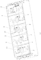
- the present application provides a battery module, which includes: two or more battery cells 1, connecting members 2 and clamping-sampling members 3, wherein the battery cells 1 are disposed in an arrangement, that is, two or more battery cells 1 are arranged side by side.
- Each battery cell 1 is provided with an electrode terminal 11, and the electrode terminals 11 of adjacent battery cells 1 are connected by the connecting member 2;
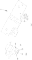
- the clamping-sampling member 3 includes a wire connection portion 37 for fixing a wire harness 4 and a clamping portion, wherein one end of the clamping portion is connected with the wire connection portion 37, and the other end of the clamping portion clamps the connecting member 2.
- the wire connection portion 37 is used to fix the wire harness 4 for information collection, and the clamping portion is used for clamping of the clamping-sampling member 3 on the connecting member 2.
- the clamping portion and the wire connection portion 37 are both conductors for information collection.
- the information collection wire harness 4 obtains voltage information on the connecting member 2 via the wire connection portion 37 and the clamping portion, so as to obtain the voltage situation among the battery cells 1 in the battery module.
- the clamping portion includes a first clamping part 31 and a second clamping part 32 located on two sides of the clamping portion. That is, the clamping portion includes the first clamping part 31 and the second clamping part 32.
- One end of the first clamping part 31 is fixedly connected with one end of the second clamping part 32, while the other end of the first clamping part 31 and the other end of the second clamping part 32 form an opening 33 of the clamping portion, and the one ends of the first clamping part 31 and the second clamping part 32 fixedly connected to each other are connected with the wire connection portion 37.
- the first clamping part 31 is provided with a protrusion 36 on a side surface of the opening 33 facing the second clamping part 32, that is, the first clamping part 31 is provided with a protrusion 36 on a surface facing the second clamping part 32.
- a second clamping part 32 is provided with a protrusion 36 on a side surface of the opening 33 facing the first clamping part 31, that is, the second clamping part 32 is provided with a protrusion 36 on a surface facing the first clamping part 31.
- the sampling installation portion 21 is provided with a connection hole 23, and the protrusion 36 is matched with the connection hole 23.
- the first clamping part 31 and the second clamping part are independently formed.
- the first clamping part 31 is provided with a holding part 34 for holding the second clamping part 32, or, the second clamping part 32 is provided with a holding part 34 for holding the first clamping part 31, wherein the holding part 34 is located at the one ends of the first clamping part 31 and the second clamping part 32 fixedly connected to each other. That is, the other end of the first clamping part 31 and the other end of the second clamping part 32 are connected to each other by the holding part 34.
- first clamping part 31 and the second clamping part 32 are each formed in a sheet-like shape and have the same size.
- the other end of the first clamping part 31 extends in a same direction as the other end of the second clamping part 32, and the opening 33 formed by the first clamping part 31 and the second clamping part 32 is used to fix the clamping portion on the connecting member 2.
- the opening 33 formed between the first clamping part 31 and the second clamping part 32 may be closed when not in use, that is, at least part of the first clamping part 31 and at least part of the second clamping part 32 are attached to each other when the opening is not in use; or, the opening 33 formed between the first clamping part 31 and the second clamping part 32 has a smallest gap value less than a thickness value of the connecting member 2, that is, the smallest distance between the first clamping part 31 and the second clamping part 32 is smaller than or equal to the thickness value of the connecting member 2.
- an operator separates the first clamping portion 31 and the second clamping portion 32 so as to open the opening 33 and clamp the connecting member 2 to the clamping portion.
- the opening 33 formed between the first clamping part 31 and the second clamping part 32 is in a closed state or has a smallest gap value smaller than the thickness value of the connecting member 2, when clamping the connecting member 2 to the clamping portion, the clamping portion can be fixed with the connecting member 2.
- the first clamping part 31 and the second clamping part 32 are integrally formed.
- An integral member of the first clamping part 31 and the second clamping part 32 are bent in a middle portion to form a first clamping part 31 and a second clamping part 32 opposite to each other, that is, the first clamping part 31 and the second clamping part 32 that are integrally formed are connected to each other via a bending part.
- the bending part is provided with a wire connection portion 37 for connecting with the information collection wire harness 4.
- the first clamping part 31 and the second clamping part 32 opposite to each other form an opening 33 of the clamping portion. That is, the first clamping part 31 and the second clamping part 32 connected by the bending part form the opening 33 of the clamping portion.
- the first clamping part 31 and the second clamping part 32 are made of ductile materials to ensure an elasticity of the opening 33 of the clamping portion.
- the connecting member 2 is provided with a sampling installation portion 21, and the clamping portion clamps the sampling installation portion 21.
- the sampling installation portion 21 is arranged at a side position of the connecting member 2. That is, the sampling installation portion 21 is provided on a side of the connecting member 2 facing the wire harness 4.
- the sampling installation portion 21 provided on the connecting member 2, which is formed in a sheet-like shape, is an area recessed towards a battery top cover 12. That is, the sampling installation portion 21 is formed by an indentation of the connecting member 2 towards the battery top cover 12.
- the clamping-sampling member 3 clamps the sampling installation portion 21 of the connecting member 2
- the clamping-sampling member 3 is attached on a top of the battery top cover 12, and the wire harness 4 fixed on the wire connection portion 37 of the clamping-sampling member 3 may also be disposed on the top of the battery top cover 12, so as to prevent the wire harness 4 from being suspended and thus breaking due to vibrations during the use of the battery module.
- the holding part 34 provided on the first clamping part 31 extends outwards respectively from two sides of the first clamping part 31 and thus forms two side wings. That is, the holding part 34 provided on the first clamping part 31 includes two side wings respectively connected to the two sides of the first clamping part 31.
- the side wing is formed in a shape of "L" and includes a first arm and a second arm. The second arm is connected to the first clamping part 31 via the first arm, and the second arms of the two side wings are formed to extend towards each other.
- the two side wings of the first clamping part 31 holds the second clamping part 32 (that is, the second clamping part 32 is located between the two second arms and the first clamping part 31), so as to fix the first clamping part 31 with the second clamping part 32.
- the holding part 34 provided on the second clamping part 32 extends outwards respectively from two sides of the second clamping part 32 and thus forms two side wings. That is, the holding part 34 provided on the second clamping part 32 includes two side wings respectively connected to the two sides of the second clamping part 32.
- the side wing is formed in a shape of "L" and includes a first arm and a second arm.
- the second arm is connected to the second clamping part 32 via the first arm, and the second arms of the two side wings are formed to extend towards each other.
- the two side wings of the second clamping part 32 holds the first clamping part 31 (that is, the first clamping part 31 is located between the two second arms and the second clamping part 32), so as to fix the second clamping part 32 with the first clamping part 31.
- the first clamping part 31 and the second clamping part 32 forms a guide opening 35, which flares outwards, at the end of the opening 33. That is, the ends of the first clamping part 31 and the second clamping part 32 separated from each other, extend away from each other and thus form a guide opening 35.
- the guide opening 35 functions to facilitate positioning of the clamping-sampling member 3 relative to the connecting member 2. After aligning the guide opening 35 of the clamping-sampling member 3 with the connecting member 2, the clamping-sampling member 3 may be pushed towards the connecting member 2 so that the clamping-sampling member 3 clamps the connecting member 2.
- connection holes 23 there are two or more connection holes 23, and there are two or more protrusions 36, which is beneficial for fixing the clamping-sampling member 3 in a direction parallel to the connecting member 2, so as to prevent the clamping-sampling member 3 from rotating in the connection hole 23 of the connecting member 2 and thus affecting the connection strength of the wire harness 4 with the wire connection portion 37.
- the sampling installation portion 21 is further provided with a guide slot 22 extending from an end of the sampling installation portion 21 towards an inside of the connecting member 2, and the protrusion 36 on the first clamping part 31 or the second clamping part 32 may slide along the guide slot 22.
- the guide slot 22 is used to facilitate positioning of the protrusion 36 on the first clamping part 31 or the second clamping part 32, so that the protrusion 36 on the first clamping part 31 or the second clamping part 32 can slide along the guide slot 22 and engage into the connection hole 23.
- connection holes 23 provided on the sampling installation portion 21, and the three connection holes 23 are distributed in a triangular arrangement, that is, the three connection holes 23 are not in the same straight line.
- one of the protrusions 36 on the clamping-sampling member 3 slides along the guide slot 22 until
Landscapes
- Chemical & Material Sciences (AREA)
- Chemical Kinetics & Catalysis (AREA)
- Electrochemistry (AREA)
- General Chemical & Material Sciences (AREA)
- Engineering & Computer Science (AREA)
- Manufacturing & Machinery (AREA)
- Connection Of Batteries Or Terminals (AREA)
- Battery Mounting, Suspending (AREA)
- Clamps And Clips (AREA)
Claims (7)
- Module de batterie comprenant :deux ou plus cellules de batterie (1), chacun comprenant une borne d'électrode (11) ;un élément de connexion (2), dans lequel les bornes d'électrode (11) des cellules de batterie adjacents (1) sont connectées par l'élément de connexion (2) ; etun élément de pinçage-échantillonnage (3), comprenant une portion de connexion de fil (37) pour fixer un faisceau de fils (4) et une portion de pinçage, dans lequel l'une extrémité de la portion de pinçage est connectée à la portion de connexion de fil (37) et l'autre l'extrémité de la portion de pinçage pince l'élément de connexion (2),la portion de pinçage comprend une première portion de pinçage (31) et une seconde portion de pinçage (32), une extrémité de la première portion de pinçage (31) est connectée de manière fixe à une extrémité de la seconde portion de pinçage (32), tandis que l'autre extrémité de la première portion de pinçage (31) et l'autre extrémité de la seconde portion de pinçage (32) délimitent une ouverture (33) de la portion de pinçage, et l'une d'extrémité de la première portion de pinçage (31) et l'une d'extrémité de la seconde portion de pinçage (32) connectées de manière fixe l'une à l'autre sont connectées à la portion de connexion de fil (37),la première portion de pinçage (31) est pourvue d'une saillie (36) sur une surface latérale de l'ouverture (33) faisant face à la seconde portion de pinçage (32), ou la seconde portion de pinçage (32) est pourvue d'une saillie (36) sur une surface latérale de l'ouverture (33) faisant face à la première portion de pinçage (31) ;une portion d'installation d'échantillonnage (21) est pourvue d'un trou de connexion (23) et la saillie (36) est adaptée au trou de connexion (23),caractérisé en ce que,la première portion de pinçage (31) et la seconde portion de pinçage (32) sont formées de manière indépendante,la première portion de pinçage (31) est pourvue d'une portion de maintien (34) pour maintenir la seconde portion de pinçage (32), ou la seconde portion de pinçage (32) est pourvue d'une portion de maintien (34) pour maintenir la première portion de pinçage (31),dans lequel la portion de maintien (34) est disposée à l'une extrémité de la première portion de pinçage (31) et à l'une extrémité de la seconde portion de pinçage (32) connectées manière fixe l'une à l'autre.
- Module de batterie selon la revendication 1, caractérisé en ce que l'élément de connexion (2) est pourvu d'une portion d'installation d'échantillonnage (21), et la portion de pinçage pince la portion d'installation d'échantillonnage (21).
- Module de batterie selon la revendication 2, caractérisé en ce que la portion d'installation d'échantillonnage (21) est prévue sur un côté de l'élément de connexion (2) faisant face au faisceau de fils (4).
- Module de batterie selon la revendication 1, caractérisé en ce que la portion de maintien (34) comprend deux ailes latérales connectées respectivement à deux côtés de la première portion de pinçage (31) ou de la seconde portion de pinçage (32), chaque aile latérale se présente une forme « L » et comprend un premier bras et un second bras, le second bras est connecté à la première portion de pinçage (31) ou à la seconde portion de pinçage (32) par l'intermédiaire du premier bras, et les secondes bras des deux ailes latérales sont formées en s'étendant l'une vers l'autre.
- Module de batterie selon la revendication 1, caractérisé en ce que, deux ou plusieurs trous de connexion (23) sont prévus.
- Module de batterie selon la revendication 1, caractérisé en ce que la portion d'installation d'échantillonnage (21) est pourvue en outre d'une fente de guidage (22) s'étendant depuis une extrémité de la portion d'installation d'échantillonnage (21) vers l'intérieur de l'élément de connexion (2), de sorte que la saillie (36) sur la première portion de pinçage (31) ou sur la seconde portion de pinçage (32) puisse coulisser le long de la fente de guidage (22).
- Module de batterie selon la revendication 1, caractérisé en ce que la portion de connexion de fil (37) présente une section transversale en forme U, de sorte que le faisceau de fils (4) soit installé à l'intérieur de la portion de connexion de fil (37).
Applications Claiming Priority (3)
| Application Number | Priority Date | Filing Date | Title |
|---|---|---|---|
| CN201822267068.2U CN209447908U (zh) | 2018-12-29 | 2018-12-29 | 一种电池模块 |
| EP19870046.0A EP3699979B1 (fr) | 2018-12-29 | 2019-11-26 | Module de batterie |
| PCT/CN2019/120880 WO2020134799A1 (fr) | 2018-12-29 | 2019-11-26 | Module de batterie |
Related Parent Applications (2)
| Application Number | Title | Priority Date | Filing Date |
|---|---|---|---|
| EP19870046.0A Division EP3699979B1 (fr) | 2018-12-29 | 2019-11-26 | Module de batterie |
| EP19870046.0A Division-Into EP3699979B1 (fr) | 2018-12-29 | 2019-11-26 | Module de batterie |
Publications (2)
| Publication Number | Publication Date |
|---|---|
| EP3944397A1 EP3944397A1 (fr) | 2022-01-26 |
| EP3944397B1 true EP3944397B1 (fr) | 2022-12-21 |
Family
ID=68016767
Family Applications (3)
| Application Number | Title | Priority Date | Filing Date |
|---|---|---|---|
| EP19870046.0A Active EP3699979B1 (fr) | 2018-12-29 | 2019-11-26 | Module de batterie |
| EP21193753.7A Active EP3944398B1 (fr) | 2018-12-29 | 2019-11-26 | Module de batterie |
| EP21193751.1A Active EP3944397B1 (fr) | 2018-12-29 | 2019-11-26 | Module de batterie |
Family Applications Before (2)
| Application Number | Title | Priority Date | Filing Date |
|---|---|---|---|
| EP19870046.0A Active EP3699979B1 (fr) | 2018-12-29 | 2019-11-26 | Module de batterie |
| EP21193753.7A Active EP3944398B1 (fr) | 2018-12-29 | 2019-11-26 | Module de batterie |
Country Status (5)
| Country | Link |
|---|---|
| US (2) | US11641046B2 (fr) |
| EP (3) | EP3699979B1 (fr) |
| CN (1) | CN209447908U (fr) |
| ES (1) | ES2899629T3 (fr) |
| WO (1) | WO2020134799A1 (fr) |
Families Citing this family (21)
| Publication number | Priority date | Publication date | Assignee | Title |
|---|---|---|---|---|
| CN209447908U (zh) | 2018-12-29 | 2019-09-27 | 宁德时代新能源科技股份有限公司 | 一种电池模块 |
| CN112332036B (zh) * | 2020-04-03 | 2023-04-07 | 宁德时代新能源科技股份有限公司 | 电池模块、电池组、装置及失效处理方法 |
| CN111710822A (zh) * | 2020-06-19 | 2020-09-25 | 中航锂电(洛阳)有限公司 | 一种电池模组 |
| CN111916647B (zh) * | 2020-08-14 | 2025-09-16 | 合肥国轩高科动力能源有限公司 | 软包动力电池模组 |
| EP4123842A1 (fr) * | 2021-07-23 | 2023-01-25 | A. Raymond et Cie | Système de contact et jeu de batteries le comportant |
| EP4123818A1 (fr) * | 2021-07-23 | 2023-01-25 | A. Raymond et Cie | Unité de batterie, système et procédé d'assemblage du système |
| CN116742289A (zh) * | 2022-03-02 | 2023-09-12 | 宁德时代新能源科技股份有限公司 | 电连接器、采样组件、电池和用电设备 |
| US12506215B2 (en) | 2022-03-23 | 2025-12-23 | Ford Global Technologies, Llc | Enclosure cover attachment configurations for traction battery packs with cell-to-pack battery systems |
| US12374750B2 (en) | 2022-03-23 | 2025-07-29 | Ford Global Technologies, Llc | Traction battery pack assembling method |
| US12633564B2 (en) | 2022-03-23 | 2026-05-19 | Ford Global Technologies, Llc | Battery lift and transfer solutions for assembling traction battery packs |
| US12275298B2 (en) | 2022-03-23 | 2025-04-15 | Ford Global Technologies, Llc | Traction battery packs with cell-to-pack battery systems housed within irregularly shaped enclosures |
| US12479327B2 (en) | 2022-03-23 | 2025-11-25 | Ford Global Technologies, Llc | Traction battery pack cell stack removal method and battery pack assembly |
| US12525637B2 (en) | 2022-03-23 | 2026-01-13 | Ford Global Technologies, Llc | Traction battery pack assembling method |
| US12424695B2 (en) | 2022-03-23 | 2025-09-23 | Ford Global Technologies, Llc | Retention assemblies for traction battery packs with cell-to-pack battery systems |
| US12230826B2 (en) | 2022-03-23 | 2025-02-18 | Ford Global Technologies, Llc | Methods for assembling traction battery packs |
| US12651799B2 (en) | 2022-03-23 | 2026-06-09 | Ford Global Technologies, Llc | Traction battery pack assembling method |
| US12567642B2 (en) | 2022-03-23 | 2026-03-03 | Ford Global Technologies, Llc | Shim systems for traction battery packs |
| US12603373B2 (en) | 2022-03-23 | 2026-04-14 | Ford Global Technologies, Llc | Traction battery pack assembling method |
| CN116845448A (zh) * | 2022-03-24 | 2023-10-03 | 良丰能源科技有限公司 | 夹持装置及电池装置 |
| DE102022114957A1 (de) | 2022-06-14 | 2023-12-14 | Te Connectivity Germany Gmbh | Sensorkontaktierung, Zellverbinderterminal sowie Zellverbinderblech |
| CN121076422A (zh) * | 2025-11-05 | 2025-12-05 | 宁德时代新能源科技股份有限公司 | 电池装置及用电设备 |
Family Cites Families (13)
| Publication number | Priority date | Publication date | Assignee | Title |
|---|---|---|---|---|
| JP5285997B2 (ja) * | 2008-08-27 | 2013-09-11 | 矢崎総業株式会社 | 電源装置 |
| US7967648B2 (en) * | 2008-10-15 | 2011-06-28 | Byrne Norman R | Terminal |
| JP5443097B2 (ja) * | 2009-08-18 | 2014-03-19 | 矢崎総業株式会社 | 電源装置 |
| JP2011258412A (ja) | 2010-06-09 | 2011-12-22 | Auto Network Gijutsu Kenkyusho:Kk | 電池接続プレート |
| DE102012213673A1 (de) * | 2012-08-02 | 2014-02-06 | Robert Bosch Gmbh | Batteriemodul sowie Batterie und Kraftfahrzeug umfassend ein solches |
| EP3262719B1 (fr) * | 2015-02-27 | 2020-08-26 | Byrne, Norman R. | Réceptacle de contact électrique pour barres omnibus et bornes de lame |
| CN105914506B (zh) | 2016-04-14 | 2018-05-04 | 安徽江淮汽车集团股份有限公司 | 一种线束母端子及其卡接结构 |
| CN206098597U (zh) | 2016-09-26 | 2017-04-12 | 常州普莱德新能源电池科技有限公司 | 一种动力电池系统电压和温度信号采集端子及系统 |
| CN206684255U (zh) | 2017-03-17 | 2017-11-28 | 成都雅骏新能源汽车科技股份有限公司 | 电池包单体采样线束来料检测系统 |
| US10193191B2 (en) * | 2017-06-09 | 2019-01-29 | GM Global Technology Operations LLC | Electrical system with battery module and cover assembly providing built-in circuit protection |
| CN109273650B (zh) * | 2017-07-18 | 2021-06-04 | 宁德时代新能源科技股份有限公司 | 电池模组 |
| CN207818732U (zh) | 2018-03-08 | 2018-09-04 | 宁德时代新能源科技股份有限公司 | 电池模组 |
| CN209447908U (zh) * | 2018-12-29 | 2019-09-27 | 宁德时代新能源科技股份有限公司 | 一种电池模块 |
-
2018
- 2018-12-29 CN CN201822267068.2U patent/CN209447908U/zh active Active
-
2019
- 2019-11-26 EP EP19870046.0A patent/EP3699979B1/fr active Active
- 2019-11-26 US US16/760,166 patent/US11641046B2/en active Active
- 2019-11-26 EP EP21193753.7A patent/EP3944398B1/fr active Active
- 2019-11-26 EP EP21193751.1A patent/EP3944397B1/fr active Active
- 2019-11-26 ES ES19870046T patent/ES2899629T3/es active Active
- 2019-11-26 WO PCT/CN2019/120880 patent/WO2020134799A1/fr not_active Ceased
-
2021
- 2021-01-14 US US17/148,601 patent/US11050125B1/en active Active
Also Published As
| Publication number | Publication date |
|---|---|
| EP3699979A4 (fr) | 2020-12-16 |
| US20210218117A1 (en) | 2021-07-15 |
| US11641046B2 (en) | 2023-05-02 |
| US11050125B1 (en) | 2021-06-29 |
| EP3944398A1 (fr) | 2022-01-26 |
| EP3699979B1 (fr) | 2021-11-03 |
| ES2899629T3 (es) | 2022-03-14 |
| WO2020134799A1 (fr) | 2020-07-02 |
| EP3944397A1 (fr) | 2022-01-26 |
| EP3944398B1 (fr) | 2022-10-19 |
| EP3699979A1 (fr) | 2020-08-26 |
| CN209447908U (zh) | 2019-09-27 |
Similar Documents
| Publication | Publication Date | Title |
|---|---|---|
| EP3944398B1 (fr) | Module de batterie | |
| US20210066700A1 (en) | Single-cell battery, battery module, power battery and electric vehicle | |
| EP4027446A3 (fr) | Barre omnibus et module de batterie la comprenant | |
| EP3312902A1 (fr) | Batterie assemblée | |
| CN104253252A (zh) | 电池模块 | |
| CN106797010B (zh) | 布线模块以及布线模块的制造方法 | |
| CN204966568U (zh) | 动力电池模组 | |
| EP3082177A1 (fr) | Module de cellule secondaire | |
| EP3490024B1 (fr) | Bloc batterie | |
| CN105870366A (zh) | 动力电池顶盖及动力电池 | |
| JP4939643B1 (ja) | 電池モジュール | |
| CN105845850A (zh) | 动力电池顶盖及其动力电池 | |
| EP4050633A1 (fr) | Dispositif de stockage électrique | |
| CN208111556U (zh) | 电池采样组件及电池箱 | |
| CN104685666A (zh) | 电池模块以及包括这种电池模块的电池和机动车 | |
| CN106100569B (zh) | 端子箱及太阳能电池模组 | |
| CN215418447U (zh) | 电池模组及电池 | |
| CN214848960U (zh) | 电池模组及二次电池 | |
| CN205666262U (zh) | 动力电池顶盖及动力电池 | |
| CN220400838U (zh) | 连接组件、电池包及用电设备 | |
| EP4478523A1 (fr) | Dispositif de détection de tension et module de batterie | |
| CN213342145U (zh) | 一种分体式接线盒及光伏组件 | |
| CN219477007U (zh) | 采集端子及采集端子组件 | |
| CN206639856U (zh) | 用于电池包的汇流排和电池包 | |
| CN224067838U (zh) | 一种新型分体式ccs采集模组及储能电池柜 |
Legal Events
| Date | Code | Title | Description |
|---|---|---|---|
| PUAI | Public reference made under article 153(3) epc to a published international application that has entered the european phase |
Free format text: ORIGINAL CODE: 0009012 |
|
| STAA | Information on the status of an ep patent application or granted ep patent |
Free format text: STATUS: THE APPLICATION HAS BEEN PUBLISHED |
|
| AC | Divisional application: reference to earlier application |
Ref document number: 3699979 Country of ref document: EP Kind code of ref document: P |
|
| AK | Designated contracting states |
Kind code of ref document: A1 Designated state(s): AL AT BE BG CH CY CZ DE DK EE ES FI FR GB GR HR HU IE IS IT LI LT LU LV MC MK MT NL NO PL PT RO RS SE SI SK SM TR |
|
| STAA | Information on the status of an ep patent application or granted ep patent |
Free format text: STATUS: REQUEST FOR EXAMINATION WAS MADE |
|
| 17P | Request for examination filed |
Effective date: 20220318 |
|
| RBV | Designated contracting states (corrected) |
Designated state(s): AL AT BE BG CH CY CZ DE DK EE ES FI FR GB GR HR HU IE IS IT LI LT LU LV MC MK MT NL NO PL PT RO RS SE SI SK SM TR |
|
| GRAP | Despatch of communication of intention to grant a patent |
Free format text: ORIGINAL CODE: EPIDOSNIGR1 |
|
| STAA | Information on the status of an ep patent application or granted ep patent |
Free format text: STATUS: GRANT OF PATENT IS INTENDED |
|
| INTG | Intention to grant announced |
Effective date: 20220713 |
|
| GRAS | Grant fee paid |
Free format text: ORIGINAL CODE: EPIDOSNIGR3 |
|
| GRAA | (expected) grant |
Free format text: ORIGINAL CODE: 0009210 |
|
| STAA | Information on the status of an ep patent application or granted ep patent |
Free format text: STATUS: THE PATENT HAS BEEN GRANTED |
|
| RAP3 | Party data changed (applicant data changed or rights of an application transferred) |
Owner name: CONTEMPORARY AMPEREX TECHNOLOGY CO., LIMITED |
|
| AC | Divisional application: reference to earlier application |
Ref document number: 3699979 Country of ref document: EP Kind code of ref document: P |
|
| AK | Designated contracting states |
Kind code of ref document: B1 Designated state(s): AL AT BE BG CH CY CZ DE DK EE ES FI FR GB GR HR HU IE IS IT LI LT LU LV MC MK MT NL NO PL PT RO RS SE SI SK SM TR |
|
| REG | Reference to a national code |
Ref country code: GB Ref legal event code: FG4D |
|
| REG | Reference to a national code |
Ref country code: DE Ref legal event code: R096 Ref document number: 602019023557 Country of ref document: DE |
|
| REG | Reference to a national code |
Ref country code: CH Ref legal event code: EP |
|
| REG | Reference to a national code |
Ref country code: AT Ref legal event code: REF Ref document number: 1539595 Country of ref document: AT Kind code of ref document: T Effective date: 20230115 |
|
| REG | Reference to a national code |
Ref country code: IE Ref legal event code: FG4D |
|
| REG | Reference to a national code |
Ref country code: NO Ref legal event code: T2 Effective date: 20221221 |
|
| REG | Reference to a national code |
Ref country code: LT Ref legal event code: MG9D |
|
| REG | Reference to a national code |
Ref country code: NL Ref legal event code: MP Effective date: 20221221 |
|
| PG25 | Lapsed in a contracting state [announced via postgrant information from national office to epo] |
Ref country code: SE Free format text: LAPSE BECAUSE OF FAILURE TO SUBMIT A TRANSLATION OF THE DESCRIPTION OR TO PAY THE FEE WITHIN THE PRESCRIBED TIME-LIMIT Effective date: 20221221 Ref country code: LT Free format text: LAPSE BECAUSE OF FAILURE TO SUBMIT A TRANSLATION OF THE DESCRIPTION OR TO PAY THE FEE WITHIN THE PRESCRIBED TIME-LIMIT Effective date: 20221221 Ref country code: FI Free format text: LAPSE BECAUSE OF FAILURE TO SUBMIT A TRANSLATION OF THE DESCRIPTION OR TO PAY THE FEE WITHIN THE PRESCRIBED TIME-LIMIT Effective date: 20221221 |
|
| REG | Reference to a national code |
Ref country code: AT Ref legal event code: MK05 Ref document number: 1539595 Country of ref document: AT Kind code of ref document: T Effective date: 20221221 |
|
| PG25 | Lapsed in a contracting state [announced via postgrant information from national office to epo] |
Ref country code: RS Free format text: LAPSE BECAUSE OF FAILURE TO SUBMIT A TRANSLATION OF THE DESCRIPTION OR TO PAY THE FEE WITHIN THE PRESCRIBED TIME-LIMIT Effective date: 20221221 Ref country code: LV Free format text: LAPSE BECAUSE OF FAILURE TO SUBMIT A TRANSLATION OF THE DESCRIPTION OR TO PAY THE FEE WITHIN THE PRESCRIBED TIME-LIMIT Effective date: 20221221 Ref country code: HR Free format text: LAPSE BECAUSE OF FAILURE TO SUBMIT A TRANSLATION OF THE DESCRIPTION OR TO PAY THE FEE WITHIN THE PRESCRIBED TIME-LIMIT Effective date: 20221221 Ref country code: GR Free format text: LAPSE BECAUSE OF FAILURE TO SUBMIT A TRANSLATION OF THE DESCRIPTION OR TO PAY THE FEE WITHIN THE PRESCRIBED TIME-LIMIT Effective date: 20230322 |
|
| P01 | Opt-out of the competence of the unified patent court (upc) registered |
Effective date: 20230516 |
|
| PG25 | Lapsed in a contracting state [announced via postgrant information from national office to epo] |
Ref country code: NL Free format text: LAPSE BECAUSE OF FAILURE TO SUBMIT A TRANSLATION OF THE DESCRIPTION OR TO PAY THE FEE WITHIN THE PRESCRIBED TIME-LIMIT Effective date: 20221221 |
|
| PG25 | Lapsed in a contracting state [announced via postgrant information from national office to epo] |
Ref country code: SM Free format text: LAPSE BECAUSE OF FAILURE TO SUBMIT A TRANSLATION OF THE DESCRIPTION OR TO PAY THE FEE WITHIN THE PRESCRIBED TIME-LIMIT Effective date: 20221221 Ref country code: RO Free format text: LAPSE BECAUSE OF FAILURE TO SUBMIT A TRANSLATION OF THE DESCRIPTION OR TO PAY THE FEE WITHIN THE PRESCRIBED TIME-LIMIT Effective date: 20221221 Ref country code: PT Free format text: LAPSE BECAUSE OF FAILURE TO SUBMIT A TRANSLATION OF THE DESCRIPTION OR TO PAY THE FEE WITHIN THE PRESCRIBED TIME-LIMIT Effective date: 20230421 Ref country code: ES Free format text: LAPSE BECAUSE OF FAILURE TO SUBMIT A TRANSLATION OF THE DESCRIPTION OR TO PAY THE FEE WITHIN THE PRESCRIBED TIME-LIMIT Effective date: 20221221 Ref country code: EE Free format text: LAPSE BECAUSE OF FAILURE TO SUBMIT A TRANSLATION OF THE DESCRIPTION OR TO PAY THE FEE WITHIN THE PRESCRIBED TIME-LIMIT Effective date: 20221221 Ref country code: CZ Free format text: LAPSE BECAUSE OF FAILURE TO SUBMIT A TRANSLATION OF THE DESCRIPTION OR TO PAY THE FEE WITHIN THE PRESCRIBED TIME-LIMIT Effective date: 20221221 Ref country code: AT Free format text: LAPSE BECAUSE OF FAILURE TO SUBMIT A TRANSLATION OF THE DESCRIPTION OR TO PAY THE FEE WITHIN THE PRESCRIBED TIME-LIMIT Effective date: 20221221 |
|
| PG25 | Lapsed in a contracting state [announced via postgrant information from national office to epo] |
Ref country code: SK Free format text: LAPSE BECAUSE OF FAILURE TO SUBMIT A TRANSLATION OF THE DESCRIPTION OR TO PAY THE FEE WITHIN THE PRESCRIBED TIME-LIMIT Effective date: 20221221 Ref country code: PL Free format text: LAPSE BECAUSE OF FAILURE TO SUBMIT A TRANSLATION OF THE DESCRIPTION OR TO PAY THE FEE WITHIN THE PRESCRIBED TIME-LIMIT Effective date: 20221221 Ref country code: IS Free format text: LAPSE BECAUSE OF FAILURE TO SUBMIT A TRANSLATION OF THE DESCRIPTION OR TO PAY THE FEE WITHIN THE PRESCRIBED TIME-LIMIT Effective date: 20230421 Ref country code: AL Free format text: LAPSE BECAUSE OF FAILURE TO SUBMIT A TRANSLATION OF THE DESCRIPTION OR TO PAY THE FEE WITHIN THE PRESCRIBED TIME-LIMIT Effective date: 20221221 |
|
| REG | Reference to a national code |
Ref country code: DE Ref legal event code: R097 Ref document number: 602019023557 Country of ref document: DE |
|
| PLBE | No opposition filed within time limit |
Free format text: ORIGINAL CODE: 0009261 |
|
| STAA | Information on the status of an ep patent application or granted ep patent |
Free format text: STATUS: NO OPPOSITION FILED WITHIN TIME LIMIT |
|
| PG25 | Lapsed in a contracting state [announced via postgrant information from national office to epo] |
Ref country code: DK Free format text: LAPSE BECAUSE OF FAILURE TO SUBMIT A TRANSLATION OF THE DESCRIPTION OR TO PAY THE FEE WITHIN THE PRESCRIBED TIME-LIMIT Effective date: 20221221 |
|
| 26N | No opposition filed |
Effective date: 20230922 |
|
| PG25 | Lapsed in a contracting state [announced via postgrant information from national office to epo] |
Ref country code: SI Free format text: LAPSE BECAUSE OF FAILURE TO SUBMIT A TRANSLATION OF THE DESCRIPTION OR TO PAY THE FEE WITHIN THE PRESCRIBED TIME-LIMIT Effective date: 20221221 |
|
| PG25 | Lapsed in a contracting state [announced via postgrant information from national office to epo] |
Ref country code: IT Free format text: LAPSE BECAUSE OF FAILURE TO SUBMIT A TRANSLATION OF THE DESCRIPTION OR TO PAY THE FEE WITHIN THE PRESCRIBED TIME-LIMIT Effective date: 20221221 |
|
| REG | Reference to a national code |
Ref country code: CH Ref legal event code: PL |
|
| PG25 | Lapsed in a contracting state [announced via postgrant information from national office to epo] |
Ref country code: MC Free format text: LAPSE BECAUSE OF FAILURE TO SUBMIT A TRANSLATION OF THE DESCRIPTION OR TO PAY THE FEE WITHIN THE PRESCRIBED TIME-LIMIT Effective date: 20221221 |
|
| PG25 | Lapsed in a contracting state [announced via postgrant information from national office to epo] |
Ref country code: LU Free format text: LAPSE BECAUSE OF NON-PAYMENT OF DUE FEES Effective date: 20231126 |
|
| PG25 | Lapsed in a contracting state [announced via postgrant information from national office to epo] |
Ref country code: CH Free format text: LAPSE BECAUSE OF NON-PAYMENT OF DUE FEES Effective date: 20231130 |
|
| PG25 | Lapsed in a contracting state [announced via postgrant information from national office to epo] |
Ref country code: MC Free format text: LAPSE BECAUSE OF FAILURE TO SUBMIT A TRANSLATION OF THE DESCRIPTION OR TO PAY THE FEE WITHIN THE PRESCRIBED TIME-LIMIT Effective date: 20221221 Ref country code: LU Free format text: LAPSE BECAUSE OF NON-PAYMENT OF DUE FEES Effective date: 20231126 Ref country code: CH Free format text: LAPSE BECAUSE OF NON-PAYMENT OF DUE FEES Effective date: 20231130 |
|
| REG | Reference to a national code |
Ref country code: BE Ref legal event code: MM Effective date: 20231130 |
|
| REG | Reference to a national code |
Ref country code: DE Ref legal event code: R081 Ref document number: 602019023557 Country of ref document: DE Owner name: CONTEMPORARY AMPEREX TECHNOLOGY (HONG KONG) LI, HK Free format text: FORMER OWNER: CONTEMPORARY AMPEREX TECHNOLOGY CO., LIMITED, NINGDE CITY, FUJIAN, CN |
|
| REG | Reference to a national code |
Ref country code: IE Ref legal event code: MM4A |
|
| REG | Reference to a national code |
Ref country code: GB Ref legal event code: 732E Free format text: REGISTERED BETWEEN 20240829 AND 20240904 |
|
| PG25 | Lapsed in a contracting state [announced via postgrant information from national office to epo] |
Ref country code: IE Free format text: LAPSE BECAUSE OF NON-PAYMENT OF DUE FEES Effective date: 20231126 |
|
| PG25 | Lapsed in a contracting state [announced via postgrant information from national office to epo] |
Ref country code: BE Free format text: LAPSE BECAUSE OF NON-PAYMENT OF DUE FEES Effective date: 20231130 |
|
| PG25 | Lapsed in a contracting state [announced via postgrant information from national office to epo] |
Ref country code: IE Free format text: LAPSE BECAUSE OF NON-PAYMENT OF DUE FEES Effective date: 20231126 Ref country code: BE Free format text: LAPSE BECAUSE OF NON-PAYMENT OF DUE FEES Effective date: 20231130 |
|
| PG25 | Lapsed in a contracting state [announced via postgrant information from national office to epo] |
Ref country code: BG Free format text: LAPSE BECAUSE OF FAILURE TO SUBMIT A TRANSLATION OF THE DESCRIPTION OR TO PAY THE FEE WITHIN THE PRESCRIBED TIME-LIMIT Effective date: 20221221 |
|
| PG25 | Lapsed in a contracting state [announced via postgrant information from national office to epo] |
Ref country code: BG Free format text: LAPSE BECAUSE OF FAILURE TO SUBMIT A TRANSLATION OF THE DESCRIPTION OR TO PAY THE FEE WITHIN THE PRESCRIBED TIME-LIMIT Effective date: 20221221 |
|
| PG25 | Lapsed in a contracting state [announced via postgrant information from national office to epo] |
Ref country code: CY Free format text: LAPSE BECAUSE OF FAILURE TO SUBMIT A TRANSLATION OF THE DESCRIPTION OR TO PAY THE FEE WITHIN THE PRESCRIBED TIME-LIMIT; INVALID AB INITIO Effective date: 20191126 |
|
| PG25 | Lapsed in a contracting state [announced via postgrant information from national office to epo] |
Ref country code: HU Free format text: LAPSE BECAUSE OF FAILURE TO SUBMIT A TRANSLATION OF THE DESCRIPTION OR TO PAY THE FEE WITHIN THE PRESCRIBED TIME-LIMIT; INVALID AB INITIO Effective date: 20191126 |
|
| PGFP | Annual fee paid to national office [announced via postgrant information from national office to epo] |
Ref country code: FR Payment date: 20250930 Year of fee payment: 7 |
|
| PG25 | Lapsed in a contracting state [announced via postgrant information from national office to epo] |
Ref country code: TR Free format text: LAPSE BECAUSE OF FAILURE TO SUBMIT A TRANSLATION OF THE DESCRIPTION OR TO PAY THE FEE WITHIN THE PRESCRIBED TIME-LIMIT Effective date: 20221221 |
|
| PGFP | Annual fee paid to national office [announced via postgrant information from national office to epo] |
Ref country code: DE Payment date: 20250930 Year of fee payment: 7 |
|
| PGFP | Annual fee paid to national office [announced via postgrant information from national office to epo] |
Ref country code: GB Payment date: 20251001 Year of fee payment: 7 |
|
| PGFP | Annual fee paid to national office [announced via postgrant information from national office to epo] |
Ref country code: NO Payment date: 20251113 Year of fee payment: 7 |