EP3312902A1 - Batterie assemblée - Google Patents
Batterie assemblée Download PDFInfo
- Publication number
- EP3312902A1 EP3312902A1 EP16811366.0A EP16811366A EP3312902A1 EP 3312902 A1 EP3312902 A1 EP 3312902A1 EP 16811366 A EP16811366 A EP 16811366A EP 3312902 A1 EP3312902 A1 EP 3312902A1
- Authority
- EP
- European Patent Office
- Prior art keywords
- circuit board
- insulation cover
- case
- assembled battery
- bus bar
- Prior art date
- Legal status (The legal status is an assumption and is not a legal conclusion. Google has not performed a legal analysis and makes no representation as to the accuracy of the status listed.)
- Granted
Links
Images


Classifications
-
- H—ELECTRICITY
- H01—ELECTRIC ELEMENTS
- H01M—PROCESSES OR MEANS, e.g. BATTERIES, FOR THE DIRECT CONVERSION OF CHEMICAL ENERGY INTO ELECTRICAL ENERGY
- H01M10/00—Secondary cells; Manufacture thereof
- H01M10/42—Methods or arrangements for servicing or maintenance of secondary cells or secondary half-cells
- H01M10/48—Accumulators combined with arrangements for measuring, testing or indicating the condition of cells, e.g. the level or density of the electrolyte
-
- H—ELECTRICITY
- H01—ELECTRIC ELEMENTS
- H01M—PROCESSES OR MEANS, e.g. BATTERIES, FOR THE DIRECT CONVERSION OF CHEMICAL ENERGY INTO ELECTRICAL ENERGY
- H01M10/00—Secondary cells; Manufacture thereof
- H01M10/42—Methods or arrangements for servicing or maintenance of secondary cells or secondary half-cells
- H01M10/425—Structural combination with electronic components, e.g. electronic circuits integrated to the outside of the casing
-
- H—ELECTRICITY
- H01—ELECTRIC ELEMENTS
- H01M—PROCESSES OR MEANS, e.g. BATTERIES, FOR THE DIRECT CONVERSION OF CHEMICAL ENERGY INTO ELECTRICAL ENERGY
- H01M10/00—Secondary cells; Manufacture thereof
- H01M10/42—Methods or arrangements for servicing or maintenance of secondary cells or secondary half-cells
- H01M10/44—Methods for charging or discharging
-
- H—ELECTRICITY
- H01—ELECTRIC ELEMENTS
- H01M—PROCESSES OR MEANS, e.g. BATTERIES, FOR THE DIRECT CONVERSION OF CHEMICAL ENERGY INTO ELECTRICAL ENERGY
- H01M10/00—Secondary cells; Manufacture thereof
- H01M10/42—Methods or arrangements for servicing or maintenance of secondary cells or secondary half-cells
- H01M10/48—Accumulators combined with arrangements for measuring, testing or indicating the condition of cells, e.g. the level or density of the electrolyte
- H01M10/482—Accumulators combined with arrangements for measuring, testing or indicating the condition of cells, e.g. the level or density of the electrolyte for several batteries or cells simultaneously or sequentially
-
- H—ELECTRICITY
- H01—ELECTRIC ELEMENTS
- H01M—PROCESSES OR MEANS, e.g. BATTERIES, FOR THE DIRECT CONVERSION OF CHEMICAL ENERGY INTO ELECTRICAL ENERGY
- H01M50/00—Constructional details or processes of manufacture of the non-active parts of electrochemical cells other than fuel cells, e.g. hybrid cells
- H01M50/20—Mountings; Secondary casings or frames; Racks, modules or packs; Suspension devices; Shock absorbers; Transport or carrying devices; Holders
- H01M50/204—Racks, modules or packs for multiple batteries or multiple cells
- H01M50/207—Racks, modules or packs for multiple batteries or multiple cells characterised by their shape
- H01M50/209—Racks, modules or packs for multiple batteries or multiple cells characterised by their shape adapted for prismatic or rectangular cells
-
- H—ELECTRICITY
- H01—ELECTRIC ELEMENTS
- H01M—PROCESSES OR MEANS, e.g. BATTERIES, FOR THE DIRECT CONVERSION OF CHEMICAL ENERGY INTO ELECTRICAL ENERGY
- H01M50/00—Constructional details or processes of manufacture of the non-active parts of electrochemical cells other than fuel cells, e.g. hybrid cells
- H01M50/20—Mountings; Secondary casings or frames; Racks, modules or packs; Suspension devices; Shock absorbers; Transport or carrying devices; Holders
- H01M50/284—Mountings; Secondary casings or frames; Racks, modules or packs; Suspension devices; Shock absorbers; Transport or carrying devices; Holders with incorporated circuit boards, e.g. printed circuit boards [PCB]
-
- H—ELECTRICITY
- H01—ELECTRIC ELEMENTS
- H01M—PROCESSES OR MEANS, e.g. BATTERIES, FOR THE DIRECT CONVERSION OF CHEMICAL ENERGY INTO ELECTRICAL ENERGY
- H01M50/00—Constructional details or processes of manufacture of the non-active parts of electrochemical cells other than fuel cells, e.g. hybrid cells
- H01M50/50—Current conducting connections for cells or batteries
- H01M50/502—Interconnectors for connecting terminals of adjacent batteries; Interconnectors for connecting cells outside a battery casing
- H01M50/503—Interconnectors for connecting terminals of adjacent batteries; Interconnectors for connecting cells outside a battery casing characterised by the shape of the interconnectors
-
- H—ELECTRICITY
- H01—ELECTRIC ELEMENTS
- H01M—PROCESSES OR MEANS, e.g. BATTERIES, FOR THE DIRECT CONVERSION OF CHEMICAL ENERGY INTO ELECTRICAL ENERGY
- H01M50/00—Constructional details or processes of manufacture of the non-active parts of electrochemical cells other than fuel cells, e.g. hybrid cells
- H01M50/50—Current conducting connections for cells or batteries
- H01M50/502—Interconnectors for connecting terminals of adjacent batteries; Interconnectors for connecting cells outside a battery casing
- H01M50/519—Interconnectors for connecting terminals of adjacent batteries; Interconnectors for connecting cells outside a battery casing comprising printed circuit boards [PCB]
-
- H—ELECTRICITY
- H01—ELECTRIC ELEMENTS
- H01M—PROCESSES OR MEANS, e.g. BATTERIES, FOR THE DIRECT CONVERSION OF CHEMICAL ENERGY INTO ELECTRICAL ENERGY
- H01M10/00—Secondary cells; Manufacture thereof
- H01M10/42—Methods or arrangements for servicing or maintenance of secondary cells or secondary half-cells
- H01M10/425—Structural combination with electronic components, e.g. electronic circuits integrated to the outside of the casing
- H01M2010/4271—Battery management systems including electronic circuits, e.g. control of current or voltage to keep battery in healthy state, cell balancing
-
- H—ELECTRICITY
- H01—ELECTRIC ELEMENTS
- H01M—PROCESSES OR MEANS, e.g. BATTERIES, FOR THE DIRECT CONVERSION OF CHEMICAL ENERGY INTO ELECTRICAL ENERGY
- H01M50/00—Constructional details or processes of manufacture of the non-active parts of electrochemical cells other than fuel cells, e.g. hybrid cells
- H01M50/50—Current conducting connections for cells or batteries
- H01M50/569—Constructional details of current conducting connections for detecting conditions inside cells or batteries, e.g. details of voltage sensing terminals
-
- Y—GENERAL TAGGING OF NEW TECHNOLOGICAL DEVELOPMENTS; GENERAL TAGGING OF CROSS-SECTIONAL TECHNOLOGIES SPANNING OVER SEVERAL SECTIONS OF THE IPC; TECHNICAL SUBJECTS COVERED BY FORMER USPC CROSS-REFERENCE ART COLLECTIONS [XRACs] AND DIGESTS
- Y02—TECHNOLOGIES OR APPLICATIONS FOR MITIGATION OR ADAPTATION AGAINST CLIMATE CHANGE
- Y02E—REDUCTION OF GREENHOUSE GAS [GHG] EMISSIONS, RELATED TO ENERGY GENERATION, TRANSMISSION OR DISTRIBUTION
- Y02E60/00—Enabling technologies; Technologies with a potential or indirect contribution to GHG emissions mitigation
- Y02E60/10—Energy storage using batteries
Definitions
- the present invention relates to assembled batteries each having a plurality of secondary batteries.
- PTL 1 describes "a battery storage unit in which the state of charge of each battery cell is detected by a charge state detection device, and which includes charge state detection terminals provided on the abovementioned conductive connection members, or the electrodes, an insulating holder which exposes at least the charge state detection terminals and covers the conductive connection members from the one side, and further fixes the plurality of battery cells, and a conduction circuit board which has a contact point at a position facing each of the charge state detection terminals and which connects each of the charge state detection terminals and the charge state detection device via this contact point, and further in which the conduction circuit board is fixed to the insulating holder, whereby the charge state detection terminals exposed from the insulating holder and the contact point of the conduction circuit board are connected.
- Electric connection of an assembled battery is constituted by connecting the electrodes of a plurality of single batteries to each other by an electric conductor such as a bus bar having a cross-sectional area enough for obtaining necessary electric power, and in the case of assembled batteries constituted by lithium ion secondary batteries in particular, the assembled battery is provided with a balancing mechanism to monitor the voltage of each single battery for equalizing the voltage, and a circuit board for communication and control by being connected with an external device.
- the circuit board is disposed on the upper surface side of the assembled battery and integrated with the assembled battery, and the circuit board is fixed with screws to an insulating holder (cover plate) that is an insulating member covering conductive connection members of the assembled battery. Therefore, for example, when the insulating holder is deformed by assembling, excessive stress may be generated in electronic components or solder on the circuit board, which may cause breakage of the electronic components themselves or disconnection due to solder peeling.
- the present invention has been made in view of the above points.
- An object thereof is to provide an assembled battery which can relieve the stress acting on the circuit board in the case.
- An example of the solution to solve the problems is an assembled battery according to the present invention including: a case which retains a plurality of single batteries arranged side by side and each provided with a positive electrode terminal and a negative electrode terminal on one surface; an insulation cover which covers one surface side of the plurality of single batteries retained in the case; a bus bar which electrically connects the terminals adjacent to each other of the plurality of single batteries and is exposed from the insulation cover; and a circuit board which is fixed to the case and is disposed above the insulation cover, wherein an elastic contact member is attached to a back surface of the circuit board facing the insulation cover so as to be brought into pressure contact with the bus bar by fixing the circuit board to the case, and a support member is provided on the insulation cover or the bus bar so as to be in contact with a front surface of the circuit board on an opposite side of the back surface of the circuit board to support the circuit board.
- the stress acting on the circuit board in the case can be relaxed.
- the problems, configurations and effects other than those described above will be clarified from the description of embodiments below.
- FIG. 1 is an external perspective view of an assembled battery of the present embodiment
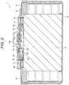
- FIG. 2 is a cross-sectional view taken along line A-A in FIG. 1
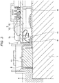
- FIG. 3 is a partially enlarged view of FIG. 2
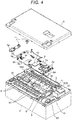
- FIG. 4 is an external perspective view before the circuit board of FIG. 1 is assembled
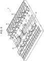
- FIG. 5 is an external perspective view of the back surface side of the circuit board
- FIG. 6 is a perspective view of the insulation cover.
- the assembled battery of the present embodiment has a structure in which elastic contact members 61 are provided on the back surface of the circuit board 6 so as to connect the circuit of the circuit board 6 and bus bars 5 between the single batteries 4 of the assembled battery, and the circuit board 6 is sandwiched between the elastic contact members 61 and claws 81 provided on a front surface 6a side of the circuit board 6.
- an assembled battery 1 includes the case 2 formed of a PBT resin, for example, having insulation properties and a lid 3 to be fitted to the case 2 and formed of a PBT resin, for example, having insulation properties similarly to the case 2, and components such as the plurality of single batteries 4 and the circuit board 6 are assembled in the case 2.
- the case 2 has a box shape with the top opened and the bottom closed.
- the single battery 4 has a rectangular shape, and a positive electrode terminal 41 and a negative electrode terminal 42 are provided on one surface thereof.
- a plurality of single batteries are arranged in a stacked manner in the longitudinal direction of the case 2 and housed therein.
- the plurality of single batteries 4 are disposed side by side inside the case 2 so that the positive electrode terminal 41 and the negative electrode terminal 42 of each single battery 4 are arranged on one surface side (an upper surface 43 side of the single battery 4), forming the battery assembly.
- the bus bars 5, which are conductive members made of copper, aluminum or the like, are arranged between adjacent terminals of the plurality of single batteries 4, and are welded and electrically connected to the terminals, respectively.
- the bus bar 5 is provided with a detection terminal 51.
- the detection terminal 51 is drawn out from the connection surface with the positive electrode terminal 41 or the negative electrode terminal 42 of the single battery 4 and is disposed along the upper surface of an insulation cover 8 at a position facing a back surface 6b of the board 6 between the positive electrode terminal 41 and the negative electrode terminal 42 of each single battery 4.
- the insulation cover 8 is disposed on the upper surface 43 side, which is the one surface side on which the positive electrode terminal 41 and the negative electrode terminal 42 of the single battery 4 are provided.
- the insulation cover 8 covers the upper surface 43 side of the single battery 4 held in the case 2 and maintains the insulation properties with respect to other components, and is formed of a PP resin, for example, having insulation properties.
- the insulation cover 8 covers the entire upper surface 43 of the plurality of single batteries 4 arranged in a stacked manner and has a size projecting laterally from the upper surface 43 of the single battery 4. In the insulation cover 8, openings are provided at positions corresponding to the positive electrode terminal 41 and the negative electrode terminal 42 of each single battery 4, so that the bus bar 5 is exposed.
- the insulation cover 8 is fixed to the case 2 by fastening plate-shaped metal bands 9 made of stainless steel or steel subjected to corrosion-resistant plating, to the case 2 with screws 71, and maintains the state where the single batteries 4 are housed inside the case 2.
- the plurality of claws 81 are provided at substantially regular intervals as support members for supporting the circuit board 6.
- the claws 81 are disposed to be opposed to the front surface 6a of the circuit board 6 and are in contact with the front surface 6a of the circuit board 6 by the reaction force of the elastic contact members 61.
- the claws 81 are provided integrally with the insulation cover 8.
- the circuit board 6 is arranged above the insulation cover 8. The outer corners of the circuit board 6 are fixed to the case 2 with screws 70.
- the circuit board 6 is composed of a laminated structure of multilayer copper foil patterns and, for example, insulating resin such as glass epoxy.
- the circuit board 6 has a plurality of wirings for detecting each of the terminal voltages of the plurality of single batteries 4.
- the element 62 and the control element 63 are connected to each other by copper foil patterns provided on the front surface 6a or the inner layer of the circuit board 6 to constitute a predetermined electric circuit.
- a connector 64 for communication with a high-order control circuit (not shown) of the assembled battery 1 is mounted on the circuit board 6 and is connected to an electric circuit of the circuit board 6.
- a shunt bus bar 65 which is a plate-shaped conductive member is attached in advance to the circuit board 6, and one end of the shunt bus bar 65 is fixed with the case 2 with a bolt 11 together with a terminal bus bar 53A of a conductive member made of copper, aluminum or the like.
- the terminal bus bar 53A is welded to the electrode terminal of the single battery 4 at one end in the stacking direction among the single batteries 4 arranged in a stacked manner inside the case 2.
- the other end of the shunt bus bar 65 is fixed to the case 2 at a position exposed from a hole formed at a corner on the long side of the lid 3, with the bolt 11 together with a terminal bus bar 52 to be fixed to the case 2.
- a terminal bus bar 53B connected to the contactor 10 is welded to the electrode terminal of the single battery 4 at the other end in the stacking direction among the single batteries 4 arranged in a stacked manner inside the case 2.
- the terminal bus bar 53B is fixed to the case 2 with the bolt 11.
- a bus bar (not shown) is connected to the other connecting portion of the contactor 10 and is connected to a terminal bus bar 54.
- the terminal bus bar 54 is fixed to the case 2 at a position exposed from the other hole formed at a corner on the long side of the lid 3. Even in the state where the lid 3 of the assembled battery 1 is attached to the case 2, parts of the terminal bus bars 52 and 54 are exposed from holes formed at corners on the long side of the lid 3, and serves as electrical connecting portions with an external device connected with the assembled battery 1.
- the elastic contact members 61 which are to be brought into pressure contact with the bus bars 5 by fixing the circuit board 6 to the case 2 are attached to the back surface 6b of the circuit board 6 facing the insulation cover 8.
- the elastic contact member 61 is formed by bending an elastic material such as phosphor bronze for springs.
- the elastic contact members 61 are provided correspondingly to a plurality of wirings of the circuit board 6 and are electrically connected to the corresponding wirings.
- the elastic contact members 61 are connected to the circuit of the circuit board 6 for monitoring the state of the single batteries 4 by being brought into contact with the detection terminals 51 of the bus bars 5.
- the elastic contact members 61 are mounted on the back surface 6b of the circuit board 6 and are disposed at positions corresponding to the detection terminals 51 of the respective bus bars 5 along the edge of the long side of the circuit board 6.
- the elastic contact members 61 are connected to the element 62 for monitoring the state of the single batteries 4, the control element 63 for driving the contactor 10 for electrically connecting and disconnecting the external apparatus (not shown) and the assembled battery 1, and for processing the state monitoring information of the single batteries 4, and the connector 64 for communication with the high-order control circuit, which are disposed on the front surface 6a opposite to the mounting surface for the elastic contact members 61 on the circuit board 6, by using copper foil patterns 66 on the surface or inner layer of the circuit board 6.
- the circuit board 6 is assembled from the upper surface side of the insulation cover 8 and fixed to the case 2.
- the fixation to the case 2 is carried out by entwisting the screws 70 into threaded holes 20 of the case 2.
- the elastic contact members 61 are mounted on the back surface 6b of the circuit board 6 at positions corresponding to the detection terminals 51 of the respective bus bars 5, and are brought into pressure contact with the detection terminals 51 by fixing the circuit board 6 to the case 2 with the screws 70.
- the circuit board 6 is urged in the separating direction away from the upper surface of the insulation cover 8 by the elastic force of the elastic contact members 61. Then, the claws 81 of the insulation cover 8 come in contact with the front surface 6a of the circuit board 6, and thereby the movement in the separating direction is regulated, and the distance between the circuit board 6 and the detection terminals 51 is determined. That is, the circuit board 6 is sandwiched between the elastic contact members 61 and the claws 81, whereby the distance between the bus bars 5 and the circuit board 6 is fixed. Therefore, the elastic contact members 61 are connected to the detection terminals 51 while holding an optional load, and can maintain the contact pressure of the contacting portions with the bus bars 5 without using screws or relay terminals.
- the circuit board 6 is fixed to the case 2, and the elastic contact members 61 are connected to the detection terminals 51 of the bus bars 5, and further the claws 81 are in contact with the front surface 6a of the circuit board 6, the circuit board 6 is not completely fixed with respect to the insulation cover 8 and is supported so as to be able to relatively move and deform in a direction along the board surface of the circuit board 6 and in the direction perpendicular to the board surface in a state of so-called floating support.
- the insulation cover 8 is deformed by assembling, or vibration is applied to the insulation cover 8, stress due to the deformation or the vibration can be prevented from acting on the circuit board 6. Therefore, occurrence of breakage of electronic components or disconnection due to peeling of solder on the circuit board 6 can be prevented in advance, and a highly reliable assembled battery can be obtained.
- FIG. 7 is an external perspective view of the assembled battery of the second embodiment
- FIG. 8 is a partially enlarged view showing a main part of the assembled battery of the second embodiment by using a cross section. It should to be noted that the same reference numerals are given to similar constituent elements to those in the first embodiment described above to omit detailed description thereof.
- a feature of the present embodiment is that screws 82 are fixed to the insulation cover 8 instead of the claws 81 of the first embodiment and the heads of the fixed screws 82 are brought into contact with the front surface 6a of the circuit board 6.
- bosses 83 each having a boss hole 83a are formed at the positions of the claws 81 of the first embodiment.
- the screws 82 are entwisted into the boss holes 83a of the bosses 83, and the head of the screw 82 is brought into contact with the front surface 6a of the circuit board 6.
- a stepped screw may be used for the screw 82, but a tapping screw may also be used.
- the circuit board 6 Since the heads of the screws 82 are brought into contact with the front surface 6a of the circuit board 6, movement of the circuit board 6 in the separating direction away from the upper surface of the insulation cover 8 is restricted and the circuit board 6 is supported at this position.
- the circuit board 6 is in the state of floating support in which the circuit board 6 is relatively movable and deformable in a direction along the board surface of the circuit board 6 and in the direction perpendicular to the board surface. Therefore, even if the insulation cover 8 is deformed by assembling or vibration is applied to the insulation cover 8, stress due to the deformation or the vibration can be prevented from acting on the circuit board 6. Accordingly, occurrence of breakage of electronic components and disconnection due to peeling of solder on the circuit board 6 can be prevented in advance, and a highly reliable assembled battery can be obtained.
- the circuit board 6 when the circuit board 6 is set above the upper surface of the insulation cover 8 in the assembling work, it is not necessary to elastically deform the claws 81 as in the first embodiment, and the setting is completed only by placing the circuit board 6 in a predetermined position so that the setting work of the circuit board 6 can be simplified.
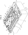
- FIG. 9 is an external perspective view of the assembled battery of the third embodiment
- FIG. 10 is an external perspective view of the bus bar of the third embodiment. It should be noted that the same reference numerals are given to similar constituent elements to those in the above embodiments, and a detailed description thereof will be omitted.
- each bus bar 5 is provided with a protrusion 501 as a support member for supporting the circuit board 6.
- the protrusion 501 is provided on part of the bus bar 5, and the detection terminal 51 is provided separately from the protrusion 501.
- the circuit board 6 is disposed between the protrusion 501 and the detection terminal 51 of the bus bar 5, and the front surface 6a of the circuit board 6 comes in contact with the tip of the protrusion 501.
- the tip of the protrusion 501 is subjected to an insulation treatment such as resin coating, and measures for insulation from the circuit board 6 has been carried out.
- the structure can be simplified and the assembly work can be made easier.
Landscapes
- Chemical & Material Sciences (AREA)
- Chemical Kinetics & Catalysis (AREA)
- Electrochemistry (AREA)
- General Chemical & Material Sciences (AREA)
- Engineering & Computer Science (AREA)
- Manufacturing & Machinery (AREA)
- Microelectronics & Electronic Packaging (AREA)
- Battery Mounting, Suspending (AREA)
- Connection Of Batteries Or Terminals (AREA)
- Secondary Cells (AREA)
Applications Claiming Priority (2)
| Application Number | Priority Date | Filing Date | Title |
|---|---|---|---|
| JP2015120982 | 2015-06-16 | ||
| PCT/JP2016/064670 WO2016203891A1 (fr) | 2015-06-16 | 2016-05-18 | Batterie assemblée |
Publications (3)
| Publication Number | Publication Date |
|---|---|
| EP3312902A1 true EP3312902A1 (fr) | 2018-04-25 |
| EP3312902A4 EP3312902A4 (fr) | 2019-02-06 |
| EP3312902B1 EP3312902B1 (fr) | 2020-01-01 |
Family
ID=57545111
Family Applications (1)
| Application Number | Title | Priority Date | Filing Date |
|---|---|---|---|
| EP16811366.0A Active EP3312902B1 (fr) | 2015-06-16 | 2016-05-18 | Batterie assemblée |
Country Status (5)
| Country | Link |
|---|---|
| US (1) | US10367183B2 (fr) |
| EP (1) | EP3312902B1 (fr) |
| JP (1) | JP6404473B2 (fr) |
| CN (1) | CN107710448B (fr) |
| WO (1) | WO2016203891A1 (fr) |
Families Citing this family (15)
| Publication number | Priority date | Publication date | Assignee | Title |
|---|---|---|---|---|
| US10734617B2 (en) | 2015-07-22 | 2020-08-04 | Murata Manufacturing Co., Ltd. | Battery module, power tool, and electronic apparatus |
| DE112017006651T5 (de) * | 2016-12-28 | 2019-10-17 | Gs Yuasa International Ltd. | Energiespeichervorrichtung |
| CN109994798B (zh) * | 2017-12-26 | 2025-08-15 | Sk新能源株式会社 | 电池模块及其制造方法 |
| KR102321513B1 (ko) * | 2018-08-21 | 2021-11-02 | 주식회사 엘지에너지솔루션 | 버스바 플레이트를 포함하는 배터리 모듈 |
| JP7159984B2 (ja) * | 2019-06-21 | 2022-10-25 | 株式会社デンソー | 電池モジュール |
| CN112151894B (zh) * | 2019-06-28 | 2022-04-26 | 宁德时代新能源科技股份有限公司 | 电池模组 |
| KR102813933B1 (ko) * | 2019-12-20 | 2025-05-27 | 주식회사 엘지에너지솔루션 | 전지 모듈 및 이를 포함하는 전지 팩 |
| JP7529415B2 (ja) * | 2020-02-27 | 2024-08-06 | 矢崎総業株式会社 | バスバーモジュール及びバスバーモジュールの組立方法 |
| JP7574652B2 (ja) * | 2021-01-15 | 2024-10-29 | 株式会社オートネットワーク技術研究所 | 外部接続バスバーおよび配線モジュール |
| CN112713344A (zh) * | 2021-01-18 | 2021-04-27 | 中国第一汽车股份有限公司 | 一种电池总成及电动车 |
| DE102021206790A1 (de) * | 2021-06-30 | 2023-01-05 | Robert Bosch Gesellschaft mit beschränkter Haftung | Akkupack |
| JPWO2023176417A1 (fr) * | 2022-03-18 | 2023-09-21 | ||
| US20230327293A1 (en) * | 2022-03-23 | 2023-10-12 | Ford Global Technologies, Llc | Bus bar welding solutions for traction battery packs |
| JP2025074399A (ja) * | 2023-10-30 | 2025-05-14 | 矢崎総業株式会社 | 組立体 |
| CN221978018U (zh) * | 2024-03-07 | 2024-11-08 | 惠州亿纬锂能股份有限公司 | 一种电池管理系统及电池包 |
Family Cites Families (11)
| Publication number | Priority date | Publication date | Assignee | Title |
|---|---|---|---|---|
| JP5018119B2 (ja) | 2007-02-16 | 2012-09-05 | パナソニック株式会社 | 蓄電ユニット |
| JP2009059663A (ja) | 2007-09-03 | 2009-03-19 | Honda Motor Co Ltd | 蓄電池ユニット |
| JP5285959B2 (ja) | 2008-05-27 | 2013-09-11 | 株式会社ケーヒン | 組電池の電源制御装置 |
| JP5340676B2 (ja) * | 2008-08-29 | 2013-11-13 | 三洋電機株式会社 | バッテリシステム |
| JP5372449B2 (ja) | 2008-09-24 | 2013-12-18 | 三洋電機株式会社 | バッテリシステム |
| KR101202542B1 (ko) * | 2009-07-17 | 2012-11-20 | 파나소닉 주식회사 | 전지 모듈과 이를 이용한 전지 팩 |
| US20150153390A1 (en) * | 2012-05-18 | 2015-06-04 | Hella Kgaa Hueck & Co. | Measuring electronics comprising a contact structure |
| JP5983108B2 (ja) * | 2012-07-05 | 2016-08-31 | 株式会社デンソー | 電池ユニット |
| DE102012219782A1 (de) * | 2012-10-29 | 2014-04-30 | Lisa Dräxlmaier GmbH | Batteriemodul |
| JP6164489B2 (ja) * | 2014-01-21 | 2017-07-19 | 株式会社オートネットワーク技術研究所 | 配線モジュール |
| JP6359362B2 (ja) | 2014-07-07 | 2018-07-18 | 株式会社東芝 | 電池モジュール |
-
2016
- 2016-05-18 CN CN201680026301.9A patent/CN107710448B/zh active Active
- 2016-05-18 EP EP16811366.0A patent/EP3312902B1/fr active Active
- 2016-05-18 JP JP2017524739A patent/JP6404473B2/ja active Active
- 2016-05-18 US US15/574,269 patent/US10367183B2/en active Active
- 2016-05-18 WO PCT/JP2016/064670 patent/WO2016203891A1/fr not_active Ceased
Also Published As
| Publication number | Publication date |
|---|---|
| CN107710448A (zh) | 2018-02-16 |
| JP6404473B2 (ja) | 2018-10-10 |
| EP3312902B1 (fr) | 2020-01-01 |
| US20180138483A1 (en) | 2018-05-17 |
| JPWO2016203891A1 (ja) | 2018-03-08 |
| EP3312902A4 (fr) | 2019-02-06 |
| CN107710448B (zh) | 2020-06-09 |
| US10367183B2 (en) | 2019-07-30 |
| WO2016203891A1 (fr) | 2016-12-22 |
Similar Documents
| Publication | Publication Date | Title |
|---|---|---|
| EP3312902B1 (fr) | Batterie assemblée | |
| US8580423B2 (en) | Bus bar holder and battery pack including the same | |
| US9627151B2 (en) | Electrical storage module | |
| CN102468473B (zh) | 电池模块的连接构造、电池模块及电池模块端子组装方法 | |
| KR102247392B1 (ko) | 배터리 모듈 | |
| US9343725B2 (en) | Bus bar module and power supply unit | |
| EP3082177B1 (fr) | Module de cellule secondaire | |
| JP6202338B2 (ja) | 配線モジュール、配線モジュール中間体、及び配線モジュールの製造方法 | |
| US9972870B2 (en) | Battery module | |
| US20160072113A1 (en) | Bus bar module and power supply device | |
| JP2013080693A (ja) | 電池用配線モジュール | |
| JP6044505B2 (ja) | 組電池ユニット | |
| US20140370355A1 (en) | Battery pack | |
| US10770700B2 (en) | Battery pack | |
| US20190386282A1 (en) | Connection module | |
| JP2018045825A (ja) | 電池モジュール及び電池パック | |
| US9936594B2 (en) | Wiring module | |
| US20150017563A1 (en) | Fuel cell unit and fuel cell vehicle | |
| CN104300106A (zh) | 具有模块盖的电池模块 | |
| CN109565023B (zh) | 布线模块 | |
| JP6452402B2 (ja) | 蓄電装置 | |
| JP2019106253A (ja) | 電池モジュール | |
| JP7076259B2 (ja) | 燃料電池システム | |
| US9362543B2 (en) | Battery pack | |
| JP2018037186A (ja) | 電池パック |
Legal Events
| Date | Code | Title | Description |
|---|---|---|---|
| STAA | Information on the status of an ep patent application or granted ep patent |
Free format text: STATUS: THE INTERNATIONAL PUBLICATION HAS BEEN MADE |
|
| PUAI | Public reference made under article 153(3) epc to a published international application that has entered the european phase |
Free format text: ORIGINAL CODE: 0009012 |
|
| STAA | Information on the status of an ep patent application or granted ep patent |
Free format text: STATUS: REQUEST FOR EXAMINATION WAS MADE |
|
| 17P | Request for examination filed |
Effective date: 20180116 |
|
| AK | Designated contracting states |
Kind code of ref document: A1 Designated state(s): AL AT BE BG CH CY CZ DE DK EE ES FI FR GB GR HR HU IE IS IT LI LT LU LV MC MK MT NL NO PL PT RO RS SE SI SK SM TR |
|
| AX | Request for extension of the european patent |
Extension state: BA ME |
|
| DAV | Request for validation of the european patent (deleted) | ||
| DAX | Request for extension of the european patent (deleted) | ||
| RIC1 | Information provided on ipc code assigned before grant |
Ipc: H01M 10/44 20060101ALI20181221BHEP Ipc: H01M 2/10 20060101AFI20181221BHEP Ipc: H01M 2/20 20060101ALI20181221BHEP Ipc: H01M 10/48 20060101ALI20181221BHEP |
|
| A4 | Supplementary search report drawn up and despatched |
Effective date: 20190109 |
|
| GRAP | Despatch of communication of intention to grant a patent |
Free format text: ORIGINAL CODE: EPIDOSNIGR1 |
|
| STAA | Information on the status of an ep patent application or granted ep patent |
Free format text: STATUS: GRANT OF PATENT IS INTENDED |
|
| INTG | Intention to grant announced |
Effective date: 20190712 |
|
| GRAS | Grant fee paid |
Free format text: ORIGINAL CODE: EPIDOSNIGR3 |
|
| GRAA | (expected) grant |
Free format text: ORIGINAL CODE: 0009210 |
|
| STAA | Information on the status of an ep patent application or granted ep patent |
Free format text: STATUS: THE PATENT HAS BEEN GRANTED |
|
| RIN1 | Information on inventor provided before grant (corrected) |
Inventor name: SEKINE ATSUSHI |
|
| AK | Designated contracting states |
Kind code of ref document: B1 Designated state(s): AL AT BE BG CH CY CZ DE DK EE ES FI FR GB GR HR HU IE IS IT LI LT LU LV MC MK MT NL NO PL PT RO RS SE SI SK SM TR |
|
| REG | Reference to a national code |
Ref country code: GB Ref legal event code: FG4D |
|
| REG | Reference to a national code |
Ref country code: CH Ref legal event code: EP Ref country code: AT Ref legal event code: REF Ref document number: 1220914 Country of ref document: AT Kind code of ref document: T Effective date: 20200115 |
|
| REG | Reference to a national code |
Ref country code: IE Ref legal event code: FG4D |
|
| REG | Reference to a national code |
Ref country code: DE Ref legal event code: R096 Ref document number: 602016027507 Country of ref document: DE |
|
| REG | Reference to a national code |
Ref country code: DE Ref legal event code: R082 Ref document number: 602016027507 Country of ref document: DE Representative=s name: MERH-IP MATIAS ERNY REICHL HOFFMANN PATENTANWA, DE Ref country code: DE Ref legal event code: R081 Ref document number: 602016027507 Country of ref document: DE Owner name: VEHICLE ENERGY JAPAN INC., HITACHINAKA-SHI, JP Free format text: FORMER OWNER: HITACHI AUTOMOTIVE SYSTEMS, LTD., HITACHINAKA-SHI, IBARAKI, JP |
|
| REG | Reference to a national code |
Ref country code: NL Ref legal event code: MP Effective date: 20200101 |
|
| REG | Reference to a national code |
Ref country code: LT Ref legal event code: MG4D |
|
| PG25 | Lapsed in a contracting state [announced via postgrant information from national office to epo] |
Ref country code: RS Free format text: LAPSE BECAUSE OF FAILURE TO SUBMIT A TRANSLATION OF THE DESCRIPTION OR TO PAY THE FEE WITHIN THE PRESCRIBED TIME-LIMIT Effective date: 20200101 Ref country code: FI Free format text: LAPSE BECAUSE OF FAILURE TO SUBMIT A TRANSLATION OF THE DESCRIPTION OR TO PAY THE FEE WITHIN THE PRESCRIBED TIME-LIMIT Effective date: 20200101 Ref country code: NO Free format text: LAPSE BECAUSE OF FAILURE TO SUBMIT A TRANSLATION OF THE DESCRIPTION OR TO PAY THE FEE WITHIN THE PRESCRIBED TIME-LIMIT Effective date: 20200401 Ref country code: NL Free format text: LAPSE BECAUSE OF FAILURE TO SUBMIT A TRANSLATION OF THE DESCRIPTION OR TO PAY THE FEE WITHIN THE PRESCRIBED TIME-LIMIT Effective date: 20200101 Ref country code: PT Free format text: LAPSE BECAUSE OF FAILURE TO SUBMIT A TRANSLATION OF THE DESCRIPTION OR TO PAY THE FEE WITHIN THE PRESCRIBED TIME-LIMIT Effective date: 20200527 Ref country code: CZ Free format text: LAPSE BECAUSE OF FAILURE TO SUBMIT A TRANSLATION OF THE DESCRIPTION OR TO PAY THE FEE WITHIN THE PRESCRIBED TIME-LIMIT Effective date: 20200101 Ref country code: LT Free format text: LAPSE BECAUSE OF FAILURE TO SUBMIT A TRANSLATION OF THE DESCRIPTION OR TO PAY THE FEE WITHIN THE PRESCRIBED TIME-LIMIT Effective date: 20200101 |
|
| PG25 | Lapsed in a contracting state [announced via postgrant information from national office to epo] |
Ref country code: IS Free format text: LAPSE BECAUSE OF FAILURE TO SUBMIT A TRANSLATION OF THE DESCRIPTION OR TO PAY THE FEE WITHIN THE PRESCRIBED TIME-LIMIT Effective date: 20200501 Ref country code: GR Free format text: LAPSE BECAUSE OF FAILURE TO SUBMIT A TRANSLATION OF THE DESCRIPTION OR TO PAY THE FEE WITHIN THE PRESCRIBED TIME-LIMIT Effective date: 20200402 Ref country code: BG Free format text: LAPSE BECAUSE OF FAILURE TO SUBMIT A TRANSLATION OF THE DESCRIPTION OR TO PAY THE FEE WITHIN THE PRESCRIBED TIME-LIMIT Effective date: 20200401 Ref country code: SE Free format text: LAPSE BECAUSE OF FAILURE TO SUBMIT A TRANSLATION OF THE DESCRIPTION OR TO PAY THE FEE WITHIN THE PRESCRIBED TIME-LIMIT Effective date: 20200101 Ref country code: LV Free format text: LAPSE BECAUSE OF FAILURE TO SUBMIT A TRANSLATION OF THE DESCRIPTION OR TO PAY THE FEE WITHIN THE PRESCRIBED TIME-LIMIT Effective date: 20200101 Ref country code: HR Free format text: LAPSE BECAUSE OF FAILURE TO SUBMIT A TRANSLATION OF THE DESCRIPTION OR TO PAY THE FEE WITHIN THE PRESCRIBED TIME-LIMIT Effective date: 20200101 |
|
| REG | Reference to a national code |
Ref country code: DE Ref legal event code: R097 Ref document number: 602016027507 Country of ref document: DE |
|
| PG25 | Lapsed in a contracting state [announced via postgrant information from national office to epo] |
Ref country code: ES Free format text: LAPSE BECAUSE OF FAILURE TO SUBMIT A TRANSLATION OF THE DESCRIPTION OR TO PAY THE FEE WITHIN THE PRESCRIBED TIME-LIMIT Effective date: 20200101 Ref country code: DK Free format text: LAPSE BECAUSE OF FAILURE TO SUBMIT A TRANSLATION OF THE DESCRIPTION OR TO PAY THE FEE WITHIN THE PRESCRIBED TIME-LIMIT Effective date: 20200101 Ref country code: SK Free format text: LAPSE BECAUSE OF FAILURE TO SUBMIT A TRANSLATION OF THE DESCRIPTION OR TO PAY THE FEE WITHIN THE PRESCRIBED TIME-LIMIT Effective date: 20200101 Ref country code: RO Free format text: LAPSE BECAUSE OF FAILURE TO SUBMIT A TRANSLATION OF THE DESCRIPTION OR TO PAY THE FEE WITHIN THE PRESCRIBED TIME-LIMIT Effective date: 20200101 Ref country code: EE Free format text: LAPSE BECAUSE OF FAILURE TO SUBMIT A TRANSLATION OF THE DESCRIPTION OR TO PAY THE FEE WITHIN THE PRESCRIBED TIME-LIMIT Effective date: 20200101 Ref country code: SM Free format text: LAPSE BECAUSE OF FAILURE TO SUBMIT A TRANSLATION OF THE DESCRIPTION OR TO PAY THE FEE WITHIN THE PRESCRIBED TIME-LIMIT Effective date: 20200101 |
|
| PLBE | No opposition filed within time limit |
Free format text: ORIGINAL CODE: 0009261 |
|
| STAA | Information on the status of an ep patent application or granted ep patent |
Free format text: STATUS: NO OPPOSITION FILED WITHIN TIME LIMIT |
|
| REG | Reference to a national code |
Ref country code: AT Ref legal event code: MK05 Ref document number: 1220914 Country of ref document: AT Kind code of ref document: T Effective date: 20200101 |
|
| REG | Reference to a national code |
Ref country code: DE Ref legal event code: R079 Ref document number: 602016027507 Country of ref document: DE Free format text: PREVIOUS MAIN CLASS: H01M0002100000 Ipc: H01M0050200000 |
|
| 26N | No opposition filed |
Effective date: 20201002 |
|
| PG25 | Lapsed in a contracting state [announced via postgrant information from national office to epo] |
Ref country code: IT Free format text: LAPSE BECAUSE OF FAILURE TO SUBMIT A TRANSLATION OF THE DESCRIPTION OR TO PAY THE FEE WITHIN THE PRESCRIBED TIME-LIMIT Effective date: 20200101 Ref country code: CH Free format text: LAPSE BECAUSE OF NON-PAYMENT OF DUE FEES Effective date: 20200531 Ref country code: MC Free format text: LAPSE BECAUSE OF FAILURE TO SUBMIT A TRANSLATION OF THE DESCRIPTION OR TO PAY THE FEE WITHIN THE PRESCRIBED TIME-LIMIT Effective date: 20200101 Ref country code: AT Free format text: LAPSE BECAUSE OF FAILURE TO SUBMIT A TRANSLATION OF THE DESCRIPTION OR TO PAY THE FEE WITHIN THE PRESCRIBED TIME-LIMIT Effective date: 20200101 Ref country code: LI Free format text: LAPSE BECAUSE OF NON-PAYMENT OF DUE FEES Effective date: 20200531 |
|
| PG25 | Lapsed in a contracting state [announced via postgrant information from national office to epo] |
Ref country code: PL Free format text: LAPSE BECAUSE OF FAILURE TO SUBMIT A TRANSLATION OF THE DESCRIPTION OR TO PAY THE FEE WITHIN THE PRESCRIBED TIME-LIMIT Effective date: 20200101 Ref country code: SI Free format text: LAPSE BECAUSE OF FAILURE TO SUBMIT A TRANSLATION OF THE DESCRIPTION OR TO PAY THE FEE WITHIN THE PRESCRIBED TIME-LIMIT Effective date: 20200101 |
|
| REG | Reference to a national code |
Ref country code: BE Ref legal event code: MM Effective date: 20200531 |
|
| GBPC | Gb: european patent ceased through non-payment of renewal fee |
Effective date: 20200518 |
|
| PG25 | Lapsed in a contracting state [announced via postgrant information from national office to epo] |
Ref country code: LU Free format text: LAPSE BECAUSE OF NON-PAYMENT OF DUE FEES Effective date: 20200518 |
|
| PG25 | Lapsed in a contracting state [announced via postgrant information from national office to epo] |
Ref country code: IE Free format text: LAPSE BECAUSE OF NON-PAYMENT OF DUE FEES Effective date: 20200518 Ref country code: GB Free format text: LAPSE BECAUSE OF NON-PAYMENT OF DUE FEES Effective date: 20200518 |
|
| PG25 | Lapsed in a contracting state [announced via postgrant information from national office to epo] |
Ref country code: BE Free format text: LAPSE BECAUSE OF NON-PAYMENT OF DUE FEES Effective date: 20200531 |
|
| PG25 | Lapsed in a contracting state [announced via postgrant information from national office to epo] |
Ref country code: TR Free format text: LAPSE BECAUSE OF FAILURE TO SUBMIT A TRANSLATION OF THE DESCRIPTION OR TO PAY THE FEE WITHIN THE PRESCRIBED TIME-LIMIT Effective date: 20200101 Ref country code: MT Free format text: LAPSE BECAUSE OF FAILURE TO SUBMIT A TRANSLATION OF THE DESCRIPTION OR TO PAY THE FEE WITHIN THE PRESCRIBED TIME-LIMIT Effective date: 20200101 Ref country code: CY Free format text: LAPSE BECAUSE OF FAILURE TO SUBMIT A TRANSLATION OF THE DESCRIPTION OR TO PAY THE FEE WITHIN THE PRESCRIBED TIME-LIMIT Effective date: 20200101 |
|
| PG25 | Lapsed in a contracting state [announced via postgrant information from national office to epo] |
Ref country code: MK Free format text: LAPSE BECAUSE OF FAILURE TO SUBMIT A TRANSLATION OF THE DESCRIPTION OR TO PAY THE FEE WITHIN THE PRESCRIBED TIME-LIMIT Effective date: 20200101 Ref country code: AL Free format text: LAPSE BECAUSE OF FAILURE TO SUBMIT A TRANSLATION OF THE DESCRIPTION OR TO PAY THE FEE WITHIN THE PRESCRIBED TIME-LIMIT Effective date: 20200101 |
|
| PGFP | Annual fee paid to national office [announced via postgrant information from national office to epo] |
Ref country code: DE Payment date: 20250402 Year of fee payment: 10 |
|
| PGFP | Annual fee paid to national office [announced via postgrant information from national office to epo] |
Ref country code: FR Payment date: 20250401 Year of fee payment: 10 |