EP3943809B1 - Kraftfahrzeugscheinwerfer mit projektionslichtmodulen - Google Patents
Kraftfahrzeugscheinwerfer mit projektionslichtmodulen Download PDFInfo
- Publication number
- EP3943809B1 EP3943809B1 EP21186577.9A EP21186577A EP3943809B1 EP 3943809 B1 EP3943809 B1 EP 3943809B1 EP 21186577 A EP21186577 A EP 21186577A EP 3943809 B1 EP3943809 B1 EP 3943809B1
- Authority
- EP
- European Patent Office
- Prior art keywords
- light
- guide plate
- light guide
- motor vehicle
- additional
- Prior art date
- Legal status (The legal status is an assumption and is not a legal conclusion. Google has not performed a legal analysis and makes no representation as to the accuracy of the status listed.)
- Active
Links
Images


Classifications
-
- F—MECHANICAL ENGINEERING; LIGHTING; HEATING; WEAPONS; BLASTING
- F21—LIGHTING
- F21S—NON-PORTABLE LIGHTING DEVICES; SYSTEMS THEREOF; VEHICLE LIGHTING DEVICES SPECIALLY ADAPTED FOR VEHICLE EXTERIORS
- F21S41/00—Illuminating devices specially adapted for vehicle exteriors, e.g. headlamps
- F21S41/20—Illuminating devices specially adapted for vehicle exteriors, e.g. headlamps characterised by refractors, transparent cover plates, light guides or filters
- F21S41/24—Light guides
-
- F—MECHANICAL ENGINEERING; LIGHTING; HEATING; WEAPONS; BLASTING
- F21—LIGHTING
- F21S—NON-PORTABLE LIGHTING DEVICES; SYSTEMS THEREOF; VEHICLE LIGHTING DEVICES SPECIALLY ADAPTED FOR VEHICLE EXTERIORS
- F21S41/00—Illuminating devices specially adapted for vehicle exteriors, e.g. headlamps
- F21S41/10—Illuminating devices specially adapted for vehicle exteriors, e.g. headlamps characterised by the light source
- F21S41/14—Illuminating devices specially adapted for vehicle exteriors, e.g. headlamps characterised by the light source characterised by the type of light source
- F21S41/141—Light emitting diodes [LED]
- F21S41/143—Light emitting diodes [LED] the main emission direction of the LED being parallel to the optical axis of the illuminating device
-
- F—MECHANICAL ENGINEERING; LIGHTING; HEATING; WEAPONS; BLASTING
- F21—LIGHTING
- F21S—NON-PORTABLE LIGHTING DEVICES; SYSTEMS THEREOF; VEHICLE LIGHTING DEVICES SPECIALLY ADAPTED FOR VEHICLE EXTERIORS
- F21S41/00—Illuminating devices specially adapted for vehicle exteriors, e.g. headlamps
- F21S41/10—Illuminating devices specially adapted for vehicle exteriors, e.g. headlamps characterised by the light source
- F21S41/14—Illuminating devices specially adapted for vehicle exteriors, e.g. headlamps characterised by the light source characterised by the type of light source
- F21S41/141—Light emitting diodes [LED]
- F21S41/147—Light emitting diodes [LED] the main emission direction of the LED being angled to the optical axis of the illuminating device
-
- F—MECHANICAL ENGINEERING; LIGHTING; HEATING; WEAPONS; BLASTING
- F21—LIGHTING
- F21S—NON-PORTABLE LIGHTING DEVICES; SYSTEMS THEREOF; VEHICLE LIGHTING DEVICES SPECIALLY ADAPTED FOR VEHICLE EXTERIORS
- F21S41/00—Illuminating devices specially adapted for vehicle exteriors, e.g. headlamps
- F21S41/20—Illuminating devices specially adapted for vehicle exteriors, e.g. headlamps characterised by refractors, transparent cover plates, light guides or filters
- F21S41/25—Projection lenses
- F21S41/255—Lenses with a front view of circular or truncated circular outline
Definitions
- the present invention relates to a motor vehicle headlight according to the preamble of claim 1.
- Such a motor vehicle headlight is from the FR 3 079 597 A1 already known.
- a projection light module comprises a first projection light module which comprises a first semiconductor light source, a first projection lens and a first additional light source as well as a first light guide plate.
- the first projection lens comprises a first optical axis and a first light entry surface that can be illuminated with the first additional light source through the first light guide plate.
- the first additional light source is arranged on a narrow side of the first light guide plate such that light emanating from the first additional light source enters the first light guide plate transversely to the first optical axis.
- the first light guide plate has a front emission side facing the first projection lens and a rear deflection side opposite the front emission side, as well as a first part closer to the first optical axis and a second part further away from the optical axis.
- the first part and the second part are components of the first light guide plate.
- a matrix function is understood here to mean that the high beam distribution has a plurality of matrix elements in the form of segments of the light distribution that can be individually darkened in order to avoid dazzling other road users and at the same time to achieve good illumination of the road with bright segments.
- both projection lenses of the projection light modules appear luminous even when only the low beam is switched on in order to achieve a uniform appearance between the partial high beam and the low beam
- an additional LED was previously installed on the LED board of the matrix high beam module and its light was directed to the lens entrance side via two metallized reflectors.
- the arrangement of the reflectors was chosen so that the light path of the matrix function is not disturbed and the reflection surface of the second reflector is close to the image plane of the projection lens.
- the matrix elements of the high beam distribution are generated via collecting lenses assigned to the respective LEDs, i.e. with a refractive attachment lens, and their imaging via the downstream common projection lens, the additional light used to brighten the projection lens runs via two metallized reflectors.
- the optical system for lens illumination of the high beam module differs from that of the low beam module. This means that the light color of the additional light differs from that of the low beam.
- the inevitable inclined arrangement of the second reflector of the known additional light means that it is not possible to get close enough to the image plane of the projection lens. This leads to an inhomogeneous appearance of the luminous lens.
- a homogeneous luminance is generated at the height of the front optics of the matrix light module using a light guide plate.
- the light guide is fed with additional light from one LED on the side of the matrix light LED board.
- the light propagating within the light guide plate is directed towards the projection lens by prisms attached to the back of the plate. This results in homogeneous illumination of the light guide plate.
- This and the position of the light guide in the image plane of the projection lens mean that the viewer already has a homogeneous appearance of the projection lens that corresponds to the shape of the projection lens, even if the projection lens is not completely illuminated for its actual purpose of generating a spotlight light distribution.
- the tilted arrangement further improves the homogeneity of the illumination of the first projection lens with additional light.
- the object of the invention is to achieve an even more uniform appearance between the partial high beam and the dipped beam.
- a preferred embodiment is characterized in that the first projection light module is a high beam module.
- the matrix high beam has the property that the appearance of the lens changes depending on the position of the light and dark matrix elements. Therefore, the invention, which ensures a more uniform appearance, has a particularly advantageous effect here.
- the motor vehicle headlight comprises a second projection light module comprising a second semiconductor light source, a second projection lens and a second additional light source as well as a second Light guide plate
- the second projection lens has a second optical axis and a second light entry surface which can be illuminated with the second additional light source through the second light guide plate
- the second additional light source is arranged on a narrow side of the second light guide plate such that light emanating from the second additional light source enters the second light guide plate transversely to the second optical axis and the second light guide plate has a front emission side facing the second projection lens and a rear deflection side opposite the front emission side as well as a first part closer to the second optical axis and a second part further away from the second optical axis, and that the light guide plate is arranged in a tilted position in which the first part of the second light guide plate is further away from the second projection lens along the second optical axis than the second part of the second light guide plate.
- the second projection light module has a mirror cover running from the back to the front in the motor vehicle headlight and that the light guide plate is arranged below the mirror cover.
- This design creates a low beam module with improved illumination of the projection lens.
- This design also surprisingly shows that the tilted arrangement further improves the homogeneity of the illumination of the second projection lens with additional light.
- a further preferred embodiment is characterized in that the light color of the additional light source is unchangeable and differs from the light color of the high beam and/or the low beam.
- This embodiment results in a fixed illumination of the remaining colorless light guide that is deliberately different in color from the light color of the high beam and/or the low beam and thus a correspondingly multi-colored illumination of the projection lens.
- a further preferred embodiment is characterized in that the first light guide plate and/or the second light guide plate has at least one colored region.
- the colored area is a light entry area of the otherwise colorless transparent light guide plate.
- the colored region is a colored coated light entry region of the otherwise colorless light guide plate.
- this attachment optic would be two-colored, as a so-called 2-component (2K) part.
- 2K 2-component
- the interface of the two components together with the entrance surface can be optimized with regard to a uniform colored illumination of the rest of the light guide (2.2).
- Another variant instead of a two-color light guide plate consists in a coating of the entrance surface of the otherwise colorless light guide plate, the optical properties of which are designed in such a way that it is only transparent to light of a fixed color or wavelength and absorbs or reflects all light of other colors or wavelengths.
- the light colour of the first and/or second additional light source is controllably variable and may differ from the light colour of the high beam and/or the low beam.
- first and/or second additional light source has individually controllable, differently colored light-emitting diodes.
- a temporally changing color of the lens illumination in particular a color that is deliberately different from the main light functions of the low beam and the high beam, cannot be realized with the above-mentioned state of the art.
- This limitation of the possible appearances with which, for example, a colored welcome light can be created with the headlights is eliminated by this design.
- a further preferred embodiment is characterized in that the individually controllable, differently colored light-emitting diodes comprise a red light-emitting light-emitting diode, a green light-emitting light-emitting diode and a blue light-emitting light-emitting diode.
- An alternative to the use of the light guide plate according to the invention could be to use an attachment optic that is common to both functions, i.e., for the function of generating a light distribution and the function of uniform illumination of the projection lenses.
- the Figure 1 a motor vehicle headlight 10 with a main beam direction 12 pointing forward v.
- the designation h indicates a rear position
- the designations r and 1 indicate a right side and a left side
- the designations o and u indicate an upper and a lower position.
- the motor vehicle headlight 10 has a first projection light module 14 and a second Projection light module 16.
- the location and position information front, rear, right, left, top and bottom each refer to an orientation of the motor vehicle headlight in space when used as intended in a motor vehicle.
- Figure 2 shows a vertical section running between front v and rear h through the motor vehicle headlight 10, which has a housing 18 whose light exit opening is covered by a transparent cover plate 20.
- the first projection light module 14 has a first semiconductor light source 22, a first projection lens 24 and a first additional light source 26 as well as a first light guide plate 28.
- the first projection lens 24 has a first optical axis 30 and a first light entry surface 32. The first light entry surface 32 can be illuminated with additional light 34 from the first additional light source 26 through the first light guide plate 28.
- the first additional light source 26 is arranged on a narrow side 36 of the first light guide plate 28 such that additional light 34 emanating from the first additional light source 26 enters the first light guide plate 28 transversely (namely laterally, in particular in the right-left direction) to the first optical axis 30 running in the front-back direction, and the first light guide plate 28 has a first front radiation side 38 facing the first projection lens 24 and a first rear deflection side 40 opposite the first front radiation side 38, as well as a closer to the first optical axis 30 and a second part 44 further away from the first optical axis 30.
- the first light guide plate 28 is arranged in a tilted position in which the first part 42 of the first light guide plate 28 is further away from the first projection lens 24 along the first optical axis 30 than the second part 44 of the first light guide plate 28.
- the light guide plate is not arranged at right angles to the first optical axis, particularly in the vertical section in which the first optical axis 30 also lies.
- Figure 3 shows the first projection light module 14 from the front.
- two additional light sources 26 are provided, one of which is arranged on a right narrow side 36.r and one on a left narrow side 36.1.
- the additional light 34 emanating from the additional light sources 26 enters the first light guide plate 28 from the side and is distributed evenly in the first light guide plate 28, also through internal total reflection.
- the additional light 34 is deflected so steeply to the first front emission side 38 of the first light guide plate 28 that it emerges there evenly distributed.
- the emitted additional light 34 is at least in the vertical Direction so that it evenly illuminates the first light entry surface 32 of the first projection lens 24.
- the Figures 2 and 3 The first projection light module 14 shown is a high beam module.
- the light emanating from the first semiconductor light source 22 is not shaded or redirected by a horizontal aperture.
- the first semiconductor light source 22 of the first projection light module 14 has n LEDs arranged next to one another, each of which illuminates exactly one first optical attachment section 56 of a first optical attachment 50 that is assigned to it alone.
- the number of first optical attachment sections 56 is also equal to n.
- the number n here is equal to 6, without n being limited to this value.
- the individual LEDs and the first additional light source 26 can be individually controlled with a control device 58 of the first projection light module 14.
- the Figure 3 visible light exit surfaces of the first optical attachment sections 56 are projected forwards by the first projection lens 24, with the images being arranged in the same way as the light exit surfaces of the first optical attachment sections 56. By darkening individual LEDs, sections of the high beam distribution can be darkened individually in order to avoid blinding other road users.
- the control unit 58 processes signals from a vehicle environment sensor system, e.g. a camera and/or radar sensors.
- the first (upper) part 42 of the first light guide plate 28 is located just below the first optical attachment sections 56 and in or near the imaging plane of a first projection lens 24 or a projection lens system. This enables homogeneous illumination of the first projection lens 24, which as such is also visible at small (e.g. less than 5°) viewing angles to the first optical axis 30 of the first projection lens 24.
- FIG 4 shows the motor vehicle headlight 10 with a second projection light module 16.
- the second projection light module 16 has a second semiconductor light source 74, a second projection lens 60 and a second additional light source 62 as well as a second light guide plate 64.
- the second projection lens 60 has a second optical axis 66 and a second light entry surface 54, which can be illuminated with the second additional light source 62 through the second light guide plate 64.
- the second additional light source 62 is arranged on a narrow side of the second light guide plate 64 such that light emanating from the second additional light source 62 enters the second light guide plate 64 transversely to the second optical axis 66.
- the second light guide plate 64 has a second front Radiation side 68 and a second rear deflection side 70 opposite the second front radiation side 68 as well as a first part 43 located closer to the second optical axis 66 and a second part 45 located further away from the second optical axis 66.
- the second light guide plate 64 is arranged in a tilted position in which the first part 43 of the second light guide plate 64 is located further away from the second projection lens 60 along the second optical axis 66 than the second part 45 of the second light guide plate 64.
- the second light guide plate 64 is not arranged at a right angle to the second optical axis 66, particularly in the vertical section in which the second optical axis 66 also lies.
- the second projection light module 16 has a mirror cover 72 running from back to front in the motor vehicle headlight 10 and that the second light guide plate 64 is arranged below the mirror cover 72.
- the mirror aperture 72 has a reflective surface facing the second semiconductor light source 74 and the second optical attachment 76, which extends from the back to the front into the focal area of the second optical attachment 76 and the second projection lens 60.
- the second optical attachment 76 is here a half-shell reflector with an ellipsoidal basic shape.
- the second semiconductor light source is arranged in a focal point of the half-shell reflector.
- a second focal point or focal area of the half-shell reflector is intersected by the diaphragm edge 78.
- the diaphragm edge 78 of the mirror diaphragm 72 located in the focal area is imaged by the second projection lens 60 as a light-dark boundary of a low beam distribution running between right and left.
- Figure 5 shows a front view of the second projection light module 16 with the aperture edge 78 of the mirror aperture 72 running between the right and left, the second attachment optics 76 arranged above the mirror aperture 72 and the second light guide plate 64 arranged below the mirror aperture 72.
- the second optical attachment 76 can be designed as a lens or light guide.
- the light guide plates 28, 64 are preferably made of the same light guide material as the optical attachment.
- the light guide plates produce the same light color as the optical attachment. This applies at least if, for example, the first additional light source emits light of the same color as the first semiconductor light source.
- a preferred embodiment provides for the use of colored LEDs as additional light sources.
- These additional light sources advantageously each have three LED chips R, G, B arranged closely next to one another, which together form a second semiconductor light source 74. de.
- FIG. 6 shows a top view of such an arrangement.
- the main radiation direction of this arrangement is perpendicular to the plane of the drawing.
- Each of these chips R, G, B emits a different light color that is permanently assigned to it, ideally red, green and blue.
- the color of the light emitted by the additional light source and thus of the additional light can be adjusted almost freely according to the RGB color model.
- the colored LEDs R, G, B are controlled by the control unit 58.
- the control unit 58 As already generally described for the light of the additional light sources, the same applies to the colored light of RGB LEDs.
- R, G, B that this light is fed into the light guide plate and deflected by a prism structure on the deflection side of the light guide plate 28, 64 in the direction of an imaging projection lens 24, 60.
- This could, for example, convert the appearance of a motor vehicle headlight 10 into the appearance of a rear light.
- the low beam and the high beam could be switched off and the associated projection lenses 24, 60 could be temporarily illuminated red in order to fulfill a tail light function and/or a brake light function.
- Figure 7 shows that the light guide plate 28 and/or 64 can be designed entirely or partially from a colored transparent material as an alternative to the use of colored light sources and this light guide plate is then fed with a white LED. This applies in particular to the area 80 of the feed or parts thereof.
- Such a light guide plate 28, 64 would be two-coloured, which can be produced as a so-called 2-component (2K) part using a corresponding 2K injection molding process.
- the interface between the two components of the light guide plate 28, 64, which are then different in color, together with the light entry surface of the light guide plate 28, 64 can be optimized with regard to uniform colored illumination of the rest of the light guide plate.
- Another variant instead of a two-color light guide plate consists in a coating of the entrance surface of the otherwise colorless light guide plate, the optical properties of which are designed in such a way that it is only transparent to light of a fixed color or wavelength and absorbs or reflects all light of other colors or wavelengths.
- the light guide plate 28, 64 has a narrow side 36, via which light from an additional light source 26, 62 (compare Figures 2 to 4 ) is fed into the light guide plate 28, 64.
- the narrow side 36 closes off a coupling prism which has a trapezoidal cross-section and extends over the height of the prism.
- the narrow side 36 forms one of the two parallel surfaces of the prism.
- the surface of the prism parallel to it forms a transition surface with which the area 80 of the feed, which is identical to the prism here, merges into the rest of the light guide plate.
- the light from the additional light source fed into the light guide plate via the colored area 80 of the feed is reflected at the obliquely positioned boundary surfaces of the prismatic region 31 reduce the opening angle of the light fed in by internal total reflections.
- This light is then deflected at a preferably curved edge region into a region of the circuit board that has a flat, tilted central surface.
- This region is delimited to the rear by a deflection surface and to the front by a radiation surface.
- Deflection elements are arranged in the deflection surface, which have, for example, vertical edges that delimit oblique prism surfaces.
- the deflection elements are shaped in such a way that light from the additional light source incident on them from the interior of the light guide plate is deflected by internal total reflections so steeply to the front radiation surface that it exits the light guide plate there, with the light preferably being emitted obliquely upwards.
- Deflection elements in the shape of roller sections are preferably arranged in the radiation surface, which distribute the light exiting from the radiation surface so widely that it homogeneously illuminates the light entry surface of the projection lens following in the beam path.
- the roller sections preferably extend from the narrow side serving as the light entry side across the entire width of the radiation surface. Convex roller sections and concave roller sections preferably alternate. The surface lines of the roller sections run parallel to each other.
- the surface lines run transversely to the optical axis between a left and a right position.
- the edges of the deflection elements arranged in the deflection surface preferably run between an upper and a lower position, so that the deflection elements and the roller sections run transversely to one another.
- Figure 8 shows an arrangement of a first optical attachment 50, a tilted first light guide plate 28 and a first additional light source 26 as well as a first projection lens.
- the first light guide plate 28 is characterized by a uniformly curved transition from its emission and deflection sides into the lateral narrow sides 36 used to feed in the additional light.
- the narrow side 36 used to feed in the additional light is preferably located in the light entry plane of the optical attachment 76, 50.
- the additional light source(s) and the LEDs used to generate the headlight light distributions can be arranged on the same flat and rigid circuit board. This applies analogously to the Figures 9 and 10 .
- Figure 9 shows an arrangement with a light guide plate that is less high in the vertical direction than the light guide plate of the Figure 8
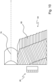
- the Figure 10 shows a further arrangement with a second light guide plate 64, which is less wide in the horizontal direction between right and left than the light guide plate of the Figure 8 , together with a projection lens system instead of a single first projection lens 24 or second projection lens 60.
- the light guide plate after the Figure 10 indicates at its transition between its radiation side and the side used for feeding in light. This also makes it possible to create narrow radiation sides, as the kinks require less space for a change in direction than curved transitions.
Landscapes
- Engineering & Computer Science (AREA)
- General Engineering & Computer Science (AREA)
- Physics & Mathematics (AREA)
- Microelectronics & Electronic Packaging (AREA)
- Optics & Photonics (AREA)
- Non-Portable Lighting Devices Or Systems Thereof (AREA)
Description
- Die vorliegende Erfindung betrifft einen Kraftfahrzeugscheinwerfer nach dem Oberbegriff des Anspruchs 1.
- Ein solcher Kraftfahrzeugscheinwerfer ist aus der
FR 3 079 597 A1 - Ferner ist aus der
DE 10 2018 113 768 A1 ein Projektionslichtmodul bekannt und weist ein erstes Projektionslichtmodul auf, das eine erste Halbleiterlichtquelle, eine erste Projektionslinse und eine erste Zusatzlichtquelle sowie eine erste Lichtleiterplatte aufweist. Die erste Projektionslinse weist eine erste optische Achse und eine erste Lichteintrittsfläche auf, die mit der ersten Zusatzlichtquelle durch die erste Lichtleiterplatte hindurch beleuchtbar ist. Dabei ist die erste Zusatzlichtquelle an einer Schmalseite der ersten Lichtleiterplatte so angeordnet, dass von der ersten Zusatzlichtquelle ausgehendes Licht quer zu der ersten optischen Achse in die erste Lichtleiterplatte eintritt. Die erste Lichtleiterplatte weist eine der ersten Projektionslinse zugewandte vordere Abstrahlseite und eine der vorderen Abstrahlseite gegenüberliegende hintere Umlenkseite sowie einen näher an der ersten optischen Achse liegenden ersten Teil und einen weiter von der optischen Achse entfernt liegenden zweiten Teil auf. Der erste Teil und der zweite Teil sind Bestandteile der ersten Lichtleiterplatte. - Zur Realisierung von Kraftfahrzeugscheinwerfern mit einem LED-Abblendlicht und einem LED-Fernlicht bzw. LED-Matrixfernlicht diese Scheinwerfer mehr und mehr mit jeweils einem AbblendlichtLED-Modul, das das volle Abblendlicht des Scheinwerfers erzeugt, und einem Matrixfernlichtmodul, das zusätzlich im Fernlichtfall die Matrixfunktion darstellt. Unter einer Matrixfunktion wird hier verstanden, dass die Fernlichtverteilung eine Mehrzahl von Matrixelementen in Form von Segmenten der Lichtverteilung aufweist, die sich individuell steuerbar abdunkeln lassen, um Blendungen anderer Verkehrsteilnehmer zu vermeiden und gleichzeitig mit hellen Segmenten eine gute Ausleuchtung der Fahrbahn zu erzielen.
- Bei Kraftfahrzeugscheinwerfern mit einem Projektionslichtmodul für Fernlicht und einem Projektionslichtmodul für Abblendlicht wird gewünscht, dass beide Projektionslinsen der Projektionslichtmodule auch dann leuchtend erscheinen, wenn nur das Abblendlicht eingeschaltet ist, um ein einheitliches Erscheinungsbild zwischen Teilfernlicht und Abblendlicht zu erzielen
- Zu diesem Zweck wurde bisher eine zusätzliche LED auf der LED-Platine des Matrixfernlichtmoduls verbaut und dessen Licht über zwei metallisierte Reflektoren auf die Linseneintrittsseite gelenkt. Die Anordnung der Reflektoren war dabei so gewählt, dass der Lichtpfad der Matrixfunktion nicht gestört wird und die Reflexionsfläche des zweiten Reflektors nahe der Abbildungsebene der Projektionslinse liegt.
- Werden die Matrixelemente der Fernlichtverteilung über den jeweiligen LEDs zugeordnete Sammellinsen, also mit einer refraktiven Vorsatzoptik, und deren Abbildung über die nachgeschaltete gemeinsame Projektionslinse erzeugt, läuft das zur Aufhellung der Projektionslinse dienende Zusatzlicht über zwei metallisierte Reflektoren.
- Dadurch kommt es zu einer anderen Lichtfarbe als beim Matrixlicht. Dies lässt sich auch durch eine geeignete Wahl der dazugehörigen LED, insbesondere deren zugehörige Farborte, nicht gänzlich kompensieren. Das beschriebene optische System der Linsenaufhellung des Fernlichtmoduls unterscheidet sich vor allem auch von dem des Abblendlichtmoduls. Hierdurch weicht die Lichtfarbe des Zusatzlichtes von der des Abblendlichtes ab.
- Des Weiteren gelingt durch die zwangsläufige geneigte Anordnung des zweiten Reflektors des bekannten Zusatzlichtes eine Annäherung an die Abbildungsebene der Projektionslinse nur unzureichend. Dies führt zu einem inhomogenen Erscheinungsbild der leuchtenden Linse.
- Nach der oben genannten
DE 10 2018 113 768 A1 wird auf der Höhe der Vorsatzoptik des Matrixlichtmoduls mittels einer Lichtleiterplatte eine homogene Leuchtdichte erzeugt. Dabei wird der Lichtleiter seitlich von jeweils einer auf der Matrixlicht-LED-Platine platzierten LED mit Zusatzlicht gespeist. Das innerhalb der Lichtleiterplatte propagierende Licht wird durch auf deren Rückseite angebrachte Prismen in Richtung der Projektionslinse gelenkt. Dabei gelingt eine homogene Ausleuchtung der Lichtleiterplatte. Dadurch und durch die Lage des Lichtleiters in der Bildebene der Projektionslinse wird bereits ein der Form der Projektionslinse entsprechendes homogenes Erscheinungsbild der Projektionslinse für den Betrachter erzielt, auch wenn die Projektionslinse für ihren eigentlichen Zweck, eine Scheinwerferlichtverteilung zu erzeugen, nicht komplett ausgeleuchtet wird. - Es hat sich überraschend gezeigt, dass die gekippte Anordnung die Homogenität der Ausleuchtung der ersten Projektionslinse mit Zusatzlicht weiter verbessert. Aufgabe der Erfindung ist es, ein noch einheitlicheres Erscheinungsbild zwischen Teilfernlicht und Abblendlicht zu erzielen.
- Diese Aufgabe wird mit dem Merkmalen von Anspruch 1 gelöst. Eine bevorzugte Ausgestaltung zeichnet sich dadurch aus, dass das erste Projektionslichtmodul ein Fernlichtmodul ist. Das Matrixfernlicht hat die Eigenschaft, dass sich das Erscheinungsbild der Linse in Abhängigkeit von der Lage der hellen und dunklen Matrixelemente ändert. Daher wirkt sich die Erfindung, die für ein gleichmäßigeres Erscheinungsbild sorgt, hier besonders vorteilhaft aus.
- Bevorzugt ist auch, dass der Kraftfahrzeugscheinwerfer ein zweites Projektionslichtmodul, das eine zweite Halbleiterlichtquelle, eine zweite Projektionslinse und eine zweite Zusatzlichtquelle sowie eine zweite Lichtleiterplatte aufweist, wobei die zweite Projektionslinse eine zweite optische Achse und eine zweite Lichteintrittsfläche aufweist, die mit der zweiten Zusatzlichtquelle durch die zweite Lichtleiterplatte hindurch beleuchtbar ist, wobei die zweite Zusatzlichtquelle an einer Schmalseite der zweiten Lichtleiterplatte so angeordnet ist, dass von der zweiten Zusatzlichtquelle ausgehendes Licht quer zu der zweiten optischen Achse in die zweite Lichtleiterplatte eintritt und die zweite Lichtleiterplatte eine der zweiten Projektionslinse zugewandte vordere Abstrahlseite und eine der vorderen Abstrahlseite gegenüberliegende hintere Umlenkseite sowie einen näher an der zweiten optischen Achse liegenden ersten Teil und einen weiter von der zweiten optischen Achse entfernt liegenden zweiten Teil aufweist, und dass die Lichtleiterplatte in einer verkippten Stellung angeordnet ist, in der sich der erste Teil der zweiten Lichtleiterplatte entlang der zweiten optischen Achse weiter von der zweiten Projektionslinse entfernt befindet als der zweite Teil der zweiten Lichtleiterplatte.
- Weiter ist bevorzugt, dass das zweite Projektionslichtmodul eine im Kraftfahrzeugscheinwerfer von hinten nach vorn verlaufende Spiegelblende aufweist und dass die Lichtleiterplatte unterhalb der Spiegelblende angeordnet ist.
- Durch diese Ausgestaltung wird ein Abblendlichtmodul mit verbesserter Ausleuchtung der Projektionslinse bereitgestellt. Auch für diese Ausgestaltung gilt, dass sich überraschend gezeigt hat, dass die gekippte Anordnung die Homogenität der Ausleuchtung der zweiten Projektionslinse mit Zusatzlicht weiter verbessert. Durch die Verwendung derselben Merkmale im Abblendlichtmodul wie im Fernlichtmodul lässt sich hier eine zusätzliche Homogenisierung und Angleichung der Lichtfarbe der Linsenausleuchtung der Abblendlichtlinse an die Linsenausleuchtung der Fernlichtlinse erzielen.
- Eine weitere bevorzugte Ausgestaltung zeichnet sich dadurch aus, dass die Lichtfarbe der Zusatzlichtquelle unveränderlich ist und sich von der Lichtfarbe des Fernlichtes und/oder des Abblendlichtes unterscheidet. Durch diese Ausgestaltung ergibt sich eine feste aber von der Lichtfarbe des Fernlichtes und/oder des Abblendlichtes bewusst verschieden farbige Ausleuchtung des restlichen farblosen Lichtleiters und somit eine entsprechend mehrfarbige Ausleuchtung der Projektionslinse.
- Eine weitere bevorzugte Ausgestaltung zeichnet sich dadurch aus, dass die erste Lichtleiterplatte und/oder die zweite Lichtleiterplatte wenigstens einen farbigen Bereich aufweist.
- Bevorzugt ist auch, dass der farbige Bereich ein Lichteintrittsbereich der im Übrigen farblos transparenten Lichtleiterplatte ist.
- Weiter ist bevorzugt, dass der farbige Bereich ein farbig beschichteter Lichteintrittsbereich der ansonsten farblosen Lichtleiterplatte ist.
- Diese Ausgestaltungen, bei denen die Lichtleiterplatte oder Teile dieser, insbesondere der Bereich der Einspeisung (2.1), aus einem farbig-transparenten Material ausgestaltet werden, haben den Effekt, dass eine erwünschte farbige Ausleuchtung der Projektionslinse(n) durch Speisung der Lichtleiterplatte(n) mit einer weißes Licht emittierenden LED erzielt werden kann. Damit wird eine Alternative zur Verwendung farbiger Lichtquellen bereitgestellt.
- Dann wäre diese Vorsatzoptik zwei farbig, als ein sogenanntes 2-Komponten-(2K)-Teil. Im Speziellem kann die Grenzfläche der beiden Komponenten zusammen mit der Eintrittsfläche hinsichtlich einer einheitlichen farbigen Ausleuchtung des restlichen Lichtleiters (2.2) optimiert sein.
- Eine weitere Variante anstelle einer zweifarbigen Lichtleiterplatte besteht in einer Beschichtung der Eintrittsfläche der ansonsten farblosen Lichtleiterplatte, deren optische Eigenschaften derart gestaltet ist, dass diese nur für Licht einer festen Farbe bzw. Wellenlänge transparent ist und sämtliche Licht anderer Farbe bzw. Wellenlängen absorbiert oder reflektiert.
- Bevorzugt ist auch, dass die Lichtfarbe der ersten und/oder zweiten Zusatzlichtquelle steuerbar veränderlich ist und sich von der Lichtfarbe des Fernlichtes und/oder des Abblendlichtes unterscheiden kann.
- Weiter ist bevorzugt, dass die erste und/oder zweite Zusatzlichtquelle individuell steuerbare, verschiedenfarbige Leuchtdioden aufweist.
- Eine zeitlich veränderte Farbe der Linsenausleuchtung, insbesondere eine zu dem Abblendlicht und dem Fernlicht bewusst verschiedene Hauptlichtfunktionen bewusst verschiedene Farbe, lässt sich mit dem oben genannten Stand der Technik nicht realisieren. Diese Einschränkung der möglichen Erscheinungsbilder, mit denen zum Beispiel ein farbiges Begrüßungslicht mit den Scheinwerfern erzeugbar ist, wird durch diese Ausgestaltung beseitigt.
- Eine weitere bevorzugte Ausgestaltung zeichnet sich dadurch aus, dass die individuell steuerbaren, verschiedenfarbigen Leuchtdioden eine rotes Licht emittierende Leuchtdiode, eine grünes Licht emittierende Leuchtdiode und eine blaues Licht emittierende Leuchtdiode umfassen.
- Eine Alternative zur erfindungsgemäßen Verwendung der Lichtleiterplatte könnte eine für beide Funktionen, also für die Funktion der Erzeugung einer Lichtverteilung und die Funktion der gleichmäßigen Ausleuchtung der Projektionslinsen könnte in der Verwendung einer für diese beiden Funktionen gemeinsamen Vorsatzoptik liegen.
- Weitere Vorteile ergeben sich aus der nachfolgenden Beschreibung, den Zeichnungen und den Unteransprüchen.
- Ausführungsbeispiele der Erfindung sind in den Zeichnungen dargestellt und werden in der nachfolgenden Beschreibung näher erläutert.
- Dabei zeigen, jeweils in schematischer Form:
- Figur 1
- einen Kraftfahrzeugscheinwerfer mit Angaben zu Anordnung im Raum;
- Figur 2
- einen vertikalen Schnitt durch einen Kraftfahrzeugscheinwerfer;
- Figur 3
- ein erstes Projektionslichtmodul von vorn;
- Figur 4
- ein zweites Projektionslichtmodul;
- Figur 5
- eine Vorderansicht des zweiten Projektionslichtmoduls; und
- Figur 6
- eine schematische Draufsicht auf eine RGB-LED;
- Figur 7
- eine Lichtleiterplatte, die ganz oder teilweise aus einem farbig-transparenten Material ausgestaltet ist.
- Figur 8
- eine Anordnung mit einer verkippt angeordneten ersten Lichtleiterplatte, die sich durch einen gleichmäßig gekrümmten Übergang von ihren Abstrahl- und Umlenkseiten in die zur Einspeisung des Zusatzlichtes dienenden seitlichen Schmalseiten auszeichnet;
- Figur 9
- eine Anordnung mit einer Lichtleiterplatte, die in Vertikalrichtung weniger hoch ist als die Lichtleiterplatte der
Figur 8 ; und - Figur 10
- eine weitere Anordnung mit einer Lichtleiterplatte, die in der zwischen rechts und links verlaufenden horizontalen Richtung weniger breit ist als die Lichtleiterplatte der
Figur 8 . - Im Einzelnen zeigt die
Figur 1 einen Kraftfahrzeugscheinwerfer 10 mit einer Hauptabstrahlrichtung 12, die nach vorne v weist. Die Angabe h kennzeichnet eine hintere Position, während die Angaben r und 1 eine rechte Seite und eine linke Seite und die Angaben o und u eine obere und eine untere Position kennzeichnen. Der Kraftfahrzeugscheinwerfer 10 weist ein erstes Projektionslichtmodul 14 und ein zweites Projektionslichtmodul 16 auf. Die Lage- und Positionsangaben vorne, hinten, rechts, links, oben und unten beziehen sich jeweils auf eine Orientierung des Kraftfahrzeugscheinwerfers im Raum bei seiner bestimmungsgemäßen Verwendung in einem Kraftfahrzeug. -
Figur 2 zeigt einen vertikalen und zwischen vorn v und hinten h verlaufenden Schnitt durch den Kraftfahrzeugscheinwerfer 10, der ein Gehäuse 18 aufweist, dessen Lichtaustrittsöffnung durch eine transparente Abdeckscheibe 20 abgedeckt wird. Das erste Projektionslichtmodul 14 weist eine erste Halbleiterlichtquelle 22, eine erste Projektionslinse 24 und eine erste Zusatzlichtquelle 26 sowie eine erste Lichtleiterplatte 28 auf. Die erste Projektionslinse 24 weist eine erste optische Achse 30 und eine erste Lichteintrittsfläche 32 auf. Die erste Lichteintrittsfläche 32 ist mit Zusatzlicht 34 der ersten Zusatzlichtquelle 26 durch die erste Lichtleiterplatte 28 hindurch beleuchtbar. Die erste Zusatzlichtquelle 26 ist an einer Schmalseite 36 der ersten Lichtleiterplatte 28 so angeordnet, dass von der ersten Zusatzlichtquelle 26 ausgehendes Zusatzlicht 34 quer (nämlich seitlich, insbesondere in rechts-links Richtung) zu der in vorn-hinten Richtung verlaufenden ersten optischen Achse 30 in die erste Lichtleiterplatte 28 eintritt und die erste Lichtleiterplatte 28 eine der ersten Projektionslinse 24 zugewandte erste vordere Abstrahlseite 38 und eine der ersten vorderen Abstrahlseite 38 gegenüberliegende erste hintere Umlenkseite 40 sowie einen näher an der ersten optischen Achse 30 liegenden ersten Teil 42 und einen weiter von der ersten optischen Achse 30 entfernt liegenden zweiten Teil 44 aufweist. Die erste Lichtleiterplatte 28 ist erfindungsgemäß in einer verkippten Stellung angeordnet, in der sich der erste Teil 42 der ersten Lichtleiterplatte 28 entlang der ersten optischen Achse 30 weiter von der ersten Projektionslinse 24 entfernt befindet als der zweite Teil 44 der ersten Lichtleiterplatte 28. Die Lichtleiterplatte ist insbesondere in dem Vertikalschnitt, in dem auch die erste optische Achse 30 liegt, nicht rechtwinklig zur ersten optischen Achse angeordnet. -
Figur 3 zeigt das erste Projektionslichtmodul 14 von vorn. In dieser Ausgestaltung sind zwei Zusatzlichtquellen 26 vorgesehen, von denen eine an einer rechten Schmalseite 36.r und eine an einer linken Schmalseite 36.1 angeordnet ist. Das von den Zusatzlichtquellen 26 ausgehende Zusatzlicht 34 tritt seitlich in die erste Lichtleiterplatte 28 ein und verteilt sich, auch durch interne Totalreflexionen, gleichmäßig in der ersten Lichtleiterplatte 28. An in der ersten hinteren Umlenkseite 40 der ersten Lichtleiterplatte 28 angeordneten Umlenkstrukturen wird das Zusatzlicht 34 so steil zur ersten vorderen Abstrahlseite 38 der ersten Lichtleiterplatte 28 umgelenkt, dass es dort gleichmäßig verteilt austritt. Durch in der ersten vorderen Abstrahlseite 38 angeordnete Streustrukturen 52 wird das ausgetretene Zusatzlicht 34 zumindest in vertikaler Richtung so gestreut, dass es die erste Lichteintrittsfläche 32 der ersten Projektionslinse 24 gleichmäßig verteilt ausleuchtet. - Das in den
Figuren 2 und 3 dargestellte erste Projektionslichtmodul 14 ist ein Fernlichtmodul. Das von der ersten Halbleiterlichtquelle 22 ausgehende Licht wird nicht von einer horizontalen Blende abgeschattet oder umgelenkt. - Die erste Halbleiterlichtquelle 22 des ersten Projektionslichtmoduls 14 weist n nebeneinander angeordnete LEDs auf, von denen jede genau einen und nur ihr zugeordneten ersten Vorsatzoptikabschnitt 56 einer ersten Vorsatzoptik 50 beleuchtet. Die Zahl der ersten Vorsatzoptikabschnitte 56 ist entsprechend ebenfalls gleich n. Die Zahl n ist hier gleich 6, ohne dass n auf diesen Wert beschränkt sein soll. Die einzelnen LEDs und die erste Zusatzlichtquelle 26 sind mit einem Steuergerät 58 des ersten Projektionslichtmoduls 14 individuell steuerbar. Die in der
Figur 3 sichtbaren Lichtaustrittsflächen der ersten Vorsatzoptikabschnitte 56 werden von der ersten Projektionslinse 24 nach vorn abgebildet, wobei die Bilder so angeordnet sind wie die Lichtaustrittsflächen der ersten Vorsatzoptikabschnitte 56. Durch Abdunkeln einzelner LEDs können damit Abschnitte der Fernlichtverteilung individuell abgedunkelt werden, um Blendungen anderer Verkehrsteilnehmer zu vermeiden. Das Steuergerät 58 verarbeitet dazu Signale einer Fahrzeugumfeldsensorik, z.B. einer Kamera und/oder Radarsensoren. - Bei sämtlichen Ausgestaltungen des ersten Projektionslichtmoduls 14 befindet sich der erste (obere) Teil 42 der ersten Lichtleiterplatte 28 dicht unterhalb der ersten Vorsatzoptikabschnitte 56 und in, bzw. in der Nähe der Abbildungsebene einer ersten Projektionslinse 24 bzw. eines Projektionslinsensystems. Daher gelingt eine homogene Ausleuchtung der ersten Projektionslinse 24, die als solche auch unter kleinen (z.B. kleiner als 5°) Betrachtungswinkeln zur ersten optischen Achse 30 der ersten Projektionslinse 24 sichtbar ist.
-
Figur 4 zeigt den Kraftfahrzeugscheinwerfer 10 mit einem zweiten Projektionslichtmodul 16. Das zweite Projektionslichtmodul 16 weist eine zweite Halbleiterlichtquelle 74, eine zweite Projektionslinse 60 und eine zweite Zusatzlichtquelle 62 sowie eine zweite Lichtleiterplatte 64 auf. Die zweite Projektionslinse 60 weist eine zweite optische Achse 66 und eine zweite Lichteintrittsfläche 54 auf, die mit der zweiten Zusatzlichtquelle 62 durch die zweite Lichtleiterplatte 64 hindurch beleuchtbar ist. Dabei ist die zweite Zusatzlichtquelle 62 an einer Schmalseite der zweiten Lichtleiterplatte 64 so angeordnet, dass von der zweiten Zusatzlichtquelle 62 ausgehendes Licht quer zu der zweiten optischen Achse 66 in die zweite Lichtleiterplatte 64 eintritt. Die zweite Lichtleiterplatte 64 weist eine der zweiten Projektionslinse 60 zugewandte zweite vordere Abstrahlseite 68 und eine der zweiten vorderen Abstrahlseite 68 gegenüberliegende zweite hintere Umlenkseite 70 sowie einen näher an der zweiten optischen Achse 66 liegenden ersten Teil 43 und einen weiter von der zweiten optischen Achse 66 entfernt liegenden zweiten Teil 45 auf. Die zweite Lichtleiterplatte 64 ist in einer verkippten Stellung angeordnet, in der sich der erste Teil 43 der zweiten Lichtleiterplatte 64 entlang der zweiten optischen Achse 66 weiter von der zweiten Projektionslinse 60 entfernt befindet als der zweite Teil 45 der zweiten Lichtleiterplatte 64. Die zweite Lichtleiterplatte 64 ist insbesondere in dem Vertikalschnitt, in dem auch die zweite optische Achse 66 liegt, nicht rechtwinklig zur zweiten optischen Achse 66 angeordnet. - Ein Unterschied zwischen den Gegenständen der
Figuren 2 und 3 auf der einen Seite und dem Gegenstand derFiguren 4 und 5 auf der anderen Seite besteht darin, dass das zweite Projektionslichtmodul 16 eine im Kraftfahrzeugscheinwerfer 10 von hinten nach vorn verlaufende Spiegelblende 72 aufweist und dass die zweite Lichtleiterplatte 64 unterhalb der Spiegelblende 72 angeordnet ist. - Die Spiegelblende 72 weist eine der zweiten Halbleiterlichtquelle 74 und der zweiten Vorsatzoptik 76 zugewandte spiegelnde Fläche auf, die sich von hinten nach vorn bis in den Fokalbereich der zweiten Vorsatzoptik 76 und der zweiten Projektionslinse 60 hinein erstreckt. Die zweite Vorsatzoptik 76 ist hier ein Halbschalenreflektor mit einer ellipsoiden Grundform. Die zweite Halbleiterlichtquelle ist in einem Brennpunkt des Halbschalenreflektors angeordnet. Ein zweiter Brennpunkt, bzw. Fokalbereich des Halbschalenreflektors wird von der Blendenkante 78 geschnitten. Die im Fokalbereich liegende Blendenkante 78 der Spiegelblende 72 wird von der zweiten Projektionslinse 60 als zwischen rechts und links verlaufende Hell-Dunkel-Grenze einer Abblendlichtverteilung abgebildet.
-
Figur 5 zeigt eine Vorderansicht des zweiten Projektionslichtmoduls 16 mit der zwischen rechts und links verlaufenden Blendenkante 78 der Spiegelblende 72, der oberhalb von der Spiegelblende 72 angeordneten zweiten Vorsatzoptik 76 und der unterhalb von der Spiegelblende 72 angeordneten zweiten Lichtleiterplatte 64. - In Bezug auf die Funktion und Details der zweiten Lichtleiterplatte 64 und der Zusatzlichterzeugung gilt weitgehend die Beschreibung der
Figuren 2 und 3 auch für dieFiguren 4 und 5 . - Alternativ zu der Verwendung eines Reflektors als zweite Vorsatzoptik 76 kann die zweite Vorsatzoptik 76 als Linse oder Lichtleiter ausgeführt sein. In einer Ausgestaltung bestehen die Lichtleiterplatten 28, 64 bevorzugt aus dem gleichen Lichtleitermaterial wie die Vorsatzoptiken. Dadurch wird mit den Lichtleiterplatten die gleiche Lichtfarbe erzielt wie mit den Vorsatzoptiken. Dies gilt jedenfalls dann, wenn z.B. die erste Zusatzlichtquelle Licht gleicher Lichtfarbe emittiert wie die erste Halbleiterlichtquelle.
- Weitere Ausgestaltungen sehen dagegen bewusst erzeugte Unterschiede zwischen den Lichtfarben, mit denen primär Lichtverteilungen erzeugt werden, und Lichtfarben, mit denen primär die Projektionslinsen zusätzlich mit dem Zusatzlicht gleichmäßig ausgeleuchtet werden, vor.
- Hierzu sieht man in einer bevorzugten Ausgestaltung die Verwendung von farbigen LEDs als Zusatzlichtquellen vor. Vorteilhafterweise weisen diese Zusatzlichtquellen jeweils drei dicht nebeneinander angeordnete LED-Chips R, G, B auf, die zusammen eine zweite Halbleiterlichtquelle 74 bilden. de.
-
Figur 6 zeigt eine Draufsicht auf eine solche Anordnung. Die Hauptabstrahlrichtung dieser Anordnung ist senkrecht zur Zeichnungsebene. Jeder dieser Chips R, G, B emittiert eine andere ihm fest zugeordnete Lichtfarbe, idealerweise rot, grün und blau. Durch den Betrieb der einzelnen LED-Chips R, G, B mit jeweils unterschiedlicher Helligkeit lässt sich die Farbe des von der Zusatzlichtquelle ausgesandten Lichtes und somit des Zusatzlichtes nach dem RGB-Farbmodell nahezu frei einstellen. Dazu werden die farbigen LEDs R, G, B von dem Steuergerät 58 gesteuert. Wie bereits allgemein für Licht der Zusatzlichtquellen beschrieben, gilt auch für das farbige Licht von RGB-LEDs R, G, B, dass dieses Licht in die Lichtleiterplatte eingespeist und durch eine Prismenstruktur an der Umlenkseite der Lichtleiterplatte 28, 64 in Richtung zu einer abbildenden Projektionslinse 24, 60 umgelenkt wird. Damit könnte zu Beispiel das Erscheinungsbild eines Kraftfahrzeugscheinwerfers 10 in das Erscheinungsbild einer Heckleuchte umgewandelt werden. Bei Rückwärtsfahrt könnte das Abblendlicht und das Fernlicht abgeschaltet werden, und die zugehörigen Projektionslinsen 24, 60 könnten vorübergehend rot ausgeleuchtet werden, um eine Schlusslichtfunktion und/oder eine Bremslichtfunktion zu erfüllen. -
Figur 7 zeigt, dass die Lichtleiterplatte 28 und/oder 64 ganz oder teilweise als Alternative zur Verwendung farbiger Lichtquellen aus einem farbig-transparenten Material ausgestaltet sein kann werden und diese Lichtleiterplatte dann mit einer weißen LED gespeist wird. Dies gilt insbesondere für den Bereich 80 der Einspeisung oder Teile davon. - Diese Alternative würde eine feste aber von der Lichtfarbe der Abblendlichtverteilung und/oder der Fernlichtverteilung bewusst verschiedene farbige Ausleuchtung der übrigen farblosen Lichtleiterplatte ergeben und somit zu einem entsprechend farbigen Zusatzlicht für die Ausleuchtung der Projektionslinsen 24, 60 führen.
- Eine solche Lichtleiterplatte 28, 64 wäre zweifarbig, was als ein sogenanntes 2-Komponenten-(2K)-Teil mit einem entsprechenden 2K-Spritzgussverfahren herstellbar ist. Im Speziellem kann die Grenzfläche der beiden dann farblich unterschiedlichen Komponenten der Lichtleiterplatte 28, 64 zusammen mit der Lichteintrittsfläche der Lichtleiterplatte 28, 64 hinsichtlich einer einheitlichen farbigen Ausleuchtung der übrigen Lichtleiterplatte optimiert sein.
- Eine weitere Variante anstelle einer zweifarbigen Lichtleiterplatte besteht in einer Beschichtung der Eintrittsfläche der ansonsten farblosen Lichtleiterplatte, deren optische Eigenschaften derart gestaltet ist, dass diese nur für Licht einer festen Farbe bzw. Wellenlänge transparent ist und sämtliche Licht anderer Farbe bzw. Wellenlängen absorbiert oder reflektiert.
- Die Lichtleiterplatte 28, 64 weist eine Schmalseite 36 auf, über die Licht einer Zusatzlichtquelle 26, 62 (Vergleiche
Figuren 2 bis 4 ) in die Lichtleiterplatte 28, 64 eingespeist wird. Die Schmalseite 36 schließt ein Einkoppelprisma ab, das einen trapezförmigen Querschnitt aufweist und sich über die Höhe des Prismas erstreckt. Die Schmalseite 36 bildet eine der beiden einander parallelen Flächen des Prismas. Die dazu parallele Fläche des Prismas bildet eine Übergangsfläche, mit welcher der Bereich 80 der Einspeisung, der hier mit dem Prisma identisch ist, in den Rest der Lichtleiterplatte übergeht. Das über den farbigen Bereich 80 der Einspeisung in die Lichtleiterplatte eingespeiste Licht der Zusatzlichtquelle erfährt an den schräg zueinander stehenden Begrenzungsflächen des prismatischen Bereichs 31 den Öffnungswinkel des eingespeisten Lichtes reduzierende interne Totalreflexionen. Anschließend wird dieses Licht an einem bevorzugt gekrümmten Randbereich in einen Bereich der Leiterplatte umgelenkt, der eine ebene, gekippt stehende Mittelfläche aufweist. Dieser Bereich wird nach hinten durch eine Umlenkfläche und nach vorn durch eine Abstrahlfläche begrenzt. In der Umlenkfläche sind Umlenkelemente angeordnet, die zum Beispiel vertikal verlaufende Kanten aufweisen, die schräge Prismenflächen begrenzen. Die Umlenkelemente sind so geformt, auf sie aus dem Inneren der Lichtleiterplatte einfallendes Licht der Zusatzlichtquelle durch interne Totalreflexionen so steil zur vorderen Abstrahlfläche umgelenkt wird, dass es dort aus der Lichtleiterplatte austritt, wobei das Licht bevorzugt schräg nach oben abgestrahlt wird. In der Abstrahlfläche sind bevorzugt walzenabschnittsförmige Umlenkelemente angeordnet, die das aus der Abstrahlfläche austretende Licht so breit verteilen, dass es die Lichteintrittsfläche der im Strahlengang folgenden Projektionslinse homogen ausleuchtet. Die Walzenabschnitte erstrecken sich bevorzugt von der als Lichteintrittsseite dienenden Schmalseite quer über die ganze Breite der Abstrahlfläche. Dabei wechseln sich bevorzugt konvexe Walzenabschnitte und konkave Walzenabschnitte ab. Die Mantellinien der Walzenabschnitte verlaufen dabei parallel zueinander. In der Abstrahlfläche verlaufen die Mantellinien quer zur optischen Achse zwischen einer linken und einer rechten Position. Die Kanten der in der Umlenkfläche angeordneten Umlenkelemente verlaufen dagegen bevorzugt zwischen einer oberen und einer unteren Position, so dass die Umlenkelemente und die Walzenabschnitte quer zueinander verlaufen. -
Figur 8 zeigt eine Anordnung aus einer ersten Vorsatzoptik 50, einer verkippt angeordneten ersten Lichtleiterplatte 28 und einer ersten Zusatzlichtquelle 26 sowie einer ersten Projektionslinse. Die erste Lichtleiterplatte 28 zeichnet sich durch einen gleichmäßig gekrümmten Übergang von ihren Abstrahl- und Umlenkseiten in die zur Einspeisung des Zusatzlichtes dienenden seitlichen Schmalseiten 36 aus. Die zur Einspeisung des Zusatzlichtes dienende Schmalseite 36 liegt bevorzugt in der Lichteintrittsebene der Vorsatzoptik 76, 50. In diesem Fall können die Zusatzlichtquelle(n) und die zur Erzeugung der Scheinwerferlichtverteilungen dienenden LEDs auf derselben ebenen und starren Leiterplatte angeordnet sein. Dies gilt analog für dieFiguren 9 und10 .Figur 9 zeigt eine Anordnung mit einer Lichtleiterplatte, die in Vertikalrichtung weniger hoch ist als die Lichtleiterplatte derFigur 8 , und dieFigur 10 zeigt eine weitere Anordnung mit einer zweiten Lichtleiterplatte 64, die in der zwischen rechts und links verlaufenden horizontalen Richtung weniger breit ist als die Lichtleiterplatte derFigur 8 , zusammen mit einem Projektionslinsensystem an Stelle einer einzelnen ersten Projektionslinse 24 oder zweiten Projektionslinse 60. Die Lichtleiterplatte nach derFigur 10 weist an ihrem Übergang zwischen ihrer Abstrahlseite und ihrer zur Lichteinspeisung dienenden Seite einen Knick auf. Damit können auch schmale Abstrahlseiten verwirklicht werden, da die Knicke bezüglich eines Richtungswechsels weniger Platz brauchen als gekrümmte Übergänge.
Claims (11)
- Kraftfahrzeugscheinwerfer (10) mit einem ersten Projektionslichtmodul (14), das eine erste Halbleiterlichtquelle (22), eine erste Projektionslinse (24) und eine erste Zusatzlichtquelle (26) sowie eine erste Lichtleiterplatte (28) aufweist, wobei die erste Projektionslinse (24) eine erste optische Achse (30) und eine erste Lichteintrittsfläche (32) aufweist, die mit der ersten Zusatzlichtquelle (26) durch die erste Lichtleiterplatte (28) hindurch beleuchtbar ist, wobei die erste Zusatzlichtquelle (26) an einer Schmalseite (36) der ersten Lichtleiterplatte (28) so angeordnet ist, dass von der ersten Zusatzlichtquelle (26) ausgehendes Licht quer zu der ersten optischen Achse (30) in die erste Lichtleiterplatte (28) eintritt und die erste Lichtleiterplatte (28) eine der ersten Projektionslinse (24) zugewandte vordere Abstrahlseite (38) und eine der ersten vorderen Abstrahlseite (38) gegenüberliegende erste hintere Umlenkseite (40) sowie einen näher an der ersten optischen Achse (30) liegenden ersten Teil (42) und einen weiter von der ersten optischen Achse (30) entfernt liegenden zweiten Teil (44) aufweist, wobei die erste Lichtleiterplatte (28) in einer verkippten Stellung angeordnet ist, in der sich der erste Teil (42) der ersten Lichtleiterplatte (28) entlang der ersten optischen Achse (30) weiter von der ersten Projektionslinse (24) entfernt befindet als der zweite Teil (44) der ersten Lichtleiterplatte (28), dadurch gekennzeichnet, dass an in der ersten hinteren Umlenkseite (40) der ersten Lichtleiterplatte (28) angeordneten Umlenkstrukturen das Zusatzlicht (34) so steil zur ersten vorderen Abstrahlseite (38) der ersten Lichtleiterplatte (28) umgelenkt wird, dass es dort gleichmäßig verteilt austritt, und dass das ausgetretene Zusatzlicht (34) durch in der ersten vorderen Abstrahlseite (38) angeordnete Streustrukturen (52) zumindest in vertikaler Richtung so gestreut wird, dass es die erste Lichteintrittsfläche (32) der ersten Projektionslinse (24) gleichmäßig verteilt ausleuchtet.
- Kraftfahrzeugscheinwerfer (10) nach Anspruch 1, dadurch gekennzeichnet, dass das erste Projektionslichtmodul (14) ein Fernlichtmodul ist.
- Kraftfahrzeugscheinwerfer (10) nach Anspruch 1, gekennzeichnet durch ein zweites Projektionslichtmodul (16), das eine zweite Halbleiterlichtquelle (74), eine zweite Projektionslinse (60) und eine zweite Zusatzlichtquelle (62) sowie eine zweite Lichtleiterplatte (64) aufweist, wobei die zweite Projektionslinse (60) eine zweite optische Achse (66) und eine zweite Lichteintrittsfläche (54) aufweist, die mit der zweiten Zusatzlichtquelle (62) durch die zweite Lichtleiterplatte (64) hindurch beleuchtbar ist, wobei die zweite Zusatzlichtquelle (62) an einer Schmalseite der zweiten Lichtleiterplatte (64) so angeordnet ist, dass von der zweiten Zusatzlichtquelle (62) ausgehendes Licht quer zu der zweiten optischen Achse (66) in die zweite Lichtleiterplatte (64) eintritt und die zweite Lichtleiterplatte (64) eine der zweiten Projektionslinse (60) zugewandte zweite vordere Abstrahlseite (68) und eine der zweiten vorderen Abstrahlseite (68) gegenüberliegende zweite hintere Umlenkseite (70) sowie einen näher an der zweiten optischen Achse (66) liegenden ersten Teil (43) und einen weiter von der zweiten optischen Achse (66) entfernt liegenden zweiten Teil (45) aufweist, und dass die zweite Lichtleiterplatte (64) in einer verkippten Stellung angeordnet ist, in der sich der erste Teil (43) der zweiten Lichtleiterplatte (64) entlang der zweiten optischen Achse (66) weiter von der zweiten Projektionslinse (60) entfernt befindet als der zweite Teil (45) der zweiten Lichtleiterplatte (64).
- Kraftfahrzeugscheinwerfer (10) nach Anspruch 3, dadurch gekennzeichnet, dass das zweite Projektionslichtmodul (16) eine im Kraftfahrzeugscheinwerfer (10) von hinten nach vorn verlaufende Spiegelblende (72) aufweist und dass die zweite Lichtleiterplatte (64) unterhalb der Spiegelblende (72) angeordnet ist.
- Kraftfahrzeugscheinwerfer (10) nach Anspruch 3, dadurch gekennzeichnet, dass die erste Lichtleiterplatte (28) und/oder die zweite Lichtleiterplatte (64) wenigstens einen farbigen Bereich aufweist.
- Kraftfahrzeugscheinwerfer (10) nach Anspruch 5, dadurch gekennzeichnet, dass der farbige Bereich ein Lichteintrittsbereich der im Übrigen farblos transparenten Lichtleiterplatte ist.
- Kraftfahrzeugscheinwerfer (10) nach Anspruch 5, dadurch gekennzeichnet, dass der farbige Bereich ein farbig beschichteter Lichteintrittsbereich der ansonsten farblosen Lichtleiterplatte ist.
- Kraftfahrzeugscheinwerfer (10) nach einem der vorhergehenden Ansprüche, dadurch gekennzeichnet, dass die Lichtfarbe der ersten Zusatzlichtquelle (26) unveränderlich ist und sich von der Lichtfarbe eines Fernlichtes und/oder eines Abblendlichtes unterscheidet.
- Kraftfahrzeugscheinwerfer (10) nach einem der Ansprüche 3 bis 7, dadurch gekennzeichnet, dass die Lichtfarbe der ersten Zusatzlichtquelle (26) und/oder zweiten Zusatzlichtquelle (62) steuerbar veränderlich ist und sich von der Lichtfarbe eines Fernlichtes und/oder eines Abblendlichtes unterscheiden kann.
- Kraftfahrzeugscheinwerfer (10) nach Anspruch 9, dadurch gekennzeichnet, dass die erste Zusatzlichtquelle (26) und/oder zweite Zusatzlichtquelle (62) individuell steuerbare, verschiedenfarbige Leuchtdioden (R, G, B) aufweist.
- Kraftfahrzeugscheinwerfer (10) nach Anspruch 10, dadurch gekennzeichnet, dass die individuell steuerbaren, verschiedenfarbigen Leuchtdioden eine rotes Licht emittierende Leuchtdiode (R), eine grünes Licht emittierende Leuchtdiode (G) und eine blaues Licht emittierende Leuchtdiode (B) umfassen.
Applications Claiming Priority (1)
| Application Number | Priority Date | Filing Date | Title |
|---|---|---|---|
| DE102020119195.2A DE102020119195A1 (de) | 2020-07-21 | 2020-07-21 | Kraftfahrzeugscheinwerfer mit Projektionslichtmodulen |
Publications (2)
| Publication Number | Publication Date |
|---|---|
| EP3943809A1 EP3943809A1 (de) | 2022-01-26 |
| EP3943809B1 true EP3943809B1 (de) | 2025-01-15 |
Family
ID=76999661
Family Applications (1)
| Application Number | Title | Priority Date | Filing Date |
|---|---|---|---|
| EP21186577.9A Active EP3943809B1 (de) | 2020-07-21 | 2021-07-20 | Kraftfahrzeugscheinwerfer mit projektionslichtmodulen |
Country Status (2)
| Country | Link |
|---|---|
| EP (1) | EP3943809B1 (de) |
| DE (1) | DE102020119195A1 (de) |
Families Citing this family (1)
| Publication number | Priority date | Publication date | Assignee | Title |
|---|---|---|---|---|
| CZ202272A3 (cs) | 2022-02-15 | 2023-08-23 | Hella Autotechnik Nova, S.R.O. | Přední světlomet pro automobil |
Family Cites Families (8)
| Publication number | Priority date | Publication date | Assignee | Title |
|---|---|---|---|---|
| DE102010046021A1 (de) * | 2010-09-18 | 2012-03-22 | Automotive Lighting Reutlingen Gmbh | Kraftfahrzeugscheinwerfer mit einem Mehrfunktions-Projektionsmodul |
| DE102011076621B4 (de) | 2011-05-27 | 2017-03-02 | Automotive Lighting Reutlingen Gmbh | Beleuchtungseinrichtung für ein Kraftfahrzeug |
| JP2012256491A (ja) | 2011-06-08 | 2012-12-27 | Stanley Electric Co Ltd | 車両用灯具ユニット |
| EP3379139B1 (de) * | 2015-11-20 | 2025-01-22 | Koito Manufacturing Co., Ltd. | Lampenfassung |
| KR102405436B1 (ko) * | 2017-09-28 | 2022-06-07 | 에스엘 주식회사 | 차량용 램프 |
| CN207674345U (zh) * | 2018-01-19 | 2018-07-31 | 上海小糸车灯有限公司 | 聚光器和车灯模组 |
| FR3079597B1 (fr) * | 2018-03-28 | 2020-10-02 | Valeo Vision | Module optique pour vehicule automobile |
| DE102018113768A1 (de) | 2018-06-08 | 2019-12-12 | Automotive Lighting Reutlingen Gmbh | Kraftfahrzeugscheinwerfer mit mindestens zwei Lichtmodulen |
-
2020
- 2020-07-21 DE DE102020119195.2A patent/DE102020119195A1/de active Pending
-
2021
- 2021-07-20 EP EP21186577.9A patent/EP3943809B1/de active Active
Also Published As
| Publication number | Publication date |
|---|---|
| EP3943809A1 (de) | 2022-01-26 |
| DE102020119195A1 (de) | 2022-01-27 |
Similar Documents
| Publication | Publication Date | Title |
|---|---|---|
| DE69205858T2 (de) | Verbessertes zentralisiertes Beleuchtungssystem für Kraftfahrzeuge. | |
| EP2799761B1 (de) | Lichtmodul für einen kraftfahrzeugscheinwerfer | |
| DE10237262B4 (de) | Fahrzeugleuchte mit einer LED-Lichtquelle und gleichmäßiger Helligkeit | |
| DE102010056313C5 (de) | Beleuchtungseinrichtung eines Kraftfahrzeugs | |
| EP2784376B1 (de) | Kraftfahrzeugleuchte für dynamische Leuchtenfunktionen | |
| DE102017206325A1 (de) | Fahrzeugleuchte und Fahrzeug mit einer solchen | |
| DE112017004923B4 (de) | Lichtführungselement, Lichtführungseinheit und Beleuchtungsvorrichtung | |
| DE102017105838B4 (de) | Beleuchtungseinrichtung eines Kraftfahrzeugs mit einer Lichtleiteranordnung | |
| DE102017205010A1 (de) | Fahrzeugleuchte und Fahrzeug mit einer solchen | |
| EP2754948A2 (de) | Lichtmodul für einen Kraftfahrzeugscheinwerfer, der zur Erzeugung streifenförmiger Lichtverteilungen eingerichtet ist | |
| EP2338732A1 (de) | Kraftfahrzeugbeleuchtungseinrichtung mit einem Lichtleiter und verschiedenfarbigen Lichtquellen | |
| AT16685U1 (de) | Direktstrahlende LED-Leuchte mit Entblendungsoptik | |
| DE10239280A1 (de) | LED-Fahrzeuglampe | |
| EP3699486B1 (de) | Scheinwerfer mit einer mehrzahl von halbleiterlichtquellen und einem einstückigen primäroptikfeld | |
| DE102018113768A1 (de) | Kraftfahrzeugscheinwerfer mit mindestens zwei Lichtmodulen | |
| EP3210827A1 (de) | Leuchte für kraftfahrzeuge | |
| DE102011014113A1 (de) | Transparente Optik einer Beleuchtungseinrichtung eines Kraftfahrzeugs | |
| EP2500754B1 (de) | Beleuchtungseinrichtung für Kraftfahrzeug | |
| DE102022107679B4 (de) | Leuchte für ein Fahrzeug | |
| DE4112194C2 (de) | Kraftfahrzeugscheinwerfereinheit | |
| DE102013210257A1 (de) | Vorsatzoptik für eine Lichtquelle | |
| DE102015204735B4 (de) | Lichtleiterelement einer Kraftfahrzeug-Beleuchtungseinrichtung und Kraftfahrzeug-Beleuchtungseinrichtung mit einem solchen Lichtleiterelement | |
| DE112019004405T5 (de) | Optisches Element einer Fahrzeugleuchte, Fahrzeugleuchtenmodul, Fahrzeug-Scheinwerfer und Fahrzeug | |
| EP3943809A1 (de) | Kraftfahrzeugscheinwerfer mit projektionslichtmodulen | |
| DE102012215124B4 (de) | Beleuchtungseinrichtung mit mehreren Lichtquellen und Lichtleitkörpern sowie einem Reflektor |
Legal Events
| Date | Code | Title | Description |
|---|---|---|---|
| PUAI | Public reference made under article 153(3) epc to a published international application that has entered the european phase |
Free format text: ORIGINAL CODE: 0009012 |
|
| STAA | Information on the status of an ep patent application or granted ep patent |
Free format text: STATUS: THE APPLICATION HAS BEEN PUBLISHED |
|
| AK | Designated contracting states |
Kind code of ref document: A1 Designated state(s): AL AT BE BG CH CY CZ DE DK EE ES FI FR GB GR HR HU IE IS IT LI LT LU LV MC MK MT NL NO PL PT RO RS SE SI SK SM TR |
|
| STAA | Information on the status of an ep patent application or granted ep patent |
Free format text: STATUS: REQUEST FOR EXAMINATION WAS MADE |
|
| 17P | Request for examination filed |
Effective date: 20220726 |
|
| RBV | Designated contracting states (corrected) |
Designated state(s): AL AT BE BG CH CY CZ DE DK EE ES FI FR GB GR HR HU IE IS IT LI LT LU LV MC MK MT NL NO PL PT RO RS SE SI SK SM TR |
|
| GRAP | Despatch of communication of intention to grant a patent |
Free format text: ORIGINAL CODE: EPIDOSNIGR1 |
|
| STAA | Information on the status of an ep patent application or granted ep patent |
Free format text: STATUS: GRANT OF PATENT IS INTENDED |
|
| INTG | Intention to grant announced |
Effective date: 20240809 |
|
| GRAS | Grant fee paid |
Free format text: ORIGINAL CODE: EPIDOSNIGR3 |
|
| GRAA | (expected) grant |
Free format text: ORIGINAL CODE: 0009210 |
|
| STAA | Information on the status of an ep patent application or granted ep patent |
Free format text: STATUS: THE PATENT HAS BEEN GRANTED |
|
| AK | Designated contracting states |
Kind code of ref document: B1 Designated state(s): AL AT BE BG CH CY CZ DE DK EE ES FI FR GB GR HR HU IE IS IT LI LT LU LV MC MK MT NL NO PL PT RO RS SE SI SK SM TR |
|
| RAP3 | Party data changed (applicant data changed or rights of an application transferred) |
Owner name: MARELLI GERMANY GMBH |
|
| REG | Reference to a national code |
Ref country code: CH Ref legal event code: EP Ref country code: GB Ref legal event code: FG4D Free format text: NOT ENGLISH |
|
| REG | Reference to a national code |
Ref country code: DE Ref legal event code: R096 Ref document number: 502021006419 Country of ref document: DE |
|
| REG | Reference to a national code |
Ref country code: CH Ref legal event code: PK Free format text: BERICHTIGUNGEN |
|
| REG | Reference to a national code |
Ref country code: IE Ref legal event code: FG4D Free format text: LANGUAGE OF EP DOCUMENT: GERMAN |
|
| REG | Reference to a national code |
Ref country code: CH Ref legal event code: PK Free format text: BERICHTIGUNGEN |
|
| RIN2 | Information on inventor provided after grant (corrected) |
Inventor name: ARTIGOU, XAVIER Inventor name: AUSTERSCHULTE, ARMIN Inventor name: ZIEGLER, PATRICK Inventor name: STRAHL-SCHAEFER, STEPHANIE Inventor name: LOEHLE, ANJA Inventor name: VOGT, HENNING |
|
| RIN2 | Information on inventor provided after grant (corrected) |
Inventor name: ARTIGOU, XAVIER Inventor name: AUSTERSCHULTE, ARMIN Inventor name: ZIEGLER, PATRICK Inventor name: STRAHL-SCHAEFER, STEPHANIE Inventor name: LOEHLE, ANJA Inventor name: DR. VOGT, HENNING |
|
| P01 | Opt-out of the competence of the unified patent court (upc) registered |
Free format text: CASE NUMBER: APP_7369/2025 Effective date: 20250213 |
|
| REG | Reference to a national code |
Ref country code: NL Ref legal event code: MP Effective date: 20250115 |
|
| PG25 | Lapsed in a contracting state [announced via postgrant information from national office to epo] |
Ref country code: NL Free format text: LAPSE BECAUSE OF FAILURE TO SUBMIT A TRANSLATION OF THE DESCRIPTION OR TO PAY THE FEE WITHIN THE PRESCRIBED TIME-LIMIT Effective date: 20250115 |
|
| PG25 | Lapsed in a contracting state [announced via postgrant information from national office to epo] |
Ref country code: RS Free format text: LAPSE BECAUSE OF FAILURE TO SUBMIT A TRANSLATION OF THE DESCRIPTION OR TO PAY THE FEE WITHIN THE PRESCRIBED TIME-LIMIT Effective date: 20250415 |
|
| PG25 | Lapsed in a contracting state [announced via postgrant information from national office to epo] |
Ref country code: FI Free format text: LAPSE BECAUSE OF FAILURE TO SUBMIT A TRANSLATION OF THE DESCRIPTION OR TO PAY THE FEE WITHIN THE PRESCRIBED TIME-LIMIT Effective date: 20250115 |
|
| PG25 | Lapsed in a contracting state [announced via postgrant information from national office to epo] |
Ref country code: PL Free format text: LAPSE BECAUSE OF FAILURE TO SUBMIT A TRANSLATION OF THE DESCRIPTION OR TO PAY THE FEE WITHIN THE PRESCRIBED TIME-LIMIT Effective date: 20250115 |
|
| PG25 | Lapsed in a contracting state [announced via postgrant information from national office to epo] |
Ref country code: ES Free format text: LAPSE BECAUSE OF FAILURE TO SUBMIT A TRANSLATION OF THE DESCRIPTION OR TO PAY THE FEE WITHIN THE PRESCRIBED TIME-LIMIT Effective date: 20250115 |
|
| REG | Reference to a national code |
Ref country code: LT Ref legal event code: MG9D |
|
| PG25 | Lapsed in a contracting state [announced via postgrant information from national office to epo] |
Ref country code: IS Free format text: LAPSE BECAUSE OF FAILURE TO SUBMIT A TRANSLATION OF THE DESCRIPTION OR TO PAY THE FEE WITHIN THE PRESCRIBED TIME-LIMIT Effective date: 20250515 Ref country code: NO Free format text: LAPSE BECAUSE OF FAILURE TO SUBMIT A TRANSLATION OF THE DESCRIPTION OR TO PAY THE FEE WITHIN THE PRESCRIBED TIME-LIMIT Effective date: 20250415 |
|
| PG25 | Lapsed in a contracting state [announced via postgrant information from national office to epo] |
Ref country code: HR Free format text: LAPSE BECAUSE OF FAILURE TO SUBMIT A TRANSLATION OF THE DESCRIPTION OR TO PAY THE FEE WITHIN THE PRESCRIBED TIME-LIMIT Effective date: 20250115 |
|
| PG25 | Lapsed in a contracting state [announced via postgrant information from national office to epo] |
Ref country code: PT Free format text: LAPSE BECAUSE OF FAILURE TO SUBMIT A TRANSLATION OF THE DESCRIPTION OR TO PAY THE FEE WITHIN THE PRESCRIBED TIME-LIMIT Effective date: 20250515 Ref country code: LV Free format text: LAPSE BECAUSE OF FAILURE TO SUBMIT A TRANSLATION OF THE DESCRIPTION OR TO PAY THE FEE WITHIN THE PRESCRIBED TIME-LIMIT Effective date: 20250115 |
|
| PGFP | Annual fee paid to national office [announced via postgrant information from national office to epo] |
Ref country code: FR Payment date: 20250620 Year of fee payment: 5 |
|
| PG25 | Lapsed in a contracting state [announced via postgrant information from national office to epo] |
Ref country code: GR Free format text: LAPSE BECAUSE OF FAILURE TO SUBMIT A TRANSLATION OF THE DESCRIPTION OR TO PAY THE FEE WITHIN THE PRESCRIBED TIME-LIMIT Effective date: 20250416 Ref country code: BG Free format text: LAPSE BECAUSE OF FAILURE TO SUBMIT A TRANSLATION OF THE DESCRIPTION OR TO PAY THE FEE WITHIN THE PRESCRIBED TIME-LIMIT Effective date: 20250115 |
|
| PG25 | Lapsed in a contracting state [announced via postgrant information from national office to epo] |
Ref country code: SE Free format text: LAPSE BECAUSE OF FAILURE TO SUBMIT A TRANSLATION OF THE DESCRIPTION OR TO PAY THE FEE WITHIN THE PRESCRIBED TIME-LIMIT Effective date: 20250115 |
|
| PG25 | Lapsed in a contracting state [announced via postgrant information from national office to epo] |
Ref country code: SM Free format text: LAPSE BECAUSE OF FAILURE TO SUBMIT A TRANSLATION OF THE DESCRIPTION OR TO PAY THE FEE WITHIN THE PRESCRIBED TIME-LIMIT Effective date: 20250115 |
|
| PG25 | Lapsed in a contracting state [announced via postgrant information from national office to epo] |
Ref country code: DK Free format text: LAPSE BECAUSE OF FAILURE TO SUBMIT A TRANSLATION OF THE DESCRIPTION OR TO PAY THE FEE WITHIN THE PRESCRIBED TIME-LIMIT Effective date: 20250115 |
|
| PG25 | Lapsed in a contracting state [announced via postgrant information from national office to epo] |
Ref country code: IT Free format text: LAPSE BECAUSE OF FAILURE TO SUBMIT A TRANSLATION OF THE DESCRIPTION OR TO PAY THE FEE WITHIN THE PRESCRIBED TIME-LIMIT Effective date: 20250115 |
|
| REG | Reference to a national code |
Ref country code: DE Ref legal event code: R097 Ref document number: 502021006419 Country of ref document: DE |
|
| PGFP | Annual fee paid to national office [announced via postgrant information from national office to epo] |
Ref country code: AT Payment date: 20251020 Year of fee payment: 5 |
|
| PG25 | Lapsed in a contracting state [announced via postgrant information from national office to epo] |
Ref country code: CZ Free format text: LAPSE BECAUSE OF FAILURE TO SUBMIT A TRANSLATION OF THE DESCRIPTION OR TO PAY THE FEE WITHIN THE PRESCRIBED TIME-LIMIT Effective date: 20250115 Ref country code: EE Free format text: LAPSE BECAUSE OF FAILURE TO SUBMIT A TRANSLATION OF THE DESCRIPTION OR TO PAY THE FEE WITHIN THE PRESCRIBED TIME-LIMIT Effective date: 20250115 |
|
| PG25 | Lapsed in a contracting state [announced via postgrant information from national office to epo] |
Ref country code: RO Free format text: LAPSE BECAUSE OF FAILURE TO SUBMIT A TRANSLATION OF THE DESCRIPTION OR TO PAY THE FEE WITHIN THE PRESCRIBED TIME-LIMIT Effective date: 20250115 |
|
| PG25 | Lapsed in a contracting state [announced via postgrant information from national office to epo] |
Ref country code: SK Free format text: LAPSE BECAUSE OF FAILURE TO SUBMIT A TRANSLATION OF THE DESCRIPTION OR TO PAY THE FEE WITHIN THE PRESCRIBED TIME-LIMIT Effective date: 20250115 |
|
| PLBE | No opposition filed within time limit |
Free format text: ORIGINAL CODE: 0009261 |
|
| STAA | Information on the status of an ep patent application or granted ep patent |
Free format text: STATUS: NO OPPOSITION FILED WITHIN TIME LIMIT |
|
| REG | Reference to a national code |
Ref country code: CH Ref legal event code: L10 Free format text: ST27 STATUS EVENT CODE: U-0-0-L10-L00 (AS PROVIDED BY THE NATIONAL OFFICE) Effective date: 20251126 |
|
| 26N | No opposition filed |
Effective date: 20251016 |
|
| REG | Reference to a national code |
Ref country code: CH Ref legal event code: H13 Free format text: ST27 STATUS EVENT CODE: U-0-0-H10-H13 (AS PROVIDED BY THE NATIONAL OFFICE) Effective date: 20260224 |
|
| PG25 | Lapsed in a contracting state [announced via postgrant information from national office to epo] |
Ref country code: LU Free format text: LAPSE BECAUSE OF NON-PAYMENT OF DUE FEES Effective date: 20250720 |
|
| GBPC | Gb: european patent ceased through non-payment of renewal fee |
Effective date: 20250720 |
|
| REG | Reference to a national code |
Ref country code: BE Ref legal event code: MM Effective date: 20250731 |
|
| PG25 | Lapsed in a contracting state [announced via postgrant information from national office to epo] |
Ref country code: GB Free format text: LAPSE BECAUSE OF NON-PAYMENT OF DUE FEES Effective date: 20250720 |
|
| PGFP | Annual fee paid to national office [announced via postgrant information from national office to epo] |
Ref country code: DE Payment date: 20260115 Year of fee payment: 5 |
|
| PG25 | Lapsed in a contracting state [announced via postgrant information from national office to epo] |
Ref country code: BE Free format text: LAPSE BECAUSE OF NON-PAYMENT OF DUE FEES Effective date: 20250731 |
|
| PG25 | Lapsed in a contracting state [announced via postgrant information from national office to epo] |
Ref country code: CH Free format text: LAPSE BECAUSE OF NON-PAYMENT OF DUE FEES Effective date: 20250731 |