EP3943765A1 - Sliding component - Google Patents
Sliding component Download PDFInfo
- Publication number
- EP3943765A1 EP3943765A1 EP20777157.7A EP20777157A EP3943765A1 EP 3943765 A1 EP3943765 A1 EP 3943765A1 EP 20777157 A EP20777157 A EP 20777157A EP 3943765 A1 EP3943765 A1 EP 3943765A1
- Authority
- EP
- European Patent Office
- Prior art keywords
- groove portion
- introduction groove
- dynamic pressure
- pressure generation
- sliding component
- Prior art date
- Legal status (The legal status is an assumption and is not a legal conclusion. Google has not performed a legal analysis and makes no representation as to the accuracy of the status listed.)
- Pending
Links
Images





Classifications
-
- F—MECHANICAL ENGINEERING; LIGHTING; HEATING; WEAPONS; BLASTING
- F16—ENGINEERING ELEMENTS AND UNITS; GENERAL MEASURES FOR PRODUCING AND MAINTAINING EFFECTIVE FUNCTIONING OF MACHINES OR INSTALLATIONS; THERMAL INSULATION IN GENERAL
- F16J—PISTONS; CYLINDERS; SEALINGS
- F16J15/00—Sealings
- F16J15/16—Sealings between relatively-moving surfaces
- F16J15/34—Sealings between relatively-moving surfaces with slip-ring pressed against a more or less radial face on one member
- F16J15/3404—Sealings between relatively-moving surfaces with slip-ring pressed against a more or less radial face on one member and characterised by parts or details relating to lubrication, cooling or venting of the seal
- F16J15/3408—Sealings between relatively-moving surfaces with slip-ring pressed against a more or less radial face on one member and characterised by parts or details relating to lubrication, cooling or venting of the seal at least one ring having an uneven slipping surface
- F16J15/3412—Sealings between relatively-moving surfaces with slip-ring pressed against a more or less radial face on one member and characterised by parts or details relating to lubrication, cooling or venting of the seal at least one ring having an uneven slipping surface with cavities
- F16J15/3416—Sealings between relatively-moving surfaces with slip-ring pressed against a more or less radial face on one member and characterised by parts or details relating to lubrication, cooling or venting of the seal at least one ring having an uneven slipping surface with cavities with at least one continuous groove
-
- F—MECHANICAL ENGINEERING; LIGHTING; HEATING; WEAPONS; BLASTING
- F16—ENGINEERING ELEMENTS AND UNITS; GENERAL MEASURES FOR PRODUCING AND MAINTAINING EFFECTIVE FUNCTIONING OF MACHINES OR INSTALLATIONS; THERMAL INSULATION IN GENERAL
- F16J—PISTONS; CYLINDERS; SEALINGS
- F16J15/00—Sealings
- F16J15/16—Sealings between relatively-moving surfaces
- F16J15/34—Sealings between relatively-moving surfaces with slip-ring pressed against a more or less radial face on one member
-
- F—MECHANICAL ENGINEERING; LIGHTING; HEATING; WEAPONS; BLASTING
- F16—ENGINEERING ELEMENTS AND UNITS; GENERAL MEASURES FOR PRODUCING AND MAINTAINING EFFECTIVE FUNCTIONING OF MACHINES OR INSTALLATIONS; THERMAL INSULATION IN GENERAL
- F16C—SHAFTS; FLEXIBLE SHAFTS; ELEMENTS OR CRANKSHAFT MECHANISMS; ROTARY BODIES OTHER THAN GEARING ELEMENTS; BEARINGS
- F16C17/00—Sliding-contact bearings for exclusively rotary movement
- F16C17/04—Sliding-contact bearings for exclusively rotary movement for axial load only
- F16C17/045—Sliding-contact bearings for exclusively rotary movement for axial load only with grooves in the bearing surface to generate hydrodynamic pressure, e.g. spiral groove thrust bearings
-
- F—MECHANICAL ENGINEERING; LIGHTING; HEATING; WEAPONS; BLASTING
- F16—ENGINEERING ELEMENTS AND UNITS; GENERAL MEASURES FOR PRODUCING AND MAINTAINING EFFECTIVE FUNCTIONING OF MACHINES OR INSTALLATIONS; THERMAL INSULATION IN GENERAL
- F16C—SHAFTS; FLEXIBLE SHAFTS; ELEMENTS OR CRANKSHAFT MECHANISMS; ROTARY BODIES OTHER THAN GEARING ELEMENTS; BEARINGS
- F16C33/00—Parts of bearings; Special methods for making bearings or parts thereof
- F16C33/02—Parts of sliding-contact bearings
- F16C33/04—Brasses; Bushes; Linings
- F16C33/06—Sliding surface mainly made of metal
- F16C33/10—Construction relative to lubrication
- F16C33/1025—Construction relative to lubrication with liquid, e.g. oil, as lubricant
- F16C33/106—Details of distribution or circulation inside the bearings, e.g. details of the bearing surfaces to affect flow or pressure of the liquid
- F16C33/107—Grooves for generating pressure
-
- F—MECHANICAL ENGINEERING; LIGHTING; HEATING; WEAPONS; BLASTING
- F16—ENGINEERING ELEMENTS AND UNITS; GENERAL MEASURES FOR PRODUCING AND MAINTAINING EFFECTIVE FUNCTIONING OF MACHINES OR INSTALLATIONS; THERMAL INSULATION IN GENERAL
- F16C—SHAFTS; FLEXIBLE SHAFTS; ELEMENTS OR CRANKSHAFT MECHANISMS; ROTARY BODIES OTHER THAN GEARING ELEMENTS; BEARINGS
- F16C33/00—Parts of bearings; Special methods for making bearings or parts thereof
- F16C33/72—Sealings
- F16C33/74—Sealings of sliding-contact bearings
- F16C33/741—Sealings of sliding-contact bearings by means of a fluid
-
- F—MECHANICAL ENGINEERING; LIGHTING; HEATING; WEAPONS; BLASTING
- F16—ENGINEERING ELEMENTS AND UNITS; GENERAL MEASURES FOR PRODUCING AND MAINTAINING EFFECTIVE FUNCTIONING OF MACHINES OR INSTALLATIONS; THERMAL INSULATION IN GENERAL
- F16J—PISTONS; CYLINDERS; SEALINGS
- F16J15/00—Sealings
- F16J15/16—Sealings between relatively-moving surfaces
- F16J15/34—Sealings between relatively-moving surfaces with slip-ring pressed against a more or less radial face on one member
- F16J15/3404—Sealings between relatively-moving surfaces with slip-ring pressed against a more or less radial face on one member and characterised by parts or details relating to lubrication, cooling or venting of the seal
-
- F—MECHANICAL ENGINEERING; LIGHTING; HEATING; WEAPONS; BLASTING
- F16—ENGINEERING ELEMENTS AND UNITS; GENERAL MEASURES FOR PRODUCING AND MAINTAINING EFFECTIVE FUNCTIONING OF MACHINES OR INSTALLATIONS; THERMAL INSULATION IN GENERAL
- F16J—PISTONS; CYLINDERS; SEALINGS
- F16J15/00—Sealings
- F16J15/16—Sealings between relatively-moving surfaces
- F16J15/34—Sealings between relatively-moving surfaces with slip-ring pressed against a more or less radial face on one member
- F16J15/3404—Sealings between relatively-moving surfaces with slip-ring pressed against a more or less radial face on one member and characterised by parts or details relating to lubrication, cooling or venting of the seal
- F16J15/3408—Sealings between relatively-moving surfaces with slip-ring pressed against a more or less radial face on one member and characterised by parts or details relating to lubrication, cooling or venting of the seal at least one ring having an uneven slipping surface
- F16J15/3412—Sealings between relatively-moving surfaces with slip-ring pressed against a more or less radial face on one member and characterised by parts or details relating to lubrication, cooling or venting of the seal at least one ring having an uneven slipping surface with cavities
Definitions
- the present invention relates to sliding components that rotate relative to each other and are used for, for example, a shaft sealing device shaft-sealing a rotary shaft of a rotating machine in the automotive seal field, the general industrial machinery seal field, or another seal field or a bearing of a machine in the automotive bearing field, the general industrial machinery bearing field, or another bearing field.
- a mechanical seal as an example of a shaft sealing device preventing sealing target liquid leakage includes a pair of annular sliding components rotating relative to each other and having sliding surfaces sliding with each other.
- the sliding surface of the sliding component may be provided with a positive pressure generation groove communicating with the high-pressure sealing target liquid side and blocked at one end on the sliding surface.
- a plurality of dynamic pressure generation mechanisms are circumferentially arranged side by side on the sliding surface of one sliding component and the dynamic pressure generation mechanism includes a radially extending introduction groove portion communicating with a sealing target liquid side and a dynamic pressure generation groove portion communicating with the introduction groove portion and extending in the direction of relative rotation.
- the sealing target liquid is introduced into the dynamic pressure generation groove portion through the introduction groove portion and the sealing target liquid concentrates on the wall portion of the relative rotation-direction end portion of the dynamic pressure generation groove portion.
- lubricity is improved and friction reduction is realized.
- Patent Citation 1 JP H5-60247 A (Page 3, FIG. 2 )
- the present invention has been made in view of such problems, and an object of the present invention is to provide a sliding component capable of keeping the lubrication performance and seal function of a sliding surface satisfactory by suppressing the stay of contamination mixed in an introduction groove portion and preventing the contamination from entering a dynamic pressure generation groove portion.
- the sliding component according to the present invention is a sliding component formed in an annular shape and disposed at a relative rotation point of a rotating machine, including a plurality of dynamic pressure generation mechanisms circumferentially arranged on a sliding surface of the sliding component, each of the dynamic pressure generation mechanisms including an introduction groove portion communicating with a sealing target fluid side through an opening portion of the introduction groove portion and a dynamic pressure generation groove portion communicating with the introduction groove portion and extending in a circumferential direction in which the sliding component is relatively rotated with respect to a mating sliding component, wherein the introduction groove portion is partially defined by a boundary wall positioned between the introduction groove portion and the dynamic pressure generation groove portion, and the boundary wall has an inclined surface where at least a portion of the boundary wall positioned on a side of the opening portion extends toward the sealing target fluid side so as to be inclined to a side of the dynamic pressure generation groove portion.
- the inclined surface is formed of a flat surface from the side of the dynamic pressure generation groove portion toward the sealing target fluid side. According to this preferable configuration, the contamination mixed in the introduction groove portion is easily discharged to the outside along the inclined surface since the inclined surface is flat.
- the boundary wall has a radial surface radially extending on the side of the dynamic pressure generation groove portion as compared with the inclined surface. According to this preferable configuration, the sealing target fluid proceeds to the dynamic pressure generation groove portion through the radial surface extending in the radial direction, and thus the function of the dynamic pressure generation groove portion is not impaired.
- the introduction groove portion is formed such that a circumferential width of the introduction groove portion on the side of the opening portion communicating with the sealing target fluid side is narrower than a circumferential width of the introduction groove portion on the side of the dynamic pressure generation groove. According to this preferable configuration, the contamination that flows with rotation is unlikely to flow in since the opening portion is narrow.
- the introduction groove portions arranged in the circumferential direction mutually communicate via an endlessly extending annular groove formed in the sliding surface. According to this preferable configuration, the fluidity of the contamination mixed in the introduction groove portion is further enhanced and any of the plurality of introduction groove portions arranged side by side in the circumferential direction is easily discharged as a discharge groove portion.
- the introduction groove portion communicates with an outer diameter side of the sliding component which is the sealing target fluid side. According to this preferable configuration, centrifugal force acts in the outer diameter direction, and thus the mixed contamination is easily removed.
- a discharge groove portion communicating with the introduction groove portion and communicating with the sealing target fluid side is provided. According to this preferable configuration, the fluidity of the contamination mixed in the introduction groove portion along with the sealing target fluid can be enhanced and the contamination can be discharged to the sealing target fluid side from the discharge groove portion as well.
- the discharge groove portion communicating with the introduction groove portion is an introduction groove portion having the discharge function of the dynamic pressure generation mechanism arranged side by side downstream of the introduction groove portion. According to this preferable configuration, it is possible to achieve a compact structure by using the discharge groove portion communicating with the introduction groove portion as the introduction groove portion on the downstream side thereof as well.
- the sliding component according to the first embodiment of the present invention will be described with reference to FIGS. 1 to 5 .
- the outer diameter side of the sliding component constituting the mechanical seal is a sealing target liquid side (i.e., high-pressure side) and the inner diameter side is an atmospheric side (i.e., leak side, low-pressure side).
- the sealing target liquid side may be the low-pressure side and the leak side may be the high-pressure side
- the sealing target fluid is not limited to a liquid and may be a gas, examples of which include the atmosphere.
- dots may be added to, for example, the grooves formed in the sliding surface in the drawings.
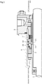
- the mechanical seal for general industrial machine illustrated in FIG. 1 is an inside-type mechanical seal that seals a sealing target liquid F to leak toward the atmospheric side from the sealing target liquid side of sliding surfaces 11 and 21.
- the mechanical seal mainly includes a rotating seal ring 20, which is an annular sliding component provided on a rotary shaft 1 in a state of being rotatable together with the rotary shaft 1 via a sleeve 2, and an annular stationary seal ring 10, which is a sliding component provided on a seal cover 5 fixed to a housing 4 of an attachment target device in a non-rotating state and a state of being movable in the axial direction.
- the sliding surface 11 of the stationary seal ring 10 and the sliding surface 21 of the rotating seal ring 20 slide closely with each other by a bellows 7 urging the stationary seal ring 10 in the axial direction.
- the sliding surface 21 of the rotating seal ring 20 may form a flat surface or may be provided with a recessed portion.
- the stationary seal ring 10 and the rotating seal ring 20 are typically formed of a combination of SiC (as an example of hard material) or a combination of SiC (as the example of hard material) and carbon (as an example of soft material).
- the present invention is not limited thereto and any sliding material can be applied insofar as it is used as a sliding material for a mechanical seal.
- the SiC includes a sintered body using boron, aluminum, carbon, or the like as a sintering aid and a material made of two or more types of phases having different components and compositions, examples of which include SiC in which graphite particles are dispersed, reaction-sintered SiC made of SiC and Si, SiC-TiC, and SiC-TiN.
- the carbon resin-molded carbon, sintered carbon, and the like can be used, including carbon in which carbon and graphite are mixed.
- a metal material, a resin material, a surface modification material (e.g., coating material), a composite material, and the like can also be applied.
- the rotating seal ring 20 slides relative to the stationary seal ring 10 as indicated by the arrow and a plurality of dynamic pressure generation mechanisms 14 are evenly arranged in the circumferential direction of the stationary seal ring 10 on the sliding surface 11 of the stationary seal ring 10.
- the part of the sliding surface 11 other than the dynamic pressure generation mechanism 14 is a land 12 forming a flat surface.
- the part of the sliding surface 11 other than the dynamic pressure generation mechanism 14 is, for example, the part on the atmospheric side as compared with the dynamic pressure generation mechanism 14 and the part between the dynamic pressure generation mechanisms 14 adjacent to each other in the circumferential direction.
- the dynamic pressure generation mechanism 14 will be outlined with reference to FIGS. 2 to 4 .
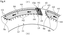
- the left side of the page of FIG. 4 is the downstream side of the sealing target liquid F flowing in a Rayleigh step 9A (described later) and the right side of the page of FIG. 4 is the upstream side of the sealing target liquid F flowing in the Rayleigh step 9A in the following description, when the stationary seal ring 10 and the rotating seal ring 20 are relatively rotated.
- the dynamic pressure generation mechanism 14 includes an introduction groove portion 15 provided with an opening portion 15a communicating with the sealing target liquid F side and extending to the atmospheric side and the Rayleigh step 9A as a dynamic pressure generation groove portion circumferentially extending concentrically with the stationary seal ring 10 toward the downstream side from the atmosphere-side end portion of the introduction groove portion 15.
- the atmosphere-side end portion of the introduction groove portion 15 is blocked and the atmosphere-side end surface thereof is continuous with the atmosphere-side end surface of the Rayleigh step 9A.
- the dynamic pressure generation mechanism 14 has a substantially L shape when the sliding surface 11 is viewed from the orthogonal direction.
- the introduction groove portion 15 of the first embodiment extends in the outer diameter direction so as to be inclined toward the Rayleigh step 9A with reference to the radial direction of the stationary seal ring 10.
- a boundary wall 18 constituting the introduction groove portion 15 and positioned on the boundary side in relation to the Rayleigh step 9A includes an inclined surface 18a extending flat over the entire surface thereof and inclined to the Rayleigh step 9A side with reference to the radial direction from the Rayleigh step 9A side toward the opening portion 15a side, that is, an inclined surface 18a having an outer diameter side positioned downstream of the inner diameter side from the inner diameter side toward the outer diameter side.
- the inclined surface 18a includes a depth-direction step 18b formed at the communication part between the introduction groove portion 15 and the Rayleigh step 9A.
- the introduction groove portion 15 is provided with a facing wall 13 facing the boundary wall 18 in parallel on the upstream side.
- the inclined surface 18a is not limited to the flat shape and the inclined surface 18a may have the shape of a curved surface curved in a concave or convex shape.
- a wall portion 9a inclined with respect to the rotation direction is formed in the downstream-side end portion so as to correspond to the introduction groove portion 15 inclined as described above. It should be noted that the wall portion 9a is not limited to being inclined in the rotation direction. For example, the wall portion 9a may be orthogonal to the rotation direction or may be formed in a staircase shape.
- a depth dimension L10 of the introduction groove portion 15 is deeper than a depth dimension L20 of the Rayleigh step 9A (L10 > L20).
- the depth dimension L10 of the introduction groove portion 15 in the first embodiment is formed to be 100 ⁇ m and the depth dimension L20 of the Rayleigh step 9A is formed to be 5 ⁇ m.
- the depth-direction step 18b is formed between the introduction groove portion 15 and the Rayleigh step 9A by the side surface of the introduction groove portion 15 on the downstream side and the bottom surface of the Rayleigh step 9A.
- the depth dimensions of the introduction groove portion 15 and the Rayleigh step 9A can be freely changed insofar as the depth dimension of the introduction groove portion 15 is formed deeper than the depth dimension of the Rayleigh step 9A and it is preferable that the dimension L10 is at least five times the dimension L20.
- the bottom surface of the Rayleigh step 9A forms a flat surface and is formed parallel to the land 12 and yet does not hinder the flat surface being provided with a fine recess or being formed so as to be inclined with respect to the land 12.
- each of the two circular-arc-shaped surfaces of the Rayleigh step 9A extending in the circumferential direction is orthogonal to the bottom surface of the Rayleigh step 9A.
- the bottom surface of the introduction groove portion 15 forms a flat surface with a uniform depth and is formed parallel to the land 12, the bottom surface of the introduction groove portion 15 does not hinder the flat surface being provided with a fine recess or being formed so as to be inclined with respect to the land 12.
- the bottom surface of the introduction groove portion 15 may be configured to be tapered or stepped so as to become shallow from the opening portion 15a on the sealing target liquid side toward the Rayleigh step 9A on the atmospheric side. Further, each of the two flat surfaces extending to the opening portion 15a of the introduction groove portion 15 is orthogonal to the bottom surface of the introduction groove portion 15.
- the operation of the stationary seal ring 10 and the rotating seal ring 20 during the relative rotation will be described.
- capillarity causes the sealing target liquid F on the sealing target liquid side as compared with the sliding surfaces 11 and 21 to slightly enter between the sliding surfaces 11 and 21 and the dynamic pressure generation mechanism 14 is filled with the sealing target liquid F that has flowed in from the sealing target liquid side in the opening portion 15a of the introduction groove portion 15.
- the sealing target liquid F is higher in viscosity than a gas and thus the amount of leakage from the dynamic pressure generation mechanism 14 to the atmospheric side is small when the general industrial machine is stopped.
- the sealing target liquid F on the sealing target liquid side is introduced from the introduction groove portion 15 as indicated by an arrow H1 in FIG. 4 and the Rayleigh step 9A causes the sealing target liquid F to follow and move in the rotation direction of the rotating seal ring 20 as indicated by an arrow H2.
- the pressure is highest in the vicinity of the wall portion 9a, which is the downstream-side end portion of the Rayleigh step 9A, the sliding surfaces 11 and 21 are separated from each other, a liquid film of the sealing target liquid F is formed on the sliding surface 11, and the sealing target liquid F flows out from the vicinity of the wall portion 9a to the periphery as indicated by an arrow H3.
- the liquid film of the sealing target liquid F is formed in the vicinity of the wall portions 9a, 9a, ... of a plurality of the Rayleigh steps 9A, 9A, ... and thus so-called fluid lubrication occurs between the sliding surfaces 11 and 21, lubricity is improved, and friction reduction is realized.
- the sealing target liquid F in the vicinity of the Rayleigh step 9A does not substantially infiltrate into the Rayleigh step 9A, which is indicated by an arrow H4.
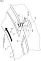
- the contamination C goes over the land 12 from the wall portion 9a and is discharged to the outside along the boundary wall 18 formed in the introduction groove portion 15 arranged side by side downstream of the Rayleigh step 9A even in a case where a very small amount of the contamination C is mixed into the Rayleigh step 9A.
- the boundary wall 18 positioned on the boundary side of the introduction groove portion 15 in relation to the Rayleigh step 9A has the inclined surface 18a where at least the opening portion 15a side of the boundary wall 18 is inclined to the Rayleigh step 9A side with reference to the radial direction and extends to the sealing target liquid side. Accordingly, during the relative rotation of the stationary seal ring 10 and the rotating seal ring 20, the contamination C mixed in the introduction groove portion 15 along with the sealing target liquid F is easily discharged to the sealing target liquid side along the inclined surface 18a of the boundary wall 18, and thus it is possible to prevent the contamination C from entering the Rayleigh step 9A via the introduction groove portion 15 and the lubrication performance and seal function of the sliding surfaces 11 and 21 can be kept satisfactory.
- the inclined surface 18a is formed of a flat surface from the Rayleigh step 9A side toward the sealing target liquid side, and thus the contamination C mixed in the introduction groove portion 15 is more easily discharged to the outside along the flat inclined surface 18a.
- the mechanical seal is an inside-type mechanical seal in which the high-pressure sealing target liquid F is on the sealing target liquid side of the sliding surface and the introduction groove portion 15 communicates with the sealing target liquid and outer diameter sides.
- centrifugal force acts in the outer diameter direction, and thus the mixed contamination C is easily removed.
- a modification example will be described.
- a plurality of the introduction groove portions 15, 15, ... of a first modification example which are arranged side by side along the circumferential direction, mutually communicate via an endlessly extending annular groove 19.
- the fluidity of the contamination C mixed in the introduction groove portion 15 can be further enhanced and the contamination C can be discharged from any of the introduction groove portions 15 arranged side by side in the circumferential direction.
- the depth dimension of the annular groove 19 is substantially equal to the depth dimension of the introduction groove portion 15.
- the annular groove 19 is not limited to being endless and at least two introduction groove portions 15, 15 arranged side by side may be arranged so as to communicate with each other.
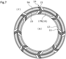
- the sliding surface 11 of a second modification example which is on the atmospheric side as compared with the annular groove 19, is provided with a dynamic pressure generation mechanism 16 having a reverse Rayleigh step 17B.
- a dynamic pressure generation mechanism 16 having a reverse Rayleigh step 17B.
- the reverse Rayleigh step 17B suctions the sealing target liquid F flowing out to the atmospheric side and the leakage of the sealing target liquid F to the atmosphere can be reduced as a result.
- the present invention is not limited to the structure illustrated in FIG. 7 and a negative pressure generation mechanism may be configured that is capable of generating negative pressure on the atmospheric side as compared with the annular groove 19 when the stationary seal ring 10 is relatively rotated.
- an introduction groove portion extends that has a discharge function of communicating with the introduction groove portion 15 and communicating with the sealing target liquid side, and thus the fluidity of the contamination C mixed in the introduction groove portion 15 along with the sealing target liquid F is enhanced and the contamination C can be discharged from the discharge groove portion as well.
- the introduction groove portion having the discharge function of communicating with the introduction groove portion 15 is the introduction groove portion 15 arranged side by side downstream of the introduction groove portion 15, and thus it is possible to achieve a compact structure by using the introduction groove portion having the discharge function as the introduction groove portion 15 on the downstream side thereof as well.
- the plurality of introduction groove portions 15 arranged side by side along the circumferential direction mutually communicate via the endlessly extending annular groove 19, and thus the fluidity of the contamination C mixed in the introduction groove portion 15 is further enhanced and any of the plurality of introduction groove portions 15 arranged side by side in the circumferential direction is easily discharged as the discharge groove portion.
- a dynamic pressure generation mechanism 141 provided in a stationary seal ring 101 includes an introduction groove portion 151 and a Rayleigh step 91A.
- the atmosphere-side end portion of the introduction groove portion 151 is blocked and the atmosphere-side end surface thereof is positioned on the atmospheric side as compared with the atmosphere-side end surface of the Rayleigh step 91A.
- a boundary wall 181 constituting the introduction groove portion 151 and positioned on the boundary side in relation to the Rayleigh step 91A includes an inclined surface 181a extending in the outer diameter direction so as to be inclined toward the Rayleigh step 91A with reference to the radial direction of the stationary seal ring 101 from the sealing target liquid-side end portion of the Rayleigh step 91A and a step 181b as a radial surface extending in the radial direction on the Rayleigh step 91A side as compared with the inclined surface 181a.
- a facing wall 131 is provided with an inclined surface 131a parallel to the inclined surface 181a of the boundary wall 181 and a radial surface 131b parallel to the step 181b.
- a wall portion 91a orthogonal to the rotation direction is formed in the downstream-side end portion in association with the step 181b and the radial surface 131b of the introduction groove portion 151.
- the wall portion 91a is not limited to being orthogonal to the rotation direction.
- the wall portion 91a may be inclined with respect to the rotation direction or may be formed in a staircase shape.
- a plurality of the introduction groove portions 151, 151, ... arranged side by side along the circumferential direction mutually communicate via an endlessly extending annular groove. Accordingly, the fluidity of the contamination C mixed in the introduction groove portion 151 may be further enhanced and any of the plurality of introduction groove portions 151 arranged side by side in the circumferential direction may be easily discharged as a discharge groove portion.
- the boundary wall 181 has the step 181b as a radial surface extending in the radial direction on the Rayleigh step 91A side as compared with the inclined surface 181a.
- the sealing target liquid F proceeds to the Rayleigh step 91A through the step 181b extending in the radial direction, and thus the function of the Rayleigh step 91A groove portion is not impaired.
- the flow that is indicated by an arrow H9 and to move to the sealing target liquid side along the inclined surface 181a inclined to the Rayleigh step 91A side with reference to the radial direction is generated while the step 181b blocks infiltration into the Rayleigh step 91A as indicated by the arrow H9.
- the contamination C mixed in the vicinity of the opening portion 15a of the introduction groove portion 151 is discharged to the sealing target liquid side of the introduction groove portion 151.
- a dynamic pressure generation mechanism 142 provided in a stationary seal ring 102 includes an introduction groove portion 152 and the Rayleigh step 9A and the introduction groove portion 152 has an atmosphere-side end portion communicating with the annular groove 19.
- the boundary wall 18 and a facing wall 132 constitute the introduction groove portion 152, the boundary wall 18 has the inclined surface 18a provided with the step 18b, and the facing wall 132 is inclined to the Rayleigh step 9A side as compared with the boundary wall 18 and extends to the sealing target liquid side.
- the wall portion 9a inclined with respect to the rotation direction is formed in the downstream-side end portion in association with the introduction groove portion 152 inclined as described above. It should be noted that the wall portion 9a is not limited to being inclined in the rotation direction.
- the wall portion 9a may be orthogonal to the rotation direction or may be formed in a staircase shape.
- the introduction groove portion 152 is formed such that an opening portion 152a side communicating with the sealing target liquid side is narrower than the Rayleigh step 9A side, and thus the opening portion 15a is narrow, the sealing target liquid F easily flows in with static pressure, and the contamination C that flows due to dynamic pressure attributable to rotation is unlikely to flow in.
- the flow that is indicated by an arrow H11 and to move to the sealing target liquid side along the boundary wall 18 inclined to the Rayleigh step 9A side with reference to the radial direction is generated while the step 18b blocks infiltration into the Rayleigh step 9A as indicated by the arrow H11.
- the contamination C mixed in the vicinity of the opening portion 152a of the introduction groove portion 152 is discharged to the sealing target liquid side of the introduction groove portion 152.
- the mechanical seal for general industrial machine has been described as an example of the sliding component in the above embodiments, the mechanical seal may be replaced with another mechanical seal for an automobile, a water pump, or the like.
- the present invention is not limited to the mechanical seal and may be a sliding component other than a mechanical seal, examples of which include a slide bearing.
- the dynamic pressure generation mechanism may be provided only on the rotating seal ring 20 or on both the stationary and rotating seal rings.
Landscapes
- Engineering & Computer Science (AREA)
- General Engineering & Computer Science (AREA)
- Mechanical Engineering (AREA)
- Chemical & Material Sciences (AREA)
- Oil, Petroleum & Natural Gas (AREA)
- Physics & Mathematics (AREA)
- Fluid Mechanics (AREA)
- Mechanical Sealing (AREA)
- Sliding-Contact Bearings (AREA)
Abstract
Description
- The present invention relates to sliding components that rotate relative to each other and are used for, for example, a shaft sealing device shaft-sealing a rotary shaft of a rotating machine in the automotive seal field, the general industrial machinery seal field, or another seal field or a bearing of a machine in the automotive bearing field, the general industrial machinery bearing field, or another bearing field.
- A mechanical seal as an example of a shaft sealing device preventing sealing target liquid leakage includes a pair of annular sliding components rotating relative to each other and having sliding surfaces sliding with each other. In recent years and in such mechanical seals, it has been desired for environmental measures or the like to reduce the energy that is lost due to sliding. In this regard, the sliding surface of the sliding component may be provided with a positive pressure generation groove communicating with the high-pressure sealing target liquid side and blocked at one end on the sliding surface.
- For example, in the mechanical seal that is illustrated in Patent
Citation 1, a plurality of dynamic pressure generation mechanisms are circumferentially arranged side by side on the sliding surface of one sliding component and the dynamic pressure generation mechanism includes a radially extending introduction groove portion communicating with a sealing target liquid side and a dynamic pressure generation groove portion communicating with the introduction groove portion and extending in the direction of relative rotation. According to this, during the relative rotation of the sliding component, the sealing target liquid is introduced into the dynamic pressure generation groove portion through the introduction groove portion and the sealing target liquid concentrates on the wall portion of the relative rotation-direction end portion of the dynamic pressure generation groove portion. This leads to positive pressure generation and inter-sliding surface separation and a liquid film of the sealing target liquid is formed on the sliding surface. As a result, lubricity is improved and friction reduction is realized. - Patent Citation 1:
JP H5-60247 A FIG. 2 ) - In this manner, in
Patent Citation 1, the friction between the sliding components can be reduced by the sealing target fluid being supplied between the sliding components from the end point of the dynamic pressure generation groove. Meanwhile, when the sealing target fluid contains contamination, the contamination may stay in the introduction groove portion, may further enter the dynamic pressure generation groove portion through the introduction groove portion, and may cause stagnation, sedimentation, or wear in the vicinity of the blocked end point of the dynamic pressure generation groove portion in particular. Accordingly, this inter-sliding surface contamination may damage the sliding surface and adversely affect the performance of a rotating machine. It should be noted that "contamination" in the present application means "particulate foreign matter" such as polyfine particle-shaped conductive foreign matter. - The present invention has been made in view of such problems, and an object of the present invention is to provide a sliding component capable of keeping the lubrication performance and seal function of a sliding surface satisfactory by suppressing the stay of contamination mixed in an introduction groove portion and preventing the contamination from entering a dynamic pressure generation groove portion.
- In order to solve the above problem, the sliding component according to the present invention is a sliding component formed in an annular shape and disposed at a relative rotation point of a rotating machine, including a plurality of dynamic pressure generation mechanisms circumferentially arranged on a sliding surface of the sliding component, each of the dynamic pressure generation mechanisms including an introduction groove portion communicating with a sealing target fluid side through an opening portion of the introduction groove portion and a dynamic pressure generation groove portion communicating with the introduction groove portion and extending in a circumferential direction in which the sliding component is relatively rotated with respect to a mating sliding component, wherein the introduction groove portion is partially defined by a boundary wall positioned between the introduction groove portion and the dynamic pressure generation groove portion, and the boundary wall has an inclined surface where at least a portion of the boundary wall positioned on a side of the opening portion extends toward the sealing target fluid side so as to be inclined to a side of the dynamic pressure generation groove portion. According to the aforesaid feature of the present invention, during the relative rotation of the sliding components, contamination mixed in the introduction groove portion along with the sealing target fluid is easily discharged to the sealing target fluid side along the inclined surface of the boundary wall, and thus it is possible to prevent the contamination from entering the dynamic pressure generation groove portion via the introduction groove portion and the lubrication performance and seal function of the sliding surface can be kept satisfactory.
- It may be preferable that the inclined surface is formed of a flat surface from the side of the dynamic pressure generation groove portion toward the sealing target fluid side. According to this preferable configuration, the contamination mixed in the introduction groove portion is easily discharged to the outside along the inclined surface since the inclined surface is flat.
- It may be preferable that the boundary wall has a radial surface radially extending on the side of the dynamic pressure generation groove portion as compared with the inclined surface. According to this preferable configuration, the sealing target fluid proceeds to the dynamic pressure generation groove portion through the radial surface extending in the radial direction, and thus the function of the dynamic pressure generation groove portion is not impaired.
- It may be preferable that, the introduction groove portion is formed such that a circumferential width of the introduction groove portion on the side of the opening portion communicating with the sealing target fluid side is narrower than a circumferential width of the introduction groove portion on the side of the dynamic pressure generation groove. According to this preferable configuration, the contamination that flows with rotation is unlikely to flow in since the opening portion is narrow.
- It may be preferable that the introduction groove portions arranged in the circumferential direction mutually communicate via an endlessly extending annular groove formed in the sliding surface. According to this preferable configuration, the fluidity of the contamination mixed in the introduction groove portion is further enhanced and any of the plurality of introduction groove portions arranged side by side in the circumferential direction is easily discharged as a discharge groove portion.
- It may be preferable that the introduction groove portion communicates with an outer diameter side of the sliding component which is the sealing target fluid side. According to this preferable configuration, centrifugal force acts in the outer diameter direction, and thus the mixed contamination is easily removed.
- It may be preferable that a discharge groove portion communicating with the introduction groove portion and communicating with the sealing target fluid side is provided. According to this preferable configuration, the fluidity of the contamination mixed in the introduction groove portion along with the sealing target fluid can be enhanced and the contamination can be discharged to the sealing target fluid side from the discharge groove portion as well.
- It may be preferable that the discharge groove portion communicating with the introduction groove portion is an introduction groove portion having the discharge function of the dynamic pressure generation mechanism arranged side by side downstream of the introduction groove portion. According to this preferable configuration, it is possible to achieve a compact structure by using the discharge groove portion communicating with the introduction groove portion as the introduction groove portion on the downstream side thereof as well.
-
-
FIG. 1 is a vertical cross-sectional view illustrating the mechanical seal including a sliding component according to a first embodiment of the present invention. -
FIG. 2 is a diagram in which the sliding surface of a stationary seal ring is viewed from the axial direction in the first embodiment. -
FIG. 3 is a cross-sectional view taken along line A-A ofFIG. 2 . -
FIG. 4 is an enlarged view of a main part of the sliding surface of the stationary seal ring in the first embodiment. -
FIG. 5 is a perspective view illustrating a situation in which contamination mixed in an introduction groove portion is discharged in the first embodiment. -
FIG. 6 is an explanatory diagram illustrating a first modification example of the first embodiment. -
FIG. 7 is an explanatory diagram illustrating a second modification example of the first embodiment. -
FIG. 8 is a diagram in which the sliding surface of the stationary seal ring as a sliding component according to a second embodiment of the present invention is viewed from the axial direction. -
FIG. 9 is a diagram in which the sliding surface of the stationary seal ring as a sliding component according to a third embodiment of the present invention is viewed from the axial direction. - Modes for implementing the sliding component according to the present invention will be described below based on embodiments.
- The sliding component according to the first embodiment of the present invention will be described with reference to
FIGS. 1 to 5 . It should be noted that a mode in which the sliding component is a mechanical seal will be described as an example in the present embodiment. In addition, in the following description, the outer diameter side of the sliding component constituting the mechanical seal is a sealing target liquid side (i.e., high-pressure side) and the inner diameter side is an atmospheric side (i.e., leak side, low-pressure side). It should be noted that the present invention is not limited thereto, the sealing target liquid side may be the low-pressure side and the leak side may be the high-pressure side, and the sealing target fluid is not limited to a liquid and may be a gas, examples of which include the atmosphere. In addition, for convenience of description, dots may be added to, for example, the grooves formed in the sliding surface in the drawings. - The mechanical seal for general industrial machine illustrated in
FIG. 1 is an inside-type mechanical seal that seals a sealing target liquid F to leak toward the atmospheric side from the sealing target liquid side of slidingsurfaces seal ring 20, which is an annular sliding component provided on arotary shaft 1 in a state of being rotatable together with therotary shaft 1 via asleeve 2, and an annularstationary seal ring 10, which is a sliding component provided on aseal cover 5 fixed to ahousing 4 of an attachment target device in a non-rotating state and a state of being movable in the axial direction. The slidingsurface 11 of thestationary seal ring 10 and the slidingsurface 21 of the rotatingseal ring 20 slide closely with each other by abellows 7 urging thestationary seal ring 10 in the axial direction. It should be noted that the slidingsurface 21 of the rotatingseal ring 20 may form a flat surface or may be provided with a recessed portion. - The
stationary seal ring 10 and the rotatingseal ring 20 are typically formed of a combination of SiC (as an example of hard material) or a combination of SiC (as the example of hard material) and carbon (as an example of soft material). However, the present invention is not limited thereto and any sliding material can be applied insofar as it is used as a sliding material for a mechanical seal. It should be noted that the SiC includes a sintered body using boron, aluminum, carbon, or the like as a sintering aid and a material made of two or more types of phases having different components and compositions, examples of which include SiC in which graphite particles are dispersed, reaction-sintered SiC made of SiC and Si, SiC-TiC, and SiC-TiN. As the carbon, resin-molded carbon, sintered carbon, and the like can be used, including carbon in which carbon and graphite are mixed. In addition to the above sliding materials, a metal material, a resin material, a surface modification material (e.g., coating material), a composite material, and the like can also be applied. - As illustrated in
FIG. 2 , the rotatingseal ring 20 slides relative to thestationary seal ring 10 as indicated by the arrow and a plurality of dynamicpressure generation mechanisms 14 are evenly arranged in the circumferential direction of thestationary seal ring 10 on the slidingsurface 11 of thestationary seal ring 10. The part of the slidingsurface 11 other than the dynamicpressure generation mechanism 14 is aland 12 forming a flat surface. To be more specific, the part of the slidingsurface 11 other than the dynamicpressure generation mechanism 14 is, for example, the part on the atmospheric side as compared with the dynamicpressure generation mechanism 14 and the part between the dynamicpressure generation mechanisms 14 adjacent to each other in the circumferential direction. - Next, the dynamic
pressure generation mechanism 14 will be outlined with reference toFIGS. 2 to 4 . It should be noted that the left side of the page ofFIG. 4 is the downstream side of the sealing target liquid F flowing in aRayleigh step 9A (described later) and the right side of the page ofFIG. 4 is the upstream side of the sealing target liquid F flowing in theRayleigh step 9A in the following description, when thestationary seal ring 10 and therotating seal ring 20 are relatively rotated. - The dynamic
pressure generation mechanism 14 includes anintroduction groove portion 15 provided with anopening portion 15a communicating with the sealing target liquid F side and extending to the atmospheric side and theRayleigh step 9A as a dynamic pressure generation groove portion circumferentially extending concentrically with thestationary seal ring 10 toward the downstream side from the atmosphere-side end portion of theintroduction groove portion 15. In addition, the atmosphere-side end portion of theintroduction groove portion 15 is blocked and the atmosphere-side end surface thereof is continuous with the atmosphere-side end surface of theRayleigh step 9A. In other words, by theintroduction groove portion 15 and theRayleigh step 9A, the dynamicpressure generation mechanism 14 has a substantially L shape when the slidingsurface 11 is viewed from the orthogonal direction. - In addition, the
introduction groove portion 15 of the first embodiment extends in the outer diameter direction so as to be inclined toward theRayleigh step 9A with reference to the radial direction of thestationary seal ring 10. In addition, aboundary wall 18 constituting theintroduction groove portion 15 and positioned on the boundary side in relation to theRayleigh step 9A includes aninclined surface 18a extending flat over the entire surface thereof and inclined to theRayleigh step 9A side with reference to the radial direction from theRayleigh step 9A side toward theopening portion 15a side, that is, aninclined surface 18a having an outer diameter side positioned downstream of the inner diameter side from the inner diameter side toward the outer diameter side. Theinclined surface 18a includes a depth-direction step 18b formed at the communication part between theintroduction groove portion 15 and theRayleigh step 9A. Further, theintroduction groove portion 15 is provided with a facingwall 13 facing theboundary wall 18 in parallel on the upstream side. It should be noted that theinclined surface 18a is not limited to the flat shape and theinclined surface 18a may have the shape of a curved surface curved in a concave or convex shape. - In addition, in the
Rayleigh step 9A, awall portion 9a inclined with respect to the rotation direction is formed in the downstream-side end portion so as to correspond to theintroduction groove portion 15 inclined as described above. It should be noted that thewall portion 9a is not limited to being inclined in the rotation direction. For example, thewall portion 9a may be orthogonal to the rotation direction or may be formed in a staircase shape. - In addition, a depth dimension L10 of the
introduction groove portion 15 is deeper than a depth dimension L20 of theRayleigh step 9A (L10 > L20). Specifically, the depth dimension L10 of theintroduction groove portion 15 in the first embodiment is formed to be 100 µm and the depth dimension L20 of theRayleigh step 9A is formed to be 5 µm. In other words, the depth-direction step 18b is formed between theintroduction groove portion 15 and theRayleigh step 9A by the side surface of theintroduction groove portion 15 on the downstream side and the bottom surface of theRayleigh step 9A. It should be noted that the depth dimensions of theintroduction groove portion 15 and theRayleigh step 9A can be freely changed insofar as the depth dimension of theintroduction groove portion 15 is formed deeper than the depth dimension of theRayleigh step 9A and it is preferable that the dimension L10 is at least five times the dimension L20. - It should be noted that the bottom surface of the
Rayleigh step 9A forms a flat surface and is formed parallel to theland 12 and yet does not hinder the flat surface being provided with a fine recess or being formed so as to be inclined with respect to theland 12. Further, each of the two circular-arc-shaped surfaces of theRayleigh step 9A extending in the circumferential direction is orthogonal to the bottom surface of theRayleigh step 9A. In addition, although the bottom surface of theintroduction groove portion 15 forms a flat surface with a uniform depth and is formed parallel to theland 12, the bottom surface of theintroduction groove portion 15 does not hinder the flat surface being provided with a fine recess or being formed so as to be inclined with respect to theland 12. For example, the bottom surface of theintroduction groove portion 15 may be configured to be tapered or stepped so as to become shallow from theopening portion 15a on the sealing target liquid side toward theRayleigh step 9A on the atmospheric side. Further, each of the two flat surfaces extending to theopening portion 15a of theintroduction groove portion 15 is orthogonal to the bottom surface of theintroduction groove portion 15. - Next, the operation of the
stationary seal ring 10 and therotating seal ring 20 during the relative rotation will be described. First, during the non-operation of a general industrial machine and non-rotation of therotating seal ring 20, capillarity causes the sealing target liquid F on the sealing target liquid side as compared with the slidingsurfaces surfaces pressure generation mechanism 14 is filled with the sealing target liquid F that has flowed in from the sealing target liquid side in theopening portion 15a of theintroduction groove portion 15. It should be noted that the sealing target liquid F is higher in viscosity than a gas and thus the amount of leakage from the dynamicpressure generation mechanism 14 to the atmospheric side is small when the general industrial machine is stopped. - When the
rotating seal ring 20 rotates relative to the stationary seal ring 10 (see the black arrow inFIG. 2 ) from the stopped state of the general industrial machine, the sealing target liquid F on the sealing target liquid side is introduced from theintroduction groove portion 15 as indicated by an arrow H1 inFIG. 4 and theRayleigh step 9A causes the sealing target liquid F to follow and move in the rotation direction of therotating seal ring 20 as indicated by an arrow H2. This leads to dynamic pressure generation in theRayleigh step 9A. It should be noted that the pressure gradually decreases toward the upstream side of theRayleigh step 9A. - The pressure is highest in the vicinity of the
wall portion 9a, which is the downstream-side end portion of theRayleigh step 9A, the slidingsurfaces surface 11, and the sealing target liquid F flows out from the vicinity of thewall portion 9a to the periphery as indicated by an arrow H3. According to this, the liquid film of the sealing target liquid F is formed in the vicinity of thewall portions surfaces Rayleigh step 9A as described above, the sealing target liquid F in the vicinity of theRayleigh step 9A does not substantially infiltrate into theRayleigh step 9A, which is indicated by an arrow H4. - Next, the operation of discharging contamination C mixed in the
introduction groove portion 15 will be described. As illustrated inFIG. 5 , when therotating seal ring 20 rotates relative to thestationary seal ring 10 with the dynamicpressure generation mechanism 14 filled with the sealing target liquid F, the sealing target liquid F in the dynamicpressure generation mechanism 14 moves to the downstream side in the circumferential direction. At this time, a flow to enter theRayleigh step 9A is generated, as indicated by an arrow H6, as for the sealing target liquid F on the surface side facing therotating seal ring 20. Meanwhile, as for the sealing target liquid F on the bottom surface side of theintroduction groove portion 15 larger in dent amount than the bottom surface of theRayleigh step 9A, a flow to move to the sealing target liquid side along theinclined boundary wall 18 is generated, as indicated by an arrow H7, while thestep 18b blocks infiltration into theRayleigh step 9A. By riding this flow indicated by the arrow H7, the contamination C mixed in the vicinity of theopening portion 15a of theintroduction groove portion 15 is discharged from theintroduction groove portion 15 to the sealing target liquid side outside thestationary seal ring 10. As described above, most of the contamination C is discharged to the outside of theintroduction groove portion 15 without being mixed into theRayleigh step 9A. It should be noted that the contamination C goes over theland 12 from thewall portion 9a and is discharged to the outside along theboundary wall 18 formed in theintroduction groove portion 15 arranged side by side downstream of theRayleigh step 9A even in a case where a very small amount of the contamination C is mixed into theRayleigh step 9A. - As described above, the
boundary wall 18 positioned on the boundary side of theintroduction groove portion 15 in relation to theRayleigh step 9A has theinclined surface 18a where at least theopening portion 15a side of theboundary wall 18 is inclined to theRayleigh step 9A side with reference to the radial direction and extends to the sealing target liquid side. Accordingly, during the relative rotation of thestationary seal ring 10 and therotating seal ring 20, the contamination C mixed in theintroduction groove portion 15 along with the sealing target liquid F is easily discharged to the sealing target liquid side along theinclined surface 18a of theboundary wall 18, and thus it is possible to prevent the contamination C from entering theRayleigh step 9A via theintroduction groove portion 15 and the lubrication performance and seal function of the slidingsurfaces - In addition, the
inclined surface 18a is formed of a flat surface from theRayleigh step 9A side toward the sealing target liquid side, and thus the contamination C mixed in theintroduction groove portion 15 is more easily discharged to the outside along the flatinclined surface 18a. - In addition, in the present embodiment, the mechanical seal is an inside-type mechanical seal in which the high-pressure sealing target liquid F is on the sealing target liquid side of the sliding surface and the
introduction groove portion 15 communicates with the sealing target liquid and outer diameter sides. As a result, centrifugal force acts in the outer diameter direction, and thus the mixed contamination C is easily removed. - Next, a modification example will be described. As illustrated in
FIG. 6 , a plurality of theintroduction groove portions annular groove 19. According to this, the fluidity of the contamination C mixed in theintroduction groove portion 15 can be further enhanced and the contamination C can be discharged from any of theintroduction groove portions 15 arranged side by side in the circumferential direction. It should be noted that the depth dimension of theannular groove 19 is substantially equal to the depth dimension of theintroduction groove portion 15. Further, theannular groove 19 is not limited to being endless and at least twointroduction groove portions - In addition, as illustrated in
FIG. 7 , the slidingsurface 11 of a second modification example, which is on the atmospheric side as compared with theannular groove 19, is provided with a dynamicpressure generation mechanism 16 having areverse Rayleigh step 17B. According to this, when therotating seal ring 20 rotates relative to thestationary seal ring 10 and negative pressure is generated on the upstream side of thereverse Rayleigh step 17B, thereverse Rayleigh step 17B suctions the sealing target liquid F flowing out to the atmospheric side and the leakage of the sealing target liquid F to the atmosphere can be reduced as a result. It should be noted that the present invention is not limited to the structure illustrated inFIG. 7 and a negative pressure generation mechanism may be configured that is capable of generating negative pressure on the atmospheric side as compared with theannular groove 19 when thestationary seal ring 10 is relatively rotated. - As described above, in the first and second modification examples, an introduction groove portion extends that has a discharge function of communicating with the
introduction groove portion 15 and communicating with the sealing target liquid side, and thus the fluidity of the contamination C mixed in theintroduction groove portion 15 along with the sealing target liquid F is enhanced and the contamination C can be discharged from the discharge groove portion as well. - In addition, the introduction groove portion having the discharge function of communicating with the
introduction groove portion 15 is theintroduction groove portion 15 arranged side by side downstream of theintroduction groove portion 15, and thus it is possible to achieve a compact structure by using the introduction groove portion having the discharge function as theintroduction groove portion 15 on the downstream side thereof as well. - In addition, the plurality of
introduction groove portions 15 arranged side by side along the circumferential direction mutually communicate via the endlessly extendingannular groove 19, and thus the fluidity of the contamination C mixed in theintroduction groove portion 15 is further enhanced and any of the plurality ofintroduction groove portions 15 arranged side by side in the circumferential direction is easily discharged as the discharge groove portion. - Next, the sliding component according to the second embodiment of the present invention will be described with reference to
FIG. 8 . It should be noted that configurations identical to those of the first embodiment will not be described below so that redundancy can be avoided. - As illustrated in
FIG. 8 , a dynamicpressure generation mechanism 141 provided in astationary seal ring 101 includes anintroduction groove portion 151 and aRayleigh step 91A. In addition, the atmosphere-side end portion of theintroduction groove portion 151 is blocked and the atmosphere-side end surface thereof is positioned on the atmospheric side as compared with the atmosphere-side end surface of theRayleigh step 91A. Aboundary wall 181 constituting theintroduction groove portion 151 and positioned on the boundary side in relation to theRayleigh step 91A includes aninclined surface 181a extending in the outer diameter direction so as to be inclined toward theRayleigh step 91A with reference to the radial direction of thestationary seal ring 101 from the sealing target liquid-side end portion of theRayleigh step 91A and astep 181b as a radial surface extending in the radial direction on theRayleigh step 91A side as compared with theinclined surface 181a. Likewise, a facingwall 131 is provided with aninclined surface 131a parallel to theinclined surface 181a of theboundary wall 181 and aradial surface 131b parallel to thestep 181b. - In addition, in the
Rayleigh step 91A, awall portion 91a orthogonal to the rotation direction is formed in the downstream-side end portion in association with thestep 181b and theradial surface 131b of theintroduction groove portion 151. It should be noted that thewall portion 91a is not limited to being orthogonal to the rotation direction. For example, thewall portion 91a may be inclined with respect to the rotation direction or may be formed in a staircase shape. - It should be noted that a plurality of the
introduction groove portions introduction groove portion 151 may be further enhanced and any of the plurality ofintroduction groove portions 151 arranged side by side in the circumferential direction may be easily discharged as a discharge groove portion. - As described above, the
boundary wall 181 has thestep 181b as a radial surface extending in the radial direction on theRayleigh step 91A side as compared with theinclined surface 181a. As a result, the sealing target liquid F proceeds to theRayleigh step 91A through thestep 181b extending in the radial direction, and thus the function of theRayleigh step 91A groove portion is not impaired. - Next, the operation of discharging the contamination C mixed in the
introduction groove portion 151 will be described. As illustrated in the enlarged view ofFIG. 8 , when therotating seal ring 20 rotates relative to thestationary seal ring 101 with the dynamicpressure generation mechanism 141 filled with the sealing target liquid F, the sealing target liquid F in the dynamicpressure generation mechanism 141 moves to the downstream side in the circumferential direction. At this time, a flow to infiltrate into theRayleigh step 91A is generated, as indicated by an arrow H8, as for the sealing target liquid F on the surface side facing therotating seal ring 20. Meanwhile, as for the sealing target liquid F on the bottom surface side as compared with the bottom surface of theRayleigh step 91A, the flow that is indicated by an arrow H9 and to move to the sealing target liquid side along theinclined surface 181a inclined to theRayleigh step 91A side with reference to the radial direction is generated while thestep 181b blocks infiltration into theRayleigh step 91A as indicated by the arrow H9. By riding this flow indicated by the arrow H9, the contamination C mixed in the vicinity of theopening portion 15a of theintroduction groove portion 151 is discharged to the sealing target liquid side of theintroduction groove portion 151. As described above, most of the contamination C is discharged to the outside of theintroduction groove portion 151 without being mixed into theRayleigh step 91A, and yet the contamination C goes over theland 12 from thewall portion 91a and is discharged along theinclined surface 181a formed in theintroduction groove portions 151 arranged side by side downstream of theRayleigh step 91A even in a case where a very small amount of the contamination C is mixed into theRayleigh step 91A. - Next, the sliding component according to the third embodiment of the present invention will be described with reference to
FIG. 9 . It should be noted that configurations identical to those of the second embodiment will not be described below so that redundancy can be avoided. - As illustrated in
FIG. 9 , a dynamicpressure generation mechanism 142 provided in astationary seal ring 102 includes anintroduction groove portion 152 and theRayleigh step 9A and theintroduction groove portion 152 has an atmosphere-side end portion communicating with theannular groove 19. Theboundary wall 18 and a facingwall 132 constitute theintroduction groove portion 152, theboundary wall 18 has theinclined surface 18a provided with thestep 18b, and the facingwall 132 is inclined to theRayleigh step 9A side as compared with theboundary wall 18 and extends to the sealing target liquid side. - In addition, in the
Rayleigh step 9A, thewall portion 9a inclined with respect to the rotation direction is formed in the downstream-side end portion in association with theintroduction groove portion 152 inclined as described above. It should be noted that thewall portion 9a is not limited to being inclined in the rotation direction. For example, thewall portion 9a may be orthogonal to the rotation direction or may be formed in a staircase shape. - It should be noted that a plurality of the
introduction groove portions annular groove 19. Accordingly, the fluidity of the contamination C mixed in theintroduction groove portion 151 is further enhanced and any of the plurality ofintroduction groove portions 151 arranged side by side in the circumferential direction is easily discharged as a discharge groove portion, and yet the present invention is not limited thereto and theannular groove 19 may not be provided. - As described above, the
introduction groove portion 152 is formed such that anopening portion 152a side communicating with the sealing target liquid side is narrower than theRayleigh step 9A side, and thus theopening portion 15a is narrow, the sealing target liquid F easily flows in with static pressure, and the contamination C that flows due to dynamic pressure attributable to rotation is unlikely to flow in. - Next, the operation of discharging the contamination C mixed in the
introduction groove portion 152 will be described. As illustrated in the enlarged view ofFIG. 9 , when therotating seal ring 20 rotates relative to thestationary seal ring 102 with the dynamicpressure generation mechanism 142 filled with the sealing target liquid F, the sealing target liquid F in the dynamicpressure generation mechanism 142 moves to the downstream side in the circumferential direction. At this time, a flow to infiltrate into theRayleigh step 9A is generated, as indicated by an arrow H10, as for the sealing target liquid F on the surface side facing therotating seal ring 20. Meanwhile, as for the sealing target liquid F on the bottom surface side as compared with the bottom surface of theRayleigh step 9A, the flow that is indicated by an arrow H11 and to move to the sealing target liquid side along theboundary wall 18 inclined to theRayleigh step 9A side with reference to the radial direction is generated while thestep 18b blocks infiltration into theRayleigh step 9A as indicated by the arrow H11. By riding this flow indicated by the arrow H11, the contamination C mixed in the vicinity of theopening portion 152a of theintroduction groove portion 152 is discharged to the sealing target liquid side of theintroduction groove portion 152. As described above, most of the contamination C is discharged to the outside of theintroduction groove portion 152 without being mixed into theRayleigh step 9A, and yet the contamination C goes over theland 12 from thewall portion 9a and is discharged along theboundary wall 18 formed in theintroduction groove portions 152 arranged side by side downstream of theRayleigh step 9A even in a case where a very small amount of the contamination C is mixed into theRayleigh step 9A. - Although embodiments of the present invention have been described above with reference to the drawings, the specific configuration is not limited to the embodiments and any change or addition within the scope of the gist of the present invention is included in the present invention.
- For example, although the mechanical seal for general industrial machine has been described as an example of the sliding component in the above embodiments, the mechanical seal may be replaced with another mechanical seal for an automobile, a water pump, or the like. In addition, the present invention is not limited to the mechanical seal and may be a sliding component other than a mechanical seal, examples of which include a slide bearing.
- In addition, although an example in which the dynamic pressure generation mechanism is provided only on the stationary seal ring has been described in the above embodiment, the dynamic pressure generation mechanism may be provided only on the
rotating seal ring 20 or on both the stationary and rotating seal rings. - In addition, although a mode in which the sliding component is provided with a plurality of dynamic pressure generation mechanisms having the same shape has been exemplified in the above embodiment, a plurality of dynamic pressure generation mechanisms having different shapes may be provided. In addition, the interval, quantity, and so on of the dynamic pressure generation mechanisms can be changed as appropriate.
-
- 1
- Rotary shaft
- 2
- Sleeve
- 4
- Housing
- 5
- Seal cover
- 7
- Bellows
- 9A
- Rayleigh step (dynamic pressure generation groove portion)
- 10
- Stationary seal ring (sliding component)
- 11
- Sliding surface
- 12
- Land
- 14
- Dynamic pressure generation mechanism
- 15
- Introduction groove portion
- 15a
- Opening portion
- 18
- Boundary wall
- 18a
- Inclined surface
- 19
- Annular groove
- 20
- Rotating seal ring
- 21
- Sliding surface
- 91A
- Rayleigh step (dynamic pressure generation groove portion)
- 181
- Boundary wall
- 181a
- Inclined surface
- 181b
- Step (radial surface)
Claims (6)
- A sliding component formed in an annular shape and disposed at a relative rotation point of a rotating machine, comprising a plurality of dynamic pressure generation mechanisms circumferentially arranged on a sliding surface of the sliding component, each of the dynamic pressure generation mechanisms including an introduction groove portion communicating with a sealing target fluid side through an opening portion of the introduction groove portion and a dynamic pressure generation groove portion communicating with the introduction groove portion and extending in a circumferential direction in which the sliding component is relatively rotated with respect to a mating sliding component, wherein
the introduction groove portion is partially defined by a boundary wall positioned between the introduction groove portion and the dynamic pressure generation groove portion, and the boundary wall has an inclined surface where at least a portion of the boundary wall positioned on a side of the opening portion extends toward the sealing target fluid side so as to be inclined to a side of the dynamic pressure generation groove portion. - The sliding component according to claim 1, wherein the inclined surface is formed of a flat surface from the side of the dynamic pressure generation groove portion toward the sealing target fluid side.
- The sliding component according to claim 1, wherein the boundary wall has a radial surface radially extending on the side of the dynamic pressure generation groove portion as compared with the inclined surface.
- The sliding component according to any one of claims 1 to 3, wherein the introduction groove portion is formed such that a circumferential width of the introduction groove portion on the side of the opening portion communicating with the sealing target fluid side is narrower than a circumferential width of the introduction groove portion on the side of the dynamic pressure generation groove.
- The sliding component according to any one of claims 1 to 4, wherein the introduction groove portions arranged in the circumferential direction mutually communicate via an endlessly extending annular groove formed in the sliding surface.
- The sliding component according to any one of claims 1 to 5, wherein the introduction groove portion communicates with an outer diameter side of the sliding component which is the sealing target fluid side.
Applications Claiming Priority (2)
| Application Number | Priority Date | Filing Date | Title |
|---|---|---|---|
| JP2019054193 | 2019-03-22 | ||
| PCT/JP2020/011926 WO2020196145A1 (en) | 2019-03-22 | 2020-03-18 | Sliding component |
Publications (2)
| Publication Number | Publication Date |
|---|---|
| EP3943765A1 true EP3943765A1 (en) | 2022-01-26 |
| EP3943765A4 EP3943765A4 (en) | 2022-11-30 |
Family
ID=72610175
Family Applications (1)
| Application Number | Title | Priority Date | Filing Date |
|---|---|---|---|
| EP20777157.7A Pending EP3943765A4 (en) | 2019-03-22 | 2020-03-18 | Sliding component |
Country Status (6)
| Country | Link |
|---|---|
| US (1) | US12467538B2 (en) |
| EP (1) | EP3943765A4 (en) |
| JP (1) | JP7419346B2 (en) |
| KR (1) | KR102651943B1 (en) |
| CN (1) | CN113508238B (en) |
| WO (1) | WO2020196145A1 (en) |
Cited By (15)
| Publication number | Priority date | Publication date | Assignee | Title |
|---|---|---|---|---|
| EP3832178A4 (en) * | 2018-08-01 | 2022-04-27 | Eagle Industry Co., Ltd. | SLIDING ELEMENT |
| US11815184B2 (en) | 2018-11-30 | 2023-11-14 | Eagle Industry Co., Ltd. | Sliding component |
| US11821521B2 (en) | 2018-12-21 | 2023-11-21 | Eagle Industry Co., Ltd. | Sliding component |
| US11821462B2 (en) | 2018-08-24 | 2023-11-21 | Eagle Industry Co., Ltd. | Sliding member |
| US11892081B2 (en) | 2019-07-26 | 2024-02-06 | Eagle Industry Co., Ltd. | Sliding component |
| US11933405B2 (en) | 2019-02-14 | 2024-03-19 | Eagle Industry Co., Ltd. | Sliding component |
| US12013040B2 (en) | 2019-02-21 | 2024-06-18 | Eagle Industry Co., Ltd. | Sliding components |
| US12018757B2 (en) | 2019-02-04 | 2024-06-25 | Eagle Industry Co., Ltd. | Sliding components |
| US12152631B2 (en) | 2018-10-24 | 2024-11-26 | Eagle Industry Co., Ltd. | Sliding member |
| US12188516B2 (en) | 2020-06-02 | 2025-01-07 | Eagle Industry Co., Ltd. | Sliding component |
| US12247666B2 (en) | 2021-03-12 | 2025-03-11 | Eagle Industry Co., Ltd. | Sliding component |
| US12276338B2 (en) | 2020-06-02 | 2025-04-15 | Eagle Industry Co., Ltd. | Sliding component |
| US12379031B2 (en) | 2018-10-01 | 2025-08-05 | Eagle Industry Co., Ltd. | Sliding member |
| US12404936B2 (en) | 2021-09-28 | 2025-09-02 | Eagle Indusry Co., Ltd. | Sliding component |
| US12473946B2 (en) | 2021-07-13 | 2025-11-18 | Eagle Industry Co., Ltd. | Sliding components |
Families Citing this family (7)
| Publication number | Priority date | Publication date | Assignee | Title |
|---|---|---|---|---|
| EP3816490B1 (en) * | 2018-05-17 | 2024-11-06 | Eagle Industry Co., Ltd. | Seal ring |
| US11644100B2 (en) | 2018-05-17 | 2023-05-09 | Eagle Industry Co., Ltd. | Seal ring |
| CN115210488B (en) * | 2020-03-09 | 2025-12-23 | 伊格尔工业股份有限公司 | Sliding member |
| CN115280047B (en) | 2020-03-26 | 2025-09-12 | 伊格尔工业股份有限公司 | Sliding parts |
| EP4502432A4 (en) | 2022-03-24 | 2026-02-25 | Eagle Ind Co Ltd | SLIDING COMPONENT |
| CN114857273B (en) * | 2022-03-31 | 2023-06-02 | 清华大学 | End face seal assembly |
| CN119301388A (en) * | 2022-06-07 | 2025-01-10 | 伊格尔工业股份有限公司 | Sliding parts |
Family Cites Families (185)
| Publication number | Priority date | Publication date | Assignee | Title |
|---|---|---|---|---|
| US3383116A (en) | 1964-09-30 | 1968-05-14 | J C Carter Company | Face seal |
| FR1505487A (en) | 1966-10-28 | 1967-12-15 | Guinard Pompes | Improvement in leak-controlled rotary joints |
| US3695789A (en) | 1970-04-13 | 1972-10-03 | Case Co J I | Balancing mechanism for fluid translating device |
| US3704019A (en) | 1970-06-19 | 1972-11-28 | Gen Electric | Spiral groove face seals |
| US3782737A (en) | 1970-07-13 | 1974-01-01 | Nasa | Spiral groove seal |
| US3675935A (en) | 1970-07-13 | 1972-07-11 | Nasa | Spiral groove seal |
| NL7213192A (en) | 1972-09-29 | 1974-04-02 | ||
| US4056478A (en) | 1973-10-04 | 1977-11-01 | Sargent Industries, Inc. | Bearing material employing frangible microcapsules containing lubricant |
| JPS5134974A (en) | 1974-09-19 | 1976-03-25 | Kinugawa Rubber Ind | Dainamitsukushiiru no seiho |
| DE2504204C3 (en) | 1975-02-01 | 1981-11-12 | Skf Kugellagerfabriken Gmbh, 8720 Schweinfurt | Self-pressure generating axial slide bearing |
| FR2342440A1 (en) | 1976-02-27 | 1977-09-23 | Ca Atomic Energy Ltd | Face seal for rotating shaft - has collar with chain of blind holes connected by grooves to increase resistance to flow |
| DE2610045C2 (en) | 1976-03-11 | 1982-06-16 | M.A.N. Maschinenfabrik Augsburg-Nürnberg AG, 4200 Oberhausen | Gas-locked shaft seal |
| JPS576833Y2 (en) * | 1976-04-24 | 1982-02-09 | ||
| DE2622772C3 (en) | 1976-05-21 | 1980-05-08 | Hoesch Werke Ag, 4600 Dortmund | Device for transporting and changing rolls on roll processing machines |
| DE2624849C3 (en) | 1976-06-03 | 1981-12-03 | Skf Kugellagerfabriken Gmbh, 8720 Schweinfurt | Self-pressure generating radial plain bearing |
| JPS57163770A (en) | 1981-04-01 | 1982-10-08 | Eagle Ind Co Ltd | Mechanical seal |
| DE3223703C2 (en) | 1982-06-25 | 1984-05-30 | M.A.N. Maschinenfabrik Augsburg-Nürnberg AG, 4200 Oberhausen | Gas-locked shaft seal with radial sealing gap |
| JPS59195253A (en) | 1983-04-20 | 1984-11-06 | Canon Inc | Electrophotographic apparatus |
| JPS59195254A (en) | 1983-04-20 | 1984-11-06 | Fujitsu Ltd | Printing device |
| US5368314A (en) | 1986-10-28 | 1994-11-29 | Pacific Wietz Gmbh & Co. Kg | Contactless pressurizing-gas shaft seal |
| CH677266A5 (en) | 1986-10-28 | 1991-04-30 | Pacific Wietz Gmbh & Co Kg | |
| US4961122A (en) * | 1987-05-11 | 1990-10-02 | Hitachi, Ltd. | Hydrodynamic grooved bearing device |
| US4889348A (en) | 1987-06-10 | 1989-12-26 | John Crane-Houdaille, Inc. | Spiral groove seal system for high vapor-pressure liquids |
| JPH02136863A (en) | 1988-11-18 | 1990-05-25 | Toshiba Corp | Developer for image forming device |
| DE3839106A1 (en) * | 1988-11-18 | 1990-05-23 | Burgmann Dichtungswerk Feodor | MECHANICAL SEAL |
| JPH06105105B2 (en) * | 1989-03-03 | 1994-12-21 | 日本ピラー工業株式会社 | Non-contact end face mechanical seal |
| US5066026A (en) | 1990-06-11 | 1991-11-19 | Kaydon Corporation | Gas face seal |
| JPH0660690B2 (en) | 1990-06-18 | 1994-08-10 | 日本ピラー工業株式会社 | Dynamic pressure non-contact mechanical seal |
| JPH0756345B2 (en) | 1990-07-09 | 1995-06-14 | 株式会社荏原製作所 | Non-contact end face seal |
| US5071141A (en) | 1990-07-17 | 1991-12-10 | John Crane Inc. | Spiral groove seal arrangement for high vapor-pressure liquids |
| US5224714A (en) | 1990-07-18 | 1993-07-06 | Ebara Corporation | Noncontacting face seal |
| GB9103217D0 (en) * | 1991-02-15 | 1991-04-03 | Crane John Uk Ltd | Mechanical face seals |
| JPH07117167B2 (en) | 1991-05-09 | 1995-12-18 | 日本ピラー工業株式会社 | Non-contact mechanical seal device |
| JP2516301B2 (en) | 1991-06-13 | 1996-07-24 | インターナショナル・ビジネス・マシーンズ・コーポレイション | Tape drive |
| US5174584A (en) | 1991-07-15 | 1992-12-29 | General Electric Company | Fluid bearing face seal for gas turbine engines |
| JPH0560247A (en) | 1991-08-26 | 1993-03-09 | Nippon Pillar Packing Co Ltd | Noncontact type mechanical seal |
| JPH0680623B2 (en) | 1991-09-25 | 1994-10-12 | 北海道電力株式会社 | Power transformers for power supply and demand |
| US5447316A (en) | 1992-02-06 | 1995-09-05 | Eagle Industry Co., Ltd. | Gas seal |
| JPH05296248A (en) | 1992-04-21 | 1993-11-09 | Sumitomo Electric Ind Ltd | Sliding member |
| FR2694361B1 (en) * | 1992-07-31 | 1994-09-02 | Cga Hbs | Dry lining with aeridynamic lift for sealing gaseous media. |
| JP3517888B2 (en) | 1992-09-18 | 2004-04-12 | ブラザー工業株式会社 | Color electrophotographic image forming apparatus |
| JPH0769020B2 (en) | 1992-10-07 | 1995-07-26 | 日本ピラー工業株式会社 | mechanical seal |
| US5501470A (en) * | 1992-12-11 | 1996-03-26 | Nippon Pillar Packing Co., Ltd. | Non-contacting shaft sealing device with grooved face pattern |
| JPH0769021B2 (en) | 1992-12-11 | 1995-07-26 | 日本ピラー工業株式会社 | Non-contact type shaft seal device |
| US5441283A (en) | 1993-08-03 | 1995-08-15 | John Crane Inc. | Non-contacting mechanical face seal |
| AU685502B2 (en) | 1993-09-01 | 1998-01-22 | Durametallic Corporation | Face seal with angled and annular grooves |
| US5558341A (en) | 1995-01-11 | 1996-09-24 | Stein Seal Company | Seal for sealing an incompressible fluid between a relatively stationary seal and a movable member |
| JP3411421B2 (en) * | 1995-03-31 | 2003-06-03 | 松下電器産業株式会社 | Manufacturing method of thrust plate for spindle motor |
| US5769604A (en) | 1995-05-04 | 1998-06-23 | Eg&G Sealol, Inc. | Face seal device having high angular compliance |
| JP2903458B2 (en) | 1995-09-29 | 1999-06-07 | 日本ピラー工業株式会社 | Hot water shaft sealing device for large water circulation pump |
| JPH09292034A (en) | 1996-04-25 | 1997-11-11 | Mitsubishi Heavy Ind Ltd | Mechanical seal |
| US5833518A (en) | 1996-08-02 | 1998-11-10 | Flowserve Management Company | Method for forming a wavy face ring |
| US5834094A (en) | 1996-09-30 | 1998-11-10 | Surface Technologies Ltd. | Bearing having micropores and design method thereof |
| JPH10281299A (en) | 1997-04-11 | 1998-10-23 | Mitsubishi Heavy Ind Ltd | Mechanical seal device |
| JPH10292867A (en) | 1997-04-16 | 1998-11-04 | Mitsubishi Heavy Ind Ltd | Gas seal device |
| US6152452A (en) | 1997-10-17 | 2000-11-28 | Wang; Yuming | Face seal with spiral grooves |
| BR9714210A (en) | 1997-11-21 | 2000-03-28 | Nippon Pillar Packing | Static pressure non-contact gas sealing |
| CN1133834C (en) | 1997-11-21 | 2004-01-07 | 日本皮拉工业株式会社 | Static pressure non-contact air seal |
| JPH11287329A (en) | 1998-04-03 | 1999-10-19 | Eagle Ind Co Ltd | Sliding material |
| JP2000199520A (en) * | 1999-01-06 | 2000-07-18 | Konica Corp | Rotary device |
| JP3066367B1 (en) | 1999-03-04 | 2000-07-17 | 日本ピラー工業株式会社 | Shaft sealing device |
| US6213473B1 (en) | 1999-03-06 | 2001-04-10 | Utex Industries, Inc. | Double gas seal with coplanar pad faces |
| JP4232278B2 (en) | 1999-06-25 | 2009-03-04 | パナソニック株式会社 | Hydrodynamic bearing and spindle motor equipped with the same |
| JP2001012455A (en) * | 1999-06-30 | 2001-01-16 | Sumitomo Electric Ind Ltd | Dynamic bearing with identification groove |
| JP3974297B2 (en) * | 1999-10-07 | 2007-09-12 | 日本電産株式会社 | Method for manufacturing hydrodynamic bearing device |
| US7044470B2 (en) | 2000-07-12 | 2006-05-16 | Perkinelmer, Inc. | Rotary face seal assembly |
| US6446976B1 (en) | 2000-09-06 | 2002-09-10 | Flowserve Management Company | Hydrodynamic face seal with grooved sealing dam for zero-leakage |
| CN2460801Y (en) | 2001-01-18 | 2001-11-21 | 王玉明 | Sealing device for spiral flute end capable of bidirectional rotation |
| US6454268B1 (en) | 2001-02-09 | 2002-09-24 | Eagle Industry Co., Ltd. | Shaft seal device |
| JP2002295454A (en) * | 2001-04-02 | 2002-10-09 | Seiko Instruments Inc | Dynamic pressure bearing and spindle motor equipped with dynamic pressure bearing |
| US6655693B2 (en) | 2001-04-26 | 2003-12-02 | John Crane Inc. | Non-contacting gas compressor seal |
| US6692006B2 (en) | 2001-10-15 | 2004-02-17 | Stein Seal Company | High-pressure film-riding seals for rotating shafts |
| JP3984462B2 (en) * | 2001-11-26 | 2007-10-03 | 日本電産株式会社 | Hydrodynamic bearing device |
| JP4054608B2 (en) | 2002-05-23 | 2008-02-27 | イーグル工業株式会社 | Plate brush seal |
| CN100427816C (en) | 2002-09-20 | 2008-10-22 | 徐万福 | Helical flute and face mechanial seal composed of angular microflute group |
| JP4316956B2 (en) | 2002-10-23 | 2009-08-19 | イーグル工業株式会社 | Sliding parts |
| JP4302413B2 (en) * | 2003-03-10 | 2009-07-29 | 日本電産株式会社 | Fluid dynamic bearing, spindle motor and recording disk drive device |
| JP4719414B2 (en) | 2003-12-22 | 2011-07-06 | イーグル工業株式会社 | Sliding parts |
| JP4119398B2 (en) | 2004-04-30 | 2008-07-16 | 日本ピラー工業株式会社 | Non-contact mechanical seal |
| GB2413603A (en) | 2004-04-30 | 2005-11-02 | Corac Group Plc | A dry gas seal assembly |
| US7377518B2 (en) | 2004-05-28 | 2008-05-27 | John Crane Inc. | Mechanical seal ring assembly with hydrodynamic pumping mechanism |
| JP4262656B2 (en) | 2004-09-10 | 2009-05-13 | 日本ピラー工業株式会社 | Non-contact type sealing device |
| JP2006090524A (en) * | 2004-09-27 | 2006-04-06 | Nissei Co Ltd | Dynamic pressure fluid bearing |
| JP4820471B2 (en) | 2004-11-09 | 2011-11-24 | イーグル工業株式会社 | Mechanical seal device |
| JP2006183702A (en) * | 2004-12-27 | 2006-07-13 | Hitachi Industrial Equipment Systems Co Ltd | Thrust bearing |
| JP2007162045A (en) | 2005-12-12 | 2007-06-28 | Japan Science & Technology Agency | Sliding material and manufacturing method thereof |
| US20070228664A1 (en) | 2006-03-31 | 2007-10-04 | Krishnamurthy Anand | Mechanical seals and methods of making |
| US7793940B2 (en) | 2006-05-16 | 2010-09-14 | Skf Usa Inc. | Mechanical end face seal with ultrahard face material |
| EP2047149B1 (en) | 2006-05-26 | 2015-08-12 | Sulzer Metco (US) Inc. | Mechanical seals and method of manufacture |
| US20080284105A1 (en) * | 2006-06-21 | 2008-11-20 | Thurai Manik Vasagar | Low and reverse pressure application hydrodynamic pressurizing seals |
| WO2008013147A1 (en) | 2006-07-25 | 2008-01-31 | Eagle Industry Co., Ltd. | Mechanical seal device |
| US8162322B2 (en) | 2006-10-25 | 2012-04-24 | Rexnord Industries, Llc | Hydrodynamic seal with circumferentially varying lift force |
| PL212538B1 (en) * | 2006-11-12 | 2012-10-31 | Anga Uszczelnienia Mechaniczne Spolka Z Ograniczona Odpowiedzialnoscia | Sliding ring |
| EP2213915B1 (en) | 2007-11-20 | 2018-05-23 | Eagle Industry Co., Ltd. | Mechanical seal and tandem seal |
| US20090326087A1 (en) | 2008-06-27 | 2009-12-31 | Xerox Corporation | Method for treating microcapsules for use in imaging member |
| DE102008038396A1 (en) | 2008-08-19 | 2010-02-25 | Surcoatec International Ag | Sliding ring for a mechanical seal |
| US8100405B2 (en) | 2009-01-06 | 2012-01-24 | General Electric Company | System and method for providing compliant rotating seals |
| JP5757087B2 (en) | 2009-02-10 | 2015-07-29 | Nok株式会社 | Sliding member and manufacturing method thereof |
| EP2375112B1 (en) | 2009-05-25 | 2018-07-18 | Eagle Industry Co., Ltd. | Sealing device |
| CN101793324B (en) | 2009-08-06 | 2011-12-28 | 浙江工业大学 | Hydrodynamic mechanical seal structure for three-dimensional fish scale-like texture bottom surface type groove |
| CN201496542U (en) | 2009-08-06 | 2010-06-02 | 浙江工业大学 | Three-dimensional fish scale-constructed underside-type trough fluid dynamic-pressure type liquid mechanical sealing structure |
| CN101644333B (en) | 2009-08-20 | 2011-08-31 | 浙江工业大学 | Gas end surface sealing structure with three-dimensional feather-like textured bottom shaped grooves |
| US7931277B2 (en) * | 2009-08-27 | 2011-04-26 | Stein Seal Company | Hydrodynamic circumferential seal system for large translations |
| JP2011074931A (en) | 2009-09-29 | 2011-04-14 | Ihi Corp | Sealing device for combustible gas compressor |
| CN102483162A (en) | 2010-02-26 | 2012-05-30 | Nok株式会社 | sealing ring |
| JP5518527B2 (en) | 2010-03-04 | 2014-06-11 | イーグル工業株式会社 | Sliding parts |
| EP2549155B1 (en) | 2010-03-15 | 2016-08-10 | Eagle Industry Co., Ltd. | Sliding member |
| JP5122607B2 (en) * | 2010-06-17 | 2013-01-16 | キヤノンマシナリー株式会社 | Flat sliding mechanism |
| DE202010011173U1 (en) | 2010-08-09 | 2011-12-22 | Eagleburgmann Germany Gmbh & Co. Kg | Sliding ring with improved inlet properties |
| JP2012062534A (en) | 2010-09-16 | 2012-03-29 | Jtekt Corp | Sliding member |
| CN103097782B (en) | 2010-10-06 | 2016-01-20 | 伊格尔工业股份有限公司 | Slide member |
| JP2012122135A (en) | 2010-11-18 | 2012-06-28 | Furukawa Electric Co Ltd:The | Plating assistant, plating liquid, and plating material |
| JP5871289B2 (en) | 2011-09-03 | 2016-03-01 | イーグル工業株式会社 | Sliding parts |
| US9447884B2 (en) | 2011-09-03 | 2016-09-20 | Eagle Industry Co., Ltd. | Sliding parts |
| CN103732958B (en) * | 2011-09-10 | 2016-09-21 | 伊格尔工业股份有限公司 | Slide unit |
| WO2013035502A1 (en) * | 2011-09-10 | 2013-03-14 | イーグル工業株式会社 | Sliding component |
| DE102011116162A1 (en) | 2011-10-14 | 2013-04-18 | Eagleburgmann Germany Gmbh & Co. Kg | Sliding ring of a mechanical seal assembly with run-time-prolonging properties and process for its preparation |
| JP5928106B2 (en) | 2012-04-02 | 2016-06-01 | オイレス工業株式会社 | Static pressure gas bearing and linear motion guide device using the static pressure gas bearing |
| CN104169622B (en) | 2012-05-21 | 2016-04-27 | 伊格尔工业股份有限公司 | Slide member |
| US9958010B2 (en) | 2012-08-04 | 2018-05-01 | Eagle Industry Co., Ltd. | Sliding component |
| EP2881632B1 (en) * | 2012-08-04 | 2018-04-04 | Eagle Industry Co., Ltd. | Sliding component |
| US10612666B2 (en) | 2012-09-11 | 2020-04-07 | Eagle Industry Co., Ltd. | Sliding component |
| WO2014042045A1 (en) | 2012-09-11 | 2014-03-20 | イーグル工業株式会社 | Slide part |
| US9777840B2 (en) | 2012-09-29 | 2017-10-03 | Eagle Industry Co., Ltd. | Sliding component |
| US9347566B2 (en) | 2012-10-18 | 2016-05-24 | Eagle Industry Co., Ltd. | Sliding component |
| WO2014116800A1 (en) * | 2013-01-23 | 2014-07-31 | Flowserve Management Company | Mechanical face seal with a reverse trapezoidal face pattern |
| CN203098871U (en) | 2013-01-30 | 2013-07-31 | 浙江工业大学 | Mushroom-like groove bidirectional rotating fluid moving compression mechanical sealing structure |
| JP6219367B2 (en) | 2013-03-14 | 2017-10-25 | イーグルブルグマンジャパン株式会社 | Mechanical seal device |
| AU2014239820B2 (en) * | 2013-03-17 | 2016-07-21 | Eagle Industry Co., Ltd. | Sliding component |
| EP2977655B1 (en) | 2013-03-17 | 2018-07-18 | Eagle Industry Co., Ltd. | Sliding part |
| CN104919229B (en) | 2013-04-24 | 2017-05-31 | 伊格尔工业股份有限公司 | sliding parts |
| GB2513867A (en) | 2013-05-07 | 2014-11-12 | Mahle Int Gmbh | Sliding engine component |
| CN103267132B (en) | 2013-05-28 | 2015-08-05 | 南京林业大学 | From the mechanical seal of pumping Hydrodynamic pressure type |
| CN203641506U (en) | 2013-08-20 | 2014-06-11 | 浙江工业大学 | Tilted gradually-changed porous end surface non-contact mechanical seal structure |
| JP6210814B2 (en) | 2013-09-26 | 2017-10-11 | ポリプラスチックス株式会社 | Sliding member |
| JP2015068330A (en) | 2013-10-01 | 2015-04-13 | 三菱重工業株式会社 | Sliding member |
| CN103557229A (en) | 2013-10-22 | 2014-02-05 | 申科滑动轴承股份有限公司 | Design method of water lubrication step tile dynamic pressure thrust bearing |
| CN103557334A (en) | 2013-11-14 | 2014-02-05 | 江苏大学 | Multiple-end face combined type mechanical seal for realizing zero leakage and non-contact |
| US10865883B2 (en) * | 2014-01-24 | 2020-12-15 | Nok Corporation | Sealing ring |
| EP3112078B1 (en) | 2014-02-24 | 2020-04-15 | Eagle Industry Co., Ltd. | Sliding member and sliding member processing method |
| US20150345642A1 (en) | 2014-05-29 | 2015-12-03 | Caterpillar Inc. | Thin film coating on mechanical face seals |
| US9353865B2 (en) | 2014-06-03 | 2016-05-31 | Thermo King Corporation | Mechanical face seal |
| EP3190317B1 (en) | 2014-09-04 | 2022-02-09 | Eagle Industry Co., Ltd. | Mechanical seal |
| EP3196516B1 (en) | 2014-09-20 | 2019-08-21 | Eagle Industry Co., Ltd. | Sliding component |
| JP6224568B2 (en) | 2014-10-17 | 2017-11-01 | イーグル工業株式会社 | mechanical seal |
| US10443737B2 (en) | 2014-11-08 | 2019-10-15 | Eagle Industry Co., Ltd. | Slide component |
| EP3929455B1 (en) | 2014-12-22 | 2026-01-28 | Eagle Industry Co., Ltd. | Plain bearing and pump |
| KR101970231B1 (en) | 2015-02-14 | 2019-04-18 | 이구루코교 가부시기가이샤 | Sliding parts |
| JP6424949B2 (en) | 2015-03-16 | 2018-11-21 | Nok株式会社 | Seal ring |
| EP3284981B1 (en) | 2015-04-15 | 2020-11-04 | Eagle Industry Co., Ltd. | Sliding parts |
| WO2016167170A1 (en) | 2015-04-16 | 2016-10-20 | イーグル工業株式会社 | Sliding part |
| WO2016186019A1 (en) | 2015-05-19 | 2016-11-24 | イーグル工業株式会社 | Sliding component |
| JP6595589B2 (en) | 2015-05-20 | 2019-10-23 | イーグル工業株式会社 | Sliding parts |
| JP6678170B2 (en) | 2015-05-21 | 2020-04-08 | イーグル工業株式会社 | Sliding parts |
| JP6776232B2 (en) * | 2015-06-15 | 2020-10-28 | イーグル工業株式会社 | Sliding parts |
| WO2017002774A1 (en) | 2015-06-30 | 2017-01-05 | イーグル工業株式会社 | Seal device |
| CN105014489B (en) * | 2015-07-03 | 2020-07-17 | 霍凤伟 | Sealing ring processing method and sealing ring processed by same |
| US10626995B2 (en) | 2015-10-05 | 2020-04-21 | Eagle Industry Co., Ltd. | Sliding component |
| JP6383720B2 (en) | 2015-12-16 | 2018-08-29 | 株式会社不二工機 | Control valve for variable displacement compressor |
| WO2017110778A1 (en) | 2015-12-25 | 2017-06-29 | 三菱マテリアル株式会社 | Sintered oil-retaining bearing and process for producing the same |
| KR20170093349A (en) | 2016-02-05 | 2017-08-16 | 주식회사 뉴로스 | Electric control valve of variable displacement compressor |
| US11162591B2 (en) | 2016-03-10 | 2021-11-02 | General Electric Company | Seal ring assembly for a dynamoelectric machine |
| US11473626B2 (en) | 2016-05-16 | 2022-10-18 | Roller Bearing Company Of America, Inc. | Bearing system with self-lubrication features, seals, grooves and slots for maintenance-free operation |
| CN205877198U (en) | 2016-06-20 | 2017-01-11 | 昆明理工大学 | Mechanical seal ring with oval groove |
| CN205877184U (en) | 2016-06-20 | 2017-01-11 | 昆明理工大学 | Mechanical seal ring with imitative chinese sweet gum lobate shaped groove |
| JP6626789B2 (en) | 2016-06-28 | 2019-12-25 | 株式会社不二工機 | Control valve for variable displacement compressor |
| CN106439023B (en) | 2016-07-28 | 2018-03-06 | 浙江工业大学 | A kind of cosine curve type mechanical seal end surface structure |
| AU2017318903A1 (en) | 2016-09-01 | 2019-03-07 | Eagle Industry Co., Ltd. | Sliding component |
| KR102288158B1 (en) | 2016-11-14 | 2021-08-11 | 이구루코교 가부시기가이샤 | sliding parts |
| US11143232B2 (en) | 2016-11-16 | 2021-10-12 | Eagle Industry Co., Ltd. | Sliding component |
| KR102447226B1 (en) | 2016-12-07 | 2022-09-26 | 이구루코교 가부시기가이샤 | sliding parts |
| CN106763778B (en) | 2016-12-12 | 2019-07-16 | 昆明理工大学 | A kind of upstream pumping mechanical seal ring with multiple coil slot |
| KR102276083B1 (en) | 2017-01-30 | 2021-07-13 | 이구루코교 가부시기가이샤 | sliding parts |
| CN110168240B (en) | 2017-01-30 | 2021-10-15 | 伊格尔工业股份有限公司 | sliding parts |
| US11248706B2 (en) | 2017-07-07 | 2022-02-15 | Eagle Industry Co., Ltd. | Sliding member |
| JPWO2019013233A1 (en) | 2017-07-13 | 2020-07-09 | イーグル工業株式会社 | Sliding member |
| CN107489770A (en) | 2017-09-29 | 2017-12-19 | 重庆三峡学院 | A kind of two-way mechanical sealing ring |
| EP3693638A4 (en) | 2017-10-03 | 2021-06-23 | Eagle Industry Co., Ltd. | Sliding component |
| CN107906206A (en) | 2017-12-28 | 2018-04-13 | 温州市天成密封件制造有限公司 | It is a kind of can bidirectional rotation barrel cover type groove end surface mechanical sealing structure |
| EP3739242A4 (en) | 2018-01-12 | 2021-10-13 | Eagle Industry Co., Ltd. | SLIDING ELEMENT |
| JP7139077B2 (en) | 2018-02-01 | 2022-09-20 | イーグル工業株式会社 | sliding parts |
| WO2019221226A1 (en) | 2018-05-17 | 2019-11-21 | イーグル工業株式会社 | Seal ring |
| JP7214722B2 (en) | 2018-05-17 | 2023-01-30 | イーグル工業株式会社 | Seal ring |
| JP7201690B2 (en) | 2018-08-01 | 2023-01-10 | イーグル工業株式会社 | sliding parts |
| CN109237042A (en) | 2018-11-14 | 2019-01-18 | 北京动力机械研究所 | Self-cleaning tooth form dynamic pressure type groove end surface mechanical sealing structure |
-
2020
- 2020-03-18 JP JP2021509249A patent/JP7419346B2/en active Active
- 2020-03-18 WO PCT/JP2020/011926 patent/WO2020196145A1/en not_active Ceased
- 2020-03-18 US US17/433,561 patent/US12467538B2/en active Active
- 2020-03-18 EP EP20777157.7A patent/EP3943765A4/en active Pending
- 2020-03-18 CN CN202080018532.1A patent/CN113508238B/en active Active
- 2020-03-18 KR KR1020217029798A patent/KR102651943B1/en active Active
Cited By (17)
| Publication number | Priority date | Publication date | Assignee | Title |
|---|---|---|---|---|
| EP3832178A4 (en) * | 2018-08-01 | 2022-04-27 | Eagle Industry Co., Ltd. | SLIDING ELEMENT |
| US11608897B2 (en) | 2018-08-01 | 2023-03-21 | Eagle Industry Co., Ltd. | Slide component |
| US11821462B2 (en) | 2018-08-24 | 2023-11-21 | Eagle Industry Co., Ltd. | Sliding member |
| US12584556B2 (en) | 2018-10-01 | 2026-03-24 | Eagle Industry Co., Ltd. | Sliding member |
| US12379031B2 (en) | 2018-10-01 | 2025-08-05 | Eagle Industry Co., Ltd. | Sliding member |
| US12152631B2 (en) | 2018-10-24 | 2024-11-26 | Eagle Industry Co., Ltd. | Sliding member |
| US11815184B2 (en) | 2018-11-30 | 2023-11-14 | Eagle Industry Co., Ltd. | Sliding component |
| US11821521B2 (en) | 2018-12-21 | 2023-11-21 | Eagle Industry Co., Ltd. | Sliding component |
| US12018757B2 (en) | 2019-02-04 | 2024-06-25 | Eagle Industry Co., Ltd. | Sliding components |
| US11933405B2 (en) | 2019-02-14 | 2024-03-19 | Eagle Industry Co., Ltd. | Sliding component |
| US12013040B2 (en) | 2019-02-21 | 2024-06-18 | Eagle Industry Co., Ltd. | Sliding components |
| US11892081B2 (en) | 2019-07-26 | 2024-02-06 | Eagle Industry Co., Ltd. | Sliding component |
| US12188516B2 (en) | 2020-06-02 | 2025-01-07 | Eagle Industry Co., Ltd. | Sliding component |
| US12276338B2 (en) | 2020-06-02 | 2025-04-15 | Eagle Industry Co., Ltd. | Sliding component |
| US12247666B2 (en) | 2021-03-12 | 2025-03-11 | Eagle Industry Co., Ltd. | Sliding component |
| US12473946B2 (en) | 2021-07-13 | 2025-11-18 | Eagle Industry Co., Ltd. | Sliding components |
| US12404936B2 (en) | 2021-09-28 | 2025-09-02 | Eagle Indusry Co., Ltd. | Sliding component |
Also Published As
| Publication number | Publication date |
|---|---|
| CN113508238B (en) | 2023-07-25 |
| US20220145992A1 (en) | 2022-05-12 |
| US12467538B2 (en) | 2025-11-11 |
| JPWO2020196145A1 (en) | 2020-10-01 |
| WO2020196145A1 (en) | 2020-10-01 |
| KR102651943B1 (en) | 2024-03-29 |
| CN113508238A (en) | 2021-10-15 |
| JP7419346B2 (en) | 2024-01-22 |
| KR20210126113A (en) | 2021-10-19 |
| EP3943765A4 (en) | 2022-11-30 |
Similar Documents
| Publication | Publication Date | Title |
|---|---|---|
| US12467538B2 (en) | Sliding component | |
| KR102682943B1 (en) | sliding parts | |
| EP3922873B1 (en) | Sliding component | |
| EP4345342A2 (en) | Sliding component | |
| WO2020162351A1 (en) | Sliding component | |
| CN111542713A (en) | Sliding component | |
| EP3954914B1 (en) | Sliding components | |
| EP3929454B1 (en) | Sliding components | |
| EP3922874A1 (en) | Sliding component | |
| US20240344555A1 (en) | Sliding parts | |
| US20240353007A1 (en) | Sliding components | |
| US20250003495A1 (en) | Sliding element | |
| US12404936B2 (en) | Sliding component | |
| EP4372253A1 (en) | Sliding components | |
| US20240209891A1 (en) | Sliding component | |
| EP4528132A1 (en) | Sliding component | |
| US20240344561A1 (en) | Sliding component | |
| US12504078B2 (en) | Sliding component | |
| EP4585817A1 (en) | Sliding component | |
| WO2022190944A1 (en) | Sliding component | |
| JP2020153468A (en) | Sliding parts |
Legal Events
| Date | Code | Title | Description |
|---|---|---|---|
| STAA | Information on the status of an ep patent application or granted ep patent |
Free format text: STATUS: THE INTERNATIONAL PUBLICATION HAS BEEN MADE |
|
| PUAI | Public reference made under article 153(3) epc to a published international application that has entered the european phase |
Free format text: ORIGINAL CODE: 0009012 |
|
| STAA | Information on the status of an ep patent application or granted ep patent |
Free format text: STATUS: REQUEST FOR EXAMINATION WAS MADE |
|
| 17P | Request for examination filed |
Effective date: 20210913 |
|
| AK | Designated contracting states |
Kind code of ref document: A1 Designated state(s): AL AT BE BG CH CY CZ DE DK EE ES FI FR GB GR HR HU IE IS IT LI LT LU LV MC MK MT NL NO PL PT RO RS SE SI SK SM TR |
|
| DAV | Request for validation of the european patent (deleted) | ||
| DAX | Request for extension of the european patent (deleted) | ||
| A4 | Supplementary search report drawn up and despatched |
Effective date: 20221028 |
|
| RIC1 | Information provided on ipc code assigned before grant |
Ipc: F16C 33/74 20060101ALI20221024BHEP Ipc: F16C 33/10 20060101ALI20221024BHEP Ipc: F16J 15/34 20060101ALI20221024BHEP Ipc: F16C 17/04 20060101AFI20221024BHEP |
|
| STAA | Information on the status of an ep patent application or granted ep patent |
Free format text: STATUS: EXAMINATION IS IN PROGRESS |
|
| 17Q | First examination report despatched |
Effective date: 20240320 |