EP3943751A1 - Pump capacity controller - Google Patents
Pump capacity controller Download PDFInfo
- Publication number
- EP3943751A1 EP3943751A1 EP20777119.7A EP20777119A EP3943751A1 EP 3943751 A1 EP3943751 A1 EP 3943751A1 EP 20777119 A EP20777119 A EP 20777119A EP 3943751 A1 EP3943751 A1 EP 3943751A1
- Authority
- EP
- European Patent Office
- Prior art keywords
- spool
- pump
- control
- flow rate
- displacement
- Prior art date
- Legal status (The legal status is an assumption and is not a legal conclusion. Google has not performed a legal analysis and makes no representation as to the accuracy of the status listed.)
- Granted
Links
Images




Classifications
-
- F—MECHANICAL ENGINEERING; LIGHTING; HEATING; WEAPONS; BLASTING
- F04—POSITIVE - DISPLACEMENT MACHINES FOR LIQUIDS; PUMPS FOR LIQUIDS OR ELASTIC FLUIDS
- F04B—POSITIVE-DISPLACEMENT MACHINES FOR LIQUIDS; PUMPS
- F04B49/00—Control, e.g. of pump delivery, or pump pressure of, or safety measures for, machines, pumps, or pumping installations, not otherwise provided for, or of interest apart from, groups F04B1/00 - F04B47/00
- F04B49/002—Hydraulic systems to change the pump delivery
-
- F—MECHANICAL ENGINEERING; LIGHTING; HEATING; WEAPONS; BLASTING
- F04—POSITIVE - DISPLACEMENT MACHINES FOR LIQUIDS; PUMPS FOR LIQUIDS OR ELASTIC FLUIDS
- F04B—POSITIVE-DISPLACEMENT MACHINES FOR LIQUIDS; PUMPS
- F04B49/00—Control, e.g. of pump delivery, or pump pressure of, or safety measures for, machines, pumps, or pumping installations, not otherwise provided for, or of interest apart from, groups F04B1/00 - F04B47/00
- F04B49/12—Control, e.g. of pump delivery, or pump pressure of, or safety measures for, machines, pumps, or pumping installations, not otherwise provided for, or of interest apart from, groups F04B1/00 - F04B47/00 by varying the length of stroke of the working members
-
- F—MECHANICAL ENGINEERING; LIGHTING; HEATING; WEAPONS; BLASTING
- F04—POSITIVE - DISPLACEMENT MACHINES FOR LIQUIDS; PUMPS FOR LIQUIDS OR ELASTIC FLUIDS
- F04B—POSITIVE-DISPLACEMENT MACHINES FOR LIQUIDS; PUMPS
- F04B1/00—Multi-cylinder machines or pumps characterised by number or arrangement of cylinders
- F04B1/12—Multi-cylinder machines or pumps characterised by number or arrangement of cylinders having cylinder axes coaxial with, or parallel or inclined to, main shaft axis
- F04B1/26—Control
-
- F—MECHANICAL ENGINEERING; LIGHTING; HEATING; WEAPONS; BLASTING
- F04—POSITIVE - DISPLACEMENT MACHINES FOR LIQUIDS; PUMPS FOR LIQUIDS OR ELASTIC FLUIDS
- F04B—POSITIVE-DISPLACEMENT MACHINES FOR LIQUIDS; PUMPS
- F04B1/00—Multi-cylinder machines or pumps characterised by number or arrangement of cylinders
- F04B1/12—Multi-cylinder machines or pumps characterised by number or arrangement of cylinders having cylinder axes coaxial with, or parallel or inclined to, main shaft axis
- F04B1/26—Control
- F04B1/30—Control of machines or pumps with rotary cylinder blocks
- F04B1/32—Control of machines or pumps with rotary cylinder blocks by varying the relative positions of a swash plate and a cylinder block
-
- F—MECHANICAL ENGINEERING; LIGHTING; HEATING; WEAPONS; BLASTING
- F04—POSITIVE - DISPLACEMENT MACHINES FOR LIQUIDS; PUMPS FOR LIQUIDS OR ELASTIC FLUIDS
- F04B—POSITIVE-DISPLACEMENT MACHINES FOR LIQUIDS; PUMPS
- F04B1/00—Multi-cylinder machines or pumps characterised by number or arrangement of cylinders
- F04B1/12—Multi-cylinder machines or pumps characterised by number or arrangement of cylinders having cylinder axes coaxial with, or parallel or inclined to, main shaft axis
- F04B1/26—Control
- F04B1/30—Control of machines or pumps with rotary cylinder blocks
- F04B1/32—Control of machines or pumps with rotary cylinder blocks by varying the relative positions of a swash plate and a cylinder block
- F04B1/324—Control of machines or pumps with rotary cylinder blocks by varying the relative positions of a swash plate and a cylinder block by changing the inclination of the swash plate
-
- F—MECHANICAL ENGINEERING; LIGHTING; HEATING; WEAPONS; BLASTING
- F04—POSITIVE - DISPLACEMENT MACHINES FOR LIQUIDS; PUMPS FOR LIQUIDS OR ELASTIC FLUIDS
- F04B—POSITIVE-DISPLACEMENT MACHINES FOR LIQUIDS; PUMPS
- F04B49/00—Control, e.g. of pump delivery, or pump pressure of, or safety measures for, machines, pumps, or pumping installations, not otherwise provided for, or of interest apart from, groups F04B1/00 - F04B47/00
- F04B49/06—Control using electricity
-
- F—MECHANICAL ENGINEERING; LIGHTING; HEATING; WEAPONS; BLASTING
- F04—POSITIVE - DISPLACEMENT MACHINES FOR LIQUIDS; PUMPS FOR LIQUIDS OR ELASTIC FLUIDS
- F04B—POSITIVE-DISPLACEMENT MACHINES FOR LIQUIDS; PUMPS
- F04B1/00—Multi-cylinder machines or pumps characterised by number or arrangement of cylinders
- F04B1/12—Multi-cylinder machines or pumps characterised by number or arrangement of cylinders having cylinder axes coaxial with, or parallel or inclined to, main shaft axis
- F04B1/122—Details or component parts, e.g. valves, sealings or lubrication means
-
- F—MECHANICAL ENGINEERING; LIGHTING; HEATING; WEAPONS; BLASTING
- F04—POSITIVE - DISPLACEMENT MACHINES FOR LIQUIDS; PUMPS FOR LIQUIDS OR ELASTIC FLUIDS
- F04B—POSITIVE-DISPLACEMENT MACHINES FOR LIQUIDS; PUMPS
- F04B49/00—Control, e.g. of pump delivery, or pump pressure of, or safety measures for, machines, pumps, or pumping installations, not otherwise provided for, or of interest apart from, groups F04B1/00 - F04B47/00
- F04B49/08—Regulating by delivery pressure
-
- F—MECHANICAL ENGINEERING; LIGHTING; HEATING; WEAPONS; BLASTING
- F04—POSITIVE - DISPLACEMENT MACHINES FOR LIQUIDS; PUMPS FOR LIQUIDS OR ELASTIC FLUIDS
- F04B—POSITIVE-DISPLACEMENT MACHINES FOR LIQUIDS; PUMPS
- F04B49/00—Control, e.g. of pump delivery, or pump pressure of, or safety measures for, machines, pumps, or pumping installations, not otherwise provided for, or of interest apart from, groups F04B1/00 - F04B47/00
- F04B49/22—Control, e.g. of pump delivery, or pump pressure of, or safety measures for, machines, pumps, or pumping installations, not otherwise provided for, or of interest apart from, groups F04B1/00 - F04B47/00 by means of valves
Definitions
- the present invention relates to a pump displacement control device.
- JP H01-116294A There has been known a pump displacement control device which controls displacement of a pump by changing a tilt angle of a variable displacement pump (see JP H01-116294A ).
- the pump displacement control device described in JP H01-116294A includes a servo cylinder mechanism, a spool valve mechanism which drives the servo cylinder mechanism, a pilot spool mechanism for a flow rate control, and a pilot spool mechanism for a power control.
- the pilot spool mechanism for the flow rate control is a mechanism which performs the flow rate control for controlling a displacement of the pump on the basis of an external pilot pressure.
- the pilot spool mechanism for the power control is a mechanism which performs the power control and decreases the displacement of the pump along with the increase of a discharge pressure of the pump.
- the power control is a control performed for preventing an engine stall by controlling the displacement of the pump so that power necessary for driving the pump does not exceed an output of an engine which is a drive source of the pump.
- the pump displacement control device described in JP H01-116294A includes a link mechanism which can select a control between the flow rate control and the power control such that the control which requires a smaller displacement is performed with priority.
- the link mechanism includes the flow rate control lever which transmits an operation of a spool of the pilot spool mechanism for the flow rate control to a spool of the spool valve mechanism by way of a feedback lever, and a power control lever which transmits an operation of a spool of the pilot spool mechanism for the power control to the spool of the spool valve mechanism by way of the feedback lever.
- the feedback lever is configured to directly abut on either one of the flow rate control spool or the power control spool for regulating the control pressure.
- the pump displacement control device is a device which controls displacement (displacement volume) by changing a tilt angle of a variable displacement pump.
- FIG. 1 is a hydraulic circuit diagram illustrating the configuration of a pump device 1 provided with a pump displacement control device 100 according to the present embodiment.
- the pump device 1 includes a variable displacement pump 10, and the pump displacement control device 100 which controls a displacement (displacement volume) of the pump 10.
- Displacement of the pump 10 is a discharge amount of a working fluid per one rotation of the pump 10.
- displacement of the pump 10 is also referred to as "pump displacement”.
- a working oil is used as a working fluid.
- other working fluids such as working water and water soluble alternative liquid may be used.
- the pump device 1 is provided as a pressure source of a hydraulic equipment mounted on a construction machine such as a hydraulic excavator.
- the pump 10 is a swash plate piston pump capable of changing the displacement corresponding to a tilt angle of a swash plate 15.
- the pump 10 is rotatably driven by an engine 5 serving as a drive source.
- the pump 10 sucks the working oil stored in a tank 19, and discharges a pressurized working oil (pressurized oil) to a discharge passage 11.
- the working oil discharged from the pump 10 is supplied to a hydraulic equipment of a construction machine not illustrated in the drawing. Examples of the hydraulic equipment of the construction machine include a hydraulic cylinder which drives a boom, an arm, or a bucket of a hydraulic excavator, and a hydraulic motor which drives a crawler of a hydraulic excavator.
- a controller 20 which controls respective parts of the construction machine is mounted on the construction machine.
- a manipulation sensor 22 which is a detection device adapted to detect a manipulation variable of a manipulation lever manipulated by an operator is connected to the controller 20.
- the controller 20 controls an electromagnetic proportional control valve 21 on the basis of a detection result of the manipulation sensor 22.
- the electromagnetic proportional control valve 21 decreases a pressure of the working oil supplied from an oil pressure source 18 corresponding to a control current from the controller 20, and outputs the pressure to the pump displacement control device 100.
- the electromagnetic proportional control valve 21 is, for example, a positive-proportional-type electromagnetic proportional control valve where the larger a control current which excites a solenoid becomes, the larger a secondary pressure outputted from the electromagnetic proportional control valve 21 becomes.
- the secondly pressure which is outputted from the electromagnetic proportional control valve 21 and is inputted to the pump displacement control device 100 is referred to as "input pressure Pi".
- the controller 20 controls a pump displacement on the basis of an manipulation variable of the manipulation lever which is detected by the manipulation sensor 22.
- a data table of control current values corresponding to manipulation variables of the manipulation lever is stored.
- the controller 20 looks up the data table, and calculates a control current value corresponding to a manipulation variable of the manipulation lever.
- the controller 20 controls the electromagnetic proportional control valve 21 such that the larger a manipulation variable of the manipulation lever detected by the manipulation sensor 22 becomes, the larger a control current value with respect to the electromagnetic proportional control valve 21 becomes. That is, the controller 20 controls the electromagnetic proportional control valve 21 such that the larger a manipulation variable of the manipulation lever becomes, the larger a pump displacement becomes or the larger the input pressure Pi becomes.
- the pump displacement control device 100 is configured to perform a flow rate control where the displacement of the pump 10 is controlled on the basis of the input pressure Pi. In a flow rate control state, the pump displacement control device 100 controls the tilt angle of the swash plate 15 of the pump 10 such that the larger the input pressure Pi becomes, the larger the displacement of the pump 10 becomes.
- the pump displacement control device 100 is also configured to perform a power control where the displacement of the pump 10 is controlled on the basis of a discharge pressure P1 of the pump 10 and a discharge pressure P2 of another pump driven by the engine 5.
- the power control is a control for preventing an engine stall where the displacement of the pump is controlled such that power necessary for driving the pumps (in this embodiment, the pump 10 driven by the engine 5 and the another pump different from the pump 10) does not exceed an output of the engine 5.
- the pump displacement control device 100 controls the tilt angle of the swash plate 15 of the pump 10 such that the larger the discharge pressures PI, P2 become, the smaller the displacement of the pump 10 becomes.
- the pump displacement control device 100 selects the control where the displacement of the pump 10 becomes small out of the flow rate control and the power control, and performs the selected control. That is, the pump displacement control device 100 performs the control where the displacement of the pump 10 becomes small with priority. Accordingly, in a case where a load pressure is increased when the flow rate control is undergoing, the power control is performed in place of the flow rate control so that the tilt angle of the pump 10 is decreased whereby an overload applied to the engine 5 can be prevented.
- the pump displacement control device 100 is described in detail.
- the pump displacement control device 100 includes: a servo piston 110 which is connected to the swash plate 15 of the pump 10 and changes the tilt angle of the pump 10; a control pressure regulating valve 120 which regulates a control pressure Pc for controlling the displacement of the servo piston 110; a flow rate control mechanism 130 which is provided for performing the flow rate control for controlling the displacement of the pump 10 on the basis of the input pressure Pi; and a power control mechanism 140 provided for performing the power control for controlling the displacement of the pump 10 on the basis of discharge pressures PI, P2.
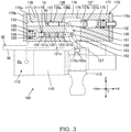
- the control pressure regulating valve 120 includes a control pressure regulating spool 121, and an accommodating hole 175 (see FIG. 3 ) which accommodates the control pressure regulating spool 121.
- the control pressure regulating valve 120 includes a pump port 123 connected to the discharge passage 11, a tank port 124 connected to the tank 19 through a drain passage, and a control pressure port 125 connected to a large diameter side chamber 113 described later through a control pressure passage 12.
- the control pressure regulating valve 120 has a pump communication position, an interruption position, and a tank communication position.
- the pump communication position is a position where the pump port 123 and the control pressure port 125 communicate with each other, and the communication between the tank port 124 and the control pressure port 125 is interrupted.
- the tank communication position is a position where the tank port 124 and the control pressure port 125 communicate with each other, and the communication between the pump port 123 and the control pressure port 125 is interrupted.
- the interruption position is a position where the communication between the pump port 123 and the control pressure port 125 is interrupted, and the communication between the tank port 124 and the control pressure port 125 is interrupted.
- the control pressure regulating valve 120 further includes: a spring 126 serving as a biasing member for biasing the control pressure regulating spool 121 in a direction for changing the position from the pump communication position to the tank communication position; and a connecting portion 127 which is connected to a feedback lever 150.
- the servo piston 110 is connected to the swash plate 15, and the tilt angle of the swash plate 15 is changed corresponding to the movement of the servo piston 110.
- the servo piston 110 has a large diameter portion 111 formed on one end side of the servo piston 110 in the axial direction, and a small diameter portion 112 formed on the other end side of the servo piston 110 in the axial direction.
- An outer diameter of the large diameter portion 111 is larger than an outer diameter of the small diameter portion 112.
- the large diameter side chamber 113 being a pressure chamber that the large diameter portion 111 of the servo piston 110 faces, and a small diameter side chamber 114 being a pressure chamber that the small diameter portion 112 of the servo piston 110 faces are formed.
- a pressure receiving surface area of the servo piston 110 on which a pressure in the large diameter side chamber 113 acts is larger than a pressure receiving surface area of the servo piston 110 on which a pressure in the small diameter side chamber 114 acts.
- the large diameter side chamber 113 is connected to the control pressure port 125 of the control pressure regulating valve 120 through the control pressure passage 12, and the small diameter side chamber 114 is connected to the discharge passage 11 of the pump 10.
- control pressure regulating valve 120 When the control pressure regulating valve 120 is switched to the pump communication position, a working oil is introduced into the large diameter side chamber 113 through the control pressure regulating valve 120 so that a pressure in the large diameter side chamber 113 rises.
- the control pressure regulating valve 120 When the control pressure regulating valve 120 is switched to the tank communication position, the working oil is discharged from the large diameter side chamber 113 into the tank 19 through the control pressure regulating valve 120 so that the pressure in the large diameter side chamber 113 is lowered.
- the control pressure regulating valve 120 When the control pressure regulating valve 120 is switched to the interruption position, the pressure in the large diameter side chamber 113 is maintained at a certain pressure.
- control pressure Pc the pressure in the large diameter side chamber 113 regulated by the displacement of the control pressure regulating spool 121 is referred to as "control pressure Pc".
- the pump displacement control device 100 further includes the feedback lever 150 which is connected to the servo piston 110 and the control pressure regulating spool 121.
- the feedback lever 150 feedbacks the displacement of the servo piston 110 to the control pressure regulating spool 121.
- the servo piston 110 is connected to the control pressure regulating spool 121 by way of the feedback lever 150.
- a feedback control where the displacement of the control pressure regulating valve 120 is regulated corresponding to the tilt angle of the pump 10 is performed.
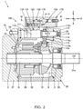
- the pump 10 includes: a cylinder block 32 which is rotatably driven by the engine 5 (see FIG. 1 ); pistons 33 which move in a reciprocating manner in a plurality of cylinders 34 disposed in the cylinder block 32; and the swash plate 15 which the pistons 33 follow.
- the cylinder block 32 and the swash plate 15 are housed in the pump housing 30.
- the pump housing 30 includes a cylindrical body portion 38, a pump base 37 which closes an opening formed on one end side of the body portion 38, and a pump cover 39 which closes an opening formed on the other end side of the body portion 38.
- a shaft 31 is fixedly mounted in the cylinder block 32.
- a proximal end portion 31a of the shaft 31 is connected to an output shaft of the engine 5 (see FIG. 1 ).
- a distal end portion of the shaft 31 is rotatably supported on the pump base 37 by way of a bearing 2, and a center portion of the shaft 31 is rotatably supported on the pump cover 39 by way of a bearing 3.
- the swash plate 15 is swingably supported on the pump housing 30 by way of a tilt bearing 9.
- strokes of the pistons 33 with respect to the cylinders 34 change so that the pump displacement changes.
- the structure of the pump displacement control device 100 is described in detail with reference to FIG. 2 to FIG. 5 .
- an X axis, a Y axis and a Z axis are defined as illustrated in the drawings.
- the X axis, the Y axis and the Z axis are orthogonal to each other. Further, a direction parallel to the X axis is expressed as an X axis direction, a direction parallel to the Y axis is expressed as a Y axis direction, and a direction parallel to the Z axis is expressed as a Z axis direction.
- the X axis is an axis parallel to a rotation center axis CO of the cylinder block 32.
- the Y axis is an axis parallel to a swinging center axis of the swash plate 15.
- One X axis direction directed toward a pump cover 39 side from a pump base 37 side is expressed as +X direction
- the other X axis direction which is a direction opposite to +X direction is expressed as -X direction.
- a piston housing portion 118 which slidably houses the servo piston 110 is formed in the body portion 38 of the pump housing 30.
- the servo piston 110 is disposed parallel to the X axis, and slides in the piston housing portion 118 in the X axis direction.
- a connecting member 115 is mounted on the servo piston 110.
- the connecting member 115 includes: a cylindrical fastening portion 115a fastened to the servo piston 110 by screws; a protruding portion 115b protruding in one Z axis direction (downward in the drawing) from the fastening portion 115a; and a connecting groove 115c disposed on a side opposite to the protruding portion 115b.
- the protruding portion 115b is slidably and rotatably connected to the connecting groove 15a formed in the swash plate 15.
- one end portion of the feedback lever 150 is slidably and rotatably connected to the connection groove 115c of the connecting member 115. Since the feedback lever 150 is connected to the connecting portion 127 of the control pressure regulating spool 121, when the servo piston 110 moves, a drive force of the servo piston 110 is transmitted to the control pressure regulating spool 121 by way of the feedback lever 150 and hence, the control pressure regulating spool 121 also moves. The detail of the structure of the feedback lever 150 is described later.
- the pump displacement control device 100 includes a regulator housing 170 mounted on the body portion 38 of the pump housing 30.
- the flow rate control mechanism 130, the power control mechanism 140 (see FIG. 4A ) and the control pressure regulating valve 120 are disposed in the regulator housing 170.
- the regulator housing 170 includes a body portion 170a having a rectangular parallelepiped shape, and covers (a first cover 170b and a second cover 170c) having a rectangular flat plate shape which are mounted on both ends of the body portion 170a.
- a housing chamber 179 which opens on a mounting surface of the pump housing 30, and a plurality of housing portions (a first housing hole 171, a second housing hole 172, a third housing hole 173, a fourth housing hole 174, and a fifth housing hole 175) are formed.
- the respective housing holes 171 to 175 are formed in the X axis direction in a penetrating manner. That is, the respective housing holes 171 to 175 open in the housing chamber 179, and open on end surfaces of the body portion 170a.
- the first housing hole 171 and the second housing hole 172 are housing portions in which a flow rate control spool 131 described later is housed, and the first housing hole 171 and the second housing hole 172 have coaxial circular cross-sections respectively.
- the third housing hole 173 and the fourth housing hole 174 are housing portions in which a power control spool 141 described later is housed, and the third housing hole 173 and the fourth housing hole 174 have coaxial circular cross sections respectively.
- the fifth housing hole 175 is a housing portion in which the control pressure regulating spool 121 is housed.
- the housing chamber 179 is a housing portion in which the feedback lever 150 is housed. Openings of the respective housing holes 171 to 175 formed on the end surfaces of the body portion 170a are closed by the covers 170b, 170c, plugs and the like.
- the housing chamber 179 in the body portion 170a is formed such that the housing chamber 179 faces the connecting groove 115c of the servo piston 110.
- the housing chamber 179 in the body portion 170a is formed such that the housing chamber 179 faces the swash plate 15 (see FIG. 2 ) with the servo piston 110 sandwiched between the housing chamber 179 and the swash plate 15.
- a portion of the body portion 170a on a -X direction side with respect to the housing chamber 179 is referred to as a first block 176
- a portion of the body portion 170a on a +X direction side with respect to the housing chamber 179 is referred to as a second block 177.
- the body portion 170a is divided into the first block 176 and the second block 177 by the housing chamber 179, and the first block 176 and the second block 177 are connected to each other by a connecting block 178.
- the flow rate control mechanism 130 includes: a pressure chamber 133 into which the input pressure Pi is introduced from the electromagnetic proportional control valve 21 (see FIG. 1 ) through an input pressure passage 13; the flow rate control spool 131 which shifts corresponding to the input pressure Pi; and a spring 132 serving as a biasing member for biasing the flow rate control spool 131 against a pressure in the pressure chamber 133.
- the flow rate control spool 131 is disposed parallel to the X axis.
- One end side (a left end side in the drawing) of the flow rate control spool 131 is slidably housed in the first housing hole 171 formed in the first block 176 of the regulator housing 170.
- the other end side (a right end side in the drawing) of the flow rate control spool 131 is slidably housed in the second housing hole 172 formed in the second block 177 of the regulator housing 170.
- a spring 132 is disposed in the second housing hole 172.
- the pressure chamber 133 is formed by the first housing hole 171, the first cover 170b, and the flow rate control spool 131.
- the flow rate control spool 131 is disposed such that one end portion in the axial direction (a left end portion in the drawing) of the flow rate control spool 131 faces the pressure chamber 133. Accordingly, the input pressure Pi outputted from the electromagnetic proportional control valve 21 acts on one end portion (the left end portion in the drawing) of the flow rate control spool 131.
- the flow rate control spool 131 is divided into a first piece 136 and a second piece 137 in the axial direction of the flow rate control spool 131.
- the first piece 136 includes: a land portion 136a which slides in the first housing hole 171; and a circular columnar portion 136b which extends from the land portion 136a toward the second piece 137 in the axial direction.
- the second piece 137 includes: a spring receiving portion 137a on which an end portion of the spring 132 abuts; and a circular columnar portion 137b which extends from the spring receiving portion 137a toward the first piece 136 in the axial direction.
- the first piece 136 is biased in the +X direction by a pressure (input pressure Pi) of a working oil in the pressure chamber 133.
- the second piece 137 is biased in the -X direction by an elastic force of the spring 132.
- a stepped portion which abuts on the spring receiving portion 137a is formed in the second housing hole 172, and the stepped portion restricts the movement of the second piece 137 in the -X direction.
- the flow rate control spool 131 moves in the axial direction while maintaining a state where the circular columnar portion 136b of the first piece 136 and the circular columnar portion 137b of the second piece 137 abut on each other.
- an outer diameter of the circular columnar portion 136b of the first piece 136 is smaller than an outer diameter of the circular columnar portion 137b of the second piece 137. Accordingly, a stepped portion 138 is formed between the circular columnar portion 136b and the circular columnar portion 137b.
- the stepped portion 138 is a portion which abuts on a first contact portion 151a of the feedback lever 150 described later.
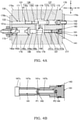
- the power control mechanism 140 includes: a first pressure chamber 143 into which the discharge pressure P1 in the pump 10 is introduced; a second pressure chamber 144 into which the discharge pressure P2 in another pump (not shown) different from the pump 10 is introduced; the power control spool 141 which shifts corresponding to the discharge pressure P1 and the discharge pressure P2; and springs 142a, 142b serving as biasing members for biasing the power control spool 141 against pressures in the first pressure chamber 143 and the second pressure chamber 144.
- the power control spool 141 is disposed parallel to the X axis.
- One end side (the left end side in the drawing) of the power control spool 141 is slidably housed in the third housing hole 173 formed in the first block 176 of the regulator housing 170.
- the other end side (the right end side in the drawing) of the power control spool 141 is slidably housed in a sleeve 181 mounted in the fourth housing hole 174 formed in the second block 177 of the regulator housing 170.
- the springs 142a, 142b are disposed in the third housing hole 173.
- the power control spool 141 includes a large diameter portion 147a, and a small diameter portion 147b having a smaller outer diameter than the large diameter portion 147a.
- a stepped portion 141c is formed between the large diameter portion 147a and the small diameter portion 147b.
- a slide hole in which the large diameter portion 147a slides and a slide hole in which the small diameter portion 147b slides are formed in the sleeve 181.
- the first pressure chamber 143 is formed by the sleeve 181, the stepped portion 141c, and the small diameter portion 147b.
- the second pressure chamber 144 is formed by the sleeve 181 and the small diameter portion 147b.
- the power control spool 141 is disposed such that the stepped portion 141c faces the first pressure chamber 143, and the small diameter portion 147b faces the second pressure chamber 144. Accordingly, the discharge pressure P1 of the pump 10 acts on the stepped portion 141c between the large diameter portion 147a and the small diameter portion 147b of the power control spool 141.
- the discharge pressure P2 of another pump which is a pump different from the pump 10 acts on the small diameter portion 147b of the power control spool 141.
- the power control spool 141 is divided into a first piece 146 and a second piece 147 in an axial direction of the power control spool 141.
- the first piece 146 includes: a slide portion 146a which slides in the third housing hole 173; a circular columnar portion 146b which extends from the slide portion 146a toward the second piece 147 in the axial direction; and a spring receiving portion 146c on which end portions of the springs 142a, 142b abut.
- the second piece 147 includes: a circular plate portion 147c disposed in the housing chamber 179; a large diameter portion 147a which extends from the circular plate portion 147c in the +X direction; and a small diameter portion 147b which extends from the large diameter portion 147a in the +X direction.
- An outer diameter of the circular plate portion 147c is larger than an opening diameter of the sleeve 181.
- the circular plate portion 147c abuts on an end portion of the sleeve 181 so as to restrict the movement of the second piece 147 in the +X direction.
- the second piece 147 is biased in the -X direction by a pressure (discharge pressure PI) of a working oil in the first pressure chamber 143 and a pressure (discharge pressure P2) of a working oil in the second pressure chamber 144.
- the second piece 137 is biased in the +X direction by elastic forces of the springs 142a, 142b.
- a stepped portion which abuts on the spring receiving portion 146c is formed in the third housing hole 173, and the stepped portion restricts the movement of the first piece 146 in the +X direction.
- the power control spool 141 moves in the axial direction while maintaining a state where the circular columnar portion 146b of the first piece 146 and the circular plate portion 147c of the second piece 147 abut on each other.
- An outer diameter of the circular columnar portion 146b of the first piece 146 is smaller than an outer diameter of the circular plate portion 147c of the second piece 147. Accordingly, a stepped portion 148 is formed between the circular columnar portion 146b and the circular plate portion 147c.
- the stepped portion 148 is a portion which abuts on a second contact portion 151b of the feedback lever 150 described later.
- control pressure regulating spool 121 of the control pressure regulating valve 120 is disposed parallel to the X axis.
- the control pressure regulating spool 121 is slidably housed in the fifth housing hole 175 formed in the first block 176 of the regulator housing 170.
- a retainer 182 is mounted on an end portion of the fifth housing hole 175 on a first cover 170b side.
- the spring 126 is disposed between the retainer 182 and the control pressure regulating spool 121.
- the control pressure regulating spool 121 is biased by the spring 126 in the direction toward the housing chamber 179 (+X direction).
- the control pressure regulating valve 120 has a drain chamber 129 which communicates with the tank 19.
- the drain chamber 129 is formed by an end portion of the control pressure regulating spool 121 on a -X direction side, the fifth housing hole 175, and the retainer 182.
- the above-mentioned spring 126 is housed in the drain chamber 129.
- the tank port 124 is formed in the control pressure regulating spool 121.
- the drain chamber 129 communicates with the housing chamber 179 through the tank port 124 of the control pressure regulating spool 121.
- the housing chamber 179 communicates with the tank 19 through a drain passage (not illustrated in the drawing) formed in the pump housing 30.
- the control pressure regulating spool 121 has a first land portion 121a and a second land portion 121b which slide in the fifth housing hole 175.
- the first land portion 121a is formed with a size which allows the first land portion 121a to close the control pressure port 125.
- the second land portion 121b is formed on a housing chamber 179 side with respect to the first land portion 121a.
- An annular groove 121c is formed between the first land portion 121a and the second land portion 121b.
- the pump port 123 or the tank port 124 selectively communicates with the control pressure port 125 so that the control pressure Pc in the large diameter side chamber 113 is regulated.
- the control pressure regulating spool 121 has the connecting portion 127 which extends in the axial direction from the second land portion 121b toward a housing chamber 179 side.
- the connecting portion 127 protrudes into the housing chamber 179 from the second land portion 121b, and a protruding end portion of the connecting portion 127 is rotatably connected to the feedback lever 150.
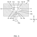
- the feedback lever 150 includes a body portion 152 which is a rod-like member, a connecting pin 153 and a contact pin 151.
- the connecting pin 153 and the contact pin 151 are fixed to the body portion 152.
- a connecting portion 152a which is connected to the connecting groove 115c formed on the servo piston 110 is formed on one end portion in the axial direction (lower end portion illustrated in FIG. 5 ) of the body portion 152 of the feedback lever 150.
- the contact pin 151 serving as a contact portion selectively abutting on either the flow rate control spool 131 or the power control spool 141 is fixed to the other end portion in the axial direction (upper end portion in FIG.
- the connecting pin 153 serving as a connecting portion connected to the control pressure regulating spool 121 is fixed to a center portion in the axial direction of the body portion 152 of the feedback lever 150.
- An insertion hole 152b is formed in a center portion in the axial direction of the body portion 152 of the feedback lever 150 in a penetrating manner in the X axis direction.
- the connecting portion 127 of the control pressure regulating spool 121 is allowed to pass through the insertion hole 152b.
- the connecting pin 153 is inserted into a through hole which is formed in the feedback lever 150 in a penetrating manner in the Y axis direction.
- the connecting portion 127 of the control pressure regulating spool 121 is formed in a shape where a distal end of the connecting portion 127 is bifurcated in a U shape, and the connecting pin 153 is rotatably connected to a recessed portion of the connecting portion 127.
- the contact pin 151 is allowed to pass through a through hole which is formed in the body portion 152 of the feedback lever 150 in a penetrating manner in the Y axis direction, and forms a portion of the feedback lever 150.
- the contact pin 151 includes: the first contact portion 151a which protrudes from the through hole toward a flow rate control spool 131 side; and the second contact portion 151b which protrudes from the through hole toward a power control spool 141 side.
- the first contact portion 151a is disposed such that an outer peripheral surface (side surface) of the first contact portion 151a faces the stepped portion 138 of the flow rate control spool 131.
- the second contact portion 151b is disposed on a side opposite to the first contact portion 151a, and an outer peripheral surface (side surface) of the second contact portion 151b faces the stepped portion 148 of the power control spool 141.
- the flow rate control spool 131 and the power control spool 141 are disposed such that the flow rate control spool 131 and the power control spool 141 are disposed parallel to the servo piston 110, and face each other with the other end portion in the axial direction (upper end portion illustrated in FIG. 5 ) of the feedback lever 150 sandwiched between the flow rate control spool 131 and the power control spool 141 in the direction (Y axis direction) orthogonal to the servo piston 110.
- the flow rate control spool 131, the other end portion in the axial direction (the upper end portion illustrated in FIG. 5 ) of the feedback lever 150, and the power control spool 141 are disposed in an overlapping manner.
- the flow rate control spool 131 and the power control spool 141 are disposed such that the flow rate control spool 131 and the power control spool 141 are each disposed parallel to the servo piston 110, and face each other with the feedback lever 150 sandwiched in the radial direction between the flow rate control spool 131 and the power control spool 141. Accordingly, compared to a case where the respective spools 131, 141 are disposed on one straight line such that the flow rate control spool 131 and the power control spool 141 are disposed coaxially, the miniaturization of the pump displacement control device 100 in the axial direction can be realized.
- the position of the flow rate control spool 131 is set by a force which pushes the flow rate control spool 131 in the +X direction by a working oil having the input pressure Pi and a force which pushes the flow rate control spool 131 in the -X direction by the spring 132.
- the input pressure Pi is lower than a predetermined pressure, as illustrated in FIG. 3 and FIG. 4A , the flow rate control spool 131 is positioned at an initial position where the spring receiving portion 137a abuts on the stepped portion of the second housing hole 172.
- the first contact portion 151a of the feedback lever 150 abuts on the stepped portion 138 of the flow rate control spool 131. Accordingly, the feedback lever 150 is pushed in the -X direction by the flow rate control spool 131.
- the control pressure regulating spool 121 is connected to the feedback lever 150, and the control pressure regulating spool 121 is pushed in the +X direction by the spring 126. Accordingly, the feedback lever 150 is pushed in the -X direction by the flow rate control spool 131 and, at the same time, is pushed in the +X direction by the control pressure regulating spool 121.
- the position of the power control spool 141 is set by a force which pushes the power control spool 141 in the -X direction by a working oil having the discharge pressure P1 and the working oil having the discharge pressure P2, and a force which pushes the power control spool 141 in the +X direction by the springs 142a, 142b.
- the power control spool 141 is, as illustrated in FIG. 4A , positioned at an initial position where the spring receiving portion 146c abuts on the stepped portion of the third housing hole 173.
- the stepped portion 148 of the power control spool 141 and the second contact portion 151b of the feedback lever 50 are spaced apart from each other by a distance X1 (0 ⁇ X1). That is, the second contact portion 151b of the feedback lever 150 does not abut on the stepped portion 148 of the power control spool 141.
- the feedback lever 150 is pushed in the -X direction by the flow rate control spool 131 and hence, the control pressure regulating spool 121 is pushed in the -X direction by the feedback lever 150. Accordingly, as illustrated in FIG. 3 , the control pressure regulating spool 121 is maintained at the pump communication position where the pump port 123 and the control pressure port 125 communicate with each other through the annular groove 121c in the initial state.
- a pressure (control pressure Pc) in the large diameter side chamber 113 is equal to the discharge pressure P1 of the pump 10.
- the servo piston 110 is positioned at an initial position where the small diameter portion 112 abuts on a plug 35 which closes the opening of the piston housing portion 118, and sets the tilt angle of the swash plate 15 such that the pump displacement becomes a minimum value.
- the flow rate control spool 131 stops at a position where a force which pushes the flow rate control spool 131 in the +X direction by a working oil of the input pressure Pi and a force which pushes the flow rate control spool 131 in the -X direction by the spring 132 are balanced.
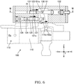
- the feedback lever 150 rotates in an R2 direction (clockwise direction in the drawing) about an upper side fulcrum 61 (see also FIG. 7 ) which is a contact point between the first contact portion 151a of the feedback lever 150 and the stepped portion 138 of the flow rate control spool 131.
- the control pressure regulating spool 121 is moved by pushing in the -X direction by the feedback lever 150.
- control pressure regulating spool 121 When the control pressure regulating spool 121 is switched to the pump communication position with such a manipulation, a pressure (control pressure Pc) of the large diameter side chamber 113 is increased and hence, the servo piston 110 moves in the +X direction again and the tilt angle of the swash plate 15 is decreased. That is, the pump displacement is decreased.
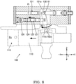
- the servo piston 110 repeats the operation where the control pressure regulating spool 121 is switched between the pump communication position and the tank communication position until the pump displacement takes a value corresponding to a manipulation variable of the manipulation lever (hereinafter referred to as a target value).
- a target value a manipulation variable of the manipulation lever
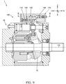
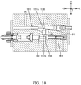
- FIG. 9 and FIG. 10 illustrate a state where the pump displacement becomes maximum.
- the feedback lever 150 does not abut on the power control spool 141. That is, the second contact portion 151b of the feedback lever 150 and the stepped portion 148 of the power control spool 141 are spaced apart from each other by a distance X2 (0 ⁇ X2 ⁇ X1).
- the operation of the pump device 1 when the power control is performed is described.
- the power control spool 141 moves in the -X direction, and the stepped portion 148 of the power control spool 141 abuts on the second contact portion 151b of the feedback lever 150.
- the control pressure regulating spool 121 is moved by pushing in the -X direction.
- the flow rate control spool 131 and the first contact portion 151a of the feedback lever 150 are spaced apart from each other.
- the feedback lever 150 feedbacks the displacement of the servo piston 110 to the control pressure regulating spool 121.
- the flow rate control is performed in a state where the first contact portion 151a serving as a portion of the feedback lever 150 and the stepped portion 138 of the flow rate control spool 131 abut on each other.
- the displacement of the flow rate control spool 131 is transmitted to the control pressure regulating spool 121 by way of the feedback lever150 and hence, a control pressure Pc is regulated corresponding to the displacement of the flow rate control spool 131.
- the discharge pressures PI, P2 are increased, the second contact portion 151b serving as a portion of the feedback lever 150 and the stepped portion 148 of the power control spool 141 abut on each other and hence, the flow rate control is switched to the power control.
- the displacement of the power control spool 141 is transmitted to the control pressure regulating spool 121 by way of the feedback lever 150 so that the control pressure Pc is regulated corresponding to the displacement of the power control spool 141.
- the tilt angle of the swash plate 15 is controlled such that the pump displacement becomes lower than the target value of the pump displacement corresponding to a control current set by the controller 20.
- a control pressure Pc is regulated in such a manner that the feedback lever 150 directly abuts on either one of the flow rate control spool 131 or the power control spool 141 not by way of an additional member such as a lever. Accordingly, an operation of the flow rate control spool 131 and an operation of the power control spool 141 are speedily transmitted to the control pressure regulating spool 121 by way of the feedback lever 150 and hence, an operation responsiveness of the control pressure regulating spool 121 can be enhanced. As a result, the displacement of the pump 10 can be properly controlled.
- the simple configuration is adopted where the flow rate control spool 131 and the power control spool 141 directly abut on the feedback lever 150 and hence, a cost of the pump displacement control device 100 can be reduced. That is, in the present embodiment, the pump displacement control device 100 which can properly control the displacement of the pump 10 can be provided at a low cost.
- the control pressure regulating spool 121 regulates a control pressure Pc for controlling the servo piston 110 corresponding to the displacement of one spool which decreases the displacement of the pump 10 out of the flow rate control spool 131 and the power control spool 141. Accordingly, when discharge pressures PI, P2 of the pump 10 are increased in a state where the flow rate control is being performed, the power control is performed in place of the flow rate control and the tilt angle of the pump 10 is decreased and hence, an overload applied to a drive source (engine 5) of the pump 10 can be prevented.
- the present invention is not limited to such an embodiment.
- a negative flow rate control in which the displacement of the pump 10 is decreased in proportion to the increase of the input pressure Pi may be performed.
- the arrangement relationship between the pressure chamber 133 and the spring 132 provided for biasing the flow rate control spool 131 may be set opposite to the corresponding arrangement relationship in the above-mentioned embodiment. That is, the spring 132 is disposed in the first housing hole 171 in the above-mentioned embodiment, and the input pressure Pi is introduced into the second housing hole 172 in the above-mentioned embodiment.
- the configuration is adopted where the flow rate control spool 131 is biased in the +X direction by a pressure (input pressure Pi) of a working oil in the pressure chamber 133 and the flow rate control spool 131 is biased in the -X direction by an elastic force of the spring 132.
- the input pressure Pi rises in a state where the displacement of the pump 10 is minimum
- the flow rate control spool 131 moves in the +X direction
- the control pressure regulating spool 121 moves in the +X direction so that a working oil is discharged from the large diameter side chamber 113 to the tank 19 through the control pressure regulating valve 120 whereby a control pressure Pc is lowered.
- the control pressure Pc is lowered, the servo piston 110 moves in the -X direction so that the tilt angle of the swash plate 15 is increased. That is, the pump displacement is increased.
- the configuration is adopted where the flow rate control spool 131 is biased in the -X direction by a pressure (input pressure Pi) of a working oil in the pressure chamber 133, and is biased in the +X direction by an elastic force of the spring 132. Accordingly, when the input pressure Pi is lowered in a state where the displacement of the pump 10 is minimum, the flow rate control spool 131 moves in the +X direction and the control pressure regulating spool 121 moves in the +X direction so that a working oil is discharged from the large diameter side chamber 113 to the tank 19 through the control pressure regulating valve 120 whereby a control pressure Pc is lowered. When the control pressure Pc is lowered, the servo piston 110 moves in the -X direction so that the tilt angle of the swash plate 15 is increased. That is, the pump displacement is increased.
- the flow rate control spool 131 and the power control spool 141 are disposed such that the flow rate control spool 131 and the power control spool 141 are each disposed parallel to the servo piston 110, and face each other with the feedback lever 150 sandwiched between the flow rate control spool 131 and the power control spool 141.
- the pump 10 may be a swash-axis-type piston pump where the displacement of the pump 10 is defined by controlling a tilt angle of a swash axis.
- the present invention is not limited to such an example.
- a pilot pressure outputted corresponding to a manipulation variable of a manipulation lever manipulated by an operator may be used as the input pressure Pi.
- the electromagnetic proportional control valve 21 can be omitted.
- the first contact portion 151a and the second contact portion 151b may be formed on the feedback lever 150 by integral molding. That is, the feedback lever 150 which has the first contact portion 151a and the second contact portion 151b may be formed as a single part.
- the arrangement relationship between the first contact portion 151a and the second contact portion 151b is not limited to the above-mentioned embodiment.
- the first contact portion 151a is disposed, in the same manner as the above-mentioned embodiment, orthogonal to the body portion 152 of the feedback lever 150, and the second contact portion 151b may be disposed such that the second contact portion 151b extends from a distal end of the feedback lever 150 in the axial direction.
- the pump displacement control device 100 has the configuration where the feedback lever 150 directly abuts on one spool which decreases the displacement of the pump 10 out of the flow rate control spool 131 and the power control spool 141.
- the contact portion between the spool and the feedback lever 150 can be set at various positions.
- the present invention is not limited to such an example.
- the pump driven by the engine 5 is formed of only the pump 10 illustrated in FIG. 1
- the second pressure chamber 144 described in the above-mentioned embodiment can be omitted.
- the fifth housing hole 175 which houses the control pressure regulating spool 121 is disposed in a spaced apart manner from the first housing hole 171 which houses one end of the flow rate control spool 131 and the third housing hole 173 which houses one end of the power control spool 141 by a predetermined distance in the Z axis direction, and is disposed to be positioned substantially at the center between the first housing hole 171 and the third housing hole 173 in the Y axis direction.
- the fifth housing hole 175 which houses the control pressure regulating spool 121 is disposed in a spaced apart manner from the first housing hole 171 which houses one end of the flow rate control spool 131 and the third housing hole 173 which houses one end of the power control spool 141 by a predetermined distance in the Z axis direction, and is disposed to be positioned substantially at the center between the first housing hole 171 and the third housing hole 173 in the Y axis direction.
- the fifth housing hole 175 may be disposed such that the position of the fifth housing hole 175 in the Y axis direction is substantially aligned with the position of the first housing hole 171.
- FIG. 13 is a drawing illustrating the above-mentioned modification of the above-mentioned embodiment, and illustrates a cross section corresponding to the cross section illustrated in FIG. 5 .
- a feedback lever 250 in this modification includes a body portion 252 which is a rod-like member, a connecting pin 253, and a contact pin 251.
- a connecting portion 252a which is connected to the connecting groove 115c of the servo piston 110 is formed on one end portion in an axial direction (a lower end portion illustrated in FIG. 13 ) of the body portion 252.
- the contact pin 251 serving as a contact portion which selectively abuts on the flow rate control spool 131 or the power control spool 141 is fixed to the other end portion in the axial direction (an upper end portion illustrated in FIG. 13 ) of the body portion 252.
- the connecting pin 253 serving as a connecting portion which is connected to the control pressure regulating spool 121 is fixed to a center portion in the axial direction of the body portion 252.
- a through hole 252b is formed in a center portion in the axial direction of the body portion 252 of the feedback lever 250 in a penetrating manner in the Y axis direction.
- One end portion 253a of the connecting pin 253 is allowed to pass through the through hole 252b.
- the connecting portion 127 of the control pressure regulating spool 121 is formed in a U shape such that the distal end of the connecting portion 127 is bifurcated.
- the other end portion 253b of the connecting pin 253 protruding in the Y axis direction from the body portion 252 of the feedback lever 250 is rotatably connected to the recessed portion of the connecting portion 127.
- the contact pin 251 is allowed to pass through a through hole which penetrates the body portion 252 of the feedback lever 250 in the Y axis direction.
- the contact pin 251 includes: a first contact portion 251a which protrudes from the through hole toward the flow rate control spool 131 side; and a second contact portion 251b which protrudes from the through hole toward the power control spool 141 side.
- the feedback lever 250 may have a relatively simple shape where the contact pin 251 and the connecting pin 253 are allowed to pass through the body portion 252. Further, unlike the feedback lever 150 of the above-mentioned embodiment, it is unnecessary to form the insertion hole 152b which penetrates in the X axis direction in the feedback lever 250. Accordingly, working and assembling of the feedback lever 250 can be facilitated. As a result, a manufacturing cost of the pump displacement control device 100 can be reduced.
- the other end portion 253b of the connecting pin 253 extends toward a first housing hole 171 side and hence, the position of the fifth housing hole 175 in the Y axis direction is substantially aligned with the first housing hole 171.
- the other end portion 253b of the connecting pin 253 may extend toward a third housing hole 173 side, and the position of the fifth housing hole 175 in the Y axis direction may be substantially aligned with the third housing hole 173.
- the position at which the fifth housing hole 175 is disposed in the Y axis direction is on an extension line of the connecting pin 253, and the connecting portion 127 of the control pressure regulating spool 121 can be connected to the connecting pin 253.
- a length of the other end portion 253b of the connecting pin 253 is elongated thus giving rise to a concern that the displacement of the control pressure regulating spool 121 is not accurately transmitted to the feedback lever 250.
- the position at which the fifth housing hole 175 is disposed is preferably the position close to the body portion 252 of the feedback lever 250, for example, the position between the first housing hole 171 and the third housing hole 173 in the Y axis direction.
- the position of the fifth housing hole 175 can be suitably changed in conformity with the layout of the passages and the housing holes formed in the regulator housing 170. Accordingly, the degree of freedom in designing the pump displacement control device 100 can be enhanced.
- the pump displacement control device 100 is a pump displacement control device for controlling the displacement of the pump 10.
- the pump displacement control device 100 includes: the servo piston 110 configured to change the tilt angle of the pump 10; the flow rate control spool 131 configured to be displaced corresponding to the input pressure Pi; the power control spool 141 configured to be displaced corresponding to discharge pressures PI, P2 of the pump 10; the control pressure regulating spool 121 configured to regulate a control pressure Pc which controls the servo piston 110 corresponding to a displacement of the flow rate control spool 131 and a displacement of the power control spool 141; and the feedback lever 150 connected to the servo piston 110 and the control pressure regulating spool 121, and configured to feedback a displacement of the servo piston 110 to the control pressure regulating spool 121, wherein the feedback lever 150 is configured to directly abut on either one of the flow rate control spool 131 or the power control spool 141 so as to regulate the control pressure Pc.
- the feedback lever 150 directly abuts on either one of the flow rate control spool 131 or the power control spool 141 not by way of an additional member such as a lever. Accordingly, the operation of the flow rate control spool 131 and the operation of the power control spool 141 are speedily transmitted to the control pressure regulating spool 121 by way of the feedback lever 150 and hence, an operational responsiveness of the control pressure regulating spool 121 can be enhanced. As a result, the displacement of the pump 10 can be properly controlled. Further, the simple configuration is adopted where the flow rate control spool 131 and the power control spool 141 directly abut on the feedback lever 150 and hence, a cost of the pump displacement control device 100 can be reduced. That is, according to such a configuration, it is possible to provide the pump displacement control device 100 capable of properly control the displacement of the pump 10 at a low cost.
- the feedback lever 150 includes: the first contact portion 151a configured to abut on the stepped portion 138 of the flow rate control spool 131; and the second contact portion 151b disposed on a side opposite to the first contact portion 151a and configured to abut on the stepped portion 148 of the power control spool 141, wherein the flow rate control spool 131 and the power control spool 141 are disposed such that the flow rate control spool 131 and the power control spool 141 are each disposed parallel to the servo piston 110, and face each other with the feedback lever 150 sandwiched between the flow rate control spool 131 and the power control spool 141.
- the flow rate control spool 131 and the power control spool 141 are disposed such that the flow rate control spool 131 and the power control spool 141 are each disposed parallel to the servo piston 110, and face each other with the feedback lever 150 sandwiched between the flow rate control spool 131 and the power control spool 141. Accordingly, compared to a case where the flow rate control spool 131 and the power control spool 141 are disposed coaxially, the miniaturization of the pump displacement control device 100 in the axial direction can be realized.
- control pressure regulating spool 121 is configured to regulate a control pressure Pc corresponding to the displacement of one spool which decreases the displacement of the pump 10 out of the flow rate control spool 131 and the power control spool 141.
Landscapes
- Engineering & Computer Science (AREA)
- Mechanical Engineering (AREA)
- General Engineering & Computer Science (AREA)
- Control Of Positive-Displacement Pumps (AREA)
- Reciprocating Pumps (AREA)
Abstract
Description
- The present invention relates to a pump displacement control device.
- There has been known a pump displacement control device which controls displacement of a pump by changing a tilt angle of a variable displacement pump (see
JP H01-116294A JP H01-116294A - The pilot spool mechanism for the flow rate control is a mechanism which performs the flow rate control for controlling a displacement of the pump on the basis of an external pilot pressure. The pilot spool mechanism for the power control is a mechanism which performs the power control and decreases the displacement of the pump along with the increase of a discharge pressure of the pump. The power control is a control performed for preventing an engine stall by controlling the displacement of the pump so that power necessary for driving the pump does not exceed an output of an engine which is a drive source of the pump.
- The pump displacement control device described in
JP H01-116294A - In the pump displacement control device described in
JP HO 1-116294A JP H01-116294A - It is an object of the present invention to provide a pump displacement device which can properly control a displacement of a pump and can be manufactured at a low cost.
- According to one aspect of the present invention, a pump displacement control device for controlling a displacement of a pump includes: a servo piston configured to change a tilt angle of the pump; a flow rate control spool configured to be displaced corresponding to an input pressure; a power control spool configured to be displaced corresponding to a discharge pressure of the pump; a control pressure regulating spool configured to regulate a control pressure which controls the servo piston corresponding to a displacement of the flow rate control spool and a displacement of the power control spool; and a feedback lever connected to the servo piston and the control pressure regulating spool, the feedback lever being configured to feedback a displacement of the servo piston to the control pressure regulating spool. The feedback lever is configured to directly abut on either one of the flow rate control spool or the power control spool for regulating the control pressure.
-
-
FIG. 1 is a hydraulic circuit diagram illustrating the configuration of a pump device provided with a pump displacement control device according to the present embodiment, -
FIG. 2 is a cross-sectional view of the pump device illustrating a state where a displacement of a pump is minimum, -
FIG. 3 is a view illustrating the pump displacement control device inFIG. 2 in an enlarged manner, -
FIG. 4A is a cross-sectional view taken along a line IV-IV inFIG. 2 , -
FIG. 4B is a partially enlarged view ofFIG. 4A illustrating a second piece of a power control spool, -
FIG. 5 is a cross-sectional view taken along a line V-V inFIG. 2 , -
FIG. 6 is a view for describing an operation of the pump displacement control device in a flow rate control state illustrating a state immediately after starting a manipulation of a lever, -
FIG. 7 is a cross-sectional view taken along a line VII-VII inFIG. 6 , -
FIG. 8 is a view for describing an operation of the pump displacement control device in a flow rate control state illustrating an operation in which a displacement of a servo piston is fed back to a control pressure regulating spool by a feedback lever, -
FIG. 9 is a cross-sectional view of the pump device illustrating a state where the displacement of the pump is maximum, -
FIG. 10 is a cross-sectional view taken along a line X-X inFIG. 9 , -
FIG. 11 is a view for describing an operation of the pump displacement control device in a power control state, -
FIG. 12 is a hydraulic circuit diagram illustrating the configuration of a pump device provided with a pump displacement control device according to a modification of the present embodiment, -
FIG. 13 is a cross-sectional view illustrating a pump displacement control device according to a modification of present embodiment and corresponds toFIG. 5 . - Pump displacement control devices according to embodiments of the present invention are described with reference to drawings.
- The pump displacement control device is a device which controls displacement (displacement volume) by changing a tilt angle of a variable displacement pump.
-
FIG. 1 is a hydraulic circuit diagram illustrating the configuration of apump device 1 provided with a pumpdisplacement control device 100 according to the present embodiment. As illustrated inFIG. 1 , thepump device 1 includes avariable displacement pump 10, and the pumpdisplacement control device 100 which controls a displacement (displacement volume) of thepump 10. Displacement of thepump 10 is a discharge amount of a working fluid per one rotation of thepump 10. Hereinafter, displacement of thepump 10 is also referred to as "pump displacement". - In the
pump device 1 according to the present embodiment, a working oil is used as a working fluid. In place of a working oil, other working fluids such as working water and water soluble alternative liquid may be used. Thepump device 1 is provided as a pressure source of a hydraulic equipment mounted on a construction machine such as a hydraulic excavator. - The
pump 10 is a swash plate piston pump capable of changing the displacement corresponding to a tilt angle of aswash plate 15. Thepump 10 is rotatably driven by anengine 5 serving as a drive source. Thepump 10 sucks the working oil stored in atank 19, and discharges a pressurized working oil (pressurized oil) to adischarge passage 11. The working oil discharged from thepump 10 is supplied to a hydraulic equipment of a construction machine not illustrated in the drawing. Examples of the hydraulic equipment of the construction machine include a hydraulic cylinder which drives a boom, an arm, or a bucket of a hydraulic excavator, and a hydraulic motor which drives a crawler of a hydraulic excavator. - A
controller 20 which controls respective parts of the construction machine is mounted on the construction machine. Amanipulation sensor 22 which is a detection device adapted to detect a manipulation variable of a manipulation lever manipulated by an operator is connected to thecontroller 20. - The
controller 20 controls an electromagneticproportional control valve 21 on the basis of a detection result of themanipulation sensor 22. The electromagneticproportional control valve 21 decreases a pressure of the working oil supplied from anoil pressure source 18 corresponding to a control current from thecontroller 20, and outputs the pressure to the pumpdisplacement control device 100. The electromagneticproportional control valve 21 is, for example, a positive-proportional-type electromagnetic proportional control valve where the larger a control current which excites a solenoid becomes, the larger a secondary pressure outputted from the electromagneticproportional control valve 21 becomes. Hereinafter, the secondly pressure which is outputted from the electromagneticproportional control valve 21 and is inputted to the pumpdisplacement control device 100 is referred to as "input pressure Pi". - The
controller 20 controls a pump displacement on the basis of an manipulation variable of the manipulation lever which is detected by themanipulation sensor 22. In a memory part of thecontroller 20, a data table of control current values corresponding to manipulation variables of the manipulation lever is stored. Thecontroller 20 looks up the data table, and calculates a control current value corresponding to a manipulation variable of the manipulation lever. Thecontroller 20 controls the electromagneticproportional control valve 21 such that the larger a manipulation variable of the manipulation lever detected by themanipulation sensor 22 becomes, the larger a control current value with respect to the electromagneticproportional control valve 21 becomes. That is, thecontroller 20 controls the electromagneticproportional control valve 21 such that the larger a manipulation variable of the manipulation lever becomes, the larger a pump displacement becomes or the larger the input pressure Pi becomes. - The pump
displacement control device 100 is configured to perform a flow rate control where the displacement of thepump 10 is controlled on the basis of the input pressure Pi. In a flow rate control state, the pumpdisplacement control device 100 controls the tilt angle of theswash plate 15 of thepump 10 such that the larger the input pressure Pi becomes, the larger the displacement of thepump 10 becomes. - The pump
displacement control device 100 is also configured to perform a power control where the displacement of thepump 10 is controlled on the basis of a discharge pressure P1 of thepump 10 and a discharge pressure P2 of another pump driven by theengine 5. In the present embodiment, the power control is a control for preventing an engine stall where the displacement of the pump is controlled such that power necessary for driving the pumps (in this embodiment, thepump 10 driven by theengine 5 and the another pump different from the pump 10) does not exceed an output of theengine 5. In a power control state, the pumpdisplacement control device 100 controls the tilt angle of theswash plate 15 of thepump 10 such that the larger the discharge pressures PI, P2 become, the smaller the displacement of thepump 10 becomes. - The pump
displacement control device 100 selects the control where the displacement of thepump 10 becomes small out of the flow rate control and the power control, and performs the selected control. That is, the pumpdisplacement control device 100 performs the control where the displacement of thepump 10 becomes small with priority. Accordingly, in a case where a load pressure is increased when the flow rate control is undergoing, the power control is performed in place of the flow rate control so that the tilt angle of thepump 10 is decreased whereby an overload applied to theengine 5 can be prevented. Hereinafter, the pumpdisplacement control device 100 is described in detail. - The pump
displacement control device 100 includes: aservo piston 110 which is connected to theswash plate 15 of thepump 10 and changes the tilt angle of thepump 10; a controlpressure regulating valve 120 which regulates a control pressure Pc for controlling the displacement of theservo piston 110; a flowrate control mechanism 130 which is provided for performing the flow rate control for controlling the displacement of thepump 10 on the basis of the input pressure Pi; and apower control mechanism 140 provided for performing the power control for controlling the displacement of thepump 10 on the basis of discharge pressures PI, P2. - The control
pressure regulating valve 120 includes a controlpressure regulating spool 121, and an accommodating hole 175 (seeFIG. 3 ) which accommodates the controlpressure regulating spool 121. The controlpressure regulating valve 120 includes apump port 123 connected to thedischarge passage 11, atank port 124 connected to thetank 19 through a drain passage, and acontrol pressure port 125 connected to a largediameter side chamber 113 described later through acontrol pressure passage 12. - The control
pressure regulating valve 120 has a pump communication position, an interruption position, and a tank communication position. The pump communication position is a position where thepump port 123 and thecontrol pressure port 125 communicate with each other, and the communication between thetank port 124 and thecontrol pressure port 125 is interrupted. The tank communication position is a position where thetank port 124 and thecontrol pressure port 125 communicate with each other, and the communication between thepump port 123 and thecontrol pressure port 125 is interrupted. The interruption position is a position where the communication between thepump port 123 and thecontrol pressure port 125 is interrupted, and the communication between thetank port 124 and thecontrol pressure port 125 is interrupted. - The control
pressure regulating valve 120 further includes: aspring 126 serving as a biasing member for biasing the controlpressure regulating spool 121 in a direction for changing the position from the pump communication position to the tank communication position; and a connectingportion 127 which is connected to afeedback lever 150. - The
servo piston 110 is connected to theswash plate 15, and the tilt angle of theswash plate 15 is changed corresponding to the movement of theservo piston 110. Theservo piston 110 has alarge diameter portion 111 formed on one end side of theservo piston 110 in the axial direction, and asmall diameter portion 112 formed on the other end side of theservo piston 110 in the axial direction. An outer diameter of thelarge diameter portion 111 is larger than an outer diameter of thesmall diameter portion 112. - In a pump housing 30 (see
FIG. 2 ), the largediameter side chamber 113 being a pressure chamber that thelarge diameter portion 111 of theservo piston 110 faces, and a smalldiameter side chamber 114 being a pressure chamber that thesmall diameter portion 112 of theservo piston 110 faces are formed. A pressure receiving surface area of theservo piston 110 on which a pressure in the largediameter side chamber 113 acts is larger than a pressure receiving surface area of theservo piston 110 on which a pressure in the smalldiameter side chamber 114 acts. The largediameter side chamber 113 is connected to thecontrol pressure port 125 of the controlpressure regulating valve 120 through thecontrol pressure passage 12, and the smalldiameter side chamber 114 is connected to thedischarge passage 11 of thepump 10. - When the control
pressure regulating valve 120 is switched to the pump communication position, a working oil is introduced into the largediameter side chamber 113 through the controlpressure regulating valve 120 so that a pressure in the largediameter side chamber 113 rises. When the controlpressure regulating valve 120 is switched to the tank communication position, the working oil is discharged from the largediameter side chamber 113 into thetank 19 through the controlpressure regulating valve 120 so that the pressure in the largediameter side chamber 113 is lowered. When the controlpressure regulating valve 120 is switched to the interruption position, the pressure in the largediameter side chamber 113 is maintained at a certain pressure. - When the pressure in the large
diameter side chamber 113 becomes larger than a predetermined pressure, theservo piston 110 moves toward one side (+X direction in the drawing). With such movement of theservo piston 110, the tilt angle of thepump 10 is decreased. That is, the displacement of thepump 10 is decreased. When the pressure in the largediameter side chamber 113 becomes smaller than the predetermined pressure, theservo piston 110 moves toward the other side (-X direction in the drawing). With such movement of theservo piston 110, the tilt angle of thepump 10 is increased. That is, the displacement of thepump 10 is increased. In other words, theservo piston 110 is controlled corresponding to the pressure in the largediameter side chamber 113. Accordingly, hereinafter, "the pressure in the largediameter side chamber 113" regulated by the displacement of the controlpressure regulating spool 121 is referred to as "control pressure Pc". - The pump
displacement control device 100 further includes thefeedback lever 150 which is connected to theservo piston 110 and the controlpressure regulating spool 121. Thefeedback lever 150 feedbacks the displacement of theservo piston 110 to the controlpressure regulating spool 121. - The
servo piston 110 is connected to the controlpressure regulating spool 121 by way of thefeedback lever 150. With such a configuration, in the pumpdisplacement control device 100, while the flow rate control or the power control is performed, a feedback control where the displacement of the controlpressure regulating valve 120 is regulated corresponding to the tilt angle of thepump 10 is performed. - As illustrated in
FIG. 2 , thepump 10 includes: acylinder block 32 which is rotatably driven by the engine 5 (seeFIG. 1 );pistons 33 which move in a reciprocating manner in a plurality ofcylinders 34 disposed in thecylinder block 32; and theswash plate 15 which thepistons 33 follow. - The
cylinder block 32 and theswash plate 15 are housed in thepump housing 30. Thepump housing 30 includes acylindrical body portion 38, apump base 37 which closes an opening formed on one end side of thebody portion 38, and apump cover 39 which closes an opening formed on the other end side of thebody portion 38. - A
shaft 31 is fixedly mounted in thecylinder block 32. Aproximal end portion 31a of theshaft 31 is connected to an output shaft of the engine 5 (seeFIG. 1 ). A distal end portion of theshaft 31 is rotatably supported on thepump base 37 by way of abearing 2, and a center portion of theshaft 31 is rotatably supported on thepump cover 39 by way of abearing 3. - The
swash plate 15 is swingably supported on thepump housing 30 by way of atilt bearing 9. In thepump 10 according to this embodiment, when the tilt angle of theswash plate 15 changes, strokes of thepistons 33 with respect to thecylinders 34 change so that the pump displacement changes. - The structure of the pump
displacement control device 100 is described in detail with reference toFIG. 2 to FIG. 5 . Hereinafter, for the sake of convenience of the description, an X axis, a Y axis and a Z axis are defined as illustrated in the drawings. The X axis, the Y axis and the Z axis are orthogonal to each other. Further, a direction parallel to the X axis is expressed as an X axis direction, a direction parallel to the Y axis is expressed as a Y axis direction, and a direction parallel to the Z axis is expressed as a Z axis direction. The X axis is an axis parallel to a rotation center axis CO of thecylinder block 32. The Y axis is an axis parallel to a swinging center axis of theswash plate 15. One X axis direction directed toward apump cover 39 side from apump base 37 side is expressed as +X direction, and the other X axis direction which is a direction opposite to +X direction is expressed as -X direction. - As illustrated in
FIG. 2 , apiston housing portion 118 which slidably houses theservo piston 110 is formed in thebody portion 38 of thepump housing 30. Theservo piston 110 is disposed parallel to the X axis, and slides in thepiston housing portion 118 in the X axis direction. A connectingmember 115 is mounted on theservo piston 110. The connectingmember 115 includes: acylindrical fastening portion 115a fastened to theservo piston 110 by screws; a protrudingportion 115b protruding in one Z axis direction (downward in the drawing) from thefastening portion 115a; and a connectinggroove 115c disposed on a side opposite to the protrudingportion 115b. - The protruding
portion 115b is slidably and rotatably connected to the connectinggroove 15a formed in theswash plate 15. With such a configuration, when theservo piston 110 slides in the X axis direction, a drive force of theservo piston 110 is transmitted to theswash plate 15 by way of the protrudingportion 115b so that theswash plate 15 is swung whereby the tilt angle of theswash plate 15 changes. - As illustrated in
FIG. 3 , one end portion of thefeedback lever 150 is slidably and rotatably connected to theconnection groove 115c of the connectingmember 115. Since thefeedback lever 150 is connected to the connectingportion 127 of the controlpressure regulating spool 121, when theservo piston 110 moves, a drive force of theservo piston 110 is transmitted to the controlpressure regulating spool 121 by way of thefeedback lever 150 and hence, the controlpressure regulating spool 121 also moves. The detail of the structure of thefeedback lever 150 is described later. - The pump
displacement control device 100 includes aregulator housing 170 mounted on thebody portion 38 of thepump housing 30. The flowrate control mechanism 130, the power control mechanism 140 (seeFIG. 4A ) and the controlpressure regulating valve 120 are disposed in theregulator housing 170. - As illustrated in
FIG. 3 andFIG. 4A , theregulator housing 170 includes abody portion 170a having a rectangular parallelepiped shape, and covers (afirst cover 170b and asecond cover 170c) having a rectangular flat plate shape which are mounted on both ends of thebody portion 170a. As illustrated inFIG. 3 ,FIG. 4A , andFIG. 5 , in thebody portion 170a, ahousing chamber 179 which opens on a mounting surface of thepump housing 30, and a plurality of housing portions (afirst housing hole 171, asecond housing hole 172, athird housing hole 173, afourth housing hole 174, and a fifth housing hole 175) are formed. - The
respective housing holes 171 to 175 are formed in the X axis direction in a penetrating manner. That is, therespective housing holes 171 to 175 open in thehousing chamber 179, and open on end surfaces of thebody portion 170a. Thefirst housing hole 171 and thesecond housing hole 172 are housing portions in which a flowrate control spool 131 described later is housed, and thefirst housing hole 171 and thesecond housing hole 172 have coaxial circular cross-sections respectively. Thethird housing hole 173 and thefourth housing hole 174 are housing portions in which apower control spool 141 described later is housed, and thethird housing hole 173 and thefourth housing hole 174 have coaxial circular cross sections respectively. Thefifth housing hole 175 is a housing portion in which the controlpressure regulating spool 121 is housed. Thehousing chamber 179 is a housing portion in which thefeedback lever 150 is housed. Openings of therespective housing holes 171 to 175 formed on the end surfaces of thebody portion 170a are closed by thecovers - As illustrated in
FIG. 3 , thehousing chamber 179 in thebody portion 170a is formed such that thehousing chamber 179 faces the connectinggroove 115c of theservo piston 110. In other words, thehousing chamber 179 in thebody portion 170a is formed such that thehousing chamber 179 faces the swash plate 15 (seeFIG. 2 ) with theservo piston 110 sandwiched between thehousing chamber 179 and theswash plate 15. - As illustrated in
FIG. 3 andFIG. 4A , a portion of thebody portion 170a on a -X direction side with respect to thehousing chamber 179 is referred to as afirst block 176, and a portion of thebody portion 170a on a +X direction side with respect to thehousing chamber 179 is referred to as asecond block 177. As described above, thebody portion 170a is divided into thefirst block 176 and thesecond block 177 by thehousing chamber 179, and thefirst block 176 and thesecond block 177 are connected to each other by a connectingblock 178. - The flow
rate control mechanism 130 includes: apressure chamber 133 into which the input pressure Pi is introduced from the electromagnetic proportional control valve 21 (seeFIG. 1 ) through aninput pressure passage 13; the flowrate control spool 131 which shifts corresponding to the input pressure Pi; and aspring 132 serving as a biasing member for biasing the flowrate control spool 131 against a pressure in thepressure chamber 133. - The flow
rate control spool 131 is disposed parallel to the X axis. One end side (a left end side in the drawing) of the flowrate control spool 131 is slidably housed in thefirst housing hole 171 formed in thefirst block 176 of theregulator housing 170. The other end side (a right end side in the drawing) of the flowrate control spool 131 is slidably housed in thesecond housing hole 172 formed in thesecond block 177 of theregulator housing 170. Aspring 132 is disposed in thesecond housing hole 172. - The
pressure chamber 133 is formed by thefirst housing hole 171, thefirst cover 170b, and the flowrate control spool 131. The flowrate control spool 131 is disposed such that one end portion in the axial direction (a left end portion in the drawing) of the flowrate control spool 131 faces thepressure chamber 133. Accordingly, the input pressure Pi outputted from the electromagneticproportional control valve 21 acts on one end portion (the left end portion in the drawing) of the flowrate control spool 131. - The flow
rate control spool 131 is divided into afirst piece 136 and asecond piece 137 in the axial direction of the flowrate control spool 131. Thefirst piece 136 includes: aland portion 136a which slides in thefirst housing hole 171; and a circularcolumnar portion 136b which extends from theland portion 136a toward thesecond piece 137 in the axial direction. - The
second piece 137 includes: aspring receiving portion 137a on which an end portion of thespring 132 abuts; and a circularcolumnar portion 137b which extends from thespring receiving portion 137a toward thefirst piece 136 in the axial direction. - The
first piece 136 is biased in the +X direction by a pressure (input pressure Pi) of a working oil in thepressure chamber 133. Thesecond piece 137 is biased in the -X direction by an elastic force of thespring 132. A stepped portion which abuts on thespring receiving portion 137a is formed in thesecond housing hole 172, and the stepped portion restricts the movement of thesecond piece 137 in the -X direction. The flowrate control spool 131 moves in the axial direction while maintaining a state where the circularcolumnar portion 136b of thefirst piece 136 and the circularcolumnar portion 137b of thesecond piece 137 abut on each other. - As illustrated in
FIG. 4A , an outer diameter of the circularcolumnar portion 136b of thefirst piece 136 is smaller than an outer diameter of the circularcolumnar portion 137b of thesecond piece 137. Accordingly, a steppedportion 138 is formed between the circularcolumnar portion 136b and the circularcolumnar portion 137b. The steppedportion 138 is a portion which abuts on afirst contact portion 151a of thefeedback lever 150 described later. - As illustrated in
FIG. 4A and FIG. 4B , thepower control mechanism 140 includes: afirst pressure chamber 143 into which the discharge pressure P1 in thepump 10 is introduced; asecond pressure chamber 144 into which the discharge pressure P2 in another pump (not shown) different from thepump 10 is introduced; thepower control spool 141 which shifts corresponding to the discharge pressure P1 and the discharge pressure P2; andsprings power control spool 141 against pressures in thefirst pressure chamber 143 and thesecond pressure chamber 144. - As illustrated in
FIG. 4A , thepower control spool 141 is disposed parallel to the X axis. One end side (the left end side in the drawing) of thepower control spool 141 is slidably housed in thethird housing hole 173 formed in thefirst block 176 of theregulator housing 170. The other end side (the right end side in the drawing) of thepower control spool 141 is slidably housed in asleeve 181 mounted in thefourth housing hole 174 formed in thesecond block 177 of theregulator housing 170. Thesprings third housing hole 173. - As illustrated in
FIG. 4B , thepower control spool 141 includes alarge diameter portion 147a, and asmall diameter portion 147b having a smaller outer diameter than thelarge diameter portion 147a. A steppedportion 141c is formed between thelarge diameter portion 147a and thesmall diameter portion 147b. A slide hole in which thelarge diameter portion 147a slides and a slide hole in which thesmall diameter portion 147b slides are formed in thesleeve 181. Thefirst pressure chamber 143 is formed by thesleeve 181, the steppedportion 141c, and thesmall diameter portion 147b. Thesecond pressure chamber 144 is formed by thesleeve 181 and thesmall diameter portion 147b. - The
power control spool 141 is disposed such that the steppedportion 141c faces thefirst pressure chamber 143, and thesmall diameter portion 147b faces thesecond pressure chamber 144. Accordingly, the discharge pressure P1 of thepump 10 acts on the steppedportion 141c between thelarge diameter portion 147a and thesmall diameter portion 147b of thepower control spool 141. The discharge pressure P2 of another pump (not illustrated in the drawing) which is a pump different from thepump 10 acts on thesmall diameter portion 147b of thepower control spool 141. - As illustrated in
FIG. 4A , thepower control spool 141 is divided into afirst piece 146 and asecond piece 147 in an axial direction of thepower control spool 141. Thefirst piece 146 includes: a slide portion 146a which slides in thethird housing hole 173; a circular columnar portion 146b which extends from the slide portion 146a toward thesecond piece 147 in the axial direction; and aspring receiving portion 146c on which end portions of thesprings - The
second piece 147 includes: acircular plate portion 147c disposed in thehousing chamber 179; alarge diameter portion 147a which extends from thecircular plate portion 147c in the +X direction; and asmall diameter portion 147b which extends from thelarge diameter portion 147a in the +X direction. - An outer diameter of the
circular plate portion 147c is larger than an opening diameter of thesleeve 181. Thecircular plate portion 147c abuts on an end portion of thesleeve 181 so as to restrict the movement of thesecond piece 147 in the +X direction. - The
second piece 147 is biased in the -X direction by a pressure (discharge pressure PI) of a working oil in thefirst pressure chamber 143 and a pressure (discharge pressure P2) of a working oil in thesecond pressure chamber 144. Thesecond piece 137 is biased in the +X direction by elastic forces of thesprings spring receiving portion 146c is formed in thethird housing hole 173, and the stepped portion restricts the movement of thefirst piece 146 in the +X direction. Thepower control spool 141 moves in the axial direction while maintaining a state where the circular columnar portion 146b of thefirst piece 146 and thecircular plate portion 147c of thesecond piece 147 abut on each other. - An outer diameter of the circular columnar portion 146b of the
first piece 146 is smaller than an outer diameter of thecircular plate portion 147c of thesecond piece 147. Accordingly, a steppedportion 148 is formed between the circular columnar portion 146b and thecircular plate portion 147c. The steppedportion 148 is a portion which abuts on asecond contact portion 151b of thefeedback lever 150 described later. - As illustrated in
FIG. 3 , the controlpressure regulating spool 121 of the controlpressure regulating valve 120 is disposed parallel to the X axis. The controlpressure regulating spool 121 is slidably housed in thefifth housing hole 175 formed in thefirst block 176 of theregulator housing 170. Aretainer 182 is mounted on an end portion of thefifth housing hole 175 on afirst cover 170b side. Thespring 126 is disposed between theretainer 182 and the controlpressure regulating spool 121. The controlpressure regulating spool 121 is biased by thespring 126 in the direction toward the housing chamber 179 (+X direction). - The control
pressure regulating valve 120 has adrain chamber 129 which communicates with thetank 19. Thedrain chamber 129 is formed by an end portion of the controlpressure regulating spool 121 on a -X direction side, thefifth housing hole 175, and theretainer 182. The above-mentionedspring 126 is housed in thedrain chamber 129. - In this embodiment, the
tank port 124 is formed in the controlpressure regulating spool 121. Thedrain chamber 129 communicates with thehousing chamber 179 through thetank port 124 of the controlpressure regulating spool 121. Thehousing chamber 179 communicates with thetank 19 through a drain passage (not illustrated in the drawing) formed in thepump housing 30. - The control
pressure regulating spool 121 has afirst land portion 121a and asecond land portion 121b which slide in thefifth housing hole 175. Thefirst land portion 121a is formed with a size which allows thefirst land portion 121a to close thecontrol pressure port 125. Thesecond land portion 121b is formed on ahousing chamber 179 side with respect to thefirst land portion 121a. Anannular groove 121c is formed between thefirst land portion 121a and thesecond land portion 121b. - When the control
pressure regulating spool 121 moves, thepump port 123 or thetank port 124 selectively communicates with thecontrol pressure port 125 so that the control pressure Pc in the largediameter side chamber 113 is regulated. - The control
pressure regulating spool 121 has the connectingportion 127 which extends in the axial direction from thesecond land portion 121b toward ahousing chamber 179 side. The connectingportion 127 protrudes into thehousing chamber 179 from thesecond land portion 121b, and a protruding end portion of the connectingportion 127 is rotatably connected to thefeedback lever 150. - As illustrated in
FIG. 3 ,FIG. 4A andFIG. 5 , thefeedback lever 150 includes abody portion 152 which is a rod-like member, a connectingpin 153 and acontact pin 151. The connectingpin 153 and thecontact pin 151 are fixed to thebody portion 152. A connectingportion 152a which is connected to the connectinggroove 115c formed on theservo piston 110 is formed on one end portion in the axial direction (lower end portion illustrated inFIG. 5 ) of thebody portion 152 of thefeedback lever 150. Thecontact pin 151 serving as a contact portion selectively abutting on either the flowrate control spool 131 or thepower control spool 141 is fixed to the other end portion in the axial direction (upper end portion inFIG. 5 ) of thebody portion 152 of thefeedback lever 150. Further, the connectingpin 153 serving as a connecting portion connected to the controlpressure regulating spool 121 is fixed to a center portion in the axial direction of thebody portion 152 of thefeedback lever 150. - An
insertion hole 152b is formed in a center portion in the axial direction of thebody portion 152 of thefeedback lever 150 in a penetrating manner in the X axis direction. The connectingportion 127 of the controlpressure regulating spool 121 is allowed to pass through theinsertion hole 152b. The connectingpin 153 is inserted into a through hole which is formed in thefeedback lever 150 in a penetrating manner in the Y axis direction. The connectingportion 127 of the controlpressure regulating spool 121 is formed in a shape where a distal end of the connectingportion 127 is bifurcated in a U shape, and the connectingpin 153 is rotatably connected to a recessed portion of the connectingportion 127. - The
contact pin 151 is allowed to pass through a through hole which is formed in thebody portion 152 of thefeedback lever 150 in a penetrating manner in the Y axis direction, and forms a portion of thefeedback lever 150. Thecontact pin 151 includes: thefirst contact portion 151a which protrudes from the through hole toward a flowrate control spool 131 side; and thesecond contact portion 151b which protrudes from the through hole toward apower control spool 141 side. - The
first contact portion 151a is disposed such that an outer peripheral surface (side surface) of thefirst contact portion 151a faces the steppedportion 138 of the flowrate control spool 131. Thesecond contact portion 151b is disposed on a side opposite to thefirst contact portion 151a, and an outer peripheral surface (side surface) of thesecond contact portion 151b faces the steppedportion 148 of thepower control spool 141. - The flow
rate control spool 131 and thepower control spool 141 are disposed such that the flowrate control spool 131 and thepower control spool 141 are disposed parallel to theservo piston 110, and face each other with the other end portion in the axial direction (upper end portion illustrated inFIG. 5 ) of thefeedback lever 150 sandwiched between the flowrate control spool 131 and thepower control spool 141 in the direction (Y axis direction) orthogonal to theservo piston 110. In other words, when the pumpdisplacement control device 100 is viewed in the Y axis direction, the flowrate control spool 131, the other end portion in the axial direction (the upper end portion illustrated inFIG. 5 ) of thefeedback lever 150, and thepower control spool 141 are disposed in an overlapping manner. - In this manner, the flow
rate control spool 131 and thepower control spool 141 are disposed such that the flowrate control spool 131 and thepower control spool 141 are each disposed parallel to theservo piston 110, and face each other with thefeedback lever 150 sandwiched in the radial direction between the flowrate control spool 131 and thepower control spool 141. Accordingly, compared to a case where therespective spools rate control spool 131 and thepower control spool 141 are disposed coaxially, the miniaturization of the pumpdisplacement control device 100 in the axial direction can be realized. - The position of the flow
rate control spool 131 is set by a force which pushes the flowrate control spool 131 in the +X direction by a working oil having the input pressure Pi and a force which pushes the flowrate control spool 131 in the -X direction by thespring 132. When the input pressure Pi is lower than a predetermined pressure, as illustrated inFIG. 3 andFIG. 4A , the flowrate control spool 131 is positioned at an initial position where thespring receiving portion 137a abuts on the stepped portion of thesecond housing hole 172. - In such a state, the
first contact portion 151a of thefeedback lever 150 abuts on the steppedportion 138 of the flowrate control spool 131. Accordingly, thefeedback lever 150 is pushed in the -X direction by the flowrate control spool 131. As described above, the controlpressure regulating spool 121 is connected to thefeedback lever 150, and the controlpressure regulating spool 121 is pushed in the +X direction by thespring 126. Accordingly, thefeedback lever 150 is pushed in the -X direction by the flowrate control spool 131 and, at the same time, is pushed in the +X direction by the controlpressure regulating spool 121. - The position of the
power control spool 141 is set by a force which pushes thepower control spool 141 in the -X direction by a working oil having the discharge pressure P1 and the working oil having the discharge pressure P2, and a force which pushes thepower control spool 141 in the +X direction by thesprings power control spool 141 is, as illustrated inFIG. 4A , positioned at an initial position where thespring receiving portion 146c abuts on the stepped portion of thethird housing hole 173. - In such a state, the stepped
portion 148 of thepower control spool 141 and thesecond contact portion 151b of the feedback lever 50 are spaced apart from each other by a distance X1 (0 < X1). That is, thesecond contact portion 151b of thefeedback lever 150 does not abut on the steppedportion 148 of thepower control spool 141. - As described above, the
feedback lever 150 is pushed in the -X direction by the flowrate control spool 131 and hence, the controlpressure regulating spool 121 is pushed in the -X direction by thefeedback lever 150. Accordingly, as illustrated inFIG. 3 , the controlpressure regulating spool 121 is maintained at the pump communication position where thepump port 123 and thecontrol pressure port 125 communicate with each other through theannular groove 121c in the initial state. - In the state where the control
pressure regulating spool 121 is maintained in the pump communication position, a pressure (control pressure Pc) in the largediameter side chamber 113 is equal to the discharge pressure P1 of thepump 10. In such a state, as illustrated inFIG. 2 , theservo piston 110 is positioned at an initial position where thesmall diameter portion 112 abuts on aplug 35 which closes the opening of thepiston housing portion 118, and sets the tilt angle of theswash plate 15 such that the pump displacement becomes a minimum value. - The operation of the
pump device 1 when the flow rate control is performed is described. - As illustrated in
FIG. 2 , when the manipulation lever is manipulated so that a control current outputted from thecontroller 20 to a solenoid of the electromagneticproportional control valve 21 is increased, the input pressure Pi inputted to thepressure chamber 133 of the flowrate control mechanism 130 rises. When the input pressure Pi rises, as illustrated inFIG. 6 , the flowrate control spool 131 is moved by pushing from the initial position (seeFIG. 3 andFIG. 4A ) in the +X direction by the working oil in thepressure chamber 133. As illustrated inFIG. 7 , the flowrate control spool 131 stops at a position where a force which pushes the flowrate control spool 131 in the +X direction by a working oil of the input pressure Pi and a force which pushes the flowrate control spool 131 in the -X direction by thespring 132 are balanced. - In such a manipulation, since the control
pressure regulating spool 121 is biased in the +X direction by thespring 126, when the flowrate control spool 131 moves from the initial position in the +X direction, as illustrated inFIG. 6 , the controlpressure regulating spool 121 is moved by pushing in the +X direction by thespring 126. That is, the controlpressure regulating spool 121 moves in the +X direction following the movement of the flowrate control spool 131. Since the controlpressure regulating spool 121 pushes thefeedback lever 150 in the +X direction, when the flowrate control spool 131 moves in the +X direction, thefeedback lever 150 rotates in an R1 direction (clockwise direction in the drawing) using the connectingportion 152a as a fulcrum. In such a state, a contact state between thefirst contact portion 151a of thefeedback lever 150 and the steppedportion 138 of the flowrate control spool 131 is maintained. - When the control
pressure regulating spool 121 moves in the +X direction so that a position of the controlpressure regulating spool 121 is switched to the tank communication position where thetank port 124 and thecontrol pressure port 125 communicate with each other, a working oil is discharged from the largediameter side chamber 113 into thetank 19 so that the control pressure Pc is lowered. When the control pressure Pc is lowered, as illustrated inFIG. 8 , theservo piston 110 moves in the -X direction so that the tilt angle of theswash plate 15 is increased. That is, the pump displacement is increased. - When the
servo piston 110 moves in the -X direction, thefeedback lever 150 rotates in an R2 direction (clockwise direction in the drawing) about an upper side fulcrum 61 (see alsoFIG. 7 ) which is a contact point between thefirst contact portion 151a of thefeedback lever 150 and the steppedportion 138 of the flowrate control spool 131. When thefeedback lever 150 rotates in the R2 direction, the controlpressure regulating spool 121 is moved by pushing in the -X direction by thefeedback lever 150. - When the control
pressure regulating spool 121 is switched to the pump communication position with such a manipulation, a pressure (control pressure Pc) of the largediameter side chamber 113 is increased and hence, theservo piston 110 moves in the +X direction again and the tilt angle of theswash plate 15 is decreased. That is, the pump displacement is decreased. Theservo piston 110 repeats the operation where the controlpressure regulating spool 121 is switched between the pump communication position and the tank communication position until the pump displacement takes a value corresponding to a manipulation variable of the manipulation lever (hereinafter referred to as a target value). When a predetermined time elapses, the controlpressure regulating spool 121 is maintained at the interruption position, and a steady state where the pump displacement is maintained at the target value is acquired. -
FIG. 9 andFIG. 10 illustrate a state where the pump displacement becomes maximum. In this embodiment, when the discharge pressure P1 and the discharge pressure P2 are lower than predetermined pressures in a state where the pump displacement becomes maximum, that is, when the tilt angle of theswash plate 15 becomes a maximum angle, thefeedback lever 150 does not abut on thepower control spool 141. That is, thesecond contact portion 151b of thefeedback lever 150 and the steppedportion 148 of thepower control spool 141 are spaced apart from each other by a distance X2 (0 < X2 < X1). - Next, the operation of the
pump device 1 when the power control is performed is described. For example, in a state where the pump displacement is at maximum (seeFIG. 9 andFIG. 10 ), when the discharge pressure P1 and/or the discharge pressure P2 are/is higher than predetermined pressures or a predetermined pressure, thepower control spool 141 moves in the -X direction, and the steppedportion 148 of thepower control spool 141 abuts on thesecond contact portion 151b of thefeedback lever 150. As illustrated inFIG. 11 , when thefeedback lever 150 is moved by pushing in the -X direction by the steppedportion 148 of thepower control spool 141, the controlpressure regulating spool 121 is moved by pushing in the -X direction. Further, the flowrate control spool 131 and thefirst contact portion 151a of thefeedback lever 150 are spaced apart from each other. - When the control
pressure regulating spool 121 moves in the -X direction so that the controlpressure regulating spool 121 is switched to the pump communication position where thepump port 123 and thecontrol pressure port 125 communicate with each other, a pressure (control pressure Pc) of the largediameter side chamber 113 is increased so that theservo piston 110 moves in the +X direction whereby the tilt angle of theswash plate 15 is decreased. That is, the pump displacement is decreased. - In the same manner as the above-mentioned flow rate control, the
feedback lever 150 feedbacks the displacement of theservo piston 110 to the controlpressure regulating spool 121. - In this embodiment, the flow rate control is performed in a state where the
first contact portion 151a serving as a portion of thefeedback lever 150 and the steppedportion 138 of the flowrate control spool 131 abut on each other. In the flow rate control, the displacement of the flowrate control spool 131 is transmitted to the controlpressure regulating spool 121 by way of the feedback lever150 and hence, a control pressure Pc is regulated corresponding to the displacement of the flowrate control spool 131. When the discharge pressures PI, P2 are increased, thesecond contact portion 151b serving as a portion of thefeedback lever 150 and the steppedportion 148 of thepower control spool 141 abut on each other and hence, the flow rate control is switched to the power control. In the power control, the displacement of thepower control spool 141 is transmitted to the controlpressure regulating spool 121 by way of thefeedback lever 150 so that the control pressure Pc is regulated corresponding to the displacement of thepower control spool 141. In the power control state, the tilt angle of theswash plate 15 is controlled such that the pump displacement becomes lower than the target value of the pump displacement corresponding to a control current set by thecontroller 20. - According to the embodiment described above, advantages shown below can be afforded.
- (1) A control pressure Pc is regulated in such a manner that the
feedback lever 150 directly abuts on either one of the flowrate control spool 131 or thepower control spool 141 not by way of an additional member such as a lever. Accordingly, an operation of the flowrate control spool 131 and an operation of thepower control spool 141 are speedily transmitted to the controlpressure regulating spool 121 by way of thefeedback lever 150 and hence, an operation responsiveness of the controlpressure regulating spool 121 can be enhanced. As a result, the displacement of thepump 10 can be properly controlled. Further, the simple configuration is adopted where the flowrate control spool 131 and thepower control spool 141 directly abut on thefeedback lever 150 and hence, a cost of the pumpdisplacement control device 100 can be reduced. That is, in the present embodiment, the pumpdisplacement control device 100 which can properly control the displacement of thepump 10 can be provided at a low cost. - (2) The control
pressure regulating spool 121 regulates a control pressure Pc for controlling theservo piston 110 corresponding to the displacement of one spool which decreases the displacement of thepump 10 out of the flowrate control spool 131 and thepower control spool 141. Accordingly, when discharge pressures PI, P2 of thepump 10 are increased in a state where the flow rate control is being performed, the power control is performed in place of the flow rate control and the tilt angle of thepump 10 is decreased and hence, an overload applied to a drive source (engine 5) of thepump 10 can be prevented. - The following modifications also fall within the scope of the present invention, and the configurations described in the modifications and the configuration described in the above-mentioned embodiment may be combined with each other or constitutional elements which are described in the different modifications described hereinafter may be combined with each other.
- In the above-mentioned embodiment, the description has been made with respect to the example in which a positive flow rate control where the displacement of the
pump 10 is increased is performed in proportional to the increase of the input pressure Pi. However, the present invention is not limited to such an embodiment. As illustrated inFIG. 12 , a negative flow rate control in which the displacement of thepump 10 is decreased in proportion to the increase of the input pressure Pi may be performed. In this case, the arrangement relationship between thepressure chamber 133 and thespring 132 provided for biasing the flowrate control spool 131 may be set opposite to the corresponding arrangement relationship in the above-mentioned embodiment. That is, thespring 132 is disposed in thefirst housing hole 171 in the above-mentioned embodiment, and the input pressure Pi is introduced into thesecond housing hole 172 in the above-mentioned embodiment. - More specifically, in the above-mentioned embodiment (see
FIG. 1 and the like), the configuration is adopted where the flowrate control spool 131 is biased in the +X direction by a pressure (input pressure Pi) of a working oil in thepressure chamber 133 and the flowrate control spool 131 is biased in the -X direction by an elastic force of thespring 132. Accordingly, when the input pressure Pi rises in a state where the displacement of thepump 10 is minimum, the flowrate control spool 131 moves in the +X direction and the controlpressure regulating spool 121 moves in the +X direction so that a working oil is discharged from the largediameter side chamber 113 to thetank 19 through the controlpressure regulating valve 120 whereby a control pressure Pc is lowered. When the control pressure Pc is lowered, theservo piston 110 moves in the -X direction so that the tilt angle of theswash plate 15 is increased. That is, the pump displacement is increased. - On the other hand, in the modification as illustrated in
FIG. 12 , the configuration is adopted where the flowrate control spool 131 is biased in the -X direction by a pressure (input pressure Pi) of a working oil in thepressure chamber 133, and is biased in the +X direction by an elastic force of thespring 132. Accordingly, when the input pressure Pi is lowered in a state where the displacement of thepump 10 is minimum, the flowrate control spool 131 moves in the +X direction and the controlpressure regulating spool 121 moves in the +X direction so that a working oil is discharged from the largediameter side chamber 113 to thetank 19 through the controlpressure regulating valve 120 whereby a control pressure Pc is lowered. When the control pressure Pc is lowered, theservo piston 110 moves in the -X direction so that the tilt angle of theswash plate 15 is increased. That is, the pump displacement is increased. - In the same manner as the above-mentioned embodiment, the flow
rate control spool 131 and thepower control spool 141 are disposed such that the flowrate control spool 131 and thepower control spool 141 are each disposed parallel to theservo piston 110, and face each other with thefeedback lever 150 sandwiched between the flowrate control spool 131 and thepower control spool 141. - In the above-mentioned embodiment, the description has been made with respect to the example where the
pump 10 is a swash plate type piston pump where the displacement of thepump 10 is defined by controlling the tilt angle of theswash plate 15. However, the present invention is not limited to such an example. Thepump 10 may be a swash-axis-type piston pump where the displacement of thepump 10 is defined by controlling a tilt angle of a swash axis. - In the above-mentioned embodiment, the description has been made with respect to the example where the
controller 20 regulates the input pressure Pi using the electromagneticproportional control valve 21. However, the present invention is not limited to such an example. A pilot pressure outputted corresponding to a manipulation variable of a manipulation lever manipulated by an operator may be used as the input pressure Pi. In this case, the electromagneticproportional control valve 21 can be omitted. - In the above-mentioned embodiment, the description has been made with respect to the example where one end portion of the
contact pin 151 which is allowed to pass through thefeedback lever 150 forms thefirst contact portion 151a, and the other end portion of thecontact pin 151 forms thesecond contact portion 151b. However, the present invention is not limited to such an example. Thefirst contact portion 151a and thesecond contact portion 151b may be formed on thefeedback lever 150 by integral molding. That is, thefeedback lever 150 which has thefirst contact portion 151a and thesecond contact portion 151b may be formed as a single part. - The arrangement relationship between the
first contact portion 151a and thesecond contact portion 151b is not limited to the above-mentioned embodiment. For example, thefirst contact portion 151a is disposed, in the same manner as the above-mentioned embodiment, orthogonal to thebody portion 152 of thefeedback lever 150, and thesecond contact portion 151b may be disposed such that thesecond contact portion 151b extends from a distal end of thefeedback lever 150 in the axial direction. It is sufficient that the pumpdisplacement control device 100 has the configuration where thefeedback lever 150 directly abuts on one spool which decreases the displacement of thepump 10 out of the flowrate control spool 131 and thepower control spool 141. The contact portion between the spool and thefeedback lever 150 can be set at various positions. - In the above-mentioned embodiment, the description has been made with respect to the example where the power control is performed on the basis of discharge pressures PI, P2 of two pumps (the
pump 10 and another pump different from the pump 10) which are driven by theengine 5. However, the present invention is not limited to such an example. In a case where the pump driven by theengine 5 is formed of only thepump 10 illustrated inFIG. 1 , thesecond pressure chamber 144 described in the above-mentioned embodiment can be omitted. - In the above-mentioned embodiment, as illustrated in
FIG. 5 , thefifth housing hole 175 which houses the controlpressure regulating spool 121 is disposed in a spaced apart manner from thefirst housing hole 171 which houses one end of the flowrate control spool 131 and thethird housing hole 173 which houses one end of thepower control spool 141 by a predetermined distance in the Z axis direction, and is disposed to be positioned substantially at the center between thefirst housing hole 171 and thethird housing hole 173 in the Y axis direction. In place of such a configuration, as illustrated inFIG. 13 , thefifth housing hole 175 may be disposed such that the position of thefifth housing hole 175 in the Y axis direction is substantially aligned with the position of thefirst housing hole 171.FIG. 13 is a drawing illustrating the above-mentioned modification of the above-mentioned embodiment, and illustrates a cross section corresponding to the cross section illustrated inFIG. 5 . - A
feedback lever 250 in this modification includes abody portion 252 which is a rod-like member, a connectingpin 253, and acontact pin 251. A connectingportion 252a which is connected to the connectinggroove 115c of theservo piston 110 is formed on one end portion in an axial direction (a lower end portion illustrated inFIG. 13 ) of thebody portion 252. Thecontact pin 251 serving as a contact portion which selectively abuts on the flowrate control spool 131 or thepower control spool 141 is fixed to the other end portion in the axial direction (an upper end portion illustrated inFIG. 13 ) of thebody portion 252. The connectingpin 253 serving as a connecting portion which is connected to the controlpressure regulating spool 121 is fixed to a center portion in the axial direction of thebody portion 252. - More specifically, a through
hole 252b is formed in a center portion in the axial direction of thebody portion 252 of thefeedback lever 250 in a penetrating manner in the Y axis direction. Oneend portion 253a of the connectingpin 253 is allowed to pass through the throughhole 252b. The connectingportion 127 of the controlpressure regulating spool 121 is formed in a U shape such that the distal end of the connectingportion 127 is bifurcated. Theother end portion 253b of the connectingpin 253 protruding in the Y axis direction from thebody portion 252 of thefeedback lever 250 is rotatably connected to the recessed portion of the connectingportion 127. - In the same manner as the
contact pin 151 in the above-mentioned embodiment, thecontact pin 251 is allowed to pass through a through hole which penetrates thebody portion 252 of thefeedback lever 250 in the Y axis direction. Thecontact pin 251 includes: afirst contact portion 251a which protrudes from the through hole toward the flowrate control spool 131 side; and asecond contact portion 251b which protrudes from the through hole toward thepower control spool 141 side. - In this manner, by adopting the configuration where the position of the
fifth housing hole 175 in the Y axis direction is substantially aligned with the position of thefirst housing hole 171, and the connectingpin 253 to which the connectingportion 127 of the controlpressure regulating spool 121 is connected protrudes from thebody portion 252 of thefeedback lever 250, thefeedback lever 250 may have a relatively simple shape where thecontact pin 251 and the connectingpin 253 are allowed to pass through thebody portion 252. Further, unlike thefeedback lever 150 of the above-mentioned embodiment, it is unnecessary to form theinsertion hole 152b which penetrates in the X axis direction in thefeedback lever 250. Accordingly, working and assembling of thefeedback lever 250 can be facilitated. As a result, a manufacturing cost of the pumpdisplacement control device 100 can be reduced. - In this modification, the
other end portion 253b of the connectingpin 253 extends toward afirst housing hole 171 side and hence, the position of thefifth housing hole 175 in the Y axis direction is substantially aligned with thefirst housing hole 171. In place of such a configuration, theother end portion 253b of the connectingpin 253 may extend toward athird housing hole 173 side, and the position of thefifth housing hole 175 in the Y axis direction may be substantially aligned with thethird housing hole 173. - In other words, it is sufficient that the position at which the
fifth housing hole 175 is disposed in the Y axis direction is on an extension line of the connectingpin 253, and the connectingportion 127 of the controlpressure regulating spool 121 can be connected to the connectingpin 253. However, in a case where the position at which thefifth housing hole 175 is disposed is spaced apart from thebody portion 252 of thefeedback lever 250, a length of theother end portion 253b of the connectingpin 253 is elongated thus giving rise to a concern that the displacement of the controlpressure regulating spool 121 is not accurately transmitted to thefeedback lever 250. In view of the above, the position at which thefifth housing hole 175 is disposed is preferably the position close to thebody portion 252 of thefeedback lever 250, for example, the position between thefirst housing hole 171 and thethird housing hole 173 in the Y axis direction. - In this manner, according to this modification, the position of the
fifth housing hole 175 can be suitably changed in conformity with the layout of the passages and the housing holes formed in theregulator housing 170. Accordingly, the degree of freedom in designing the pumpdisplacement control device 100 can be enhanced. - The configuration, the manner of operation and the advantageous effects of the embodiment of the present invention having the above-mentioned configuration are recapitulated hereinafter.
- The pump
displacement control device 100 is a pump displacement control device for controlling the displacement of thepump 10. The pumpdisplacement control device 100 includes: theservo piston 110 configured to change the tilt angle of thepump 10; the flowrate control spool 131 configured to be displaced corresponding to the input pressure Pi; thepower control spool 141 configured to be displaced corresponding to discharge pressures PI, P2 of thepump 10; the controlpressure regulating spool 121 configured to regulate a control pressure Pc which controls theservo piston 110 corresponding to a displacement of the flowrate control spool 131 and a displacement of thepower control spool 141; and thefeedback lever 150 connected to theservo piston 110 and the controlpressure regulating spool 121, and configured to feedback a displacement of theservo piston 110 to the controlpressure regulating spool 121, wherein thefeedback lever 150 is configured to directly abut on either one of the flowrate control spool 131 or thepower control spool 141 so as to regulate the control pressure Pc. - With such a configuration, the
feedback lever 150 directly abuts on either one of the flowrate control spool 131 or thepower control spool 141 not by way of an additional member such as a lever. Accordingly, the operation of the flowrate control spool 131 and the operation of thepower control spool 141 are speedily transmitted to the controlpressure regulating spool 121 by way of thefeedback lever 150 and hence, an operational responsiveness of the controlpressure regulating spool 121 can be enhanced. As a result, the displacement of thepump 10 can be properly controlled. Further, the simple configuration is adopted where the flowrate control spool 131 and thepower control spool 141 directly abut on thefeedback lever 150 and hence, a cost of the pumpdisplacement control device 100 can be reduced. That is, according to such a configuration, it is possible to provide the pumpdisplacement control device 100 capable of properly control the displacement of thepump 10 at a low cost. - In the pump
displacement control device 100, thefeedback lever 150 includes: thefirst contact portion 151a configured to abut on the steppedportion 138 of the flowrate control spool 131; and thesecond contact portion 151b disposed on a side opposite to thefirst contact portion 151a and configured to abut on the steppedportion 148 of thepower control spool 141, wherein the flowrate control spool 131 and thepower control spool 141 are disposed such that the flowrate control spool 131 and thepower control spool 141 are each disposed parallel to theservo piston 110, and face each other with thefeedback lever 150 sandwiched between the flowrate control spool 131 and thepower control spool 141. - With such a configuration, the flow
rate control spool 131 and thepower control spool 141 are disposed such that the flowrate control spool 131 and thepower control spool 141 are each disposed parallel to theservo piston 110, and face each other with thefeedback lever 150 sandwiched between the flowrate control spool 131 and thepower control spool 141. Accordingly, compared to a case where the flowrate control spool 131 and thepower control spool 141 are disposed coaxially, the miniaturization of the pumpdisplacement control device 100 in the axial direction can be realized. - In the pump
displacement control device 100, the controlpressure regulating spool 121 is configured to regulate a control pressure Pc corresponding to the displacement of one spool which decreases the displacement of thepump 10 out of the flowrate control spool 131 and thepower control spool 141. - With such a configuration, in a case where discharge pressures PI, P2 of the
pump 10 are increased when the flow rate control where a control pressure Pc is regulated corresponding to the displacement of the flowrate control spool 131 is performed, in place of the flow rate control, the power control where the control pressure Pc is regulated corresponding to the displacement of thepower control spool 141 is performed so that the tilt angle of thepump 10 is decreased whereby an overload applied to the drive source (engine 5) of thepump 10 can be prevented. - Embodiments of the present invention were described above, but the above embodiments are merely examples of applications of the present invention, and the technical scope of the present invention is not limited to the specific constitutions of the above embodiments.
- This application claims priority based on
Japanese Patent Application No. 2019-55068 filed with the Japan Patent Office on March 22, 2019
Claims (3)
- A pump displacement control device for controlling a displacement of a pump, the pump displacement control device comprising:a servo piston configured to change a tilt angle of the pump;a flow rate control spool configured to be displaced corresponding to an input pressure;a power control spool configured to be displaced corresponding to a discharge pressure of the pump;a control pressure regulating spool configured to regulate a control pressure which controls the servo piston corresponding to a displacement of the flow rate control spool and a displacement of the power control spool; anda feedback lever connected to the servo piston and the control pressure regulating spool, the feedback lever being configured to feedback a displacement of the servo piston to the control pressure regulating spool, whereinthe feedback lever is configured to directly abut on either one of the flow rate control spool or the power control spool for regulating the control pressure.
- The pump displacement control device according to claim 1, wherein the feedback lever has:a first contact portion configured to abut on a stepped portion of the flow rate control spool; anda second contact portion disposed on a side opposite to the first contact portion, the second contact portion configured to abut on a stepped portion of the power control spool, whereinthe flow rate control spool and the power control spool are disposed such that the flow rate control spool and the power control spool are each disposed parallel to the servo piston, and face each other with the feedback lever sandwiched between the flow rate control spool and the power control spool.
- The pump displacement control device according to claim 1, wherein the control pressure regulating spool is configured to regulate the control pressure corresponding to the displacement of the spool which decreases the displacement of the pump out of the flow rate control spool and the power control spool.
Applications Claiming Priority (2)
| Application Number | Priority Date | Filing Date | Title |
|---|---|---|---|
| JP2019055068 | 2019-03-22 | ||
| PCT/JP2020/005639 WO2020195299A1 (en) | 2019-03-22 | 2020-02-13 | Pump capacity controller |
Publications (3)
| Publication Number | Publication Date |
|---|---|
| EP3943751A1 true EP3943751A1 (en) | 2022-01-26 |
| EP3943751A4 EP3943751A4 (en) | 2022-11-09 |
| EP3943751B1 EP3943751B1 (en) | 2026-02-11 |
Family
ID=72611814
Family Applications (1)
| Application Number | Title | Priority Date | Filing Date |
|---|---|---|---|
| EP20777119.7A Active EP3943751B1 (en) | 2019-03-22 | 2020-02-13 | Pump capacity controller |
Country Status (5)
| Country | Link |
|---|---|
| US (1) | US11879452B2 (en) |
| EP (1) | EP3943751B1 (en) |
| JP (1) | JP7085058B2 (en) |
| CN (1) | CN113597513B (en) |
| WO (1) | WO2020195299A1 (en) |
Families Citing this family (3)
| Publication number | Priority date | Publication date | Assignee | Title |
|---|---|---|---|---|
| GB2609655B (en) | 2021-08-12 | 2025-01-29 | Caterpillar Inc | Axial piston pump controller |
| US12421956B2 (en) * | 2022-12-05 | 2025-09-23 | Hamilton Sundstrand Corporation | Variable displacement pumps with fixed and active displacement control modes |
| CN117419026B (en) * | 2023-11-10 | 2024-03-08 | 欧技工业设备(江苏)有限公司 | Liquid flow pump with depressurization sealing structure |
Family Cites Families (7)
| Publication number | Priority date | Publication date | Assignee | Title |
|---|---|---|---|---|
| JPH0756262B2 (en) * | 1987-10-28 | 1995-06-14 | 川崎重工業株式会社 | Control device for variable displacement hydraulic pump |
| KR950003064B1 (en) * | 1992-05-30 | 1995-03-30 | 삼성중공업 주식회사 | Pump control apparatus |
| CN101981325B (en) * | 2008-03-31 | 2013-11-06 | 株式会社小松制作所 | Rotation drive controlling system for construction machine |
| KR101210733B1 (en) * | 2010-12-02 | 2012-12-10 | 두산모트롤주식회사 | The regulator for the hydraulic pump of the excavator |
| JP6111116B2 (en) * | 2013-03-28 | 2017-04-05 | Kyb株式会社 | Pump volume control device |
| KR101510397B1 (en) * | 2014-11-12 | 2015-04-09 | 정옥희 | Regulator for swash type pump |
| JP6909688B2 (en) | 2017-09-21 | 2021-07-28 | 京セラ株式会社 | Electronic devices, servers, data structures, physical condition management methods and physical condition management programs |
-
2020
- 2020-02-13 US US17/439,186 patent/US11879452B2/en active Active
- 2020-02-13 EP EP20777119.7A patent/EP3943751B1/en active Active
- 2020-02-13 CN CN202080022636.XA patent/CN113597513B/en active Active
- 2020-02-13 WO PCT/JP2020/005639 patent/WO2020195299A1/en not_active Ceased
- 2020-02-13 JP JP2021508235A patent/JP7085058B2/en active Active
Also Published As
| Publication number | Publication date |
|---|---|
| WO2020195299A1 (en) | 2020-10-01 |
| CN113597513A (en) | 2021-11-02 |
| US20220154715A1 (en) | 2022-05-19 |
| EP3943751A4 (en) | 2022-11-09 |
| US11879452B2 (en) | 2024-01-23 |
| JPWO2020195299A1 (en) | 2021-11-11 |
| JP7085058B2 (en) | 2022-06-15 |
| EP3943751B1 (en) | 2026-02-11 |
| CN113597513B (en) | 2024-02-09 |
Similar Documents
| Publication | Publication Date | Title |
|---|---|---|
| EP3943751B1 (en) | Pump capacity controller | |
| JP3679300B2 (en) | Volume control valve for variable displacement hydraulic rotating machine | |
| JP5926993B2 (en) | Variable displacement vane pump | |
| JP4851851B2 (en) | Mixer drum drive device | |
| EP0559903A1 (en) | Valve device | |
| KR20190132213A (en) | Hydraulic pump | |
| JP4847242B2 (en) | Mixer drum drive device | |
| KR101675659B1 (en) | Pump control apparatus | |
| KR101702253B1 (en) | Pump discharge flow-rate control device | |
| CN104870813A (en) | Pump volume control device | |
| US9464629B2 (en) | Servo regulator | |
| US12291848B2 (en) | Flow control valve | |
| EP3470676A1 (en) | Pump device | |
| CN110431305B (en) | Servo regulator | |
| JP2005320912A (en) | Variable displacement hydraulic pump | |
| JP2933273B2 (en) | Flow control device for variable displacement pump | |
| EP4596898A1 (en) | Fluid pressure equipment and fluid pressure system | |
| JP3568510B2 (en) | Control device for swash plate type axial piston pump | |
| EP2486278B1 (en) | Return to neutral mechanism for hydraulic pump | |
| US20250129573A1 (en) | Flow control valve | |
| JP7199312B2 (en) | Hydraulic servo device | |
| CN121794511A (en) | Valve devices and flow control devices equipped with valve devices | |
| JP4694935B2 (en) | Hydraulic continuously variable transmission | |
| CN121712992A (en) | Hydraulic drive circuit and hydraulic valve device | |
| JP2013185365A (en) | Swash plate angle control system of pump unit |
Legal Events
| Date | Code | Title | Description |
|---|---|---|---|
| STAA | Information on the status of an ep patent application or granted ep patent |
Free format text: STATUS: THE INTERNATIONAL PUBLICATION HAS BEEN MADE |
|
| PUAI | Public reference made under article 153(3) epc to a published international application that has entered the european phase |
Free format text: ORIGINAL CODE: 0009012 |
|
| STAA | Information on the status of an ep patent application or granted ep patent |
Free format text: STATUS: REQUEST FOR EXAMINATION WAS MADE |
|
| 17P | Request for examination filed |
Effective date: 20210917 |
|
| AK | Designated contracting states |
Kind code of ref document: A1 Designated state(s): AL AT BE BG CH CY CZ DE DK EE ES FI FR GB GR HR HU IE IS IT LI LT LU LV MC MK MT NL NO PL PT RO RS SE SI SK SM TR |
|
| DAV | Request for validation of the european patent (deleted) | ||
| DAX | Request for extension of the european patent (deleted) | ||
| REG | Reference to a national code |
Ref country code: DE Ref legal event code: R079 Free format text: PREVIOUS MAIN CLASS: F04B0049060000 Ipc: F04B0001320000 Ref country code: DE Ref legal event code: R079 Ref document number: 602020066721 Country of ref document: DE Free format text: PREVIOUS MAIN CLASS: F04B0049060000 Ipc: F04B0001320000 |
|
| A4 | Supplementary search report drawn up and despatched |
Effective date: 20221007 |
|
| RIC1 | Information provided on ipc code assigned before grant |
Ipc: F04B 49/12 20060101ALI20220930BHEP Ipc: F04B 49/06 20060101ALI20220930BHEP Ipc: F04B 1/26 20060101ALI20220930BHEP Ipc: F04B 49/00 20060101ALI20220930BHEP Ipc: F04B 1/324 20200101ALI20220930BHEP Ipc: F04B 1/32 20200101AFI20220930BHEP |
|
| STAA | Information on the status of an ep patent application or granted ep patent |
Free format text: STATUS: EXAMINATION IS IN PROGRESS |
|
| 17Q | First examination report despatched |
Effective date: 20240319 |
|
| GRAP | Despatch of communication of intention to grant a patent |
Free format text: ORIGINAL CODE: EPIDOSNIGR1 |
|
| STAA | Information on the status of an ep patent application or granted ep patent |
Free format text: STATUS: GRANT OF PATENT IS INTENDED |
|
| INTG | Intention to grant announced |
Effective date: 20250916 |
|
| GRAS | Grant fee paid |
Free format text: ORIGINAL CODE: EPIDOSNIGR3 |
|
| GRAA | (expected) grant |
Free format text: ORIGINAL CODE: 0009210 |
|
| STAA | Information on the status of an ep patent application or granted ep patent |
Free format text: STATUS: THE PATENT HAS BEEN GRANTED |
|
| AK | Designated contracting states |
Kind code of ref document: B1 Designated state(s): AL AT BE BG CH CY CZ DE DK EE ES FI FR GB GR HR HU IE IS IT LI LT LU LV MC MK MT NL NO PL PT RO RS SE SI SK SM TR |
|
| REG | Reference to a national code |
Ref country code: CH Ref legal event code: F10 Free format text: ST27 STATUS EVENT CODE: U-0-0-F10-F00 (AS PROVIDED BY THE NATIONAL OFFICE) Effective date: 20260211 Ref country code: GB Ref legal event code: FG4D |
|
| REG | Reference to a national code |
Ref country code: DE Ref legal event code: R096 Ref document number: 602020066721 Country of ref document: DE |
|
| REG | Reference to a national code |
Ref country code: IE Ref legal event code: FG4D |
|
| PGFP | Annual fee paid to national office [announced via postgrant information from national office to epo] |
Ref country code: DE Payment date: 20260218 Year of fee payment: 7 |