EP3943684A1 - Abweisblech und dichtungsvorrichtung für ein dach und verfahren zur montage einer solchen vorrichtung - Google Patents
Abweisblech und dichtungsvorrichtung für ein dach und verfahren zur montage einer solchen vorrichtung Download PDFInfo
- Publication number
- EP3943684A1 EP3943684A1 EP21187265.0A EP21187265A EP3943684A1 EP 3943684 A1 EP3943684 A1 EP 3943684A1 EP 21187265 A EP21187265 A EP 21187265A EP 3943684 A1 EP3943684 A1 EP 3943684A1
- Authority
- EP
- European Patent Office
- Prior art keywords
- flap
- roof
- layer
- rigid body
- adhesion
- Prior art date
- Legal status (The legal status is an assumption and is not a legal conclusion. Google has not performed a legal analysis and makes no representation as to the accuracy of the status listed.)
- Granted
Links
Images

Classifications
-
- E—FIXED CONSTRUCTIONS
- E04—BUILDING
- E04D—ROOF COVERINGS; SKY-LIGHTS; GUTTERS; ROOF-WORKING TOOLS
- E04D13/00—Special arrangements or devices in connection with roof coverings; Protection against birds; Roof drainage ; Sky-lights
- E04D13/17—Ventilation of roof coverings not otherwise provided for
- E04D13/174—Ventilation of roof coverings not otherwise provided for on the ridge of the roof
- E04D13/176—Ventilation of roof coverings not otherwise provided for on the ridge of the roof formed by flexible material suitable to be rolled up
-
- B—PERFORMING OPERATIONS; TRANSPORTING
- B32—LAYERED PRODUCTS
- B32B—LAYERED PRODUCTS, i.e. PRODUCTS BUILT-UP OF STRATA OF FLAT OR NON-FLAT, e.g. CELLULAR OR HONEYCOMB, FORM
- B32B7/00—Layered products characterised by the relation between layers; Layered products characterised by the relative orientation of features between layers, or by the relative values of a measurable parameter between layers, i.e. products comprising layers having different physical, chemical or physicochemical properties; Layered products characterised by the interconnection of layers
- B32B7/04—Interconnection of layers
- B32B7/12—Interconnection of layers using interposed adhesives or interposed materials with bonding properties
-
- E—FIXED CONSTRUCTIONS
- E04—BUILDING
- E04D—ROOF COVERINGS; SKY-LIGHTS; GUTTERS; ROOF-WORKING TOOLS
- E04D1/00—Roof covering by making use of tiles, slates, shingles, or other small roofing elements
- E04D1/36—Devices for sealing the spaces or joints between roof-covering elements
-
- E—FIXED CONSTRUCTIONS
- E04—BUILDING
- E04D—ROOF COVERINGS; SKY-LIGHTS; GUTTERS; ROOF-WORKING TOOLS
- E04D13/00—Special arrangements or devices in connection with roof coverings; Protection against birds; Roof drainage ; Sky-lights
- E04D13/14—Junctions of roof sheathings to chimneys or other parts extending above the roof
-
- B—PERFORMING OPERATIONS; TRANSPORTING
- B32—LAYERED PRODUCTS
- B32B—LAYERED PRODUCTS, i.e. PRODUCTS BUILT-UP OF STRATA OF FLAT OR NON-FLAT, e.g. CELLULAR OR HONEYCOMB, FORM
- B32B2250/00—Layers arrangement
- B32B2250/44—Number of layers variable across the laminate
-
- B—PERFORMING OPERATIONS; TRANSPORTING
- B32—LAYERED PRODUCTS
- B32B—LAYERED PRODUCTS, i.e. PRODUCTS BUILT-UP OF STRATA OF FLAT OR NON-FLAT, e.g. CELLULAR OR HONEYCOMB, FORM
- B32B2307/00—Properties of the layers or laminate
- B32B2307/50—Properties of the layers or laminate having particular mechanical properties
- B32B2307/51—Elastic
-
- B—PERFORMING OPERATIONS; TRANSPORTING
- B32—LAYERED PRODUCTS
- B32B—LAYERED PRODUCTS, i.e. PRODUCTS BUILT-UP OF STRATA OF FLAT OR NON-FLAT, e.g. CELLULAR OR HONEYCOMB, FORM
- B32B2307/00—Properties of the layers or laminate
- B32B2307/70—Other properties
- B32B2307/748—Releasability
Definitions
- the present invention relates to the technical field of roofs and more particularly to a roofing accessory such as a flap or a sealing device.
- the invention also relates to a method of assembling and a method of implementing such a sealing device.
- the roof of a building generally comprises at least one side and preferably two sides covered with tiles. Each side is inclined at a determined angle.
- the primary function of the tiles is to form a layer impermeable to bad weather, and more particularly to the penetration of rainwater into the dwelling. This watertightness is obtained either by interlocking plain square tiles on top of each other by baffles, or by a high rate of overlapping of plain square tiles or slates on top of each other. In any case, the necessary sealing against rain also translates into airtightness.
- the roof sometimes includes other elements such as a chimney, or photovoltaic panels, and generally a ridge line in the upper part of the slope.
- This ridge line runs in the same direction as the ridge purlin of the roof structure of the building.
- Ridge tiles dress the ridge, the upper part of the roof corresponding to the edge formed by the meeting between the two sides of the roof, for aesthetic purposes and for the purpose of watertightness.
- the ridge tile seals off the upper junction line of two roof sections, and thus becomes a dividing line and draining rainwater.
- connecting pieces called closures, flashings, flashings or support frames for photovoltaic panels.
- These connecting pieces are arranged at the interface between the tiles of each side and the roof element.
- the closure it is arranged under the ridge tiles, and is generally in the form of a very long profile with an inverted V section extending globally over the entire ridge line of the roof.
- the connecting pieces are generally obtained by a flexible sheet, sometimes embossed transversely, that we unroll and fold over each roof section. They can also be formed by long rigid elements formed from a metal sheet extended on the sides by flexible, embossed flaps, these flaps being folded down on each roof section. The flap, which follows the surface of the roof, gives sufficient watertightness and airtightness.
- connecting parts generally consisting of a metal body (steel, zinc) on which is fixed mechanically (stamping, crimping) flaps which can be made of lead or in aluminium.
- the lightness of the flaps implies the addition of a bead of adhesive, for example in butyl (glue) allowing the flap to be bonded to the covering elements during installation.
- a bead of adhesive for example in butyl (glue)
- lead flaps have drawbacks in terms of installation and compatibility with the roof.
- Lead is a heavy and not very malleable material, which makes its implementation long and tiring.
- the junction between the flap and the metal body can be fragile.
- Lead is also incompatible with certain materials that make up a roof, such as wood, and its use poses environmental constraints.
- the purpose of the present invention is to propose a solution which responds to all or part of the aforementioned problems:
- This object can be achieved thanks to the implementation of a flap comprising a first flap part intended to cooperate at least partially with an external rigid body, and a second flap part intended to cooperate with a roof; said flap being deformable and comprising an outer support layer which is semi-rigid and deformable, the outer support layer having an adhesion face directed towards the roof on which is deposited an inner adhesion layer consisting of a material configured to adhere to the roof; said flap being remarkable in that the adhesion layer of the first flap part is covered at least partially with a permanent passivation layer, the permanent passivation layer being configured to be extensible and being irreversibly fixed to the layer adhesion, and in that the adhesion layer of the second part of the flap intended to cooperate with the roof is covered at least partially with a temporary protective film, this temporary protective film being intended to be detached from the adhesion layer.
- the passivation layer is irremovably fixed to the adhesion layer, and that it cannot be detached from said adhesion layer.
- the permanent passivation layer is integral with the adhesion layer, and therefore adheres irreversibly to the adhesion layer.
- the passivation layer makes it possible both to passivate the adhesive surface to facilitate handling of the flap, but it also makes it possible to mechanically reinforce said flap. This is particularly advantageous when the flap is perforated to be attached to the rigid body.
- the passivation layer is a separate layer from the temporary protection film.
- the passivation layer is different from the temporary protection film.
- said outer support layer consists of at least one semi-rigid film or weft able to stretch along at least one direction.
- the outer support layer consists of at least one creped aluminum film.
- said adhesion layer covers the adhesion face over at least 50% of the total surface of the adhesion face, and more particularly over at least 90% of the total surface of the adhesion face.
- the permanent passivation layer covers between 20 and 80% of the adhesion face.
- the permanent passivation layer consists of a stretchable film up to at least 100% of its initial length without tearing.
- the permanent passivation layer consists of a polymer material, and in particular, without limitation, polyvinylidene chloride, polyvinyl chloride, plasticized polyvinyl chloride, polyethylene, polyethylene with additives, or a polyolefin.
- the temporary protective film comprises an anti-adherent coating configured to allow removal of the temporary protective film from the adhesion layer, that is to say reversible fixing of the temporary protective film on the adhesion layer.
- the temporary protective film is a paper film coated with a non-stick coating, for example of the polyethylene type.
- the temporary protective film partially covers the permanent passivation layer.
- the outer support layer is configured to be resistant to ultraviolet rays, and to be painted.
- Another object of the invention relates to a sealing device intended to produce a sealed junction when it cooperates with a roof, said sealing device comprising a flap according to the invention, and a rigid body joined together in a sealed manner, and advantageously irreversibly, with the flap at the level of the first flap part.
- the rigid body comprises means for fixing the flap.
- said fastening means comprise teeth configured to clip the flap to the rigid body at the level of the first flap part.
- Each tooth comprises a fixed end secured to the rigid body, and a free end configured to clip the flap.
- the rigid body comprises attachment openings configured to allow the free ends of the teeth to pass.
- Said sealing device according to the invention can be applied to a closure, a flashing, an edge, a connection, a flashing, or a photovoltaic panel support frame.
- Another object of the invention relates to a method of assembling a sealing device according to the invention, in which the rigid body comprises teeth, the assembly being carried out by stapling the first flap part to the rigid body through said teeth.
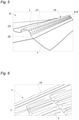
- the invention relates to a flap 1 and a sealing device denoted "D" comprising such a flap 1, said flap 1 being intended to cooperate at least partially with a roof denoted "T".
- the flap 1 comprises in particular a deformable semi-rigid support 3, for example made of aluminum, and more particularly of crepe aluminum.
- the flap 1 also has an adhesion face directed towards the roof T and on which is deposited an adhesion layer 5 consisting of a material configured to adhere to the roof T, for example butyl.
- the adhesion layer 5 can also comprise any other adhesive known to those skilled in the art having similar performance.
- the adhesion layer 5 can cover the adhesion face over at least 50% of the total surface of the adhesion face, and more particularly over at least 90% of the total surface of the membership.
- the adhesion layer 5 completely covers the adhesion face. In this way, the surface of the adhesion layer 5 in contact with the roof T is maximized, which gives better grip of the flap 1 on the roof T.
- the flap 1 comprises a first flap part 7 configured to cooperate at least partially with a rigid body 15 and a second flap part 9 intended to cooperate at least partially with the roof T.
- the adhesion layer 5 is covered at least partially with a permanent passivation layer 11 on the first flap part 7. adhesion 5, and that it therefore cannot be separated from said adhesion layer 5.
- the permanent passivation layer 11 is integral with the adhesion layer 5, and therefore adheres irreversibly to the adhesion layer 5.
- Said permanent passivation layer 11 is configured to be extensible.
- the permanent passivation layer 11 consists of a polymer material, and in particular, without limitation, polyvinylidene chloride, polyvinyl chloride, plasticized polyvinyl chloride, polyethylene with additives or even a polyolefin, making it possible to form a stretchable film up to at least 100% of its initial length without tearing.
- the adhesion layer 5 is also covered at least partially with a temporary protective film 13 mainly on the second part of the flap 9, the temporary protective film 13 being intended to be detached from the adhesion layer 5.
- the temporary protective film 13 can for example cover at least 50% of the adhesion face. It can also be provided that the temporary protective film 13 partially covers the permanent passivation layer 11 along an overlap zone 12. It is therefore clearly understood that the temporary protective film 13 can partially cover the adhesion layer 5 d on the one hand and partially the permanent passivation layer 11 on the other hand. In this way, the temporary protective film 13 adheres to the adhesion layer 5, and can simply be peeled off by gripping the temporary protective film 13 at the level of the covering zone 12 of the permanent passivation layer 11 and of the film of temporary protection 13.
- the sealing device D comprises a rigid body 15, for example made of steel or zinc, comprising fixing elements configured to fix the rigid body 15 and the flap 1.
- the flap 1 can in particular be sewn, and/or glued, and/or stamped, and/or crimped to the rigid body 15.
- the fastening elements may comprise teeth 17 configured to staple the flap 1 and the rigid body 15.
- Each tooth 17 may comprise a fixed end secured to the rigid body 15, and a free end configured to staple the flap 1.
- the free end may have a reduction in section so as to be able to perforate the flap 1.
- the free end may be pointed.
- Fixing openings 19 can be made in the rigid body 15, and configured to allow the free ends of the teeth 17 to pass.
- the fixed end of each tooth 17 is arranged on the side of the flap 1, and each tooth 17 has a curved shape so that the free ends of the teeth 17 are inserted into the fixing openings 19. manner, the teeth 17 can be configured to staple the flap 1 and the rigid body 15 at the level of the first flap part 7.
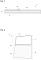
- the sealing device D can be applied to a closure intended to be placed under a line of ridge tiles of a roof.
- the closure may in particular have a symmetrical profile along a median longitudinal axis XX.
- the rigid body 15 comprises a central portion 23 which is preferably planar intended to be capped by the ridge tile. Two sides 25 arranged on either side of the central portion 23 extend laterally and are provided with fastening elements.
- the figure 5 illustrates an embodiment in which the closure comprises a rigid body 15 and two flaps 1 each fixed to the rigid body 15 by each of the panels 25.
- Each panel 25 may comprise a ventilation zone 252 in which are formed ventilation openings 21 configured to ventilate the interior of the line of ridge tiles.
- the rigid body 15 may comprise a plurality of ventilation openings 21 formed in the rigid body 15 so as to provide effective ventilation of the interior of the line of ridge tiles.
- the sections 25 may also include an attachment zone 254 comprising the attachment means.
- Each panel 25 may include the fixing openings 19 provided in the fixing zone 254, and configured to allow the passage of the free ends of the teeth 17.
- the fixed end of each tooth 17 is arranged on the side of the flap 1 , and each tooth 17 has a curved shape so that the free ends of the teeth 17 are inserted into the fixing openings 19 formed between the fixed ends of the teeth 17 and the ventilation zone 252.
- a closure as described above can simply be adapted by those skilled in the art to a sealing device such as a flashing, an edge, a flashing or a photovoltaic panel support frame.
- the sealing device D can be applied to a flashing intended to be placed on a wall overhanging a roof.
- Said flashing comprises a rigid body 15, capable of being fixed to a wall in line with a roof T, integral in a leaktight manner with the flap 1 at the level of the first part of the flap 7.
- the rigid body 15 comprises means for fixing the flap 1 such as teeth configured to clip the flap to the rigid body at the level of the first part of the flap 7 or any other equivalent fastening means previously described, such as a fold or means for fix the flap 1 to the rigid body 15 at the level of the first part of the flap 7 for example.
- said flap 1 is deformable and comprises an outer support layer 3 which is semi-rigid and deformable.
- the outer support layer 3 has an adhesion face directed towards the roof T on which is deposited an inner adhesion layer 5 consisting of a material configured to adhere to the roof T, said adhesion layer 5 of the first part flap 7 being covered at least partially with a permanent passivation layer 11, the permanent passivation layer 11 being configured to be extensible, and said adhesion layer 5 of the second part of the flap 9 intended to cooperate with the roof T being covered at least partially with a temporary protective film 13, this temporary protective film 13 being intended to be necessarily separated from the adhesion layer 5 during implementation on the roof.
- the arrangements previously described make it possible to propose a flap 1 having easy implementation due to the improved adhesion of the second part of flap 9 and the improved extensibility on the first part of flap 7.
- the flap 1 thus allows a connection waterproof roof sections T, and the presence of the adhesion layer 5 prevents the flap 1 to rise when subjected to climatic hazards such as a strong wind.
- the presence of the rigid body 15 makes it possible to guarantee better stability and good resistance over time.
- the deformable semi-rigid support 3 is made of a material making it possible to ensure a smoothing rate of between 20% and 80% and in particular substantially equal to 60%.
- creped aluminum as the constituent material of the deformable semi-rigid support 3 makes it possible to obtain a flap 1 providing a masking rate greater than 60%, while reducing the mass of the flap 1.
Landscapes
- Engineering & Computer Science (AREA)
- Architecture (AREA)
- Civil Engineering (AREA)
- Structural Engineering (AREA)
- Roof Covering Using Slabs Or Stiff Sheets (AREA)
- Building Environments (AREA)
Applications Claiming Priority (1)
| Application Number | Priority Date | Filing Date | Title |
|---|---|---|---|
| FR2007765A FR3112800B1 (fr) | 2020-07-23 | 2020-07-23 | Bavette et dispositif d’étanchéité pour une toiture, et procédé d’assemblage d’un tel dispositif. |
Publications (3)
| Publication Number | Publication Date |
|---|---|
| EP3943684A1 true EP3943684A1 (de) | 2022-01-26 |
| EP3943684B1 EP3943684B1 (de) | 2023-07-19 |
| EP3943684C0 EP3943684C0 (de) | 2023-07-19 |
Family
ID=74183192
Family Applications (1)
| Application Number | Title | Priority Date | Filing Date |
|---|---|---|---|
| EP21187265.0A Active EP3943684B1 (de) | 2020-07-23 | 2021-07-22 | Abweisblech und dichtungsvorrichtung für ein dach und verfahren zur montage einer solchen vorrichtung |
Country Status (2)
| Country | Link |
|---|---|
| EP (1) | EP3943684B1 (de) |
| FR (1) | FR3112800B1 (de) |
Citations (9)
| Publication number | Priority date | Publication date | Assignee | Title |
|---|---|---|---|---|
| US4091135A (en) * | 1972-02-19 | 1978-05-23 | Tajima Roofing Co., Ltd. | Laminated bituminous roofing membrane |
| DE9111300U1 (de) * | 1991-09-11 | 1991-12-05 | Fleck, Oskar, 4354 Datteln | First- oder Gratabdeckungselement |
| DE9216618U1 (de) * | 1992-12-05 | 1993-02-18 | Fleck, Oskar, 4354 Datteln | First- oder Gratabdeckungselement |
| EP1041215A2 (de) * | 1999-03-27 | 2000-10-04 | Oskar Fleck | Plastisch verformbares Abdeckmaterial |
| DE20015297U1 (de) * | 2000-09-04 | 2001-01-11 | Fleck, Oskar, 45711 Datteln | Plastisch verformbares Abdeckmaterial |
| EP1152099A1 (de) * | 2000-05-04 | 2001-11-07 | Verwaltungsgesellschaft Bleiindustrie GmbH & Co. KG vorm. Jung + Lindig | Dichtungsband für eine First- oder Gratabdeckung |
| US6360506B1 (en) * | 1999-06-25 | 2002-03-26 | Icopal Gmbh | Bituminous roofing membrane, and method of joining two roofing membranes |
| CA2549473A1 (en) * | 2003-12-15 | 2005-07-07 | Johns Manville International, Inc. | Self-adhered roofing components, roofing system, and method |
| EP1607214A2 (de) * | 2004-06-15 | 2005-12-21 | Oskar Fleck | Verfahren zur Herstellung eines Abdeckmaterials für Bauzwecke, Vorrichtung dafür und Abdeckmaterial |
-
2020
- 2020-07-23 FR FR2007765A patent/FR3112800B1/fr active Active
-
2021
- 2021-07-22 EP EP21187265.0A patent/EP3943684B1/de active Active
Patent Citations (9)
| Publication number | Priority date | Publication date | Assignee | Title |
|---|---|---|---|---|
| US4091135A (en) * | 1972-02-19 | 1978-05-23 | Tajima Roofing Co., Ltd. | Laminated bituminous roofing membrane |
| DE9111300U1 (de) * | 1991-09-11 | 1991-12-05 | Fleck, Oskar, 4354 Datteln | First- oder Gratabdeckungselement |
| DE9216618U1 (de) * | 1992-12-05 | 1993-02-18 | Fleck, Oskar, 4354 Datteln | First- oder Gratabdeckungselement |
| EP1041215A2 (de) * | 1999-03-27 | 2000-10-04 | Oskar Fleck | Plastisch verformbares Abdeckmaterial |
| US6360506B1 (en) * | 1999-06-25 | 2002-03-26 | Icopal Gmbh | Bituminous roofing membrane, and method of joining two roofing membranes |
| EP1152099A1 (de) * | 2000-05-04 | 2001-11-07 | Verwaltungsgesellschaft Bleiindustrie GmbH & Co. KG vorm. Jung + Lindig | Dichtungsband für eine First- oder Gratabdeckung |
| DE20015297U1 (de) * | 2000-09-04 | 2001-01-11 | Fleck, Oskar, 45711 Datteln | Plastisch verformbares Abdeckmaterial |
| CA2549473A1 (en) * | 2003-12-15 | 2005-07-07 | Johns Manville International, Inc. | Self-adhered roofing components, roofing system, and method |
| EP1607214A2 (de) * | 2004-06-15 | 2005-12-21 | Oskar Fleck | Verfahren zur Herstellung eines Abdeckmaterials für Bauzwecke, Vorrichtung dafür und Abdeckmaterial |
Also Published As
| Publication number | Publication date |
|---|---|
| FR3112800A1 (fr) | 2022-01-28 |
| FR3112800B1 (fr) | 2022-10-28 |
| EP3943684B1 (de) | 2023-07-19 |
| EP3943684C0 (de) | 2023-07-19 |
Similar Documents
| Publication | Publication Date | Title |
|---|---|---|
| EP3074578B1 (de) | Platte, plattenanordnung und zugehörige dachstruktur | |
| FR2924141A1 (fr) | Dispositif support de panneau de couverture de toiture | |
| FR2538434A1 (fr) | Lucarne de couverture avec dispositif d'etancheite | |
| EP3303723B1 (de) | Platte, anordnung der platten und zugehöriges dach | |
| FR2957953A1 (fr) | Dispositif pour supporter des panneaux solaires integres dans une toiture | |
| WO2016189342A1 (fr) | Dispositif de connexion électrique d'installation photovoltaïque | |
| CA3057596A1 (fr) | Vitrage comprenant un cordon profile de clipage pour une piece de couverture clipable | |
| EP3943684B1 (de) | Abweisblech und dichtungsvorrichtung für ein dach und verfahren zur montage einer solchen vorrichtung | |
| EP0399874B1 (de) | Lattenvorrichtung, insbesondere für Überdeckung von geneigten Dächern | |
| EP3712344B1 (de) | Belüfteter firstverschluss für dach | |
| WO2016189343A1 (fr) | Dispositif de connexion électrique d'installation photovoltaïque | |
| AU2009200232A1 (en) | Vented Roof Cover System | |
| EP0427575B1 (de) | Tragendes Profileisen zur Anwendung in Dächern und sein Abdeckungsprofileisen und entlüftende Abdichtungsbauweise aus solchem Profileisen hergestellt | |
| FR2624166A1 (fr) | Dispositifs de ventilation ou aeration et/ou d'eclairage destines a etre places en paroi des batiments | |
| EP0377366B1 (de) | Anschlussschiene für eine ansteigende Dichtung | |
| EP3551816B1 (de) | Dach mit metallischem dachzubehör | |
| FR3065020B1 (fr) | Closoir de bas de pente pour une toiture en tuiles, procede de pose dudit closoir et toiture de batiment le comportant | |
| FR2470216A1 (fr) | Profiles de raccordement du type solin | |
| US10190316B2 (en) | One-piece and two-piece shingle repair patch | |
| EP0851070A1 (de) | Profilträger eines Dichtungsstreifens für eine Wandanschlussverkleidung | |
| EP1219758A1 (de) | Wasserdichte Verbindungsvorrichtung für Verbunddachplatten | |
| FR2843987A1 (fr) | Tuile a facettes | |
| FR2784704A1 (fr) | Dispositif de fixation de toles pour toitures | |
| CH646485A5 (en) | Waterproofing device for a tile roof ridge | |
| FR2714921A1 (fr) | Elément support de tuiles du type canal. |
Legal Events
| Date | Code | Title | Description |
|---|---|---|---|
| PUAI | Public reference made under article 153(3) epc to a published international application that has entered the european phase |
Free format text: ORIGINAL CODE: 0009012 |
|
| STAA | Information on the status of an ep patent application or granted ep patent |
Free format text: STATUS: THE APPLICATION HAS BEEN PUBLISHED |
|
| AK | Designated contracting states |
Kind code of ref document: A1 Designated state(s): AL AT BE BG CH CY CZ DE DK EE ES FI FR GB GR HR HU IE IS IT LI LT LU LV MC MK MT NL NO PL PT RO RS SE SI SK SM TR |
|
| STAA | Information on the status of an ep patent application or granted ep patent |
Free format text: STATUS: REQUEST FOR EXAMINATION WAS MADE |
|
| 17P | Request for examination filed |
Effective date: 20220725 |
|
| RBV | Designated contracting states (corrected) |
Designated state(s): AL AT BE BG CH CY CZ DE DK EE ES FI FR GB GR HR HU IE IS IT LI LT LU LV MC MK MT NL NO PL PT RO RS SE SI SK SM TR |
|
| GRAP | Despatch of communication of intention to grant a patent |
Free format text: ORIGINAL CODE: EPIDOSNIGR1 |
|
| STAA | Information on the status of an ep patent application or granted ep patent |
Free format text: STATUS: GRANT OF PATENT IS INTENDED |
|
| INTG | Intention to grant announced |
Effective date: 20230301 |
|
| GRAS | Grant fee paid |
Free format text: ORIGINAL CODE: EPIDOSNIGR3 |
|
| GRAA | (expected) grant |
Free format text: ORIGINAL CODE: 0009210 |
|
| STAA | Information on the status of an ep patent application or granted ep patent |
Free format text: STATUS: THE PATENT HAS BEEN GRANTED |
|
| AK | Designated contracting states |
Kind code of ref document: B1 Designated state(s): AL AT BE BG CH CY CZ DE DK EE ES FI FR GB GR HR HU IE IS IT LI LT LU LV MC MK MT NL NO PL PT RO RS SE SI SK SM TR |
|
| REG | Reference to a national code |
Ref country code: GB Ref legal event code: FG4D Free format text: NOT ENGLISH |
|
| REG | Reference to a national code |
Ref country code: CH Ref legal event code: EP |
|
| REG | Reference to a national code |
Ref country code: DE Ref legal event code: R096 Ref document number: 602021003555 Country of ref document: DE |
|
| REG | Reference to a national code |
Ref country code: IE Ref legal event code: FG4D Free format text: LANGUAGE OF EP DOCUMENT: FRENCH |
|
| U01 | Request for unitary effect filed |
Effective date: 20230817 |
|
| U07 | Unitary effect registered |
Designated state(s): AT BE BG DE DK EE FI FR IT LT LU LV MT NL PT SE SI Effective date: 20230823 |
|
| U20 | Renewal fee for the european patent with unitary effect paid |
Year of fee payment: 3 Effective date: 20230929 |
|
| REG | Reference to a national code |
Ref country code: LT Ref legal event code: MG9D |
|
| PG25 | Lapsed in a contracting state [announced via postgrant information from national office to epo] |
Ref country code: GR Free format text: LAPSE BECAUSE OF FAILURE TO SUBMIT A TRANSLATION OF THE DESCRIPTION OR TO PAY THE FEE WITHIN THE PRESCRIBED TIME-LIMIT Effective date: 20231020 |
|
| PG25 | Lapsed in a contracting state [announced via postgrant information from national office to epo] |
Ref country code: IS Free format text: LAPSE BECAUSE OF FAILURE TO SUBMIT A TRANSLATION OF THE DESCRIPTION OR TO PAY THE FEE WITHIN THE PRESCRIBED TIME-LIMIT Effective date: 20231119 |
|
| PG25 | Lapsed in a contracting state [announced via postgrant information from national office to epo] |
Ref country code: RS Free format text: LAPSE BECAUSE OF FAILURE TO SUBMIT A TRANSLATION OF THE DESCRIPTION OR TO PAY THE FEE WITHIN THE PRESCRIBED TIME-LIMIT Effective date: 20230719 Ref country code: NO Free format text: LAPSE BECAUSE OF FAILURE TO SUBMIT A TRANSLATION OF THE DESCRIPTION OR TO PAY THE FEE WITHIN THE PRESCRIBED TIME-LIMIT Effective date: 20231019 Ref country code: IS Free format text: LAPSE BECAUSE OF FAILURE TO SUBMIT A TRANSLATION OF THE DESCRIPTION OR TO PAY THE FEE WITHIN THE PRESCRIBED TIME-LIMIT Effective date: 20231119 Ref country code: HR Free format text: LAPSE BECAUSE OF FAILURE TO SUBMIT A TRANSLATION OF THE DESCRIPTION OR TO PAY THE FEE WITHIN THE PRESCRIBED TIME-LIMIT Effective date: 20230719 Ref country code: GR Free format text: LAPSE BECAUSE OF FAILURE TO SUBMIT A TRANSLATION OF THE DESCRIPTION OR TO PAY THE FEE WITHIN THE PRESCRIBED TIME-LIMIT Effective date: 20231020 |
|
| PG25 | Lapsed in a contracting state [announced via postgrant information from national office to epo] |
Ref country code: PL Free format text: LAPSE BECAUSE OF FAILURE TO SUBMIT A TRANSLATION OF THE DESCRIPTION OR TO PAY THE FEE WITHIN THE PRESCRIBED TIME-LIMIT Effective date: 20230719 |
|
| REG | Reference to a national code |
Ref country code: DE Ref legal event code: R097 Ref document number: 602021003555 Country of ref document: DE |
|
| REG | Reference to a national code |
Ref country code: IE Ref legal event code: MM4A |
|
| PG25 | Lapsed in a contracting state [announced via postgrant information from national office to epo] |
Ref country code: ES Free format text: LAPSE BECAUSE OF FAILURE TO SUBMIT A TRANSLATION OF THE DESCRIPTION OR TO PAY THE FEE WITHIN THE PRESCRIBED TIME-LIMIT Effective date: 20230719 |
|
| PG25 | Lapsed in a contracting state [announced via postgrant information from national office to epo] |
Ref country code: SM Free format text: LAPSE BECAUSE OF FAILURE TO SUBMIT A TRANSLATION OF THE DESCRIPTION OR TO PAY THE FEE WITHIN THE PRESCRIBED TIME-LIMIT Effective date: 20230719 Ref country code: RO Free format text: LAPSE BECAUSE OF FAILURE TO SUBMIT A TRANSLATION OF THE DESCRIPTION OR TO PAY THE FEE WITHIN THE PRESCRIBED TIME-LIMIT Effective date: 20230719 Ref country code: ES Free format text: LAPSE BECAUSE OF FAILURE TO SUBMIT A TRANSLATION OF THE DESCRIPTION OR TO PAY THE FEE WITHIN THE PRESCRIBED TIME-LIMIT Effective date: 20230719 Ref country code: CZ Free format text: LAPSE BECAUSE OF FAILURE TO SUBMIT A TRANSLATION OF THE DESCRIPTION OR TO PAY THE FEE WITHIN THE PRESCRIBED TIME-LIMIT Effective date: 20230719 Ref country code: SK Free format text: LAPSE BECAUSE OF FAILURE TO SUBMIT A TRANSLATION OF THE DESCRIPTION OR TO PAY THE FEE WITHIN THE PRESCRIBED TIME-LIMIT Effective date: 20230719 Ref country code: MC Free format text: LAPSE BECAUSE OF FAILURE TO SUBMIT A TRANSLATION OF THE DESCRIPTION OR TO PAY THE FEE WITHIN THE PRESCRIBED TIME-LIMIT Effective date: 20230719 |
|
| PLBE | No opposition filed within time limit |
Free format text: ORIGINAL CODE: 0009261 |
|
| STAA | Information on the status of an ep patent application or granted ep patent |
Free format text: STATUS: NO OPPOSITION FILED WITHIN TIME LIMIT |
|
| 26N | No opposition filed |
Effective date: 20240422 |
|
| U20 | Renewal fee for the european patent with unitary effect paid |
Year of fee payment: 4 Effective date: 20240530 |
|
| PG25 | Lapsed in a contracting state [announced via postgrant information from national office to epo] |
Ref country code: IE Free format text: LAPSE BECAUSE OF NON-PAYMENT OF DUE FEES Effective date: 20230722 |
|
| PG25 | Lapsed in a contracting state [announced via postgrant information from national office to epo] |
Ref country code: IE Free format text: LAPSE BECAUSE OF NON-PAYMENT OF DUE FEES Effective date: 20230722 |
|
| REG | Reference to a national code |
Ref country code: CH Ref legal event code: PL |
|
| PG25 | Lapsed in a contracting state [announced via postgrant information from national office to epo] |
Ref country code: CH Free format text: LAPSE BECAUSE OF NON-PAYMENT OF DUE FEES Effective date: 20240731 |
|
| U20 | Renewal fee for the european patent with unitary effect paid |
Year of fee payment: 5 Effective date: 20250618 |
|
| PG25 | Lapsed in a contracting state [announced via postgrant information from national office to epo] |
Ref country code: CY Free format text: LAPSE BECAUSE OF FAILURE TO SUBMIT A TRANSLATION OF THE DESCRIPTION OR TO PAY THE FEE WITHIN THE PRESCRIBED TIME-LIMIT; INVALID AB INITIO Effective date: 20210722 |
|
| PG25 | Lapsed in a contracting state [announced via postgrant information from national office to epo] |
Ref country code: HU Free format text: LAPSE BECAUSE OF FAILURE TO SUBMIT A TRANSLATION OF THE DESCRIPTION OR TO PAY THE FEE WITHIN THE PRESCRIBED TIME-LIMIT; INVALID AB INITIO Effective date: 20210722 |