EP3943242B1 - Adapter sowie handwerkzeugmaschinensystem mit einer handwerkzeugmaschine und einem adapter - Google Patents
Adapter sowie handwerkzeugmaschinensystem mit einer handwerkzeugmaschine und einem adapter Download PDFInfo
- Publication number
- EP3943242B1 EP3943242B1 EP21179703.0A EP21179703A EP3943242B1 EP 3943242 B1 EP3943242 B1 EP 3943242B1 EP 21179703 A EP21179703 A EP 21179703A EP 3943242 B1 EP3943242 B1 EP 3943242B1
- Authority
- EP
- European Patent Office
- Prior art keywords
- suction
- adapter
- hand
- extraction
- sleeve
- Prior art date
- Legal status (The legal status is an assumption and is not a legal conclusion. Google has not performed a legal analysis and makes no representation as to the accuracy of the status listed.)
- Active
Links
Images



Classifications
-
- B—PERFORMING OPERATIONS; TRANSPORTING
- B24—GRINDING; POLISHING
- B24B—MACHINES, DEVICES, OR PROCESSES FOR GRINDING OR POLISHING; DRESSING OR CONDITIONING OF ABRADING SURFACES; FEEDING OF GRINDING, POLISHING, OR LAPPING AGENTS
- B24B55/00—Safety devices for grinding or polishing machines; Accessories fitted to grinding or polishing machines for keeping tools or parts of the machine in good working condition
- B24B55/06—Dust extraction equipment on grinding or polishing machines
- B24B55/10—Dust extraction equipment on grinding or polishing machines specially designed for portable grinding machines, e.g. hand-guided
-
- B—PERFORMING OPERATIONS; TRANSPORTING
- B24—GRINDING; POLISHING
- B24B—MACHINES, DEVICES, OR PROCESSES FOR GRINDING OR POLISHING; DRESSING OR CONDITIONING OF ABRADING SURFACES; FEEDING OF GRINDING, POLISHING, OR LAPPING AGENTS
- B24B23/00—Portable grinding machines, e.g. hand-guided; Accessories therefor
- B24B23/02—Portable grinding machines, e.g. hand-guided; Accessories therefor with rotating grinding tools; Accessories therefor
- B24B23/028—Angle tools
-
- B—PERFORMING OPERATIONS; TRANSPORTING
- B25—HAND TOOLS; PORTABLE POWER-DRIVEN TOOLS; MANIPULATORS
- B25F—COMBINATION OR MULTI-PURPOSE TOOLS NOT OTHERWISE PROVIDED FOR; DETAILS OR COMPONENTS OF PORTABLE POWER-DRIVEN TOOLS NOT PARTICULARLY RELATED TO THE OPERATIONS PERFORMED AND NOT OTHERWISE PROVIDED FOR
- B25F5/00—Details or components of portable power-driven tools not particularly related to the operations performed and not otherwise provided for
- B25F5/02—Construction of casings, bodies or handles
Definitions
- the present invention relates to an adapter for connecting at least a first or second suction device to a hand-held power tool, wherein the adapter has a suction nozzle that can be attached to the hand-held power tool and a suction sleeve. Furthermore, the present invention relates to a hand-held power tool system with a hand-held power tool and such an adapter.
- An adapter for connecting a suction device to a handheld power tool is known from the prior art.
- the adapter has a suction nozzle for attaching the adapter to a handheld power tool, as well as a suction sleeve for connecting a suction device to the adapter.
- a suction device designed as a dust bag or vacuum cleaner hose can be fixed to the suction sleeve via a rubber sleeve.
- an adapter for connecting a suction device to a handheld power tool is known, to which a vacuum cleaner hose can be fixed via a click connection.
- WO 2016/097106 A1 discloses an adapter according to the preamble of claim 1.
- the present invention relates to an adapter for connecting at least a first or second suction device to a hand-held power tool, wherein the adapter has a suction nozzle that can be attached to the hand-held power tool and a suction sleeve.
- the suction sleeve When the suction sleeve is arranged in If the suction sleeve is arranged in a first predetermined position on the suction nozzle, the first suction device can be connected to the suction nozzle, and if the suction sleeve is arranged in a second predetermined position on the suction nozzle, the second suction device can be connected to the suction sleeve.
- the invention thus makes it possible to provide an adapter in which different suction devices can be connected by means of different arrangements of the suction sleeve on the suction nozzle.
- the suction nozzle has at least one guide track on its outer circumference, wherein the suction sleeve has at least one guide element on its inner circumference for guiding in the at least one guide track of the suction nozzle.
- the at least one guide track is preferably straight, curved and/or spiral-shaped.
- a suitable guideway for moving the suction sleeve relative to the suction nozzle from the first to the second predetermined position, and vice versa can be provided easily and simply.
- the at least one guide track has a first locking receptacle assigned to the first position and a second locking receptacle assigned to the second position, wherein the at least one guide element of the suction sleeve is locked in the first locking receptacle in the first position and is locked in the second locking receptacle in the second position.
- a force fit, a form fit and/or a resilient snap function is formed between the first or second locking receptacle and the at least one guide element in the first and/or second position.
- the suction sleeve has at least one recess for forming a click connection for connection to a suction device in the second position, in particular to a dust bag or a suction hose.
- the suction nozzle has an interface on its inner circumference for connection in the first position to a suction device, in particular to a dust bag or a suction hose.
- the suction nozzle has locking elements for rotatable arrangement on the hand-held power tool.
- the present invention relates to a hand-held power tool system with a hand-held power tool, in particular a hand-held circular saw, and an adapter that can be attached to the hand-held power tool for connecting at least one first or second suction device to the hand-held power tool, wherein the adapter has a suction nozzle that can be attached to the hand-held power tool and a suction sleeve. If the suction sleeve is arranged in a first predetermined position on the suction nozzle, the first suction device can be connected to the suction nozzle, and if the suction sleeve is arranged in a second predetermined position on the suction nozzle, the second suction device can be connected to the suction sleeve.
- the invention thus enables the provision of a hand-held power tool system in which different suction devices can be arranged on the hand-held power tool by arranging the suction sleeve in different positions relative to the suction nozzle of the adapter.
- the adapter can be detachably attached to the hand-held power tool via an associated interface.
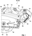
- Fig.1 shows a handheld power tool system 190 with a handheld power tool 100, as well as an adapter 150, which is attached to the handheld power tool 100 for connecting at least one first or second suction device.
- the handheld power tool 100 is designed as a handheld circular saw 100 with a housing 105, which preferably has a handle 102.
- the handheld circular saw 100 is preferably mechanically and electrically connected to a battery pack 115 for mains-independent power supply, but can also be equipped with a power cable in addition to or as an alternative to the mains-dependent power supply.
- the handheld circular saw 100 can alternatively also be designed as a table saw, plunge saw or any other power tool with a saw blade.
- the handheld circular saw 100 is only shown as an example for a hand-held power tool, the use of which generates dust which is preferably to be extracted using a suitable extraction device, and can therefore alternatively be designed as a screwdriver, hand-held milling machine, router, angle grinder, grinding machine, etc.
- the hand-held circular saw 100 is preferably assigned a drive unit 110, which is arranged at least in sections in the housing 105.
- the drive unit 110 can preferably be activated via a hand switch 112.
- the hand switch 112 is preferably arranged on the handle 102 of the housing 105.
- the drive unit 110 is preferably used to drive a tool holder 135 for an exchangeable saw blade 130.
- the drive unit 110 is designed in particular to drive the exchangeable saw blade 130 in rotation about an associated axis of rotation.
- the saw blade 130 is preferably designed as a circular saw blade with an associated cutting edge.
- a protective cover 139 is associated with the saw blade 130.
- the protective cover 139 is preferably mounted in or on the housing 105 so as to be rotatable about the associated axis of rotation or the tool holder 135.
- the protective cover 139 preferably encloses the cutting edge of the saw blade 130 at least in a rest position in which the saw blade 130 is at rest or not rotating.
- the hand-held circular saw 100 preferably has a cover 140 which is designed to cover the saw blade 130 at least in sections.
- the cover 140 is assigned a suction nozzle 145 for connecting the hand-held circular saw 100 to a suction device.
- the adapter 150 according to the invention is preferably detachably arranged on the suction nozzle 145 of the circular saw 100.
- the adapter 150 is preferably designed for the direct connection of different suction devices to the hand-held circular saw 100.
- the adapter 150 is designed for the connection of at least a first or second suction device to the hand-held circular saw 100.
- the adapter 150 is preferably designed for the direct arrangement of a dust bag and/or a suction hose of a dust extraction system via a rubber sleeve.
- the adapter 150 is formed in two parts, wherein the two parts are arranged on one another in a non-detachable manner.
- the adapter 150 has a suction nozzle 160 that can be attached to the hand-held circular saw 100, as well as a suction sleeve 170.
- a suction device e.g. a dust bag or a vacuum cleaner hose
- a suction device can preferably be connected to the inner circumference 204 of the suction nozzle 160 by means of a rubber sleeve on the adapter 150, or alternatively to recesses (320 in Fig.3 ) of the suction sleeve 170 via a click connection, e.g. with a corresponding click & clean adapter of a vacuum cleaner hose.
- the adapter 150 is designed for the connection of different suction devices, but only one of the different suction devices can be arranged on the adapter at a given time.
- Fig. 2 shows the suction nozzle 160 of the adapter 150 of Fig.1 .
- the suction nozzle 160 preferably has a tubular base body with an inner circumference 204 and an outer circumference 202.
- the suction nozzle 160 illustratively has an associated interface 205 for detachably fastening the adapter 150 to the hand-held circular saw 100 of Fig.1
- the suction nozzle 160 has, for example, a section 210 for arranging the suction sleeve 170 of Fig.1
- the first axial end 201, or the interface 205 is arranged at a predetermined angle to the section 210.
- the suction nozzle 160 has at its first axial end 201, or at the interface 205, locking elements 206 for the rotatable arrangement on the hand-held circular saw 100 of Fig.1
- the suction nozzle 160 can be positioned at a desired angle on the circular saw 100 by means of its angled shape. Fig.1 be aligned.
- the suction nozzle 160 On its outer circumference 202, the suction nozzle 160 preferably has at least one guide track 211.
- two guide tracks 211 are provided, which are arranged opposite, in particular diametrically opposite, the Outer circumference 202 are arranged and are preferably point-symmetrical to each other.
- the two guide tracks 211 are preferably formed at the second axial end 203 of the suction nozzle 160.
- the guide tracks 211 are designed to guide the suction sleeve 170 from Fig.1 provided on the suction nozzle 160, as in Fig.4 described.
- the guide tracks 211 are each illustratively designed with a countersunk groove profile or as a recess on the outer circumference 202 of the suction nozzle 160.
- the guide tracks 211 can also be designed in the manner of raised web profiles, in which case correspondingly assigned guide elements (411 in Fig.4 ) of the suction sleeve 170 from Fig.1 must be designed as countersunk guide elements.
- the guide track 211 is designed to move and guide the suction sleeve 170 on the suction nozzle 160.
- at least two defined end positions of the guide track 211 are provided. In addition, more than two end positions can also be formed.
- the guideways 211 are preferably straight, curved and/or spiral-shaped on the outer circumference 202.
- the Fig.2 The guide track 211 shown in its entirety is designed to be straight and preferably has a first and a second locking receptacle 213, 212.
- the locking receptacles 212, 213 preferably form the at least two defined end positions. In these two end positions, the suction sleeve 170 is Fig.1
- the locking receptacles 212, 213 for arranging the suction sleeve 170 are Fig.1 in a first assigned position (510 in Fig.6 ), as well as in a second position (610 in Fig.7 ) on the suction nozzle 160.
- the locking receptacles 212, 213 are preferably arranged perpendicular to the guide track 211.
- the first locking receptacle 213 is assigned a locking element 215 and the second locking receptacle 212 is assigned a locking element 214, wherein the locking elements 214, 215 for the secure arrangement of the suction sleeve 170 of Fig.1 are formed in the associated locking receptacles 212, 213.
- the second locking receptacle 212 is arranged illustratively facing the second axial end 203, and the first locking receptacle 213 is arranged facing the first axial end 201.
- the suction nozzle 160 preferably has functional elements 217, 218 on its outer circumference 202, which are designed to compensate for any play that may exist between the suction nozzle 160 and the suction sleeve 170 of Fig.1 to reduce.
- the functional elements 217, 218 are designed as ribs and/or pins.
- the functional elements 217, 218 are formed on the outer circumference 202 of the suction nozzle 160.
- the functional elements 217, 218 can also be formed on the inner circumference (304 in Fig.3 ) of the suction sleeve 170 from Fig.1
- the functional element 217 is arranged facing the second axial end 203
- the functional element 218 is arranged facing the first axial end 201.
- the suction nozzle 160 preferably has an interface 219 on its inner circumference 204 for connection to an associated suction device.
- This suction device is preferably a dust bag or a suction hose with a connection interface according to a first interface type.
- the interface 219 preferably forms a detachable connection with the suction device, in particular a screw or bayonet connection.
- Fig.3 shows the suction sleeve 170 of the adapter 150 of Fig.1 .
- the suction sleeve 170 preferably has a tubular base body with a first axial end 301 and a second axial end 303.
- a connecting section 311 is provided for connection to the suction nozzle 160 of Fig.1 and Fig.2 and at the second axial end 303, a suction section 312 is illustratively formed for connection to a suction device with a connection interface according to a second interface type.
- a pictogram 332 is provided for illustrating a locking and/or unlocking movement of the suction sleeve 170 on the suction nozzle 160 of Fig.2 provided.
- the suction sleeve 170 preferably has at least one and illustratively two recesses 320 on the suction section 312 for fastening a suction device with a connection interface according to a second interface type.
- the suction sleeve 170 preferably forms a so-called click connection with this suction device
- This suction device is arranged on an inner circumference 304 of the suction sleeve 170 and is preferably also designed as a dust bag or suction hose.
- Fig.4 shows the suction sleeve 170 of Fig.1 and Fig.3 viewed from the first axial end 301.
- the suction sleeve 170 has on its inner circumference 304 in the connecting section 311 at least one guide element 411 for guiding in the at least one guide track 211 of the suction nozzle 160 of Fig. 2 , preferably one guide element per provided guide track.
- two opposing, in particular diametrically opposed, guide elements 411 are preferably arranged on the inner circumference 304 of the suction sleeve 170.
- Each guide element 411 is preferably formed on the inner circumference 304 in the manner of a radially inwardly directed projection.
- the guide elements 411 of the suction sleeve 170 are preferably designed to guide the suction sleeve 170 on the suction nozzle 160.
- the guide elements 411 are designed to align and guide the suction sleeve 170 during a movement from the first end position to a further end position, or from the first locking receptacle 213 to the second locking receptacle 212.
- the guide elements 411 fix the suction sleeve 170 in a respective end position, or the first and/or second locking receptacle 213, 212.
- the guide elements 411 are preferably designed as ribs and/or pin-shaped elevations or bolt-like projections.
- the suction sleeve 170 preferably has a guide recess 415 from its second axial end 303 to the recesses 320.
- the guide recesses 415 are preferably each designed to guide a locking element assigned to a corresponding suction device for forming a click connection with the suction sleeve 170 in the recess 320.
- Fig.5 shows the suction sleeve 170 of Fig.3 and Fig.4 .
- Fig.5 the guide recesses 415, which lead to the recesses 320, starting from the second axial end 303.
- the guide elements 411 are arranged in a predetermined angular position, in particular perpendicular to the recesses 320 on the inner circumference 304 of the suction sleeve 170.
- the recesses 320 and the guide elements 411 can also be arranged at any other angle to one another.
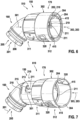
- Fig.6 shows the ready-to-use adapter 150 with the suction nozzle 160 of Fig.1 and Fig.2 , as well as the suction sleeve 170 from Fig.1 and Fig.3 until Fig.5 .
- the suction sleeve 170 with its guide elements 411 is Fig. 4 and Fig. 5 arranged in the guide tracks 211 of the suction nozzle 160.
- the section 210 of the suction nozzle 160 is arranged on the inner circumference 304 of the suction sleeve 170.
- the suction sleeve 170 is arranged, for example, in a first predetermined position 510 on the suction nozzle 160.
- a first suction device can be attached to the suction nozzle 160.
- the first suction device is, as described above, e.g. a dust bag or a suction hose with a connection interface according to a first interface type for connection to the interface 219 of the suction nozzle 160.
- a dust bag and/or a suction hose is arranged via e.g. a rubber sleeve on the inner circumference 204 of the suction nozzle 160, a positive and/or non-positive connection is preferably formed.
- the guide elements 411 of the suction sleeve 170 are in the first locking receptacle 213 of Fig. 2 of the suction nozzle 160.
- the guide elements 411 are arranged in the first locking receptacle 213 of Fig. 2 preferably locked.
- a force fit, a form fit and/or a springy snap function is formed.
- Fig.7 shows the adapter 150 from Fig.6 with the suction nozzle 160 and the suction sleeve 170, wherein the suction sleeve 170 is arranged in a second predetermined position 610 on the suction nozzle 160.
- a second suction device can be fastened to the suction sleeve 170.
- This suction device is preferably a dust bag or a suction hose with a connection interface according to a second interface type, wherein the suction device is preferably connected to the recesses 320 on the suction sleeve 170 via a click connection.
- a click & clean adapter for connecting a suction hose to the inner circumference 304 of the suction sleeve 170, a positive and/or non-positive connection is preferably formed.
- the suction sleeve 170 By moving the suction sleeve 170 relative to the suction nozzle 160 along the guide tracks 211, or from the first locking receptacle 213 into the second locking receptacle 212, the suction sleeve 170 is arranged in the second predetermined position 610.
- the suction sleeve 170 is preferably moved by a combined rotary movement in the circumferential direction of the adapter 150 with a sliding movement along the longitudinal extension of the adapter 150.
- the guide elements 411 of the suction sleeve 170 are in the second locking receptacle 212 in Fig. 2 locked.
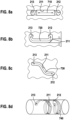
- Fig. 8a shows an exemplary first alternative guideway 211 of the suction nozzle 160 of Fig.1 , Fig. 2 , Fig. 6 and Fig. 7 for the arrangement of the suction sleeve 170 of Fig.1 and Fig.3 until Fig.7 in the first position 510 of Fig.6 and the second position 610 of Fig.7 .
- the guide track 211 is illustratively designed to be straight and has the first and second locking receptacles 213, 212 at its axial ends. By moving it in the axial direction 710, the suction sleeve 170 can be moved from the first locking receptacle 213 to the second locking receptacle 212, or vice versa.
- Fig. 8b shows another alternative embodiment of the guide track 211 of the suction nozzle 160 of Fig.1 , Fig.2 , Fig. 6 and Fig. 7 , which is preferably curved, in particular C-shaped.
- the suction sleeve 170 is displaced along a curved arrow 720.
- the guide track 211 is in the longitudinal direction of the suction nozzle 160 of Fig.1 , Fig. 2 , Fig. 6 and Fig. 7 and the locking receptacles 212, 213 are formed at a predetermined angle, illustratively in the circumferential direction or perpendicular to the guide track 211.
- Fig. 8c shows another alternative embodiment of the guide track 211 of the suction nozzle 160 of Fig.1 , Fig. 2 , Fig. 6 and Fig. 7 , which is at least approximately S-shaped.
- the suction sleeve 170 is moved from the first position 510 of Fig.6 in the second position 610 of Fig.7 , or vice versa, by twisting and simultaneously moving in the longitudinal direction of the suction nozzle 160 along an arrow 730.
- Fig. 8d shows another alternative embodiment of the guide track 211 of the suction nozzle 160 of Fig.1 , Fig.2 , Fig. 6 and Fig. 7 , which is formed spirally in the circumferential direction of the suction nozzle 160.
- the suction sleeve 170 is rotated to move from the first position 510 of Fig.6 in the second position 610 of Fig.7 , or vice versa, along an arrow 740.
- Fig. 9a shows the example of the second locking receptacle 212 of the guide track 211 of the suction nozzle 160 of Fig.1 , Fig.2 , Fig. 6 and Fig. 7 an illustrative arrangement of the guide element 411.
- the locking receptacle 212 is preferably conical and/or tapered. This creates a force or press fit between the locking receptacle 212 and the guide element 411.
- Fig. 9b shows a further embodiment of the locking receptacles 212, 213 of the guide track 211 of the suction nozzle 160 of Fig.1 , Fig. 2 , Fig. 6 and Fig. 7 using the example of the second locking receptacle 212.
- a positive connection is preferably formed between the guide element 411 and the locking receptacle 212.
- the locking receptacle 212 preferably has an application section or a locking lug 820.
- the locking lug 820 preferably applies the guide element 411 arranged in the locking receptacle 212 into the locking receptacle 212 and thus prevents the guide element 411 from moving out of the locking receptacle 212 unintentionally.
- Fig. 9c shows the example of the second locking receptacle 212 of the guide track 211 of the suction nozzle 160 of Fig.1 , Fig.2 , Fig. 6 and Fig. 7 a further embodiment of the locking receptacles 212, 213.
- a positive and non-positive connection is preferably formed between the guide element 411 and the locking receptacle 212.
- the locking receptacle 212 is conical and/or tapered to form a non-positive connection and has at least one and preferably has two opposing locking lugs 820 to form a positive connection.
- Fig.10 shows another exemplary alternative design of the locking receptacles 212, 213 of the guide track 211 of the suction nozzle 160 of Fig.1 , Fig.2 , Fig. 6 and Fig. 7 using the example of the first locking receptacle 213, which forms a resilient snap function with the guide element 411.
- a snap element 910 is preferably assigned to the first locking receptacle 213.
- the snap element 910 is illustratively curved and can be moved at least approximately in the radial direction 911 to accommodate the guide element 411.
- the snap element 910 preferably has an application element 912, which applies the guide element 411 to the locking receptacle 213.
- Fig. 11 shows a further alternative embodiment of the locking receptacles 212, 213 of the guide track 211 of the suction nozzle 160 of Fig.1 , Fig.2 , Fig. 6 and Fig. 7 using the example of the second locking receptacle 212, in which, for example, a resilient snap function is formed between the locking receptacle 212 and the guide element 411.
- the locking receptacle 212 preferably has a locking lug 920.
- the locking lug 920 projects into the guide track 211.
- the guide element 411 is pushed over the locking lug 920 and then into the locking receptacle 212 when it is moved along a longitudinal direction 922 of the guide track 211 in the direction of an arrow 921.
- the locking lug 920 prevents the guide element 411 from being accidentally moved out of the locking receptacle 212, i.e. in a direction opposite to the arrow 922.
Landscapes
- Engineering & Computer Science (AREA)
- Mechanical Engineering (AREA)
- Auxiliary Devices For Machine Tools (AREA)
- Portable Power Tools In General (AREA)
- Manipulator (AREA)
- Endoscopes (AREA)
Description
- Die vorliegende Erfindung betrifft einen Adapter zum Anschluss von zumindest einer ersten oder zweiten Absaugvorrichtung an eine Handwerkzeugmaschine, wobei der Adapter einen an der Handwerkzeugmaschine befestigbaren Absaugstutzen und eine Absaughülse aufweist. Darüber hinaus betrifft die vorliegende Erfindung ein Handwerkzeugmaschinensystem mit einer Handwerkzeugmaschine und einem derartigen Adapter.
- Aus dem Stand der Technik ist ein Adapter zum Anschluss einer Absaugvorrichtung an eine Handwerkzeugmaschine bekannt. Der Adapter weist einen Absaugstutzen zum Befestigen des Adapters an einer Handwerkzeugmaschine auf, sowie eine Absaughülse zum Anschließen einer Absaugvorrichtung an den Adapter. Hierbei kann an der Absaughülse eine als Staubsack oder Staubsaugerschlauch ausgebildete Absaugvorrichtung über eine Gummimuffe fixiert werden. Darüber hinaus ist ein Adapter zum Anschluss einer Absaugvorrichtung an eine Handwerkzeugmaschine bekannt, an dem ein Staubsaugerschlauch über eine Klickverbindung fixiert werden kann.
-
WO 2016/097106 A1 offenbart einen Adapter gemäß dem Oberbegriff von Anspruch 1. - Die vorliegende Erfindung wird im unabhängigen Anspruch 1 definiert. Bevorzugte Ausführungsbeispiele sind in den Unteransprüchen definiert.
- Die vorliegende Erfindung betrifft einen Adapter zum Anschluss von zumindest einer ersten oder zweiten Absaugvorrichtung an eine Handwerkzeugmaschine, wobei der Adapter einen an der Handwerkzeugmaschine befestigbaren Absaugstutzen und eine Absaughülse aufweist. Bei einer Anordnung der Absaughülse in einer ersten vorgegebenen Position am Absaugstutzen ist die erste Absaugvorrichtung am Absaugstutzen anschließbar, und bei einer Anordnung der Absaughülse in einer zweiten vorgegebenen Position am Absaugstutzen ist die zweite Absaugvorrichtung an der Absaughülse anschließbar.
- Die Erfindung ermöglicht somit die Bereitstellung eines Adapters, bei dem durch unterschiedliche Anordnungen der Absaughülse am Absaugstutzen ein Anschluss von unterschiedlichen Absaugvorrichtungen ermöglicht werden kann.
- Erfindungsgemäß weist der Absaugstutzen an seinem Außenumfang zumindest eine Führungsbahn auf, wobei die Absaughülse an ihrem Innenumfang zumindest ein Führungselement zum Führen in der zumindest einen Führungsbahn des Absaugstutzens aufweist.
- Somit kann auf einfache Art und Weise eine Anordnung der Absaughülse relativ zum Absaugstutzen in der ersten oder zweiten vorgegebenen Position zum Anschluss von unterschiedlichen Absaugvorrichtungen ermöglicht werden.
- Die zumindest eine Führungsbahn ist vorzugsweise geradlinig, bogenförmig und/oder spiralförmig ausgebildet.
- Somit kann leicht und unkompliziert eine geeignete Führungsbahn zum Verfahren der Absaughülse relativ zum Absaugstutzen von der ersten in die zweite vorgegebene Position, und umgekehrt, bereitgestellt werden.
- Erfindungsgemäß weist die zumindest eine Führungsbahn eine der ersten Position zugeordnete, erste Rastaufnahme und eine der zweiten Position zugeordnete, zweite Rastaufnahme auf, wobei das zumindest eine Führungselement der Absaughülse in der ersten Position in der ersten Rastaufnahme verrastet ist und in der zweiten Position in der zweiten Rastaufnahme verrastet ist.
- Somit kann eine sichere und zuverlässige Anordnung des Adapters in der ersten oder zweiten vorgegebenen Position ermöglicht werden, wobei eine ungewollte Positionsänderung wirksam verhindert werden kann.
- Vorzugsweise ist zwischen der ersten oder zweiten Rastaufnahme und dem zumindest einen Führungselement in der ersten und/oder zweiten Position ein Kraftschluss, Formschluss und/oder eine federnde Schnappfunktion ausgebildet.
- Somit kann leicht und unkompliziert eine Fixierung einer jeweils eingestellten Position ermöglicht werden.
- Bevorzugt weist die Absaughülse zum Anschluss an eine Absaugvorrichtung in der zweiten Position, insbesondere an einen Staubsack oder einen Absaugschlauch, mindestens eine Ausnehmung zur Ausbildung einer Klickverbindung auf.
- Somit kann auf einfache Art und Weise eine Anordnung einer zweiten Absaugvorrichtung an der Handwerkzeugmaschine über den Adapter ermöglicht werden.
- Vorzugsweise weist der Absaugstutzen an seinem Innenumfang eine Schnittstelle zum Anschluss in der ersten Position an eine Absaugvorrichtung, insbesondere an einen Staubsack oder einen Absaugschlauch, auf.
- Somit kann sicher und zuverlässig eine Anordnung der ersten Absaugvorrichtung an der Handwerkzeugmaschine über den Adapter ermöglicht werden.
- Gemäß einer Ausführungsform weist der Absaugstutzen Rastelemente zur drehbeweglichen Anordnung an der Handwerkzeugmaschine auf.
- Somit kann eine sichere und zuverlässige Anordnung des Adapters an der Handwerkzeugmaschine in einer für einen vorgegebenen Arbeitsvorgang zugeordneten, geeigneten Winkelposition ermöglicht werden.
- Darüber hinaus betrifft die vorliegende Erfindung ein Handwerkzeugmaschinensystem mit einer Handwerkzeugmaschine, insbesondere einer Handkreissäge, und einem an der Handwerkzeugmaschine befestigbaren Adapter zum Anschluss von zumindest einer ersten oder zweiten Absaugvorrichtung an der Handwerkzeugmaschine, wobei der Adapter einen an der Handwerkzeugmaschine befestigbaren Absaugstutzen und eine Absaughülse aufweist. Bei einer Anordnung der Absaughülse in einer ersten vorgegebenen Position am Absaugstutzen ist die erste Absaugvorrichtung am Absaugstutzen anschließbar, und bei einer Anordnung der Absaughülse in einer zweiten vorgegebenen Position am Absaugstutzen ist die zweite Absaugvorrichtung an der Absaughülse anschließbar.
- Die Erfindung ermöglicht somit die Bereitstellung eines Handwerkzeugmaschinensystems, bei dem durch die Anordnung der Absaughülse in unterschiedlichen Positionen relativ zum Absaugstutzen des Adapters unterschiedliche Absaugvorrichtungen an der Handwerkzeugmaschine angeordnet werden können.
- Bevorzugt ist der Adapter über eine zugeordnete Schnittstelle lösbar an der Handwerkzeugmaschine befestigbar.
- Somit kann auf einfache Art und Weise eine Anordnung des Adapters an unterschiedlichen Handwerkzeugmaschinen ermöglicht werden.
- Die Erfindung ist anhand von in den Zeichnungen dargestellten Ausführungsbeispielen in der nachfolgenden Beschreibung näher erläutert. Es zeigen:
- Fig. 1
- eine perspektivische Ansicht eines Handwerkzeugmaschinensystems mit einer Handwerkzeugmaschine und einem Adapter mit einem Absaugstutzen und einer Absaughülse,
- Fig. 2
- eine Seitenansicht des Absaugstutzens des Adapters von
Fig. 1 , - Fig. 3
- eine Seitenansicht der Absaughülse des Adapters von
Fig. 1 , - Fig. 4
- eine perspektivische Vorderansicht der Absaughülse von
Fig. 3 , - Fig. 5
- eine Vorderansicht der Absaughülse von
Fig. 3 undFig. 4 , - Fig. 6
- eine perspektivische Ansicht des Adapters von
Fig. 2 mit der Absaughülse vonFig. 3 undFig. 4 in einer ersten Position relativ zum Absaugstutzen vonFig. 2 , - Fig. 7
- eine perspektivische Ansicht des Adapters von
Fig. 2 undFig. 6 mit der Absaughülse in einer zweiten Position relativ zum Absaugstutzen, - Fig. 8a
- eine Ansicht einer dem Absaugstutzen von
Fig. 2 ,Fig. 6 und Fig. 7 zugeordneten Führungsbahn, - Fig. 8b
- eine Ansicht einer weiteren, dem Absaugstutzen von
Fig. 2 ,Fig. 6 und Fig. 7 zugeordneten Führungsbahn, - Fig. 8c
- eine Ansicht einer alternativen, dem Absaugstutzen von
Fig. 2 ,Fig. 6 und Fig. 7 zugeordneten Führungsbahn, - Fig. 8d
- eine Ansicht einer weiteren, dem Absaugstutzen von
Fig. 2 ,Fig. 6 und Fig. 7 zugeordneten Führungsbahn, - Fig. 9a
- eine Ansicht einer der Führungsbahn von
Fig. 8a bis Fig. 8d des Absaugstutzens vonFig. 2 ,Fig. 6 und Fig. 7 zugeordneten Rastaufnahme, - Fig. 9b
- eine Ansicht einer weiteren, der Führungsbahn von
Fig. 8a bis Fig. 8d des Absaugstutzens vonFig. 2 ,Fig. 6 und Fig. 7 zugeordneten Rastaufnahme, - Fig. 9c
- eine Ansicht einer alternativen, der Führungsbahn von
Fig. 8a bis Fig. 8d des Absaugstutzens vonFig. 2 ,Fig. 6 und Fig. 7 zugeordneten Rastaufnahme, - Fig. 10
- eine Ansicht eines weiteren, der Absaughülse von
Fig. 2 ,Fig. 4 bis Fig. 7 zugeordneten Führungselements, und - Fig. 11
- eine Ansicht eines alternativen, der Absaughülse von
Fig. 2 ,Fig. 4 bis Fig. 7 zugeordneten Führungselements. - In den Figuren werden Elemente mit gleicher oder vergleichbarer Funktion mit identischen Bezugszeichen versehen und nur einmal genauer beschrieben.
-
Fig. 1 zeigt ein Handwerkzeugmaschinensystem 190 mit einer Handwerkzeugmaschine 100, sowie einem illustrativ an der Handwerkzeugmaschine 100 befestigten Adapter 150 zum Anschluss von zumindest einer ersten oder zweiten Absaugvorrichtung. Die Handwerkzeugmaschine 100 ist beispielhaft als Handkreissäge 100 mit einem Gehäuse 105 ausgebildet, das bevorzugt einen Handgriff 102 aufweist. Bevorzugt ist die Handkreissäge 100 zur netzunabhängigen Stromversorgung mechanisch und elektrisch mit einem Akkupack 115 verbunden, kann jedoch auch zusätzlich oder alternativ zur netzabhängigen Stromversorgung mit einem Netzkabel ausgerüstet sein. Die Handkreissäge 100 kann alternativ auch als Tischkreissäge, Tauchsäge oder ein beliebig anderes Elektrowerkzeug mit einem Sägeblatt ausgebildet sein. Darüber hinaus ist die Handkreissäge 100 lediglich beispielhaft für eine Handwerkzeugmaschine gezeigt, bei deren Anwendung Staub entsteht, der vorzugsweise über eine geeignete Absaugvorrichtung abzusaugen ist, und kann somit alternativ z.B. auch als Schrauber, Handfräsmaschine, Oberfräser, Winkelschleifer, Schleifmaschine usw. ausgebildet sein. - Der Handkreissäge 100 ist vorzugsweise eine Antriebseinheit 110 zugeordnet, die zumindest abschnittsweise im Gehäuse 105 angeordnet ist. Die Antriebseinheit 110 ist vorzugsweise über einen Handschalter 112 aktivierbar. Bevorzugt ist der Handschalter 112 am Handgriff 102 des Gehäuses 105 angeordnet. Bevorzugt dient die Antriebseinheit 110 zum Antrieb einer Werkzeugaufnahme 135 für ein austauschbares Sägeblatt 130. Dabei ist die Antriebseinheit 110 insbesondere zum drehenden Antrieb des austauschbaren Sägeblatts 130 um eine zugeordnete Drehachse ausgebildet. Das Sägeblatt 130 ist vorzugsweise als Kreissägeblatt mit einer zugeordneten Schneide ausgebildet.
- Bevorzugt ist dem Sägeblatt 130 eine Schutzabdeckung 139 zugeordnet. Die Schutzabdeckung 139 ist vorzugsweise um die zugeordnete Drehachse bzw. die Werkzeugaufnahme 135 drehbar im bzw. am Gehäuse 105 gelagert. Dabei umschließt die Schutzabdeckung 139 bevorzugt die Schneide des Sägeblatts 130 zumindest in einer Ruheposition, in der das Sägeblatt 130 ruht bzw. nicht rotiert.
- Des Weiteren weist die Handkreissäge 100 vorzugsweise eine Abdeckhaube 140 auf, die dazu ausgebildet ist, das Sägeblatt 130 zumindest abschnittsweise abzudecken. Gemäß einer Ausführungsform ist der Abdeckhaube 140 ein Absaugstutzen 145 zum Verbinden der Handkreissäge 100 mit einer Absaugvorrichtung zugeordnet. In
Fig. 1 ist an dem Absaugstutzen 145 der Handkreissäge 100 der erfindungsgemäße Adapter 150 bevorzugt lösbar angeordnet. - Der Adapter 150 ist vorzugsweise zum direkten Anschluss von unterschiedlichen Absaugvorrichtungen an die Handkreissäge 100 ausgebildet. Insbesondere ist der Adapter 150 zum Anschluss von zumindest einer ersten oder zweiten Absaugvorrichtung an der Handkreissäge 100 ausgebildet. Vorzugsweise ist der Adapter 150 zum direkten Anordnen eines Staubsack und/oder eines Absaugschlauchs einer Staubabsaugung über eine Gummimuffe ausgebildet.
- Bevorzugt ist der Adapter 150 zweiteilig ausgebildet, wobei die entsprechenden beiden Teile nicht lösbar aneinander angeordnet sind. Illustrativ weist der Adapter 150 einen an der Handkreissäge 100 befestigbaren Absaugstutzen 160, sowie eine Absaughülse 170 auf.
- Vorzugsweise können zumindest zwei, bevorzugt drei unterschiedliche Absaugvorrichtungen am Adapter angeordnet werden. Hierbei kann bevorzugt eine Absaugvorrichtung, z.B. ein Staubsack oder ein Staubsaugerschlauch, am Innenumfang 204 des Absaugstutzens 160 mittels einer Gummimuffe am Adapter 150 angeschlossen werden, oder alternativ an Ausnehmungen (320 in
Fig. 3 ) der Absaughülse 170 über eine Klickverbindung, z.B. mit einem entsprechenden Klick & Clean-Adapter eines Staubsaugerschlauchs. Es wird darauf hingewiesen, dass der Adapter 150 zum Anschluss von unterschiedlichen Absaugvorrichtungen ausgebildet ist, jedoch zu einem vorgegebenen Zeitpunkt immer nur jeweils eine der unterschiedlichen Absaugvorrichtungen am Adapter angeordnet werden kann. -
Fig. 2 zeigt den Absaugstutzen 160 des Adapters 150 vonFig. 1 . Der Absaugstutzen 160 weist bevorzugt einen rohrförmigen Grundkörper auf, mit einem Innenumfang 204 sowie einem Außenumfang 202. An seinem ersten axialen Ende 201 weist der Absaugstutzen 160 illustrativ eine zugeordnete Schnittstelle 205 zur lösbaren Befestigung des Adapters 150 an der Handkreissäge 100 vonFig. 1 auf. An seinem zweiten axialen Ende 203 weist der Absaugstutzen 160 beispielhaft einen Abschnitt 210 zur Anordnung der Absaughülse 170 vonFig. 1 auf. Illustrativ ist das erste axiale Ende 201, bzw. die Schnittstelle 205, in einem vorgegebenen Winkel zum Abschnitt 210 angeordnet. - Bevorzugt weist der Absaugstutzen 160 an seinem ersten axialen Ende 201, bzw. an der Schnittstelle 205, Rastelemente 206 zur drehbeweglichen Anordnung an der Handkreissäge 100 von
Fig. 1 auf. Hierbei kann der Absaugstutzen 160 durch seine abgewinkelte Form in einer gewünschten Winkelposition an der Handkreissäge 100 vonFig. 1 ausgerichtet werden. - An seinem Außenumfang 202 weist der Absaugstutzen 160 vorzugsweise zumindest eine Führungsbahn 211 auf. Illustrativ sind zwei Führungsbahnen 211 vorgesehen, die gegenüberliegend, insbesondere diametral gegenüberliegend, am Außenumfang 202 angeordnet sind und bevorzugt punktsymmetrisch zueinander ausgebildet sind. Die zwei Führungsbahnen 211 sind bevorzugt am zweiten axialen Ende 203 des Absaugstutzens 160 ausgebildet. Dabei sind die Führungsbahnen 211 zum Führen der Absaughülse 170 von
Fig. 1 am Absaugstutzen 160 vorgesehen, wie beiFig. 4 beschrieben. - Die Führungsbahnen 211 sind illustrativ jeweils mit einem versenkten Nutprofil, bzw. als Ausnehmung, am Außenumfang 202 des Absaugstutzens 160 ausgebildet. Jedoch können die Führungsbahnen 211 jeweils auch nach Art von erhobenen Stegprofilen ausgebildet sein, wobei in diesem Fall entsprechend zugeordnete Führungselemente (411 in
Fig. 4 ) der Absaughülse 170 vonFig. 1 als versenkte Führungselemente ausgebildet sein müssen. Die Führungsbahn 211 ist zum Bewegen und Führen der Absaughülse 170 am Absaugstutzen 160 ausgebildet. Bevorzugt sind zumindest zwei definierte Endpositionen der Führungsbahn 211 vorgesehen. Darüber hinaus können auch mehr als zwei Endpositionen ausgebildet sein. - Die Führungsbahnen 211 sind vorzugsweise geradlinig, bogenförmig und/oder spiralförmig am Außenumfang 202 ausgebildet. Illustrativ ist die in
Fig. 2 komplett gezeigte Führungsbahn 211 geradlinig ausgebildet und weist bevorzugt eine erste und eine zweite Rastaufnahme 213, 212 auf. Bevorzugt bilden die Rastaufnahmen 212, 213 die zumindest zwei definierten Endpositionen aus. In diesen beiden Endpositionen wird die Absaughülse 170 vonFig. 1 fixiert. Hierbei sind die Rastaufnahmen 212, 213 zur Anordnung der Absaughülse 170 vonFig. 1 in einer ersten zugeordneten Position (510 inFig. 6 ), sowie in einer zweiten Position (610 inFig. 7 ) am Absaugstutzen 160 ausgebildet. Die Rastaufnahmen 212, 213 sind dabei vorzugsweise senkrecht zur Führungsbahn 211 angeordnet. Bevorzugt ist der ersten Rastaufnahme 213 ein Rastelement 215 zugeordnet und der zweiten Rastaufnahme 212 ist ein Rastelement 214 zugeordnet, wobei die Rastelemente 214, 215 zur sicheren Anordnung der Absaughülse 170 vonFig. 1 in den zugeordneten Rastaufnahmen 212, 213 ausgebildet sind. Darüber hinaus ist illustrativ die zweite Rastaufnahme 212 dem zweiten axialen Ende 203 zugewandt angeordnet, und die erste Rastaufnahme 213 ist dem ersten axialen Ende 201 zugewandt angeordnet. - Des Weiteren weist der Absaugstutzen 160 an seinem Außenumfang 202 vorzugsweise Funktionselemente 217, 218 auf, die dazu ausgebildet sind, ein ggf. vorhandenes Spiel zwischen dem Absaugstutzen 160 und der Absaughülse 170 von
Fig. 1 zur reduzieren. Gemäß einer Ausführungsform sind die Funktionselemente 217, 218 als Rippen und/oder Stifte ausgebildet. Illustrativ sind die Funktionselemente 217, 218 am Außenumfang 202 des Absaugstutzens 160 ausgebildet. Jedoch können die Funktionselemente 217, 218 auch am Innenumfang (304 inFig. 3 ) der Absaughülse 170 vonFig. 1 angeordnet sein. Illustrativ ist das Funktionselement 217 dem zweiten axialen Ende 203 zugewandt angeordnet, und das Funktionselement 218 ist dem ersten axialen Ende 201 zugewandt angeordnet. - Darüber hinaus weist der Absaugstutzen 160 bevorzugt an seinem Innenumfang 204 eine Schnittstelle 219 zum Anschluss an eine zugeordnete Absaugvorrichtung auf. Diese Absaugvorrichtung ist vorzugsweise ein Staubsack oder ein Absaugschlauch mit einer Verbindungsschnittstelle gemäß eines ersten Schnittstellentyps. Bevorzugt bildet die Schnittstelle 219 mit der Absaugvorrichtung eine lösbare Verbindung, insbesondere eine Schraub- oder Bajonettverbindung, aus.
-
Fig. 3 zeigt die Absaughülse 170 des Adapters 150 vonFig. 1 . Die Absaughülse 170 weist bevorzugt einen rohrförmigen Grundkörper mit einem ersten axialen Ende 301 und einem zweiten axialen Ende 303 auf. Am ersten axialen Ende 301 ist beispielhaft ein Verbindungsabschnitt 311 zur Verbindung mit dem Absaugstutzen 160 vonFig. 1 undFig. 2 ausgebildet und am zweiten axialen Ende 303 ist illustrativ ein Absaugabschnitt 312 zur Verbindung mit einer Absaugvorrichtung mit einer Verbindungsschnittstelle gemäß eines zweiten Schnittstellentyps ausgebildet. - Am Außenumfang 302 der Absaughülse 170, vorzugsweise am Verbindungsabschnitt 311, ist beispielhaft ein Piktogramm 332 zur Verdeutlichung einer Verriegelungs- und/oder Entriegelungsbewegung der Absaughülse 170 am Absaugstutzen 160 von
Fig. 2 vorgesehen. Darüber hinaus weist die Absaughülse 170 am Absaugabschnitt 312 bevorzugt zumindest eine und illustrativ zwei Ausnehmungen 320 zur Befestigung einer Absaugvorrichtung mit einer Verbindungsschnittstelle gemäß eines zweiten Schnittstellentyps auf. Bevorzugt bildet die Absaughülse 170 mit dieser Absaugvorrichtung eine sogenannte Klickverbindung aus. Diese Absaugvorrichtung wird dabei an einem Innenumfang 304 der Absaughülse 170 angeordnet und ist vorzugsweise ebenfalls als Staubsack oder Absaugschlauch ausgebildet. -
Fig. 4 zeigt die Absaughülse 170 vonFig. 1 undFig. 3 vom ersten axialen Ende 301 aus betrachtet. Die Absaughülse 170 weist an ihrem Innenumfang 304 im Verbindungsabschnitt 311 zumindest ein Führungselement 411 zum Führen in der zumindest einen Führungsbahn 211 des Absaugstutzens 160 vonFig. 2 auf, bevorzugt jeweils ein Führungselement pro vorgesehener Führungsbahn. Dementsprechend sind bevorzugt zwei gegenüberliegende, insbesondere diametral gegenüberliegende, Führungselemente 411 am Innenumfang 304 der Absaughülse 170 angeordnet. Jedes Führungselement 411 ist vorzugsweise am Innenumfang 304 nach Art eines radial einwärts gerichteten Vorsprungs ausgebildet. - Die Führungselemente 411 der Absaughülse 170 sind vorzugsweise zum Führen der Absaughülse 170 am Absaugstutzen 160 ausgebildet. Insbesondere sind die Führungselemente 411 zur Ausrichtung und Führung der Absaughülse 170 bei einer Bewegung von der ersten Endposition in eine weitere Endposition, bzw. von der ersten Rastaufnahme 213 zur zweiten Rastaufnahme 212, ausgebildet. Darüber hinaus fixieren die Führungselemente 411 die Absaughülse 170 in einer jeweiligen Endposition, bzw. der ersten und/oder zweiten Rastaufnahme 213, 212. Bevorzugt sind die Führungselemente 411 als Rippen und/oder stiftförmige Erhebungen bzw. bolzenartige Vorsprünge ausgebildet.
- Des Weiteren weist die Absaughülse 170 von ihrem zweiten axialen Ende 303 ausgehend hin zu den Ausnehmungen 320 bevorzugt jeweils eine Führungsausnehmung 415 auf. Die Führungsausnehmungen 415 sind vorzugsweise jeweils zum Führen eines einer entsprechenden Absaugvorrichtung zur Ausbildung einer Klickverbindung mit der Absaughülse 170 zugeordneten Rastelements in der Ausnehmung 320 ausgebildet.
-
Fig. 5 zeigt die Absaughülse 170 vonFig. 3 undFig. 4 . Dabei verdeutlichtFig. 5 die zwei vorzugsweise einander gegenüberliegenden Führungselemente 411, die stegartig nach radial innen am Innenumfang 304 der Absaughülse 170 ausgebildet sind. Des Weiteren verdeutlichtFig. 5 die Führungsausnehmungen 415, die zu den Ausnehmungen 320, ausgehend vom zweiten axialen Ende 303, führen. - Bevorzugt sind die Führungselemente 411 in einer vorgegebenen Winkelposition, insbesondere senkrecht zu den Ausnehmungen 320 am Innenumfang 304 der Absaughülse 170, angeordnet. Jedoch können die Ausnehmungen 320 und die Führungselemente 411 auch in einem beliebig anderen Winkel zueinander angeordnet sein.
-
Fig. 6 zeigt den betriebsbereit montierten Adapter 150 mit dem Absaugstutzen 160 vonFig. 1 undFig. 2 , sowie der Absaughülse 170 vonFig. 1 undFig. 3 bisFig. 5 . Die Absaughülse 170 ist mit ihren Führungselementen 411 vonFig. 4 und Fig. 5 in den Führungsbahnen 211 des Absaugstutzens 160 angeordnet. Hierbei ist der Abschnitt 210 des Absaugstutzens 160 am Innenumfang 304 der Absaughülse 170 angeordnet. - In
Fig. 6 ist die Absaughülse 170 beispielhaft in einer ersten vorgegebenen Position 510 am Absaugstutzen 160 angeordnet. In dieser ersten vorgegebenen Position 510 ist eine erste Absaugvorrichtung am Absaugstutzen 160 befestigbar. Die erste Absaugvorrichtung ist dabei, wie oben beschrieben, z.B. ein Staubsack oder ein Absaugschlauch mit einer Verbindungsschnittstelle gemäß eines ersten Schnittstellentyps zur Verbindung mit der Schnittstelle 219 des Absaugstutzens 160. Bei einer Anordnung eines Staubsacks und/oder eines Absaugschlauches über z.B. eine Gummimuffe am Innenumfang 204 des Absaugstutzens 160 wird vorzugsweise ein Form- und/oder Kraftschluss ausgebildet. - In der ersten vorgegebenen Position 510 sind die Führungselemente 411 der Absaughülse 170 in der ersten Rastaufnahme 213 von
Fig. 2 des Absaugstutzens 160 angeordnet. Insbesondere sind die Führungselemente 411 in der ersten Rastaufnahme 213 vonFig. 2 vorzugsweise verrastet. Dabei wird zwischen den Führungselementen 411 und den Rastaufnahmen 212, 213 vonFig. 2 bevorzugt ein Kraftschluss, Formschluss und/oder eine federnde Schnappfunktion ausgebildet. -
Fig. 7 zeigt den Adapter 150 vonFig. 6 mit dem Absaugstutzen 160 und der Absaughülse 170, wobei die Absaughülse 170 in einer zweiten vorgegebenen Position 610 am Absaugstutzen 160 angeordnet ist. In dieser zweiten vorgegebenen Position 610 ist eine zweite Absaugvorrichtung an der Absaughülse 170 befestigbar. Diese Absaugvorrichtung ist bevorzugt ein Staubsack oder ein Absaugschlauch mit einer Verbindungsschnittstelle gemäß eines zweiten Schnittstellentyps, wobei die Absaugvorrichtung vorzugsweise über eine Klickverbindung mit den Ausnehmungen 320 an der Absaughülse 170 verbunden ist. Bei einer Anordnung z.B. eines Klick & Clean-Adapters zum Anschluss eines Absaugschlauches am Innenumfang 304 der Absaughülse 170 wird vorzugsweise ein Form- und/oder Kraftschluss ausgebildet. - Durch ein Verschieben der Absaughülse 170 relativ zum Absaugstutzen 160 entlang den Führungsbahnen 211, bzw. von der ersten Rastaufnahme 213 in die zweite Rastaufnahme 212, wird die Absaughülse 170 in der zweiten vorgegebenen Position 610 angeordnet. Dabei erfolgt bevorzugt ein Verschieben der Absaughülse 170 durch eine kombinierte Drehbewegung in Umfangsrichtung des Adapters 150 mit einer Schiebebewegung entlang der Längserstreckung des Adapters 150. In der zweiten vorgegebenen Position 610 sind die Führungselemente 411 der Absaughülse 170 in der zweiten Rastaufnahme 212 in
Fig. 2 verrastet. -
Fig. 8a zeigt eine beispielhafte erste alternative Führungsbahn 211 des Absaugstutzens 160 vonFig. 1 ,Fig. 2 ,Fig. 6 und Fig. 7 zur Anordnung der Absaughülse 170 vonFig. 1 undFig. 3 bisFig. 7 in der ersten Position 510 vonFig. 6 sowie der zweiten Position 610 vonFig. 7 . Die Führungsbahn 211 ist dabei illustrativ geradlinig ausgebildet und weist an ihren axialen Enden die erste und zweite Rastaufnahme 213, 212 auf. Durch ein Verschieben in axialer Richtung 710 kann die Absaughülse 170 von der ersten Rastaufnahme 213 zur zweiten Rastaufnahme 212, oder umgekehrt, verschoben werden. -
Fig. 8b zeigt eine weitere alternative Ausführungsform der Führungsbahn 211 des Absaugstutzens 160 vonFig. 1 ,Fig. 2 ,Fig. 6 und Fig. 7 , die vorzugsweise bogenförmig, insbesondere C-förmig, ausgebildet ist. Dabei erfolgt ein Verschieben der Absaughülse 170 entlang eines bogenförmigen Pfeils 720. Bevorzugt ist die Führungsbahn 211 in Längsrichtung des Absaugstutzens 160 vonFig. 1 ,Fig. 2 ,Fig. 6 und Fig. 7 ausgebildet und die Rastaufnahmen 212, 213 sind in einem vorgegebenen Winkel, illustrativ in Umfangsrichtung bzw. senkrecht zur Führungsbahn 211, ausgebildet. -
Fig. 8c zeigt eine weitere alternative Ausführungsform der Führungsbahn 211 des Absaugstutzens 160 vonFig. 1 ,Fig. 2 ,Fig. 6 und Fig. 7 , die zumindest annähernd S-förmig ausgebildet ist. Dabei erfolgt ein Bewegen der Absaughülse 170 von der ersten Position 510 vonFig. 6 in die zweite Position 610 vonFig. 7 , oder umgekehrt, durch ein Verdrehen und gleichzeitiges Verschieben in Längsrichtung des Absaugstutzens 160 entlang eines Pfeils 730. -
Fig. 8d zeigt eine weitere alternative Ausführungsform der Führungsbahn 211 des Absaugstutzens 160 vonFig. 1 ,Fig. 2 ,Fig. 6 und Fig. 7 , die spiralförmig in Umfangsrichtung des Absaugstutzens 160 ausgebildet ist. Dabei erfolgt ein Verdrehen der Absaughülse 170 zur Bewegung von der ersten Position 510 vonFig. 6 in die zweite Position 610 vonFig. 7 , oder umgekehrt, entlang eines Pfeils 740. -
Fig. 9a zeigt am Beispiel der zweiten Rastaufnahme 212 der Führungsbahn 211 des Absaugstutzens 160 vonFig. 1 ,Fig. 2 ,Fig. 6 und Fig. 7 eine illustrative Anordnung des Führungselements 411. Die Rastaufnahme 212 ist vorzugsweise konus- und/oder kegelförmig ausgebildet. Hierdurch erfolgt zwischen der Rastaufnahme 212 und dem Führungselement 411 ein Kraft- bzw. Pressschluss. -
Fig. 9b zeigt eine weitere Ausgestaltung der Rastaufnahmen 212, 213 der Führungsbahn 211 des Absaugstutzens 160 vonFig. 1 ,Fig. 2 ,Fig. 6 und Fig. 7 am Beispiel der zweiten Rastaufnahme 212. Dabei wird zwischen dem Führungselement 411 und der Rastaufnahme 212 bevorzugt ein Formschluss ausgebildet. Zur Ausbildung des Formschlusses weist die Rastaufnahme 212 vorzugsweise einen Beaufschlagungsabschnitt bzw. eine Rastnase 820 auf. Die Rastnase 820 beaufschlagt vorzugsweise das in der Rastaufnahme 212 angeordnete Führungselement 411 in die Rastaufnahme 212 und verhindert somit ein ungewolltes Herausbewegen des Führungselements 411 aus der Rastaufnahme 212 heraus. -
Fig. 9c zeigt am Beispiel der zweiten Rastaufnahme 212 der Führungsbahn 211 des Absaugstutzens 160 vonFig. 1 ,Fig. 2 ,Fig. 6 und Fig. 7 eine weitere Ausführungsform der Rastaufnahmen 212, 213. Dabei wird zwischen dem Führungselement 411 und der Rastaufnahme 212 bevorzugt ein Form- und Kraftschluss ausgebildet. Vorzugsweise ist die Rastaufnahme 212 konus- und/oder kegelförmig zur Ausbildung eines Kraftschlusses ausgebildet und weist zumindest eine und bevorzugt zwei gegenüberliegende Rastnasen 820 zur Ausbildung eines Formschlusses auf. -
Fig. 10 zeigt eine weitere beispielhafte alternative Ausbildung der Rastaufnahmen 212, 213 der Führungsbahn 211 des Absaugstutzens 160 vonFig. 1 ,Fig. 2 ,Fig. 6 und Fig. 7 am Beispiel der ersten Rastaufnahme 213, die mit dem Führungselement 411 eine federnde Schnappfunktion ausbildet. Der ersten Rastaufnahme 213 ist dabei bevorzugt ein Schnappelement 910 zugeordnet. Das Schnappelement 910 ist illustrativ bogenförmig ausgebildet und zumindest annähernd in radialer Richtung 911 zur Aufnahme des Führungselements 411 bewegbar. Das Schnappelement 910 weist vorzugsweise ein Beaufschlagungselement 912 auf, das das Führungselement 411 in die Rastaufnahme 213 beaufschlagt. -
Fig. 11 zeigt eine weitere alternative Ausführungsform der Rastaufnahmen 212, 213 der Führungsbahn 211 des Absaugstutzens 160 vonFig. 1 ,Fig. 2 ,Fig. 6 und Fig. 7 am Beispiel der zweiten Rastaufnahme 212, bei der beispielhaft eine federnde Schnappfunktion zwischen der Rastaufnahme 212 und dem Führungselement 411 ausgebildet wird. Hierbei weist die Rastaufnahme 212 bevorzugt eine Rastnase 920 auf. Die Rastnase 920 ragt in die Führungsbahn 211 hinein. Das Führungselement 411 wird bei einem Verschieben entlang einer Längsrichtung 922 der Führungsbahn 211 in Richtung eines Pfeils 921 über die Rastnase 920 hinweg und dann in die Rastaufnahme 212 hinein beaufschlagt. Darüber hinaus verhindert die Rastnase 920 bei einer Anordnung des Führungselements 411 in der Rastaufnahme 212 ein ungewolltes Verschieben des Führungselements 411 aus der Rastaufnahme 212 heraus, d.h. in einer zum Pfeil 922 entgegengesetzten Richtung.
Claims (8)
- Adapter (150) zum Anschluss von zumindest einer ersten oder zweiten Absaugvorrichtung an eine Handwerkzeugmaschine (100), wobei der Adapter (150) einen an der Handwerkzeugmaschine (100) befestigbaren Absaugstutzen (160) und eine Absaughülse (170) aufweist, wobei bei einer Anordnung der Absaughülse (170) in einer ersten vorgegebenen Position (510) am Absaugstutzen (160) die erste Absaugvorrichtung am Absaugstutzen (160) anschließbar ist, und bei einer Anordnung der Absaughülse (170) in einer zweiten vorgegebenen Position (610) am Absaugstutzen (160) die zweite Absaugvorrichtung an der Absaughülse (170) anschließbar ist, wobei der Absaugstutzen (160) an seinem Außenumfang (202) zumindest eine Führungsbahn (211) aufweist, wobei die Absaughülse (170) an ihrem Innenumfang (304) zumindest ein Führungselement (411) zum Führen in der zumindest einen Führungsbahn (211) des Absaugstutzens (160) aufweist, dadurch gekennzeichnet, dass die zumindest eine Führungsbahn (211) eine der ersten Position (510) zugeordnete, erste Rastaufnahme (213) und eine der zweiten Position (610) zugeordnete, zweite Rastaufnahme (212) aufweist, wobei das zumindest eine Führungselement (411) der Absaughülse (170) in der ersten Position (510) in der ersten Rastaufnahme (212) verrastet ist und in der zweiten Position (610) in der zweiten Rastaufnahme (212) verrastet ist.
- Adapter nach Anspruch 1, dadurch gekennzeichnet, dass die zumindest eine Führungsbahn (211) geradlinig, bogenförmig und/oder spiralförmig ausgebildet ist.
- Adapter nach Anspruch 1, dadurch gekennzeichnet, dass zwischen der ersten oder zweiten Rastaufnahme (213, 212) und dem zumindest einen Führungselement (411) in der ersten und/oder zweiten Position (510, 610) ein Kraftschluss, Formschluss und/oder eine federnde Schnappfunktion ausgebildet ist.
- Adapter nach einem der vorhergehenden Ansprüche, dadurch gekennzeichnet, dass die Absaughülse (170) zum Anschluss an eine Absaugvorrichtung in der zweiten Position (610), insbesondere an einen Staubsack oder einen Absaugschlauch, mindestens eine Ausnehmung (320) zur Ausbildung einer Klickverbindung aufweist.
- Adapter nach einem der vorhergehenden Ansprüche, dadurch gekennzeichnet, dass der Absaugstutzen (160) an seinem Innenumfang (204) eine Schnittstelle (219) zum Anschluss in der ersten Position (510) an eine Absaugvorrichtung, insbesondere an einen Staubsack oder einen Absaugschlauch, aufweist.
- Adapter nach einem der vorhergehenden Ansprüche, dadurch gekennzeichnet, dass der Absaugstutzen (160) Rastelemente (206) zur drehbeweglichen Anordnung an der Handwerkzeugmaschine (100) aufweist.
- Handwerkzeugmaschinensystem (190) mit einer Handwerkzeugmaschine (100), insbesondere einer Handkreissäge, und einem an der Handwerkzeugmaschine (100) befestigbaren Adapter (150) nach einem der Ansprüche 1 bis 6.
- Handwerkzeugmaschinensystem nach Anspruch 7, dadurch gekennzeichnet, dass der Adapter (150) über eine zugeordnete Schnittstelle (205) lösbar an der Handwerkzeugmaschine (100) befestigbar ist.
Applications Claiming Priority (1)
| Application Number | Priority Date | Filing Date | Title |
|---|---|---|---|
| DE102020208343.6A DE102020208343A1 (de) | 2020-07-03 | 2020-07-03 | Adapter sowie Handwerkzeugmaschinensystem mit einer Handwerkzeugmaschine und einem Adapter |
Publications (3)
| Publication Number | Publication Date |
|---|---|
| EP3943242A2 EP3943242A2 (de) | 2022-01-26 |
| EP3943242A3 EP3943242A3 (de) | 2022-04-27 |
| EP3943242B1 true EP3943242B1 (de) | 2024-08-28 |
Family
ID=76483195
Family Applications (1)
| Application Number | Title | Priority Date | Filing Date |
|---|---|---|---|
| EP21179703.0A Active EP3943242B1 (de) | 2020-07-03 | 2021-06-16 | Adapter sowie handwerkzeugmaschinensystem mit einer handwerkzeugmaschine und einem adapter |
Country Status (2)
| Country | Link |
|---|---|
| EP (1) | EP3943242B1 (de) |
| DE (1) | DE102020208343A1 (de) |
Family Cites Families (7)
| Publication number | Priority date | Publication date | Assignee | Title |
|---|---|---|---|---|
| US7168127B2 (en) * | 2005-02-10 | 2007-01-30 | Nationwide Sales & Service, Inc. | Vacuum cleaner handle assemblies and adapters mating therewith |
| DE102012020546B4 (de) | 2012-10-19 | 2025-11-13 | Festool Gmbh | Saugschlauch mit einem Schlauchanschlussstück und Staubsauger mit einem Saugschlauch |
| DE102014001349A1 (de) * | 2014-02-01 | 2015-08-06 | Festool Gmbh | Anschlussvorrichtung für eine Staubabfuhreinrichtung und eine Hand-Werkzeugmaschine |
| DE102014119249A1 (de) * | 2014-12-19 | 2016-06-23 | Festool Gmbh | Saugschlauch-Anschlussstück |
| US20160327195A1 (en) | 2015-05-04 | 2016-11-10 | James William Johnson | Quick connect system for vent hose hook-up |
| EP3178614A1 (de) | 2015-12-11 | 2017-06-14 | HILTI Aktiengesellschaft | Anschlussvorrichtung |
| DE102018102855A1 (de) * | 2017-08-11 | 2019-02-14 | Festool Gmbh | Hand-Werkzeugmaschine mit einem Absauganschluss |
-
2020
- 2020-07-03 DE DE102020208343.6A patent/DE102020208343A1/de active Pending
-
2021
- 2021-06-16 EP EP21179703.0A patent/EP3943242B1/de active Active
Also Published As
| Publication number | Publication date |
|---|---|
| EP3943242A2 (de) | 2022-01-26 |
| EP3943242A3 (de) | 2022-04-27 |
| DE102020208343A1 (de) | 2022-01-05 |
Similar Documents
| Publication | Publication Date | Title |
|---|---|---|
| EP3261805B1 (de) | Handwerkzeugmaschine | |
| EP0836544B1 (de) | Elektrische handschleifmaschine | |
| EP0142611B1 (de) | Bohrwerkzeug zur Herstellung von Hinterschneidungen in vorgefertigten Bohrungen | |
| DE102014224591B4 (de) | Werkzeugvorsatz sowie Werkzeugsystem | |
| EP0561246A1 (de) | Handwerkzeugmaschine mit Werkzeughalter | |
| CH616355A5 (de) | ||
| EP0407337A1 (de) | Handgerät mit Trenn- oder Schleifscheibe | |
| EP0545142A1 (de) | Handfräse | |
| WO2012007203A1 (de) | Werkzeughalterung für eine werkzeugmaschine | |
| EP1618990B1 (de) | Handwerkzeugmaschine, insbesondere Winkelschleifer | |
| EP3517249B1 (de) | Haltevorrichtung für eine handwerkzeugmaschine | |
| DE102015209017B4 (de) | Zwischenvorsatz für eine Handwerkzeugmaschine | |
| EP2497589A1 (de) | Kalibrier- und Anfaswerkzeug für rohrförmige Werkstücke | |
| DE10332918A1 (de) | Fadenschneider | |
| EP3943242A2 (de) | Adapter sowie handwerkzeugmaschinensystem mit einer handwerkzeugmaschine und einem adapter | |
| EP0842012B1 (de) | Schwingschleifer | |
| EP1326727B1 (de) | Rotierendes werkzeug | |
| DE102013220202B4 (de) | Absaugvorrichtung für eine Werkzeugmaschine | |
| DE19952039A1 (de) | Spitzer | |
| DE1006311B (de) | Spitzmaschine mit einem aus zwei gegeneinander verdrehbaren Teilen gebildeten Spitzergehaeuse | |
| DE2937885C2 (de) | Zahnärztliches Handstück | |
| EP1627611B1 (de) | Medizinischer Handstückkopf zur Übertragung einer Hubbewegung auf ein Werkzeug | |
| DE4019727A1 (de) | Mit der antriebsspindel einer handgefuehrten elektrowerkzeugmaschine kuppelbares schnellwechselfutter | |
| DE102020000368B3 (de) | Spitzer für Bleistifte mit einem Querschnitt der in orthogonalen Raumrichtungen unterschiedliche Abmessungen aufweist | |
| EP0920950B1 (de) | Manuell handhabbares Bearbeitungsgerät |
Legal Events
| Date | Code | Title | Description |
|---|---|---|---|
| PUAI | Public reference made under article 153(3) epc to a published international application that has entered the european phase |
Free format text: ORIGINAL CODE: 0009012 |
|
| STAA | Information on the status of an ep patent application or granted ep patent |
Free format text: STATUS: THE APPLICATION HAS BEEN PUBLISHED |
|
| AK | Designated contracting states |
Kind code of ref document: A2 Designated state(s): AL AT BE BG CH CY CZ DE DK EE ES FI FR GB GR HR HU IE IS IT LI LT LU LV MC MK MT NL NO PL PT RO RS SE SI SK SM TR |
|
| PUAL | Search report despatched |
Free format text: ORIGINAL CODE: 0009013 |
|
| AK | Designated contracting states |
Kind code of ref document: A3 Designated state(s): AL AT BE BG CH CY CZ DE DK EE ES FI FR GB GR HR HU IE IS IT LI LT LU LV MC MK MT NL NO PL PT RO RS SE SI SK SM TR |
|
| RIC1 | Information provided on ipc code assigned before grant |
Ipc: B25F 5/02 20060101ALI20220324BHEP Ipc: B24B 23/02 20060101ALI20220324BHEP Ipc: B24B 55/10 20060101AFI20220324BHEP |
|
| STAA | Information on the status of an ep patent application or granted ep patent |
Free format text: STATUS: REQUEST FOR EXAMINATION WAS MADE |
|
| 17P | Request for examination filed |
Effective date: 20221027 |
|
| RBV | Designated contracting states (corrected) |
Designated state(s): AL AT BE BG CH CY CZ DE DK EE ES FI FR GB GR HR HU IE IS IT LI LT LU LV MC MK MT NL NO PL PT RO RS SE SI SK SM TR |
|
| GRAP | Despatch of communication of intention to grant a patent |
Free format text: ORIGINAL CODE: EPIDOSNIGR1 |
|
| STAA | Information on the status of an ep patent application or granted ep patent |
Free format text: STATUS: GRANT OF PATENT IS INTENDED |
|
| INTG | Intention to grant announced |
Effective date: 20240613 |
|
| GRAS | Grant fee paid |
Free format text: ORIGINAL CODE: EPIDOSNIGR3 |
|
| GRAA | (expected) grant |
Free format text: ORIGINAL CODE: 0009210 |
|
| STAA | Information on the status of an ep patent application or granted ep patent |
Free format text: STATUS: THE PATENT HAS BEEN GRANTED |
|
| AK | Designated contracting states |
Kind code of ref document: B1 Designated state(s): AL AT BE BG CH CY CZ DE DK EE ES FI FR GB GR HR HU IE IS IT LI LT LU LV MC MK MT NL NO PL PT RO RS SE SI SK SM TR |
|
| REG | Reference to a national code |
Ref country code: CH Ref legal event code: EP |
|
| REG | Reference to a national code |
Ref country code: DE Ref legal event code: R096 Ref document number: 502021004919 Country of ref document: DE |
|
| REG | Reference to a national code |
Ref country code: IE Ref legal event code: FG4D Free format text: LANGUAGE OF EP DOCUMENT: GERMAN |
|
| REG | Reference to a national code |
Ref country code: LT Ref legal event code: MG9D |
|
| PG25 | Lapsed in a contracting state [announced via postgrant information from national office to epo] |
Ref country code: NO Free format text: LAPSE BECAUSE OF FAILURE TO SUBMIT A TRANSLATION OF THE DESCRIPTION OR TO PAY THE FEE WITHIN THE PRESCRIBED TIME-LIMIT Effective date: 20241128 |
|
| PG25 | Lapsed in a contracting state [announced via postgrant information from national office to epo] |
Ref country code: NL Free format text: LAPSE BECAUSE OF FAILURE TO SUBMIT A TRANSLATION OF THE DESCRIPTION OR TO PAY THE FEE WITHIN THE PRESCRIBED TIME-LIMIT Effective date: 20240828 Ref country code: PT Free format text: LAPSE BECAUSE OF FAILURE TO SUBMIT A TRANSLATION OF THE DESCRIPTION OR TO PAY THE FEE WITHIN THE PRESCRIBED TIME-LIMIT Effective date: 20241230 Ref country code: GR Free format text: LAPSE BECAUSE OF FAILURE TO SUBMIT A TRANSLATION OF THE DESCRIPTION OR TO PAY THE FEE WITHIN THE PRESCRIBED TIME-LIMIT Effective date: 20241129 Ref country code: PL Free format text: LAPSE BECAUSE OF FAILURE TO SUBMIT A TRANSLATION OF THE DESCRIPTION OR TO PAY THE FEE WITHIN THE PRESCRIBED TIME-LIMIT Effective date: 20240828 Ref country code: FI Free format text: LAPSE BECAUSE OF FAILURE TO SUBMIT A TRANSLATION OF THE DESCRIPTION OR TO PAY THE FEE WITHIN THE PRESCRIBED TIME-LIMIT Effective date: 20240828 |
|
| PG25 | Lapsed in a contracting state [announced via postgrant information from national office to epo] |
Ref country code: BG Free format text: LAPSE BECAUSE OF FAILURE TO SUBMIT A TRANSLATION OF THE DESCRIPTION OR TO PAY THE FEE WITHIN THE PRESCRIBED TIME-LIMIT Effective date: 20240828 |
|
| PG25 | Lapsed in a contracting state [announced via postgrant information from national office to epo] |
Ref country code: LV Free format text: LAPSE BECAUSE OF FAILURE TO SUBMIT A TRANSLATION OF THE DESCRIPTION OR TO PAY THE FEE WITHIN THE PRESCRIBED TIME-LIMIT Effective date: 20240828 |
|
| REG | Reference to a national code |
Ref country code: NL Ref legal event code: MP Effective date: 20240828 |
|
| PG25 | Lapsed in a contracting state [announced via postgrant information from national office to epo] |
Ref country code: IS Free format text: LAPSE BECAUSE OF FAILURE TO SUBMIT A TRANSLATION OF THE DESCRIPTION OR TO PAY THE FEE WITHIN THE PRESCRIBED TIME-LIMIT Effective date: 20241228 |
|
| PG25 | Lapsed in a contracting state [announced via postgrant information from national office to epo] |
Ref country code: HR Free format text: LAPSE BECAUSE OF FAILURE TO SUBMIT A TRANSLATION OF THE DESCRIPTION OR TO PAY THE FEE WITHIN THE PRESCRIBED TIME-LIMIT Effective date: 20240828 |
|
| PG25 | Lapsed in a contracting state [announced via postgrant information from national office to epo] |
Ref country code: RS Free format text: LAPSE BECAUSE OF FAILURE TO SUBMIT A TRANSLATION OF THE DESCRIPTION OR TO PAY THE FEE WITHIN THE PRESCRIBED TIME-LIMIT Effective date: 20241128 Ref country code: ES Free format text: LAPSE BECAUSE OF FAILURE TO SUBMIT A TRANSLATION OF THE DESCRIPTION OR TO PAY THE FEE WITHIN THE PRESCRIBED TIME-LIMIT Effective date: 20240828 |
|
| PG25 | Lapsed in a contracting state [announced via postgrant information from national office to epo] |
Ref country code: RS Free format text: LAPSE BECAUSE OF FAILURE TO SUBMIT A TRANSLATION OF THE DESCRIPTION OR TO PAY THE FEE WITHIN THE PRESCRIBED TIME-LIMIT Effective date: 20241128 Ref country code: PT Free format text: LAPSE BECAUSE OF FAILURE TO SUBMIT A TRANSLATION OF THE DESCRIPTION OR TO PAY THE FEE WITHIN THE PRESCRIBED TIME-LIMIT Effective date: 20241230 Ref country code: PL Free format text: LAPSE BECAUSE OF FAILURE TO SUBMIT A TRANSLATION OF THE DESCRIPTION OR TO PAY THE FEE WITHIN THE PRESCRIBED TIME-LIMIT Effective date: 20240828 Ref country code: NO Free format text: LAPSE BECAUSE OF FAILURE TO SUBMIT A TRANSLATION OF THE DESCRIPTION OR TO PAY THE FEE WITHIN THE PRESCRIBED TIME-LIMIT Effective date: 20241128 Ref country code: NL Free format text: LAPSE BECAUSE OF FAILURE TO SUBMIT A TRANSLATION OF THE DESCRIPTION OR TO PAY THE FEE WITHIN THE PRESCRIBED TIME-LIMIT Effective date: 20240828 Ref country code: LV Free format text: LAPSE BECAUSE OF FAILURE TO SUBMIT A TRANSLATION OF THE DESCRIPTION OR TO PAY THE FEE WITHIN THE PRESCRIBED TIME-LIMIT Effective date: 20240828 Ref country code: IS Free format text: LAPSE BECAUSE OF FAILURE TO SUBMIT A TRANSLATION OF THE DESCRIPTION OR TO PAY THE FEE WITHIN THE PRESCRIBED TIME-LIMIT Effective date: 20241228 Ref country code: HR Free format text: LAPSE BECAUSE OF FAILURE TO SUBMIT A TRANSLATION OF THE DESCRIPTION OR TO PAY THE FEE WITHIN THE PRESCRIBED TIME-LIMIT Effective date: 20240828 Ref country code: GR Free format text: LAPSE BECAUSE OF FAILURE TO SUBMIT A TRANSLATION OF THE DESCRIPTION OR TO PAY THE FEE WITHIN THE PRESCRIBED TIME-LIMIT Effective date: 20241129 Ref country code: FI Free format text: LAPSE BECAUSE OF FAILURE TO SUBMIT A TRANSLATION OF THE DESCRIPTION OR TO PAY THE FEE WITHIN THE PRESCRIBED TIME-LIMIT Effective date: 20240828 Ref country code: ES Free format text: LAPSE BECAUSE OF FAILURE TO SUBMIT A TRANSLATION OF THE DESCRIPTION OR TO PAY THE FEE WITHIN THE PRESCRIBED TIME-LIMIT Effective date: 20240828 Ref country code: BG Free format text: LAPSE BECAUSE OF FAILURE TO SUBMIT A TRANSLATION OF THE DESCRIPTION OR TO PAY THE FEE WITHIN THE PRESCRIBED TIME-LIMIT Effective date: 20240828 |
|
| PG25 | Lapsed in a contracting state [announced via postgrant information from national office to epo] |
Ref country code: DK Free format text: LAPSE BECAUSE OF FAILURE TO SUBMIT A TRANSLATION OF THE DESCRIPTION OR TO PAY THE FEE WITHIN THE PRESCRIBED TIME-LIMIT Effective date: 20240828 Ref country code: RO Free format text: LAPSE BECAUSE OF FAILURE TO SUBMIT A TRANSLATION OF THE DESCRIPTION OR TO PAY THE FEE WITHIN THE PRESCRIBED TIME-LIMIT Effective date: 20240828 Ref country code: SM Free format text: LAPSE BECAUSE OF FAILURE TO SUBMIT A TRANSLATION OF THE DESCRIPTION OR TO PAY THE FEE WITHIN THE PRESCRIBED TIME-LIMIT Effective date: 20240828 |
|
| PG25 | Lapsed in a contracting state [announced via postgrant information from national office to epo] |
Ref country code: EE Free format text: LAPSE BECAUSE OF FAILURE TO SUBMIT A TRANSLATION OF THE DESCRIPTION OR TO PAY THE FEE WITHIN THE PRESCRIBED TIME-LIMIT Effective date: 20240828 |
|
| PG25 | Lapsed in a contracting state [announced via postgrant information from national office to epo] |
Ref country code: CZ Free format text: LAPSE BECAUSE OF FAILURE TO SUBMIT A TRANSLATION OF THE DESCRIPTION OR TO PAY THE FEE WITHIN THE PRESCRIBED TIME-LIMIT Effective date: 20240828 |
|
| PG25 | Lapsed in a contracting state [announced via postgrant information from national office to epo] |
Ref country code: SK Free format text: LAPSE BECAUSE OF FAILURE TO SUBMIT A TRANSLATION OF THE DESCRIPTION OR TO PAY THE FEE WITHIN THE PRESCRIBED TIME-LIMIT Effective date: 20240828 Ref country code: IT Free format text: LAPSE BECAUSE OF FAILURE TO SUBMIT A TRANSLATION OF THE DESCRIPTION OR TO PAY THE FEE WITHIN THE PRESCRIBED TIME-LIMIT Effective date: 20240828 |
|
| REG | Reference to a national code |
Ref country code: DE Ref legal event code: R097 Ref document number: 502021004919 Country of ref document: DE |
|
| PLBE | No opposition filed within time limit |
Free format text: ORIGINAL CODE: 0009261 |
|
| STAA | Information on the status of an ep patent application or granted ep patent |
Free format text: STATUS: NO OPPOSITION FILED WITHIN TIME LIMIT |
|
| PGFP | Annual fee paid to national office [announced via postgrant information from national office to epo] |
Ref country code: GB Payment date: 20250620 Year of fee payment: 5 |
|
| PGFP | Annual fee paid to national office [announced via postgrant information from national office to epo] |
Ref country code: FR Payment date: 20250626 Year of fee payment: 5 |
|
| PGFP | Annual fee paid to national office [announced via postgrant information from national office to epo] |
Ref country code: AT Payment date: 20250721 Year of fee payment: 5 |
|
| 26N | No opposition filed |
Effective date: 20250530 |
|
| PG25 | Lapsed in a contracting state [announced via postgrant information from national office to epo] |
Ref country code: SE Free format text: LAPSE BECAUSE OF FAILURE TO SUBMIT A TRANSLATION OF THE DESCRIPTION OR TO PAY THE FEE WITHIN THE PRESCRIBED TIME-LIMIT Effective date: 20240828 |
|
| PGFP | Annual fee paid to national office [announced via postgrant information from national office to epo] |
Ref country code: DE Payment date: 20250814 Year of fee payment: 5 |
|
| REG | Reference to a national code |
Ref country code: CH Ref legal event code: H13 Free format text: ST27 STATUS EVENT CODE: U-0-0-H10-H13 (AS PROVIDED BY THE NATIONAL OFFICE) Effective date: 20260127 |
|
| PG25 | Lapsed in a contracting state [announced via postgrant information from national office to epo] |
Ref country code: MC Free format text: LAPSE BECAUSE OF FAILURE TO SUBMIT A TRANSLATION OF THE DESCRIPTION OR TO PAY THE FEE WITHIN THE PRESCRIBED TIME-LIMIT Effective date: 20240828 |
|
| PG25 | Lapsed in a contracting state [announced via postgrant information from national office to epo] |
Ref country code: LU Free format text: LAPSE BECAUSE OF NON-PAYMENT OF DUE FEES Effective date: 20250616 |
|
| REG | Reference to a national code |
Ref country code: BE Ref legal event code: MM Effective date: 20250630 |
|
| PG25 | Lapsed in a contracting state [announced via postgrant information from national office to epo] |
Ref country code: IE Free format text: LAPSE BECAUSE OF NON-PAYMENT OF DUE FEES Effective date: 20250616 |
|
| PG25 | Lapsed in a contracting state [announced via postgrant information from national office to epo] |
Ref country code: BE Free format text: LAPSE BECAUSE OF NON-PAYMENT OF DUE FEES Effective date: 20250630 |
|
| PG25 | Lapsed in a contracting state [announced via postgrant information from national office to epo] |
Ref country code: CH Free format text: LAPSE BECAUSE OF NON-PAYMENT OF DUE FEES Effective date: 20250630 |