EP3942994B1 - Lichtquellenvorrichtung - Google Patents
Lichtquellenvorrichtung Download PDFInfo
- Publication number
- EP3942994B1 EP3942994B1 EP20904264.7A EP20904264A EP3942994B1 EP 3942994 B1 EP3942994 B1 EP 3942994B1 EP 20904264 A EP20904264 A EP 20904264A EP 3942994 B1 EP3942994 B1 EP 3942994B1
- Authority
- EP
- European Patent Office
- Prior art keywords
- light
- light source
- light beam
- fresnel lenses
- led
- Prior art date
- Legal status (The legal status is an assumption and is not a legal conclusion. Google has not performed a legal analysis and makes no representation as to the accuracy of the status listed.)
- Active
Links
Images



Classifications
-
- G—PHYSICS
- G02—OPTICS
- G02B—OPTICAL ELEMENTS, SYSTEMS OR APPARATUS
- G02B23/00—Telescopes, e.g. binoculars; Periscopes; Instruments for viewing the inside of hollow bodies; Viewfinders; Optical aiming or sighting devices
- G02B23/24—Instruments or systems for viewing the inside of hollow bodies, e.g. fibrescopes
- G02B23/2407—Optical details
- G02B23/2461—Illumination
- G02B23/2469—Illumination using optical fibres
-
- A—HUMAN NECESSITIES
- A61—MEDICAL OR VETERINARY SCIENCE; HYGIENE
- A61B—DIAGNOSIS; SURGERY; IDENTIFICATION
- A61B1/00—Instruments for performing medical examinations of the interior of cavities or tubes of the body by visual or photographical inspection, e.g. endoscopes; Illuminating arrangements therefor
- A61B1/06—Instruments for performing medical examinations of the interior of cavities or tubes of the body by visual or photographical inspection, e.g. endoscopes; Illuminating arrangements therefor with illuminating arrangements
- A61B1/0661—Endoscope light sources
-
- A—HUMAN NECESSITIES
- A61—MEDICAL OR VETERINARY SCIENCE; HYGIENE
- A61B—DIAGNOSIS; SURGERY; IDENTIFICATION
- A61B1/00—Instruments for performing medical examinations of the interior of cavities or tubes of the body by visual or photographical inspection, e.g. endoscopes; Illuminating arrangements therefor
- A61B1/06—Instruments for performing medical examinations of the interior of cavities or tubes of the body by visual or photographical inspection, e.g. endoscopes; Illuminating arrangements therefor with illuminating arrangements
- A61B1/0661—Endoscope light sources
- A61B1/0684—Endoscope light sources using light emitting diodes [LED]
-
- A—HUMAN NECESSITIES
- A61—MEDICAL OR VETERINARY SCIENCE; HYGIENE
- A61B—DIAGNOSIS; SURGERY; IDENTIFICATION
- A61B1/00—Instruments for performing medical examinations of the interior of cavities or tubes of the body by visual or photographical inspection, e.g. endoscopes; Illuminating arrangements therefor
- A61B1/00002—Operational features of endoscopes
- A61B1/00043—Operational features of endoscopes provided with output arrangements
- A61B1/00045—Display arrangement
-
- A—HUMAN NECESSITIES
- A61—MEDICAL OR VETERINARY SCIENCE; HYGIENE
- A61B—DIAGNOSIS; SURGERY; IDENTIFICATION
- A61B1/00—Instruments for performing medical examinations of the interior of cavities or tubes of the body by visual or photographical inspection, e.g. endoscopes; Illuminating arrangements therefor
- A61B1/00163—Optical arrangements
- A61B1/00188—Optical arrangements with focusing or zooming features
-
- A—HUMAN NECESSITIES
- A61—MEDICAL OR VETERINARY SCIENCE; HYGIENE
- A61B—DIAGNOSIS; SURGERY; IDENTIFICATION
- A61B1/00—Instruments for performing medical examinations of the interior of cavities or tubes of the body by visual or photographical inspection, e.g. endoscopes; Illuminating arrangements therefor
- A61B1/00163—Optical arrangements
- A61B1/00188—Optical arrangements with focusing or zooming features
- A61B1/0019—Optical arrangements with focusing or zooming features characterised by variable lenses
-
- A—HUMAN NECESSITIES
- A61—MEDICAL OR VETERINARY SCIENCE; HYGIENE
- A61B—DIAGNOSIS; SURGERY; IDENTIFICATION
- A61B1/00—Instruments for performing medical examinations of the interior of cavities or tubes of the body by visual or photographical inspection, e.g. endoscopes; Illuminating arrangements therefor
- A61B1/04—Instruments for performing medical examinations of the interior of cavities or tubes of the body by visual or photographical inspection, e.g. endoscopes; Illuminating arrangements therefor combined with photographic or television appliances
-
- A—HUMAN NECESSITIES
- A61—MEDICAL OR VETERINARY SCIENCE; HYGIENE
- A61B—DIAGNOSIS; SURGERY; IDENTIFICATION
- A61B1/00—Instruments for performing medical examinations of the interior of cavities or tubes of the body by visual or photographical inspection, e.g. endoscopes; Illuminating arrangements therefor
- A61B1/04—Instruments for performing medical examinations of the interior of cavities or tubes of the body by visual or photographical inspection, e.g. endoscopes; Illuminating arrangements therefor combined with photographic or television appliances
- A61B1/043—Instruments for performing medical examinations of the interior of cavities or tubes of the body by visual or photographical inspection, e.g. endoscopes; Illuminating arrangements therefor combined with photographic or television appliances for fluorescence imaging
-
- A—HUMAN NECESSITIES
- A61—MEDICAL OR VETERINARY SCIENCE; HYGIENE
- A61B—DIAGNOSIS; SURGERY; IDENTIFICATION
- A61B1/00—Instruments for performing medical examinations of the interior of cavities or tubes of the body by visual or photographical inspection, e.g. endoscopes; Illuminating arrangements therefor
- A61B1/06—Instruments for performing medical examinations of the interior of cavities or tubes of the body by visual or photographical inspection, e.g. endoscopes; Illuminating arrangements therefor with illuminating arrangements
- A61B1/0638—Instruments for performing medical examinations of the interior of cavities or tubes of the body by visual or photographical inspection, e.g. endoscopes; Illuminating arrangements therefor with illuminating arrangements providing two or more wavelengths
-
- A—HUMAN NECESSITIES
- A61—MEDICAL OR VETERINARY SCIENCE; HYGIENE
- A61B—DIAGNOSIS; SURGERY; IDENTIFICATION
- A61B1/00—Instruments for performing medical examinations of the interior of cavities or tubes of the body by visual or photographical inspection, e.g. endoscopes; Illuminating arrangements therefor
- A61B1/06—Instruments for performing medical examinations of the interior of cavities or tubes of the body by visual or photographical inspection, e.g. endoscopes; Illuminating arrangements therefor with illuminating arrangements
- A61B1/07—Instruments for performing medical examinations of the interior of cavities or tubes of the body by visual or photographical inspection, e.g. endoscopes; Illuminating arrangements therefor with illuminating arrangements using light-conductive means, e.g. optical fibres
-
- A—HUMAN NECESSITIES
- A61—MEDICAL OR VETERINARY SCIENCE; HYGIENE
- A61B—DIAGNOSIS; SURGERY; IDENTIFICATION
- A61B90/00—Instruments, implements or accessories specially adapted for surgery or diagnosis and not covered by any of the groups A61B1/00 - A61B50/00, e.g. for luxation treatment or for protecting wound edges
- A61B90/30—Devices for illuminating a surgical field, the devices having an interrelation with other surgical devices or with a surgical procedure
-
- A—HUMAN NECESSITIES
- A61—MEDICAL OR VETERINARY SCIENCE; HYGIENE
- A61B—DIAGNOSIS; SURGERY; IDENTIFICATION
- A61B90/00—Instruments, implements or accessories specially adapted for surgery or diagnosis and not covered by any of the groups A61B1/00 - A61B50/00, e.g. for luxation treatment or for protecting wound edges
- A61B90/39—Markers, e.g. radio-opaque or breast lesions markers
-
- A—HUMAN NECESSITIES
- A61—MEDICAL OR VETERINARY SCIENCE; HYGIENE
- A61N—ELECTROTHERAPY; MAGNETOTHERAPY; RADIATION THERAPY; ULTRASOUND THERAPY
- A61N5/00—Radiation therapy
- A61N5/06—Radiation therapy using light
- A61N5/0613—Apparatus adapted for a specific treatment
- A61N5/062—Photodynamic therapy, i.e. excitation of an agent
-
- A—HUMAN NECESSITIES
- A61—MEDICAL OR VETERINARY SCIENCE; HYGIENE
- A61N—ELECTROTHERAPY; MAGNETOTHERAPY; RADIATION THERAPY; ULTRASOUND THERAPY
- A61N5/00—Radiation therapy
- A61N5/06—Radiation therapy using light
- A61N5/067—Radiation therapy using light using laser light
-
- F—MECHANICAL ENGINEERING; LIGHTING; HEATING; WEAPONS; BLASTING
- F21—LIGHTING
- F21V—FUNCTIONAL FEATURES OR DETAILS OF LIGHTING DEVICES OR SYSTEMS THEREOF; STRUCTURAL COMBINATIONS OF LIGHTING DEVICES WITH OTHER ARTICLES, NOT OTHERWISE PROVIDED FOR
- F21V5/00—Refractors for light sources
- F21V5/04—Refractors for light sources of lens shape
- F21V5/045—Refractors for light sources of lens shape the lens having discontinuous faces, e.g. Fresnel lenses
-
- G—PHYSICS
- G02—OPTICS
- G02B—OPTICAL ELEMENTS, SYSTEMS OR APPARATUS
- G02B19/00—Condensers, e.g. light collectors or similar non-imaging optics
- G02B19/0033—Condensers, e.g. light collectors or similar non-imaging optics characterised by the use
- G02B19/0047—Condensers, e.g. light collectors or similar non-imaging optics characterised by the use for use with a light source
- G02B19/0061—Condensers, e.g. light collectors or similar non-imaging optics characterised by the use for use with a light source the light source comprising a LED
-
- G—PHYSICS
- G02—OPTICS
- G02B—OPTICAL ELEMENTS, SYSTEMS OR APPARATUS
- G02B3/00—Simple or compound lenses
- G02B3/02—Simple or compound lenses with non-spherical faces
- G02B3/08—Simple or compound lenses with non-spherical faces with discontinuous faces, e.g. Fresnel lens
-
- G—PHYSICS
- G02—OPTICS
- G02B—OPTICAL ELEMENTS, SYSTEMS OR APPARATUS
- G02B6/00—Light guides; Structural details of arrangements comprising light guides and other optical elements, e.g. couplings
- G02B6/0001—Light guides; Structural details of arrangements comprising light guides and other optical elements, e.g. couplings specially adapted for lighting devices or systems
- G02B6/0005—Light guides; Structural details of arrangements comprising light guides and other optical elements, e.g. couplings specially adapted for lighting devices or systems the light guides being of the fibre type
- G02B6/0006—Coupling light into the fibre
-
- G—PHYSICS
- G02—OPTICS
- G02B—OPTICAL ELEMENTS, SYSTEMS OR APPARATUS
- G02B6/00—Light guides; Structural details of arrangements comprising light guides and other optical elements, e.g. couplings
- G02B6/24—Coupling light guides
- G02B6/42—Coupling light guides with opto-electronic elements
- G02B6/4201—Packages, e.g. shape, construction, internal or external details
- G02B6/4204—Packages, e.g. shape, construction, internal or external details the coupling comprising intermediate optical elements, e.g. lenses, holograms
- G02B6/4206—Optical features
-
- H—ELECTRICITY
- H04—ELECTRIC COMMUNICATION TECHNIQUE
- H04N—PICTORIAL COMMUNICATION, e.g. TELEVISION
- H04N23/00—Cameras or camera modules comprising electronic image sensors; Control thereof
- H04N23/56—Cameras or camera modules comprising electronic image sensors; Control thereof provided with illuminating means
-
- H—ELECTRICITY
- H04—ELECTRIC COMMUNICATION TECHNIQUE
- H04N—PICTORIAL COMMUNICATION, e.g. TELEVISION
- H04N23/00—Cameras or camera modules comprising electronic image sensors; Control thereof
- H04N23/60—Control of cameras or camera modules
-
- A—HUMAN NECESSITIES
- A61—MEDICAL OR VETERINARY SCIENCE; HYGIENE
- A61B—DIAGNOSIS; SURGERY; IDENTIFICATION
- A61B90/00—Instruments, implements or accessories specially adapted for surgery or diagnosis and not covered by any of the groups A61B1/00 - A61B50/00, e.g. for luxation treatment or for protecting wound edges
- A61B90/30—Devices for illuminating a surgical field, the devices having an interrelation with other surgical devices or with a surgical procedure
- A61B2090/304—Devices for illuminating a surgical field, the devices having an interrelation with other surgical devices or with a surgical procedure using chemi-luminescent materials
-
- A—HUMAN NECESSITIES
- A61—MEDICAL OR VETERINARY SCIENCE; HYGIENE
- A61B—DIAGNOSIS; SURGERY; IDENTIFICATION
- A61B90/00—Instruments, implements or accessories specially adapted for surgery or diagnosis and not covered by any of the groups A61B1/00 - A61B50/00, e.g. for luxation treatment or for protecting wound edges
- A61B90/30—Devices for illuminating a surgical field, the devices having an interrelation with other surgical devices or with a surgical procedure
- A61B2090/309—Devices for illuminating a surgical field, the devices having an interrelation with other surgical devices or with a surgical procedure using white LEDs
-
- A—HUMAN NECESSITIES
- A61—MEDICAL OR VETERINARY SCIENCE; HYGIENE
- A61B—DIAGNOSIS; SURGERY; IDENTIFICATION
- A61B90/00—Instruments, implements or accessories specially adapted for surgery or diagnosis and not covered by any of the groups A61B1/00 - A61B50/00, e.g. for luxation treatment or for protecting wound edges
- A61B90/39—Markers, e.g. radio-opaque or breast lesions markers
- A61B2090/3937—Visible markers
- A61B2090/3941—Photoluminescent markers
-
- A—HUMAN NECESSITIES
- A61—MEDICAL OR VETERINARY SCIENCE; HYGIENE
- A61N—ELECTROTHERAPY; MAGNETOTHERAPY; RADIATION THERAPY; ULTRASOUND THERAPY
- A61N5/00—Radiation therapy
- A61N5/06—Radiation therapy using light
- A61N2005/063—Radiation therapy using light comprising light transmitting means, e.g. optical fibres
-
- A—HUMAN NECESSITIES
- A61—MEDICAL OR VETERINARY SCIENCE; HYGIENE
- A61N—ELECTROTHERAPY; MAGNETOTHERAPY; RADIATION THERAPY; ULTRASOUND THERAPY
- A61N5/00—Radiation therapy
- A61N5/06—Radiation therapy using light
- A61N2005/065—Light sources therefor
- A61N2005/0651—Diodes
-
- A—HUMAN NECESSITIES
- A61—MEDICAL OR VETERINARY SCIENCE; HYGIENE
- A61N—ELECTROTHERAPY; MAGNETOTHERAPY; RADIATION THERAPY; ULTRASOUND THERAPY
- A61N5/00—Radiation therapy
- A61N5/06—Radiation therapy using light
- A61N2005/0658—Radiation therapy using light characterised by the wavelength of light used
- A61N2005/0662—Visible light
- A61N2005/0663—Coloured light
-
- F—MECHANICAL ENGINEERING; LIGHTING; HEATING; WEAPONS; BLASTING
- F21—LIGHTING
- F21V—FUNCTIONAL FEATURES OR DETAILS OF LIGHTING DEVICES OR SYSTEMS THEREOF; STRUCTURAL COMBINATIONS OF LIGHTING DEVICES WITH OTHER ARTICLES, NOT OTHERWISE PROVIDED FOR
- F21V2200/00—Use of light guides, e.g. fibre optic devices, in lighting devices or systems
- F21V2200/10—Use of light guides, e.g. fibre optic devices, in lighting devices or systems of light guides of the optical fibres type
- F21V2200/17—Use of light guides, e.g. fibre optic devices, in lighting devices or systems of light guides of the optical fibres type characterised by the admission of light into the guide
-
- F—MECHANICAL ENGINEERING; LIGHTING; HEATING; WEAPONS; BLASTING
- F21—LIGHTING
- F21Y—INDEXING SCHEME ASSOCIATED WITH SUBCLASSES F21K, F21L, F21S and F21V, RELATING TO THE FORM OR THE KIND OF THE LIGHT SOURCES OR OF THE COLOUR OF THE LIGHT EMITTED
- F21Y2115/00—Light-generating elements of semiconductor light sources
- F21Y2115/10—Light-emitting diodes [LED]
Definitions
- the present invention relates to light source devices for industrial and medical use.
- LED light emitting diodes
- Patent Literature 1 discloses a light source device including: a laser light source emitting exciting light that generates pseudo-white light from a phosphor; at least one LED light source emitting LED light including wavelength components that are insufficient in the pseudo-white light; and a lens concentrating the incident LED light.
- the pseudo-white light generated from a phosphor according to a traditional technique has low color rendering properties compared to the white light generated from a white lamp, in other words, includes insufficient specific wavelength components, resulting in a low quality of endoscopic image.
- Patent Literature 1 states that the light source device does not cause generation of a low quality of image.
- Patent Literature 2 discloses an endoscopic light source device including many optical components, for example, a first light source emitting white illumination light; a second light source emitting light with a narrower wavelength band than the white illumination light in a direction orthogonal to the travelling white illumination light; a shaping lens modifying the shape and size of the light flux from the second light source; a combining member combining the white illumination light and the light with the narrower wavelength band; a concentrating lens concentrating the combined light; and a scatter scattering the concentrated combined light.
- the endoscopic light source device disclosed in Patent Literature 2 can generate a highly precise image during observation with both special light and normal light without a reduction in intensity of the white illumination light with a specific wavelength band, and can brighten the image.
- WO2016170823 describes an optical case, a light sensor for detecting the intensity of light provided in a position at which light other than light incident on a lens system can be received from among light emitted by an LED.
- JP2019074536 describes an apparatus for performing multicolor detection of light emitted from a light emitting point array, which is said to be able to detect multicolor with low crosstalk and high sensitivity, be miniaturized, and reduce manufacturing cost.
- JP2010199027 describes a light source device including a plurality of excitation light sources emitting excitation light, a plurality of light guide members guiding the excitation light, and a plurality of wavelength converting members receiving excitation light guided by the plurality of light guide members and emitting wavelength-converted light having a different wavelength from the excitation light and different from one another.
- JP2015031566 describes a fluorescence detecting apparatus comprising an excitation light conveying fiber having an excitation light emitting end that emits excitation light; a fluorescence conveying fiber having a fluorescence incoming end that receives incident fluorescence; an object lens disposed between the excitation light emitting end and the fluorescence incoming end on one hand and a sample on the other; and a reflecting plate disposed between the excitation light emitting end and the fluorescence incoming end on one hand and the object lens on the other, and having two reflecting faces facing in directions opposite to each other.
- JP2016202582 describes an endoscope provided with: a light source (light-emitting element) emitting specific wavelength light; an optical part for condensing light from the light source; different fluorescent bodies functioning as a plurality of layers which convert light output from the optical part so as to have wavelengths different from one another; an illumination fiber to which the light output from the fluorescent bodies is incident; and a condensation position control part making the optical part and the fluorescent bodies relatively move so as to condense the light output to either of the layers of the fluorescent bodies from the optical part.
- a light source light-emitting element
- KR101657887B1 discloses an endoscope light source module comprising a pair of fresnel lenses, wherein the proximal fresnel lens is adapted to be moved to adjust coupling of light into a light guide.
- the white light sources and the special light sources including light emitting diodes (LED) emitting Lambertian-distributed light have difficulties with achieving a luminance comparable to those of traditional light sources. Furthermore, it is difficult to efficiently guide two different light beams through one light guide. Since operative procedures involving navigation that visualize cancers for example, photodynamic diagnosis and fluorescent imaging have been widely prevailing, drawbacks on these techniques must be removed.
- LED light emitting diodes
- the present invention provides a light source device, a light source system, a medical camera, a photodynamic diagnostic device and a photodynamic therapeutic device as claimed.
- the present technique can guide one or more light beams to a single light guide and is useful for, in particular, guidance of a light beam from a LED having a specific directivity angle.
- the present technique can be applied to medical or industrial light source device and generate a sharp image in use in a light source device of, for example, an endoscope.
- a light source device of one embodiment according to the present technique will now be described with reference to Figs. 1 and 2 .
- a light source device 1 of the present embodiment includes a light source 11 emitting light, a concentrator 12 concentrating the light emitted from the light source 11, and a light guide 13 guiding the light emitted from the concentrator 12.
- the lines between two dots in Fig. 1 indicate optical paths.
- the light source 11 may be of any type, for example, a traditional xenon lamp, preferred is an LED that can emit light beams having various spectral distribution characteristics in the present technique.
- the LED 11 of the present technique may have any shape and directional characteristic.
- the LED is preferably, for example, of a tapered rod type that has a directivity angle of 30° to 90° and includes a light emitter having a diameter of 5 mm because the light from the LED is guided through the light guide and used as, for example, a medical light source.
- a white LED having a color temperature of 4000 to 7000°K or a blue LED having a peak wavelength of about 406 nm can be used.
- the LED In a traditional light source device including a LED light source, the LED usually emits Lambertian-distributed light. To concentrate the light, multiple lenses should be designed. A dedicated design of the lenses is required depending on the chip size of the LED. For example, a concave glass lens is combined with a convex glass lens or an aspheric glass lens. Unfortunately, such a design is costly.
- the concentrator 12 includes a pair of Fresnel lenses 12a and 12b.
- the Fresnel lenses 12a and 12b respectively, have sawtooth wave cross-sections and are provided with multiple stepwise prisms having at least two faces that are differently beveled.
- the Fresnel lenses 12a and 12b each have corrugated surfaces provided with prisms. Grooves each consisting of a pair of beveled faces are concentrically provided. After the light beams emitted from the light source 11 and having a directivity angle are incident on the beveled faces of the prisms, the light beams are converted into collimated light beams.
- the pair of Fresnel lenses 12a and 12b is disposed such that the corrugated surfaces of the Fresnel lenses 12a and 12b face each other, in the concentrator 12 according to the present technique.
- the Fresnel lenses 12a and 12b may have any size, which is determined depending on the angles and focal lengths of the light beams emitted from the LED. In other words, the Fresnel lenses may be prepared that have sizes capable of covering the emitted light beams.
- the Fresnel lenses 12a and 12b may be composed of any material, such as resin or glass. Preferably, a resin or glass is selected so as to satisfy the optical characteristics. Such a selection belongs to a technique known to a person skilled in the art and can be readily made.
- the light source or LED having a diameter of 5 mm emits light beams toward the Fresnel lens 12a, as illustrated in Fig. 2 .
- the Fresnel lens 12a converts the emitted light beams into collimated light beams.
- the collimated light beams passing through the Fresnel lens 12a are incident on and transmitted through the Fresnel lens 12b.
- the collimated light beams can be thereby concentrated into a size (a diameter of 5 mm) that is the same or less than the size of the emitted light beams from the LED.
- the light beams emitted from the LED 11 and passing through the Fresnel lenses 12a and 12b are illustrated with straight lines for clarity of light paths.
- the Fresnel lenses 12a and 12b are separated in Fig. 2 . These Fresnel lenses 12a and 12b may be disposed at any distance. A shorter distance is preferred to reduce the size of the housing of the light source or to enlarge the useful space in the housing. In the most preferred embodiment, the corrugated surface (the faces having multiple concentric grooves) of the pair of Fresnel lenses are bonded, as illustrated in Fig. 1 .
- the distance between the Fresnel lens 12a and the LED 11 may be determined by the f-numbers of the Fresnel lenses, in other words, by designing the Fresnel lenses with different focal lengths.
- the distance to the first Fresnel lens 12a transmitting the emitted light from the LED is the same as the distance to the focal point of the second Fresnel lens 12b concentrating the collimated light.
- Fresnel lenses with different f-numbers can be designed by a technique well known to a person skilled in the art.
- the light source device 1 includes a light guide 13 guiding the light beams concentrated from the concentrator 12.
- Examples of the light guide 13 includes, but should not be limited to, a bundled core of multiple optical fibers and a liquid light guide with a liquid core. Preferred is a bundle core of multiple optical fibers.
- one end of the light guide 13 is disposed substantially at the focal point of the light beams concentrated through the concentrator 12 as illustrated in Fig. 1 .
- the light beams passing through the concentrator 12 is guided to the light guide 13.
- the end of the light guide is preferably disposed at the correct focal point of the light beams.
- the light source device 1 may include a heat sink (not shown) cooling the light source 11. Any appropriate heat sink may be used.
- the heat sink may be provided with a cooling fan feeding air to the heat sink. Any appropriate cooling fan may be used.
- the cooling fan facilitates the design of the device. For example, cooling air from the cooling fan can be effectively introduced from an exhaust outlet.
- the light source system differs from the light source device 1 according to the first embodiment in that two different light beams are guided to a single light guide.
- the following description will be focused on the difference of the light source system from the light source device 1 of the first embodiment.
- a light source system 101 includes two light sources 110a and 110b, two concentrators 120a and 120b, a beam splitter 140 splitting light beams passing through the concentrators 120a and 120b, a light guide 130 guiding light beams emitted from the light sources 110a and 110b.
- the light source 110a may be any white LED having a color temperature of, for example, 4000 to 7000°K.
- the light source 110b may be any blue LED having a peak wavelength of, for example, about 406 nm. These LEDs may be appropriately modified depending on the intended use.
- the light source 110b may be a tapered rod LED that is commercially available from Innovations in Optics Inc. This LED has a directivity angle of 74° and a peak wavelength of 405 nm.
- the light beams emitted from the white light source 110a and the blue light source 110b are concentrated through the concentrators 120a and 120b.
- the concentrators 120a and 120b are identical in configuration to the concentrator 12 of the light source device 1 according to the first embodiment and redundant description is not repeated.
- the light beams concentrated through the concentrators 120a and 120b are split by the beam splitter 140.
- the beam splitter 140 includes, but should not limited to, half mirrors and prism beam splitters. Common half mirrors splits incident light beams into straight light beams that go without reflection and perpendicular light beams that reflects by 90°, resulting in a reduction in light intensity.
- a highly efficient beam splitter having a transmittance of 90% or more at a desired wavelength may substitute for the half mirror.
- visible light (VIS) absorbers, ultraviolet (UV) absorbers, and infrared (IR) absorbers are commercially available.
- Such absorbers may be applied to a beam splitter or compounded into a resin to produce a customized beam splitter.
- the transmission characteristics of the lenses to light of a specific wavelength range are adjusted by a known technique.
- a UV cut half mirror having optical characteristics shown in Fig. 4 and a VIS cut half mirror having optical characteristics shown in Fig. 5 are produced by a coating technique, for example, vapor deposition of a derivative multilayer film, or vapor deposition or vacuum vapor deposition of Inconel, which are well known to a person skilled in the art.
- the UV cut half mirror substantially blocks light beams of about 410 nm or less emitted from the white light source 110a and the blue light source 110b.
- the light beams of about 410nm over, emitted from the white light source 110a and the blue light source 110b are guided to the light guide 130.
- the light source system 101 can guide the white light beam from the white light source 110a and the blue light beam from the blue light source 110b to the single light guide 130.
- the light guide 130 is identical in configuration to the light guide 13 of the light source device 1 according to the first embodiment and redundant description is not repeated.
- the beam splitter 140 may be movable.
- the beam splitter 140 that is not in use can be moved to a retreat position away from the emitted light beams and moved to a predefined position that enables split of only a light beam emitted from the white light source 110a or the blue light source 110b.
- the light source system 101 may be designed to independently adjust the positions of the light sources, the Fresnel lenses, the beam splitter, and the light guide, for example, for adjustment of the optical axis.
- the light source device and the light source system according to the present technique described above can be used in, for example, photodynamic diagnosis/therapy (PDD/PDT) and optical imaging using a photosensitizer, such as 5-amino levulinic acid (5-ALA), indocyanine green (ICG), or talaporfin sodium (laserphyrin ® ).
- a photosensitizer such as 5-amino levulinic acid (5-ALA), indocyanine green (ICG), or talaporfin sodium (laserphyrin ® ).
- the light source device and the light source system according to the present technique can serve as a photodynamic diagnostic device that emits exciting light to a photosensitizer accumulated on a diseased tissue to detect the fluorescent light generated by the photosensitizer or as a photodynamic therapeutic device that emits exciting light to the photosensitizer accumulated on the diseased tissue to treat the disease.
- Photosensitizers usable in the photodynamic diagnostic device and the photodynamic therapeutic device have the following features:
- 5-amino levulinic acid includes free 5-ALA, pharmaceutically acceptable esters selected from the group consisting of methyl ester, ethyl ester, propyl ester, butyl ester, and pentyl ester, and pharmaceutically acceptable salts thereof.
- esters selected from the group consisting of methyl ester, ethyl ester, propyl ester, butyl ester, and pentyl ester, and pharmaceutically acceptable salts thereof.
- PpIX which is photoactive, emits red fluorescent light with a wavelength of 600 to 740 nm by excitation using a blue light with a wavelength ranging from 375 to 445 nm and having a peak intensity at about 406 nm.
- cancer cells can readily be discriminated from normal cells and can be more precisely removed.
- 5-ALA is effective against the cancer present only in the surficial layer of a mucosal membrane. Examples of such cancer include bladder cancer, prostate cancer, and brain tumor.
- 5-ALA which has a short metabolic time of 24 hours, barely causes side effects, such as photosensitive disorder, and is thus suitable for PDD and PDT.
- Indocyanine green can be used in, for example, ICG fluorescent imaging.
- the ICG fluorescent imaging is a technique that captures near infrared rays occurring by bonding of ICG with ⁇ 1 lipoprotein in the blood with a medical endoscope to observe an in vivo tissue, such as blood vessel or cancer.
- the ICG fluorescent imaging barely causes side effects and is minimally invasive and simple; hence the ICG fluorescent imaging has been applied to various fields and its availability has been reported (see the website of Urology Department of Shimane University Hospital).
- visible light of about 400 to 800 nm is emitted from the first light source while exciting light with a wavelength ranging from 750 to 810 nm and having a peak intensity at 805 nm is emitted from the second light source.
- a cancer then emits light of 835 nm.
- the ICG imaging can observe a wide range, for example, from the surficial layer of the mucosal membrane to a depth of about 20 mm. Thus, the ICG imaging can be used in observation of breast cancer and liver cancer and evaluation of bloodstream.
- Laserphyrin ® is a photodynamic therapeutic drug.
- Laserphyrin ® is intravenously injected to a patient of lung cancer at an early stage, primary malignant brain tumor, or locally persistent recurrent esophageal cancer. The patient is then irradiated for therapy with laser light having a wavelength of 664 nm ⁇ 2 nm after a predetermined time.
- the light source system which includes the first and the second light sources emitting light beams of appropriately selected wavelengths for use of a photosensitizer, such as 5-ALA, ICG, or laserphyrin ® , and an appropriately customized beam splitter, can be used in a medical camera, for example, an endoscope to generate image data visible to a medical operator.
- a photosensitizer such as 5-ALA, ICG, or laserphyrin ®
- an appropriately customized beam splitter can be used in a medical camera, for example, an endoscope to generate image data visible to a medical operator.
- the present technique can substantially address any photosensitizer that is commercially available and used in PDD/PDT and optical imaging, with the proviso that the first light source emit white light and the second light source or a third light source (described below) emits exciting light having a wavelength of 375 to 810 nm.
- the first light source 110a and the concentrator 120b are disposed on the left while a third light source and the concentrator 120a are disposed on the right of the housings of the light guide 130 and the beam splitter 140 in Fig. 3 .
- the light source system may include three sets of light source devices shown in Fig. 1 or 2 according to the present technique.
- the wavelength of the third light sources and the beam splitter may be appropriately selected.
- the first, second, and third light sources may each include a movable beam splitter.
- the beam splitter may be of a prism type.
- One end of the light guide may be disposed substantially at the focal point, preferably at the exact focal point of the light beams emitted from the first, second, and third light sources and transmitting through the beam splitter so as to guide the light beams.
- the present variation includes three sets of light source devices shown in Fig. 1 or 3 , the number of the units may be appropriately increased or decreased depending on the number of beams to be radiated to an object.
- a medical camera includes, for example, a video scope, a color monitor, and the light source system.
- the video scope may be a rigid or flexible endoscope.
- the video scope may include an operating unit that can control the light source system, for example, switch the light sources and move the beam splitter.
- the medical camera may be combined with not only the video scope and the color monitor but also, for example, an image recording device and/or a computer with various program.
- the light source system can be used as a photodynamic diagnostic device or a photodynamic therapeutic device.
- the first light source for example, may be a LED emitting white light with a wavelength of 430 to 600 nm and the second light source may emit light with a wavelength of, for example, 406 nm.
- a common medical camera for a rigid endoscope is equipped with an IR cut filter.
- PpIX emits red fluorescent light with two wavelengths of about 630 and 700 nm to visualize cancer cells.
- an IR cut filter blocking fluorescent light with a wavelength near that of the fluorescent light from PpIX also blocks part of the red light from PpIX and blurs the image of the cancer cells.
- the IR cut filter should be removed from the camera or replaced with another one that blocks near infrared rays at about 750 nm.
- blue light of about 406 nm (ranging from 375 to 445 nm) from the second light source should be removed.
- an UV cut filter may be disposed that blocks blue light with a wavelength of 445 nm or less or 450 nm or less. If no UV cut filter is disposed, the blue light of about 406 nm is radiated for emission of red light from PpIX. Since human eyes have low sensitivity to blue light, the human visibility may be affected by the blue light. Although the UV cut filter installed on the camera can detect the red light from PpIX, it precludes observation of other sites (the periphery of a collection of cancer cells and the area therearound). Thus, the blue light of 406 nm from the second light source is mixed with some of the white light from the first light source to provide an environment readily visible to a medical operator. The operator may adjust mixing of the white light with the operating unit of the video scope in reference to memory.
- a high power LED (20 to 100 W) is preferably used that can operate at a low voltage (3 to 4 V) and a high current (10 to 30 A).
- a continuous wave (CW) operation continuous operation under a DC voltage
- the LED can be driven at a minimum driving current of about 200 mA.
- the LED driven at 200 mA emits high-intensity visible light relative to the blue light and thus the blue light is offset, resulting in invisible red light from PpIX.
- PWM pulse width modulation
- the advantage of control of the LED by the pulse width modulation is to reduce the heat of the LED.
- control of the LED at a predetermined frequency and a duty cycle of 50% (50% on-time/50% off-time) can achieve only 50% of the light intensity of the LED in the CW operation.
- the present technique controls the frequency of the pulses during the PWM to, for example, 30 Hz to 1 MHz and the light intensity at an on-time duty cycle of 1 to 99% at the controlled frequency. The light intensity can be thereby adjusted.
- Mixing of the radiated blue light of about 406 nm with white visible light can adjust the light intensity of the white LED at the aforementioned wavelength.
- Low-intensity white light can be mixed with blue light that satisfies the requirement of a medical operator to finely adjust the intensity of the white light so as not to preclude emission of red light from PpIX. Mixing of white light satisfying the requirements of various medical operators can thereby be achieved.
- Such control by the PWM can achieve compatibility between the intensity of the red fluorescent light from PpIX and improved visibility of the periphery of a collection of cancer cells, resulting in a safer medical operation.
- the light source system can be used in a photodynamic diagnostic device or a photodynamic therapeutic device.
- the photosensitizer used is indocyanine green (ICG)
- the first light source may be a LED emitting visible light
- the second light source may be a LED emitting light with a wavelength of 780 nm. ICG accumulated in a cancer site is excited by the light of 780 nm to emit fluorescent light of about 820 nm.
- a common medical camera for a rigid endoscope is equipped with an IR cut filter.
- the light exciting ICG has a wavelength in the range of 750 to 810 nm and the fluorescent light from ICG has a wavelength of 835 nm; hence the IR cut filter is not necessary.
- a camera for ICG requires a monochrome sensor to capture the fluorescence of near infrared rays.
- a current 4K camera system for a rigid endoscope includes three COMS sensors.
- An additional IR sensor is installed on the 4K camera system to capture the fluorescent light of about 835 nm other than the visible light and output image signals corresponding the fluorescent light.
- Near infrared rays are represented by white color portions.
- the image of the visible light and that of the fluorescent light captured by the IR sensor may be separately displayed.
- the image of the visible light may be superimposed on that of the fluorescent light captured by the IR sensor.
- the image signal of the fluorescent light captured by the IR sensor is a binary signal that looks white
- the fluorescent light may also be colored by image processing, so that a viewer can readily understand the image.
- a planoconvex lens was compared with a Fresnel lens on collimation and concentration of light beams.
- planoconvex lens and the Fresnel lens were each placed on a device to measure the intensity of the collimated light beams.
- Table 1 shows the results. [Table 1] Intensity of collimated light Lens Observed distance Illuminance(Lux) Planoconvex lens 800mm 4700 Fresnel lens 800mm 10350
- Table 2 shows the test results.
- Intensity of collimated light Lens Observed distance Illuminance(Lux) Fresnel lens & Planoconvex lens 60mm 125700 Fresnel lens & Fresnel lens 60mm 256100
- the test results of the efficiencies of the planoconvex lens and the Fresnel lens that converted the incident light into collimated light and the efficiencies of the planoconvex lens and the Fresnel lens that concentrated the collimated light demonstrated that the efficiency of the Fresnel lens was at least two times as high as that of the planoconvex lens.
- the Fresnel lens exhibited a light intensity that was 2.2 times as high as the planoconvex lens.
- the Fresnel lens exhibited a light intensity that was 2.03 times as high as the planoconvex lens.
- Test 1 of the efficiency for concentration of the collimated light the Fresnel lens was used to convert the incident light into the collimated light and the planoconvex lens was used to concentrate the collimated light.
- combination of the two Fresnel lenses presumably has a light converting efficiency that is substantially about 4 times as high as the planoconvex lens.
- combination of the two Fresnel lenses demonstrates a high light converting efficiency and a high light concentrating efficiency compared to combination of the two planoconvex lens.
- Protoporphyrin (PpIX) produced from 5-ALA emits red light that usually has its peak intensity at a wavelength of 406 nm while it emits red light by excitation with blue light with a wavelength ranging from 375 to 445 nm.
- a prototype of the light source device according to the present technique was produced.
- the prototype of the light source device was tested on emission of blue light with a wavelength ranging from 375 to 445 nm.
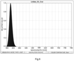
- Fig. 6 illustrates the spectral distribution of the blue light.
- the horizontal axis indicates the wavelength and the vertical axis the relative value.
- Fig. 6 demonstrates that the light source device according to the present technique can emit blue light with a wavelength of 375 to 445 nm, in specific, blue light having an emission peak at a wavelength of 404 nm.
- the light source device can emit blue light as described above. The intensity of the red fluorescent light from PpIX was then evaluated.
- the intensities of the red fluorescent light were compared with samples containing PpIX in different weights (10 ⁇ g, 1 ⁇ g, 0.2 ⁇ g, 0.1 ⁇ g, and 0 ⁇ g).
- the light source device according to the present technique was compared with a light source device (Aladuck ® available from SBI Pharmaceuticals Co., Ltd., hereinafter referred to as "comparative device") equipped with no concentrator.
- Fig. 7 shows the results.
- Photograph (a) shows red fluorescent light beams from PpIX in the samples after irradiation with blue light from the light source device according to the present technique.
- Photograph (b) shows red fluorescent light beams from PpIX in the samples after irradiation with blue light from the comparative device.
- the weights of PpIX in the samples are 10 ⁇ g, 1 ⁇ g, 0.2 ⁇ g, 0.1 ⁇ g, and 0 ⁇ g, from the left.
- Fig. 7 demonstrates that red fluorescent light necessary and sufficient for PDD can be emitted from 10 ⁇ g of PpIX in the samples using the light source device according to the present technique and the comparative device.
- the light source device In the comparison of the intensity of the red fluorescent light emitted from 1 ⁇ g of PpIX in the samples, the light source device according to the present technique detected higher intensity of light than the comparative device.
- the light source device In the comparison of the intensity of the red fluorescent light emitted from 0.2 ⁇ g of PpIX in the samples, the light source device according to the present technique detected a more significantly high intensity of light than the comparative device.
- the light source device can have the same or a higher detectability of red fluorescent light from PpIX than a traditional light source device suitable for PDD.
- the light source device according to the present technique can also have a high detectability of red fluorescent light from PpIX over a wider range of weight (a range of concentration of PpIX accumulated in a tumor site) compared to the traditional device.
Landscapes
- Health & Medical Sciences (AREA)
- Life Sciences & Earth Sciences (AREA)
- Physics & Mathematics (AREA)
- Surgery (AREA)
- Engineering & Computer Science (AREA)
- Optics & Photonics (AREA)
- Biomedical Technology (AREA)
- General Health & Medical Sciences (AREA)
- Public Health (AREA)
- Animal Behavior & Ethology (AREA)
- Nuclear Medicine, Radiotherapy & Molecular Imaging (AREA)
- Pathology (AREA)
- Veterinary Medicine (AREA)
- Radiology & Medical Imaging (AREA)
- Heart & Thoracic Surgery (AREA)
- Medical Informatics (AREA)
- Molecular Biology (AREA)
- Biophysics (AREA)
- General Physics & Mathematics (AREA)
- Microelectronics & Electronic Packaging (AREA)
- Astronomy & Astrophysics (AREA)
- Oral & Maxillofacial Surgery (AREA)
- Signal Processing (AREA)
- Multimedia (AREA)
- General Engineering & Computer Science (AREA)
- Endoscopes (AREA)
- Studio Devices (AREA)
- Investigating, Analyzing Materials By Fluorescence Or Luminescence (AREA)
- Investigating Or Analysing Materials By Optical Means (AREA)
- Instruments For Viewing The Inside Of Hollow Bodies (AREA)
- Lenses (AREA)
- Radiation-Therapy Devices (AREA)
- Measuring Pulse, Heart Rate, Blood Pressure Or Blood Flow (AREA)
- Non-Portable Lighting Devices Or Systems Thereof (AREA)
- Projection Apparatus (AREA)
Claims (12)
- Lichtquellenvorrichtung (1), die Folgendes umfasst:eine LED-Lichtquelle (11), die einen Lichtstrahl emittiert;einen Konzentrator, der ein Paar Fresnel-Linsen (12a, 12b) mit geriffelten Oberflächen aufweist und den emittierten Lichtstrahl konzentriert, wobei die geriffelten Oberflächen der Fresnel-Linsen einander zugewandt sind, undeinen Lichtleiter (13), der den konzentrierten Lichtstrahl führt, wobeidie geriffelten Oberflächen des Paars Fresnel-Linsen miteinander in Kontakt sind.
- LED-Lichtwellenvorrichtung nach Anspruch 1, wobei ein Ende des Lichtleiters im Wesentlichen in einem Brennpunkt des konzentrierten Lichtstrahls angeordnet ist.
- Lichtquellensystem (101), das Folgendes umfasst:eine erste LED-Lichtquelle (110a), die einen ersten Lichtstrahl emittiert;einen ersten Konzentrator (120a), der ein erstes Paar Fresnel-Linsen mit geriffelten Oberflächen aufweist und den ersten Lichtstrahl konzentriert, wobei die geriffelten Oberflächen der Fresnel-Linsen einander zugewandt sind;eine zweite LED-Lichtquelle (110b), die einen zweiten Lichtstrahl emittiert, der eine Wellenlänge hat, die von jener des ersten Lichtstrahls verschieden ist;einen zweiten Konzentrator (120b), der ein zweites Paar Fresnel-Linsen mit geriffelten Oberflächen aufweist und den zweiten Lichtstrahl konzentriert, wobei die geriffelten Oberflächen der Fresnel-Linsen einander zugewandt sind;einen Strahlteiler (140), der den ersten konzentrierten Lichtstrahl von dem ersten Konzentrator und den zweiten konzentrierten Lichtstrahl von dem zweiten Konzentrator teilt; undeinen Lichtleiter (130), der die geteilten Lichtstrahlen führt, wobeiein Ende des Lichtleiters im Wesentlichen in einem Brennpunkt des ersten konzentrierten Lichtstrahls und des zweiten konzentrierten Lichtstrahls, die bei dem Strahlteiler reflektiert und/oder durch diesen durchgelassen werden, um parallel gerichtet zu werden, angeordnet ist, unddie geriffelten Oberflächen des ersten Paars Fresnel-Linsen miteinander in Kontakt sind.
- Lichtquellensystem nach Anspruch 3, wobei die erste LED-Lichtquelle eine Quelle für weißes Licht ist und die zweite LED-Lichtquelle eine Quelle für Erregungslicht mit einer Wellenlänge von 375 bis 810 nm oder eine Quelle für Erregungslicht mit einer Wellenlänge von 750 bis 810 nm ist.
- Lichtquellensystem (101), das Folgendes umfasst:eine erste LED-Lichtquelle (110a), die einen ersten Lichtstrahl emittiert;einen ersten Konzentrator (120a), der ein erstes Paar Fresnel-Linsen mit geriffelten Oberflächen aufweist und den ersten Lichtstrahl konzentriert, wobei die geriffelten Oberflächen der Fresnel-Linsen einander zugewandt sind;eine zweite LED-Lichtquelle (110b), die einen zweiten Lichtstrahl emittiert, der eine Wellenlänge hat, die von jener des ersten Lichtstrahls verschieden ist;einen zweiten Konzentrator (120b), der ein zweites Paar Fresnel-Linsen mit geriffelten Oberflächen aufweist und den zweiten Lichtstrahl konzentriert, wobei die geriffelten Oberflächen der Fresnel-Linsen einander zugewandt sind;eine dritte LED-Lichtquelle, die einen dritten Lichtstrahl mit einer Wellenlänge, die von jenen des ersten und des zweiten Lichtstrahls verschieden ist, emittiert;einen dritten Konzentrator, der ein drittes Paar Fresnel-Linsen mit geriffelten Oberflächen aufweist und den dritten Lichtstrahl konzentriert, wobei die geriffelten Oberflächen der Fresnel-Linsen einander zugewandt sind;einen Strahlteiler (140), der den ersten konzentrierten Lichtstrahl von dem ersten Konzentrator, den zweiten konzentrierten Lichtstrahl von dem zweiten Konzentrator und den dritten konzentrierten Lichtstrahl von dem dritten Konzentrator teilt; undeinen Lichtleiter (130), der die geteilten Lichtstrahlen führt, wobeiein Ende des Lichtleiters im Wesentlichen in einem Brennpunkt von wenigstens zwei des ersten konzentrierten Lichtstrahls, des zweiten konzentrierten Lichtstrahls und des dritten konzentrierten Lichtstrahls, die bei dem Strahlteiler reflektiert und/oder durch diesen durchgelassen werden, um parallel gerichtet zu werden, angeordnet ist, unddie geriffelten Oberflächen des ersten Paars Fresnel-Linsen miteinander in Kontakt sind.
- Lichtquellensystem nach Anspruch 5, wobei die erste LED-Lichtquelle eine Quelle für weißes Licht ist, die zweite LED-Lichtquelle eine Quelle für Erregungslicht mit einer Wellenlänge von 375 bis 445 nm ist und die dritte LED-Lichtquelle für Erregungslicht mit einer Wellenlänge von 750 bis 810 nm ist.
- Medizinische Kamera, die Folgendes umfasst:ein Videoskop;einen Farbmonitor; unddas Lichtquellensystem (101) nach Anspruch 3 oder 4.
- Medizinische Kamera, die Folgendes umfasst:ein Videoskop;einen Farbmonitor; unddas Lichtquellensystem (101) nach Anspruch 5 oder 6.
- Fotodynamische diagnostische Vorrichtung, die die medizinische Kamera nach Anspruch 7 oder 8 enthält.
- Fotodynamische therapeutische Vorrichtung, die die medizinische Kamera nach Anspruch 7 oder 8 enthält.
- Fotodynamische diagnostische Vorrichtung, die die Lichtquellenvorrichtung (1) nach Anspruch 1 oder 2 enthält.
- Fotodynamische therapeutische Vorrichtung, die die Lichtquellenvorrichtung (1) nach Anspruch 1 oder 2 enthält.
Applications Claiming Priority (2)
| Application Number | Priority Date | Filing Date | Title |
|---|---|---|---|
| JP2020088504A JP6867533B1 (ja) | 2020-05-20 | 2020-05-20 | 光源装置 |
| PCT/JP2020/033528 WO2021145019A1 (ja) | 2020-05-20 | 2020-09-04 | 光源装置 |
Publications (4)
| Publication Number | Publication Date |
|---|---|
| EP3942994A1 EP3942994A1 (de) | 2022-01-26 |
| EP3942994A4 EP3942994A4 (de) | 2022-08-10 |
| EP3942994B1 true EP3942994B1 (de) | 2023-11-08 |
| EP3942994C0 EP3942994C0 (de) | 2023-11-08 |
Family
ID=75638931
Family Applications (1)
| Application Number | Title | Priority Date | Filing Date |
|---|---|---|---|
| EP20904264.7A Active EP3942994B1 (de) | 2020-05-20 | 2020-09-04 | Lichtquellenvorrichtung |
Country Status (10)
| Country | Link |
|---|---|
| US (1) | US11849922B2 (de) |
| EP (1) | EP3942994B1 (de) |
| JP (1) | JP6867533B1 (de) |
| KR (1) | KR102368406B1 (de) |
| CN (1) | CN113167992A (de) |
| BR (1) | BR112021017031B1 (de) |
| CA (1) | CA3122528C (de) |
| MX (1) | MX391821B (de) |
| TW (1) | TWI802879B (de) |
| WO (1) | WO2021145019A1 (de) |
Families Citing this family (1)
| Publication number | Priority date | Publication date | Assignee | Title |
|---|---|---|---|---|
| US12337190B2 (en) * | 2022-10-06 | 2025-06-24 | Olympus Medical Systems Corp. | Endoscope system and phototherapy method having a correction operation when an observation mode is set to a thermal suppression mode |
Family Cites Families (19)
| Publication number | Priority date | Publication date | Assignee | Title |
|---|---|---|---|---|
| TWI270670B (en) | 2003-05-12 | 2007-01-11 | De & T Co Ltd | Lighting apparatus for inspecting substrate |
| US7857619B2 (en) | 2005-02-26 | 2010-12-28 | Yongqian Liu | LED curing light having fresnel lenses |
| CN101021490B (zh) | 2007-03-12 | 2012-11-14 | 3i系统公司 | 平面基板自动检测系统及方法 |
| JP2008246078A (ja) | 2007-03-30 | 2008-10-16 | Hoya Corp | 内視鏡プロセッサおよび内視鏡システム |
| JP2010199027A (ja) * | 2009-02-27 | 2010-09-09 | Olympus Corp | 光源装置 |
| JP5055476B2 (ja) | 2009-11-18 | 2012-10-24 | シーシーエス株式会社 | 気象測定装置 |
| JP2012070822A (ja) | 2010-09-28 | 2012-04-12 | Fujifilm Corp | 光源装置および内視鏡診断装置 |
| JP5450339B2 (ja) | 2010-10-07 | 2014-03-26 | 富士フイルム株式会社 | 内視鏡用光源装置 |
| RU2670177C2 (ru) * | 2011-12-13 | 2018-10-18 | Филипс Лайтинг Холдинг Б.В. | Оптический коллиматор для светодиодных источников света |
| JP6129014B2 (ja) * | 2013-08-01 | 2017-05-17 | 日本板硝子株式会社 | 蛍光検出装置および蛍光検出方法 |
| JP6461797B2 (ja) * | 2013-08-23 | 2019-01-30 | オリンパス株式会社 | 蛍光観察装置 |
| JP6975704B2 (ja) * | 2015-02-03 | 2021-12-01 | 株式会社日立ハイテク | 多色検出装置 |
| KR101657887B1 (ko) * | 2015-03-30 | 2016-09-19 | 한국광기술원 | 내시경 광원모듈 |
| JP6359998B2 (ja) * | 2015-04-22 | 2018-07-18 | パナソニック株式会社 | 内視鏡 |
| JP6203436B2 (ja) | 2015-04-24 | 2017-09-27 | オリンパス株式会社 | 光源装置 |
| WO2017141417A1 (ja) | 2016-02-19 | 2017-08-24 | Hoya株式会社 | 内視鏡用光源装置 |
| CN107800478A (zh) | 2017-10-16 | 2018-03-13 | 唐义 | 一种用于多色移动可见光通信的白光发射天线 |
| WO2019198553A1 (en) | 2018-04-11 | 2019-10-17 | Sony Corporation | Microscope system and medical light source apparatus |
| JP6687071B2 (ja) | 2018-08-27 | 2020-04-22 | ソニー株式会社 | 照明装置、照明方法及び観察装置 |
-
2020
- 2020-05-20 JP JP2020088504A patent/JP6867533B1/ja active Active
- 2020-09-04 CA CA3122528A patent/CA3122528C/en active Active
- 2020-09-04 MX MX2021006918A patent/MX391821B/es unknown
- 2020-09-04 CN CN202080006380.3A patent/CN113167992A/zh active Pending
- 2020-09-04 US US17/299,667 patent/US11849922B2/en active Active
- 2020-09-04 WO PCT/JP2020/033528 patent/WO2021145019A1/ja not_active Ceased
- 2020-09-04 EP EP20904264.7A patent/EP3942994B1/de active Active
- 2020-09-04 BR BR112021017031-6A patent/BR112021017031B1/pt active IP Right Grant
- 2020-09-04 KR KR1020217015077A patent/KR102368406B1/ko active Active
-
2021
- 2021-05-10 TW TW110116748A patent/TWI802879B/zh active
Also Published As
| Publication number | Publication date |
|---|---|
| BR112021017031B1 (pt) | 2022-05-31 |
| EP3942994C0 (de) | 2023-11-08 |
| KR20210144652A (ko) | 2021-11-30 |
| WO2021145019A1 (ja) | 2021-07-22 |
| EP3942994A4 (de) | 2022-08-10 |
| CN113167992A (zh) | 2021-07-23 |
| MX2021006918A (es) | 2022-04-25 |
| TWI802879B (zh) | 2023-05-21 |
| BR112021017031A2 (pt) | 2022-01-25 |
| TW202145949A (zh) | 2021-12-16 |
| US20230190085A1 (en) | 2023-06-22 |
| KR102368406B1 (ko) | 2022-02-25 |
| JP6867533B1 (ja) | 2021-04-28 |
| CA3122528C (en) | 2022-01-04 |
| MX391821B (es) | 2025-03-21 |
| JP2021182978A (ja) | 2021-12-02 |
| US11849922B2 (en) | 2023-12-26 |
| CA3122528A1 (en) | 2021-08-25 |
| EP3942994A1 (de) | 2022-01-26 |
Similar Documents
| Publication | Publication Date | Title |
|---|---|---|
| US12461357B2 (en) | Multiple imaging modality light source | |
| US7328060B2 (en) | Cancer detection and adaptive dose optimization treatment system | |
| KR100798486B1 (ko) | 형광 진단 및 광역동치료를 위한 광원장치 | |
| US10908430B2 (en) | Medical imaging system, illumination device, and method | |
| JP2011156339A (ja) | 医療機器及び内視鏡装置 | |
| JP2002065602A (ja) | 照明光学系及び内視鏡装置 | |
| CN112198654B (zh) | 一种用于荧光影像导航手术的照明系统 | |
| EP3942994B1 (de) | Lichtquellenvorrichtung | |
| HK40063267B (en) | Light source device | |
| HK40063267A (en) | Light source device | |
| US10448817B2 (en) | Endoscopic device incorporating diode laser for PDD, PDT, and AF applications | |
| CN207693552U (zh) | 一种内窥式荧光观察装置 | |
| JP6973549B2 (ja) | 観察システム及び観察システムの制御方法 | |
| CN222787707U (zh) | 集荧光检测和光动力诊断于一体的内窥镜成像系统 | |
| HK40049047A (zh) | 光源装置 | |
| CN121408676A (zh) | 一种手术灯及光学手术指导系统 |
Legal Events
| Date | Code | Title | Description |
|---|---|---|---|
| STAA | Information on the status of an ep patent application or granted ep patent |
Free format text: STATUS: UNKNOWN |
|
| STAA | Information on the status of an ep patent application or granted ep patent |
Free format text: STATUS: THE INTERNATIONAL PUBLICATION HAS BEEN MADE |
|
| PUAI | Public reference made under article 153(3) epc to a published international application that has entered the european phase |
Free format text: ORIGINAL CODE: 0009012 |
|
| STAA | Information on the status of an ep patent application or granted ep patent |
Free format text: STATUS: REQUEST FOR EXAMINATION WAS MADE |
|
| 17P | Request for examination filed |
Effective date: 20210630 |
|
| AK | Designated contracting states |
Kind code of ref document: A1 Designated state(s): AL AT BE BG CH CY CZ DE DK EE ES FI FR GB GR HR HU IE IS IT LI LT LU LV MC MK MT NL NO PL PT RO RS SE SI SK SM TR |
|
| REG | Reference to a national code |
Ref country code: HK Ref legal event code: DE Ref document number: 40063267 Country of ref document: HK |
|
| A4 | Supplementary search report drawn up and despatched |
Effective date: 20220707 |
|
| RIC1 | Information provided on ipc code assigned before grant |
Ipc: F21V 5/04 20060101ALI20220701BHEP Ipc: H04N 5/232 20060101ALI20220701BHEP Ipc: H04N 5/225 20060101ALI20220701BHEP Ipc: G02B 23/24 20060101ALI20220701BHEP Ipc: G02B 19/00 20060101ALI20220701BHEP Ipc: G02B 6/42 20060101ALI20220701BHEP Ipc: G02B 3/08 20060101ALI20220701BHEP Ipc: A61B 90/30 20160101ALI20220701BHEP Ipc: A61B 1/07 20060101ALI20220701BHEP Ipc: A61B 1/04 20060101ALI20220701BHEP Ipc: A61B 1/00 20060101ALI20220701BHEP Ipc: A61B 1/06 20060101AFI20220701BHEP |
|
| REG | Reference to a national code |
Ref country code: DE Ref legal event code: R079 Free format text: PREVIOUS MAIN CLASS: A61B0001060000 Ipc: A61B0001000000 Ref country code: DE Ref legal event code: R079 Ref document number: 602020020891 Country of ref document: DE Free format text: PREVIOUS MAIN CLASS: A61B0001060000 Ipc: A61B0001000000 |
|
| GRAP | Despatch of communication of intention to grant a patent |
Free format text: ORIGINAL CODE: EPIDOSNIGR1 |
|
| STAA | Information on the status of an ep patent application or granted ep patent |
Free format text: STATUS: GRANT OF PATENT IS INTENDED |
|
| RIC1 | Information provided on ipc code assigned before grant |
Ipc: A61B 90/30 20160101ALN20230427BHEP Ipc: H04N 23/60 20230101ALI20230427BHEP Ipc: H04N 23/56 20230101ALI20230427BHEP Ipc: G02B 23/24 20060101ALI20230427BHEP Ipc: G02B 19/00 20060101ALI20230427BHEP Ipc: G02B 6/42 20060101ALI20230427BHEP Ipc: G02B 3/08 20060101ALI20230427BHEP Ipc: A61B 1/07 20060101ALI20230427BHEP Ipc: A61B 1/06 20060101ALI20230427BHEP Ipc: A61B 1/04 20060101ALI20230427BHEP Ipc: A61B 1/00 20060101AFI20230427BHEP |
|
| INTG | Intention to grant announced |
Effective date: 20230531 |
|
| DAV | Request for validation of the european patent (deleted) | ||
| DAX | Request for extension of the european patent (deleted) | ||
| GRAS | Grant fee paid |
Free format text: ORIGINAL CODE: EPIDOSNIGR3 |
|
| GRAA | (expected) grant |
Free format text: ORIGINAL CODE: 0009210 |
|
| STAA | Information on the status of an ep patent application or granted ep patent |
Free format text: STATUS: THE PATENT HAS BEEN GRANTED |
|
| AK | Designated contracting states |
Kind code of ref document: B1 Designated state(s): AL AT BE BG CH CY CZ DE DK EE ES FI FR GB GR HR HU IE IS IT LI LT LU LV MC MK MT NL NO PL PT RO RS SE SI SK SM TR |
|
| REG | Reference to a national code |
Ref country code: GB Ref legal event code: FG4D |
|
| REG | Reference to a national code |
Ref country code: CH Ref legal event code: EP |
|
| REG | Reference to a national code |
Ref country code: DE Ref legal event code: R096 Ref document number: 602020020891 Country of ref document: DE |
|
| REG | Reference to a national code |
Ref country code: IE Ref legal event code: FG4D |
|
| U01 | Request for unitary effect filed |
Effective date: 20231128 |
|
| U07 | Unitary effect registered |
Designated state(s): AT BE BG DE DK EE FI FR IT LT LU LV MT NL PT SE SI Effective date: 20231204 |
|
| PG25 | Lapsed in a contracting state [announced via postgrant information from national office to epo] |
Ref country code: GR Free format text: LAPSE BECAUSE OF FAILURE TO SUBMIT A TRANSLATION OF THE DESCRIPTION OR TO PAY THE FEE WITHIN THE PRESCRIBED TIME-LIMIT Effective date: 20240209 |
|
| PG25 | Lapsed in a contracting state [announced via postgrant information from national office to epo] |
Ref country code: IS Free format text: LAPSE BECAUSE OF FAILURE TO SUBMIT A TRANSLATION OF THE DESCRIPTION OR TO PAY THE FEE WITHIN THE PRESCRIBED TIME-LIMIT Effective date: 20240308 |
|
| PG25 | Lapsed in a contracting state [announced via postgrant information from national office to epo] |
Ref country code: ES Free format text: LAPSE BECAUSE OF FAILURE TO SUBMIT A TRANSLATION OF THE DESCRIPTION OR TO PAY THE FEE WITHIN THE PRESCRIBED TIME-LIMIT Effective date: 20231108 |
|
| PG25 | Lapsed in a contracting state [announced via postgrant information from national office to epo] |
Ref country code: IS Free format text: LAPSE BECAUSE OF FAILURE TO SUBMIT A TRANSLATION OF THE DESCRIPTION OR TO PAY THE FEE WITHIN THE PRESCRIBED TIME-LIMIT Effective date: 20240308 Ref country code: GR Free format text: LAPSE BECAUSE OF FAILURE TO SUBMIT A TRANSLATION OF THE DESCRIPTION OR TO PAY THE FEE WITHIN THE PRESCRIBED TIME-LIMIT Effective date: 20240209 Ref country code: ES Free format text: LAPSE BECAUSE OF FAILURE TO SUBMIT A TRANSLATION OF THE DESCRIPTION OR TO PAY THE FEE WITHIN THE PRESCRIBED TIME-LIMIT Effective date: 20231108 |
|
| PG25 | Lapsed in a contracting state [announced via postgrant information from national office to epo] |
Ref country code: RS Free format text: LAPSE BECAUSE OF FAILURE TO SUBMIT A TRANSLATION OF THE DESCRIPTION OR TO PAY THE FEE WITHIN THE PRESCRIBED TIME-LIMIT Effective date: 20231108 Ref country code: PL Free format text: LAPSE BECAUSE OF FAILURE TO SUBMIT A TRANSLATION OF THE DESCRIPTION OR TO PAY THE FEE WITHIN THE PRESCRIBED TIME-LIMIT Effective date: 20231108 Ref country code: NO Free format text: LAPSE BECAUSE OF FAILURE TO SUBMIT A TRANSLATION OF THE DESCRIPTION OR TO PAY THE FEE WITHIN THE PRESCRIBED TIME-LIMIT Effective date: 20240208 Ref country code: HR Free format text: LAPSE BECAUSE OF FAILURE TO SUBMIT A TRANSLATION OF THE DESCRIPTION OR TO PAY THE FEE WITHIN THE PRESCRIBED TIME-LIMIT Effective date: 20231108 |
|
| PG25 | Lapsed in a contracting state [announced via postgrant information from national office to epo] |
Ref country code: CZ Free format text: LAPSE BECAUSE OF FAILURE TO SUBMIT A TRANSLATION OF THE DESCRIPTION OR TO PAY THE FEE WITHIN THE PRESCRIBED TIME-LIMIT Effective date: 20231108 |
|
| PG25 | Lapsed in a contracting state [announced via postgrant information from national office to epo] |
Ref country code: SK Free format text: LAPSE BECAUSE OF FAILURE TO SUBMIT A TRANSLATION OF THE DESCRIPTION OR TO PAY THE FEE WITHIN THE PRESCRIBED TIME-LIMIT Effective date: 20231108 |
|
| PG25 | Lapsed in a contracting state [announced via postgrant information from national office to epo] |
Ref country code: SM Free format text: LAPSE BECAUSE OF FAILURE TO SUBMIT A TRANSLATION OF THE DESCRIPTION OR TO PAY THE FEE WITHIN THE PRESCRIBED TIME-LIMIT Effective date: 20231108 Ref country code: SK Free format text: LAPSE BECAUSE OF FAILURE TO SUBMIT A TRANSLATION OF THE DESCRIPTION OR TO PAY THE FEE WITHIN THE PRESCRIBED TIME-LIMIT Effective date: 20231108 Ref country code: RO Free format text: LAPSE BECAUSE OF FAILURE TO SUBMIT A TRANSLATION OF THE DESCRIPTION OR TO PAY THE FEE WITHIN THE PRESCRIBED TIME-LIMIT Effective date: 20231108 Ref country code: CZ Free format text: LAPSE BECAUSE OF FAILURE TO SUBMIT A TRANSLATION OF THE DESCRIPTION OR TO PAY THE FEE WITHIN THE PRESCRIBED TIME-LIMIT Effective date: 20231108 |
|
| REG | Reference to a national code |
Ref country code: DE Ref legal event code: R097 Ref document number: 602020020891 Country of ref document: DE |
|
| U20 | Renewal fee for the european patent with unitary effect paid |
Year of fee payment: 5 Effective date: 20240807 |
|
| PLBE | No opposition filed within time limit |
Free format text: ORIGINAL CODE: 0009261 |
|
| STAA | Information on the status of an ep patent application or granted ep patent |
Free format text: STATUS: NO OPPOSITION FILED WITHIN TIME LIMIT |
|
| 26N | No opposition filed |
Effective date: 20240809 |
|
| PG25 | Lapsed in a contracting state [announced via postgrant information from national office to epo] |
Ref country code: MC Free format text: LAPSE BECAUSE OF FAILURE TO SUBMIT A TRANSLATION OF THE DESCRIPTION OR TO PAY THE FEE WITHIN THE PRESCRIBED TIME-LIMIT Effective date: 20231108 |
|
| REG | Reference to a national code |
Ref country code: CH Ref legal event code: PL |
|
| PG25 | Lapsed in a contracting state [announced via postgrant information from national office to epo] |
Ref country code: CH Free format text: LAPSE BECAUSE OF NON-PAYMENT OF DUE FEES Effective date: 20240930 |
|
| PG25 | Lapsed in a contracting state [announced via postgrant information from national office to epo] |
Ref country code: IE Free format text: LAPSE BECAUSE OF NON-PAYMENT OF DUE FEES Effective date: 20240904 |
|
| U20 | Renewal fee for the european patent with unitary effect paid |
Year of fee payment: 6 Effective date: 20250807 |
|
| PGFP | Annual fee paid to national office [announced via postgrant information from national office to epo] |
Ref country code: GB Payment date: 20250731 Year of fee payment: 6 |
|
| PG25 | Lapsed in a contracting state [announced via postgrant information from national office to epo] |
Ref country code: CY Free format text: LAPSE BECAUSE OF FAILURE TO SUBMIT A TRANSLATION OF THE DESCRIPTION OR TO PAY THE FEE WITHIN THE PRESCRIBED TIME-LIMIT; INVALID AB INITIO Effective date: 20200904 |
|
| PG25 | Lapsed in a contracting state [announced via postgrant information from national office to epo] |
Ref country code: HU Free format text: LAPSE BECAUSE OF FAILURE TO SUBMIT A TRANSLATION OF THE DESCRIPTION OR TO PAY THE FEE WITHIN THE PRESCRIBED TIME-LIMIT; INVALID AB INITIO Effective date: 20200904 |