EP3941835B1 - Maschine und verfahren zur herstellung von beuteln mit kohäsionsfreiem material - Google Patents
Maschine und verfahren zur herstellung von beuteln mit kohäsionsfreiem material Download PDFInfo
- Publication number
- EP3941835B1 EP3941835B1 EP19721737.5A EP19721737A EP3941835B1 EP 3941835 B1 EP3941835 B1 EP 3941835B1 EP 19721737 A EP19721737 A EP 19721737A EP 3941835 B1 EP3941835 B1 EP 3941835B1
- Authority
- EP
- European Patent Office
- Prior art keywords
- transfer drum
- machine
- station
- rotation axis
- rotating hub
- Prior art date
- Legal status (The legal status is an assumption and is not a legal conclusion. Google has not performed a legal analysis and makes no representation as to the accuracy of the status listed.)
- Active
Links
Images


Classifications
-
- B—PERFORMING OPERATIONS; TRANSPORTING
- B65—CONVEYING; PACKING; STORING; HANDLING THIN OR FILAMENTARY MATERIAL
- B65B—MACHINES, APPARATUS OR DEVICES FOR, OR METHODS OF, PACKAGING ARTICLES OR MATERIALS; UNPACKING
- B65B1/00—Packaging fluent solid material, e.g. powders, granular or loose fibrous material, loose masses of small articles, in individual containers or receptacles, e.g. bags, sacks, boxes, cartons, cans, or jars
- B65B1/04—Methods of, or means for, filling the material into the containers or receptacles
- B65B1/06—Methods of, or means for, filling the material into the containers or receptacles by gravity flow
-
- B—PERFORMING OPERATIONS; TRANSPORTING
- B65—CONVEYING; PACKING; STORING; HANDLING THIN OR FILAMENTARY MATERIAL
- B65B—MACHINES, APPARATUS OR DEVICES FOR, OR METHODS OF, PACKAGING ARTICLES OR MATERIALS; UNPACKING
- B65B11/00—Wrapping, e.g. partially or wholly enclosing, articles or quantities of material, in strips, sheets or blanks, of flexible material
- B65B11/48—Enclosing articles, or quantities of material, by folding a wrapper, e.g. a pocketed wrapper, and securing its opposed free margins to enclose contents
-
- B—PERFORMING OPERATIONS; TRANSPORTING
- B65—CONVEYING; PACKING; STORING; HANDLING THIN OR FILAMENTARY MATERIAL
- B65B—MACHINES, APPARATUS OR DEVICES FOR, OR METHODS OF, PACKAGING ARTICLES OR MATERIALS; UNPACKING
- B65B29/00—Packaging of materials presenting special problems
- B65B29/02—Packaging of substances, e.g. tea, which are intended to be infused in the package
- B65B29/028—Packaging of substances, e.g. tea, which are intended to be infused in the package packaging infusion material into filter bags
-
- B—PERFORMING OPERATIONS; TRANSPORTING
- B65—CONVEYING; PACKING; STORING; HANDLING THIN OR FILAMENTARY MATERIAL
- B65B—MACHINES, APPARATUS OR DEVICES FOR, OR METHODS OF, PACKAGING ARTICLES OR MATERIALS; UNPACKING
- B65B37/00—Supplying or feeding fluent-solid, plastic, or liquid material, or loose masses of small articles, to be packaged
- B65B37/02—Supplying or feeding fluent-solid, plastic, or liquid material, or loose masses of small articles, to be packaged by gravity flow
-
- B—PERFORMING OPERATIONS; TRANSPORTING
- B65—CONVEYING; PACKING; STORING; HANDLING THIN OR FILAMENTARY MATERIAL
- B65B—MACHINES, APPARATUS OR DEVICES FOR, OR METHODS OF, PACKAGING ARTICLES OR MATERIALS; UNPACKING
- B65B37/00—Supplying or feeding fluent-solid, plastic, or liquid material, or loose masses of small articles, to be packaged
- B65B37/08—Supplying or feeding fluent-solid, plastic, or liquid material, or loose masses of small articles, to be packaged by rotary feeders
-
- B—PERFORMING OPERATIONS; TRANSPORTING
- B65—CONVEYING; PACKING; STORING; HANDLING THIN OR FILAMENTARY MATERIAL
- B65B—MACHINES, APPARATUS OR DEVICES FOR, OR METHODS OF, PACKAGING ARTICLES OR MATERIALS; UNPACKING
- B65B51/00—Devices for, or methods of, sealing or securing package folds or closures; Devices for gathering or twisting wrappers, or necks of bags
- B65B51/10—Applying or generating heat or pressure or combinations thereof
- B65B51/16—Applying or generating heat or pressure or combinations thereof by rotary members
-
- B—PERFORMING OPERATIONS; TRANSPORTING
- B65—CONVEYING; PACKING; STORING; HANDLING THIN OR FILAMENTARY MATERIAL
- B65B—MACHINES, APPARATUS OR DEVICES FOR, OR METHODS OF, PACKAGING ARTICLES OR MATERIALS; UNPACKING
- B65B51/00—Devices for, or methods of, sealing or securing package folds or closures; Devices for gathering or twisting wrappers, or necks of bags
- B65B51/10—Applying or generating heat or pressure or combinations thereof
- B65B51/26—Devices specially adapted for producing transverse or longitudinal seams in webs or tubes
-
- B—PERFORMING OPERATIONS; TRANSPORTING
- B65—CONVEYING; PACKING; STORING; HANDLING THIN OR FILAMENTARY MATERIAL
- B65B—MACHINES, APPARATUS OR DEVICES FOR, OR METHODS OF, PACKAGING ARTICLES OR MATERIALS; UNPACKING
- B65B2210/00—Specific aspects of the packaging machine
- B65B2210/10—Means for removing bridges formed by the material or article, e.g. anti-clogging devices
Definitions
- the present invention relates to a machine and a process for manufacturing pouches containing a cohesionless material as powder or fibers, for example coffee, tea, cellulose fibers and others.
- a cohesionless material as powder or fibers, for example coffee, tea, cellulose fibers and others.
- the invention is particularly applicable for the use with fibers having a dimension comprised between 50 and 250 ⁇ m.
- the prior art embraces machines where a transfer drum is used to pick up a material from an accumulation zone and to transport the material, in the form of a continuous stream, to a delivery station where a succession of portions of the stream is separated in a discrete way. Each portion, constituting a dose, is then enclosed in a pouch and sealed according to known flowpack methods.
- Such machines are generally provided for use with fiber materials, for example tobacco, which are held by suction onto the outer surfaces of the transfer drum from the accumulation zone to the delivery station.
- the suction drum is furnished on its periphery with a series of through suction holes which are connected to an internal suction chamber of the drum.
- These drums are designed for an optimized action on such fiber materials and it has been shown that they do not correctly work on cohesionless materials having small dimension particles.
- the holes on the suction drum have a diameter of 0.5 mm or more, which is enough to provide a sufficient suction holding of tobacco fibers with, at the same time, an easy workability of the outer mantle of the drum.
- This structure of the known transfer drums does not allow for a correct and reliable use of cohesionless materials of granular or powder form, or even a fiber form, having smaller dimension. These materials have the tendency to reach the suction chamber within the transfer drum and to collect therein due to their smaller dimension than the suction holes, on one side, and to stick together at the accumulation zone, on the other side. This leads to undesired clogging of the entire machine that must repeatedly be stopped to allow for a manual removal of the clogged portions.
- the object of the present invention is to overcome the drawbacks described above.
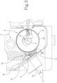
- numeral 1 denotes a machine used in the manufacture of pouches 2 containing a cohesionless material.
- the cohesionless material can be in the form of powder or fibers and is made of particles having a dimension comprised between 50 ⁇ m and 250 ⁇ m.
- the material can be coffee powder, tea particles from leaves, cellulose fibers.
- the machine 1 comprises a hopper 3 serving as means of storing and feeding the material by gravity, connected by way of conveyor means 4 on which to form a continuous stream 5 of the mixture, and by a rectilinear duct 6, to a wrapping and sealing station 7 where the pouches 2 are fashioned.
- Such conveyor means 4 comprise a transfer drum 8 rotatable about a horizontal rotation axis 9, presenting a cylindrical wall 10 and enclosed by two mutually opposed side walls 11 (one only of which is visible in figure 1 ).
- the drum 8 rotates intermittently about the axis 9 in a clockwise direction, as viewed in the drawings, through steps of predetermined angular distance, and is arranged between a pick-up station 12, located below the hopper 3 and where the transfer drum 8 picks up the material, and a release station 13 downstream of the pick-up station 12 where portions of the material forming part of the stream 5 are delivered from the transfer drum 8 to the rectilinear duct 6.
- the pick-up station 12 comprises a nip 14 defined between a part of the cylindrical wall 10 of the transfer drum 8 and a side wall 15 so that the cylindrical wall 10 and the side wall 15 laterally delimit the nip 14 on opposite sides.
- the side wall 15 can be defined by a part of a containing structure which surrounds the nip 14 and a vertical channel above, from which the material falls by gravity after exiting the hopper 3.
- the nip can be replaced by a generic accumulation zone where a sufficient quantity of material is accumulated so that the transfer drum 8 can enter in contact with the accumulated material so as to pick-up the material and form the aforementioned continuous stream 5 on the transfer drum 8.
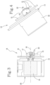
- the machine 1 further comprises a mixer 16 or agitator, located at the pick-up station 12, in particular at least partly arranged in the nip 14 or more generally in the accumulation zone and configured for performing a mixing action on the material (in the nip 14) immediately before the material is picked up by the transfer drum 8.
- a mixer 16 or agitator located at the pick-up station 12, in particular at least partly arranged in the nip 14 or more generally in the accumulation zone and configured for performing a mixing action on the material (in the nip 14) immediately before the material is picked up by the transfer drum 8.
- the mixer 16 is mounted on the side wall 15, preferably in a cantilevered manner, and arranged in such a way that it is at least covered by the material collected by gravity in the nip 14.
- the mixer 16 comprises a rotating hub 17 which is mounted for rotation about a respective rotation axis 18 and is coupled with a pneumatic actuator or an electric motor 19 for setting the hub 17 in rotation about the axis 18 and which can be enclosed in a respective housing 20.
- the rotating hub 17 is located in a position facing the cylindrical wall 10 of the transfer drum 8.
- the hub 17 can be rotated continuously or intermittently in either a clockwise or anti-clockwise direction, as viewed in the figures, or can oscillate through steps of predetermined angular distance.
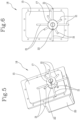
- pins 21 ( figures 3-6 ) which are arranged perpendicularly (or anyway transversely) to the rotation axis 18 of the rotating hub 17.
- the pins 21 are mounted on the rotating hub 17 at different positions along the rotation axis 18 of the rotating hub 17, preferably in such a way that for each position along the axis 18 more than one pin 21 is arranged on the rotating hub 17 according to an angular distribution about the rotation axis 18 of the rotating hub 17.
- two or more sections can be identified, where two or more pins 21 are arranged and angularly distributed about the axis 18 so as to prevent cohesionless material compaction.
- two positions are shown and at each position four pins 21 are arranged, equally distributed at an angular spacing of 90°.
- the pins 21 of different positions can be angularly shifted, as for example in the embodiments of figures 3-6 the four pins of one position are angularly shifted of 45° with respect to the four pins 21 of the other position.
- the pins 21 have a round or elliptical section or can have a section shaped in a fashion to allow the free passage of the hub 17 with the pins 21 through the cohesionless material in the nip 14 without altering the properties of the material. Moreover, the pins 21 are preferably mounted on the hub 17 in a freely rotating manner about their longitudinal axis or, alternatively, the pins 21 can be fixed to the hub 17. The longitudinal axes of the pins 21 is transversal or perpendicular (generally "radial") to the rotation axis 18 of the hub 17.
- the pins 21 have respective lengths, measured perpendicularly with respect to the rotation axis 18 of the rotating hub 17, which decrease along the rotation axis 18 of the rotating hub 17 and in particular in a direction away from the side wall 15 and towards the transfer drum 8.
- This configuration confers to the mixer 16 a generally tapered configuration towards the transfer drum 8.
- the second stage of pins is furnished with shorter pins than the first stage. This assists in the advancement of the cohesionless material towards the transfer drum 8.
- the mixer 16 further comprises at least one additional pin 22 which is arranged with its main axis transversal, but not perpendicular, to the rotation axis 18 of the rotating hub 17.
- This additional pin 22 is located in a closer position to the transfer drum 8 and projects towards the transfer drum 8, preferably beyond the front edge of the rotating hub 17, so as to perform a stirring action on the material in the nip 14.
- the at least one additional pin 22 constitutes a last stage (third stage in this case) where the additional pin 22 moves to define a conical outline.
- the side wall 15, and in particular at least a portion thereof to which the mixer is mounted has a planar or flat configuration.
- the side wall 15 lays on a plane which is inclined of a base angle " ⁇ 1 " with respect to a vertical plane which includes the rotating axis 9 of the transfer drum 8.
- ⁇ 1 a downwards tapered shape
- the base angle " ⁇ 1 " is comprised between 20° and 70° and preferably comprised between 40° and 50°.
- the rotation axis 18 of the rotating hub 17 lays in a vertical plane and is inclined of a mixing angle " ⁇ 2 " with respect to a horizontal plane.
- the mixing angle " ⁇ 2 " is comprised between 20° and 70° and preferably comprised between 40° and 50°.
- the rotation axis 18 of the rotating hub 17 is perpendicular to the side wall 15.
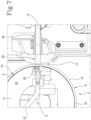
- the cylindrical wall 10 of the drum 8 presents one or more circumferential grooves 23 ( figure 8 ) of annular shape and predetermined width.
- the invention is applicable to multi-track transfer drums having any number of circumferential grooves as well, where the grooves are axially spaced along the rotation axis 9 of the transfer drum 8 as shown in figure 8 .
- the circumferential groove 23 is furnished along its entire circumferential length with through holes 24 (only partly shown in figure 7 ) communicating with an internal chamber of the transfer drum 8 to transfer the material in the form of continuous streams.
- the additional pin 22 sweeps in an arc from each circumferential groove 23 within the transfer drum 8 to prevent voids from developing within the continuous streams 5 as the cohesionless material is vacuumed into the circumferential grooves 23 of the rotating drum 8.
- the through holes 24 are formed as apertures in the cylindrical wall 10 of the transfer drum 8, for example by laser techniques. This holes are shown in figure 9A(1).
- the holes have a diameter or a transverse section less than 200 ⁇ m and preferably less than 50 ⁇ m.
- the circumferential groove 23 is equipped with a circumferential permeable strip applied to the transfer drum 8 and having through openings smaller than 200 ⁇ m and preferably smaller than 50 ⁇ m.
- the circumferential permeable strip can made of a dense wire mesh, as in figure 9A(2), or can be made of a printed or sintered metal, as in figure 9A(3).
- the machine 1 can further comprise a scraping member "S" adjacent to the transfer drum 8 for scraping the material of the continuous stream 5 transferred by the transfer drum 8 from the pick-up station 12 to the release station 13.
- a scraping member "S" adjacent to the transfer drum 8 for scraping the material of the continuous stream 5 transferred by the transfer drum 8 from the pick-up station 12 to the release station 13.
- the scraping member "S” is preferably in the form of a rotating roller having a cylindrical outline and a rotation axis parallel to the rotation axis 9 of the transfer drum 8.
- the scraping member "S” can have a non-cylindrical outline, for example by having a polygonal section.
- the internal chamber of the transfer drum 8 is divided into a first sector 25 and a second sector 26 ( figure 7 ).
- the second sector 26, which extends through an arc of predetermined width, is sandwiched between the two ends of the first sector 25 and positioned to coincide with the release station 13.
- the first sector 25 is connected by way of a duct (not shown) to a source of negative pressure so that the through holes 24 of the circumferential groove 23 act as suction holes to retain the continuous stream 5 of material into the groove 23.
- the second sector 26 is connected via a duct 27 to a pneumatic source (not shown) to perform shots of compressed air by which segments of the stream 5 are separated from the transfer drum 8 to be delivered to the rectilinear duct 6.
- the rectilinear duct 6 comprises an inlet portion or mouth 28 of funnelform appearance, facing the sector of the drum coinciding with the transfer station 13, and a tubular body 29 ( figure 7 ).
- a tubular envelope of paper wrapping material (unwound from a roll, not illustrated) is fashioned through the agency of conventional folding means (not illustrated).
- the tubular envelope is sealed longitudinally by first sealing means 30 ( figure 1 ).
- second sealing means 31 operating downstream of the first sealing means 30 and comprising, in the shown embodiment, an upper set of three heated sealing anvils and a lower set of three heated sealing anvils, spring loaded each other to provide the sealing function.
- the upper set of sealing anvils contains a knurled pattern along the sealing surface while the lower set can have just a smooth sealing surface.
- the cohesionless material released from the hopper 3 is collected into the nip 14 and picked up from the transfer drum 8 so that a continuous stream 5 is formed in the circumferential groove 23.
- a (preferably continuous) rotation movement of the mixer 16 assists in maintaining a correct homogeneous form of the material in the nip 14 so as to avoid any clogging of the machine.
- the continuous stream 5 advances into the transfer station 13 where, with each step indexed by the drum 8 (in a clockwise direction), a jet of compressed air is delivered at the second sector 17 through the relative holes 24, causing a segment of the stream 5 to be ejected from the groove 23.
- a jet of compressed air is delivered at the second sector 17 through the relative holes 24, causing a segment of the stream 5 to be ejected from the groove 23.
- the transfer drum 8 completes one indexed rotation step in the clockwise direction
- the transfer drum 8 then rotates back in a counter-clockwise direction for another predetermined angle (usually 10°). This allows in clearing the holes 24 within the drum 8 to prevent the new start wall of the cohesionless stream 5 from falling into the empty portion of the channel that has been ejected.
- This last cleaning action prevents any excessive cohesionless material from falling into the air stream and also ensures consistent product dosing and helps in keeping the end seal of the pouch clear of product at the end of a pouch cycle.
- the segment of material is directed by the compressed air through the funnelform mouth 28 into the tubular body 29 of the rectilinear feed duct 6.
- the ejected segment is of predetermined length corresponding to a single wrappable portion or dose of material.
- the tubular envelope is closed up longitudinally by the first sealing means 30.
- the tubular envelope containing the successive portions of material is engaged transversely by the second sealing means 31, operating intermittently and timed to match the frequency with which the portions are ejected, in such a way that each portion will be enclosed between two successive transverse seals.
- the invention achieves the advantage of producing pouches filled with a cohesionless material having a very small particle size (from 50 to 250 ⁇ m) with a high level of reliability, in particular reducing the risks of clogging of the machine which is usually caused by the use of such small particles.
- the mixer allows to maintain a state of fluidity without altering the cohesionless material.
- the mixer also allows the cohesionless material to easily advance towards the transfer drum minimizing voids within the body of the cohesionless material. This also leads to an optimized and consistent stream being maintained along the annular grooves of the transfer drum.
Landscapes
- Engineering & Computer Science (AREA)
- Mechanical Engineering (AREA)
- Making Paper Articles (AREA)
- Containers And Plastic Fillers For Packaging (AREA)
Claims (25)
- Maschine zur Herstellung von Beuteln enthaltend ein kohäsionsfreies Material, umfassend Zuführungsmittel (3) zum Zuführen des kohäsionsfreien Materials zu einer Aufnahmestation (12), eine Transfertrommel (8), mittels derer das Material an der Aufnahmestation (12) aufgenommen und an eine Freigabestation (13) transferiert wird, Übergabemittel (18), die an der Freigabestation (13) arbeiten und mittels derer Abschnitte des Materials von der Transfertrommel (8) durch eine Leitung (6) an eine Einwickelstation (7) übergeben werden, an der die Abschnitte in Beutel (2) gesiegelt werden,
dadurch gekennzeichnet, dass die Maschine (1) zudem einen Mischer (16) umfasst, der an der Aufnahmestation (12) befindlich ist, um einen Mischvorgang auf dem Material an der Aufnahmestation (12) durchzuführen, bevor das Material von der Transfertrommel (8) aufgenommen wird. - Maschine nach Anspruch 1, wobei die Aufnahmestation (12) einen Spalt (14) umfasst, der zwischen einem Teil einer äußeren zylindrischen Wand (10) der Transfertrommel (8) und einer Seitenwand (15) definiert ist, wobei die Zuführungsmittel (3) ausgelegt sind, um das Material im Spalt (14) vorzugsweise per Schwerkraft freizugeben, und wobei der Mischer (16) mindestens teilweise im Spalt (14) angeordnet ist.
- Maschine nach Anspruch 1 oder 2, wobei der Mischer (16) auskragend auf der Seitenwand (15) montiert ist.
- Maschine nach Anspruch 2 oder 3, wobei der Mischer (16) eine rotierende Nabe (17) und einen oder mehrere Zapfen (21) umfasst, die auf der rotierenden Nabe (17) montiert und quer und/oder senkrecht zur Rotationsachse (18) der rotierenden Nabe (17) angeordnet sind.
- Maschine nach Anspruch 4, wobei die Zapfen (21) auf der rotierenden Nabe (17) an unterschiedlichen Positionen entlang der Rotationsachse (18) der rotierenden Nabe (17) montiert sind und wobei die Zapfen (21) jeweilige Längen aufweisen, senkrecht gemessen in Bezug auf die Rotationsachse (18) der rotierenden Nabe (17), die entlang der Rotationsachse (18) der rotierenden Nabe (17) abnehmen.
- Maschine nach Anspruch 5, wobei die rotierende Nabe (17) in einer einander zugewandten Beziehung in Bezug auf die Transfertrommel (8) angeordnet ist und wobei die jeweiligen Längen der Zapfen (21) entlang der Rotationsachse (18) der rotierenden Nabe (17) hinführend zur Transfertrommel (8) abnehmen.
- Maschine nach Anspruch 5 oder 6, wobei für jede Position entlang der Rotationsachse (18) der rotierenden Nabe (17) mehr als ein Zapfen (21) auf der rotierenden Nabe (17) nach einer winkeligen Verteilung um die Rotationsachse (18) der rotierenden Nabe (17) angeordnet ist.
- Maschine nach einem der Ansprüche 4 bis 7, wobei mindestens einige der Zapfen (21) mit den jeweiligen Hauptachsen senkrecht zur Rotationsachse (18) der rotierenden Nabe (17) angeordnet sind.
- Maschine nach Anspruch 8, zudem umfassend mindestens einen zusätzlichen Zapfen (22), der mit seiner Hauptachse quer, jedoch nicht senkrecht zur Rotationsachse (18) der rotierenden Nabe (17) angeordnet ist.
- Maschine nach Anspruch 9, wenn abhängig von Anspruch 6, wobei der zusätzliche Zapfen (22) in einer näheren Position an der Transfertrommel (8) befindlich ist und hinführend zur Transfertrommel (8) hervorspringt, sodass ein Rührvorgang auf dem Material im Spalt (14) durchgeführt wird.
- Maschine nach einem der Ansprüche 2 bis 10, wobei sich die Transfertrommel (8) um eine horizontale Rotationsachse (9) dreht, die in einer vertikalen Ebene liegt, und wobei die Seitenwand (15) auf einer Ebene liegt, die in Bezug auf die vertikale Ebene um einen Basiswinkel (α1) geneigt ist.
- Maschine nach Anspruch 11, wobei der Basiswinkel (α1) zwischen 20° und 70° eingeschlossen und vorzugsweise zwischen 40° and 50° eingeschlossen ist.
- Maschine nach einem der Ansprüche 2 bis 10, wobei sich die Transfertrommel (8) um eine horizontale Rotationsachse (9) dreht und wobei die Rotationsachse (18) der rotierenden Nabe (17) in einer vertikalen Ebene liegt und in Bezug auf eine horizontale Ebene um einen Mischwinkel (α2) geneigt ist.
- Maschine nach Anspruch 13, wobei der Mischwinkel (α2) zwischen 20° und 70° eingeschlossen und vorzugsweise zwischen 40° and 50° eingeschlossen ist.
- Maschine nach einem der Ansprüche 2 bis 14, wobei die Seitenwand (15) flach ist und wobei die Rotationsachse (18) der rotierenden Nabe (17) senkrecht zur Seitenwand (15) angeordnet ist.
- Maschine nach einem der Ansprüche 1 bis 14, umfassend ein Schaberelement (S), das an die Transfertrommel (8) angrenzt, um das durch die Transfertrommel (8) von der Aufnahmestation (12) zur Freigabestation (13) transferierte Material abzuschaben.
- Maschine nach Anspruch 16, wobei das Schaberelement (S) eine rotierende Walze ist, die einen zylindrischen Umriss und eine Rotationsachse aufweist, die parallel zur Rotationsachse (9) der Transfertrommel (8) angeordnet ist.
- Maschine nach einem der vorhergehenden Ansprüche, wobei die Transfertrommel (8) mindestens eine umfangseitige Rille (23) zum Halten des Materials in der Form eines durchgehenden Stroms (5) von Material von der Aufnahmestation (12) zur Freigabestation (13) aufweist, und wobei die umfangseitige Rille (23) Sauglöcher (24) aufweist, die mit mindestens einer internen Saugkammer (25) der Transfertrommel (8) kommunizieren und einen Durchmesser oder eine Querabmessung von weniger als 50 µm aufweisen.
- Maschine nach einem der Ansprüche 1 bis 17, wobei die Transfertrommel (8) mindestens eine umfangseitige Rille (23) zum Halten des Materials in der Form eines durchgehenden Stroms (5) von Material von der Aufnahmestation (12) zur Freigabestation (13) aufweist, und wobei die umfangseitige Rille (23) mit einem umfangseitigen durchlässigen Streifen ausgestattet ist, der an der Transfertrommel (8) angebracht ist, und aufweisend Durchführungsöffnungen, die kleiner als 200 µm und vorzugsweise kleiner als 50 µm sind, wobei die Durchführungsöffnungen mit mindestens einer internen Saugkammer (25) der Transfertrommel (8) kommunizieren.
- Maschine nach Anspruch 19, wobei der umfangseitige durchlässige Streifen aus einem dichten Drahtmaschengewebe gefertigt ist.
- Maschine nach Anspruch 20, wobei der umfangseitige durchlässige Streifen aus einem gedruckten oder gesinterten Material gefertigt ist.
- Maschine nach den Ansprüchen 18 bis 21, wobei die Transfertrommel (8) als mehrbahniger Förderer ausgelegt ist und zwei oder mehr umfangseitige Rillen (23) aufweist, die axial entlang der Rotationsachse (9) der Transfertrommel (8) beabstandet sind.
- Verfahren zur Herstellung von Beuteln enthaltend ein kohäsionsfreies Material, umfassend das Zuführen von kohäsionsfreiem Material, bestehend aus Partikeln mit einer Abmessung von 50 µm bis 250 µm eingeschlossen bis zu einer Aufnahmestation (12), das Aufnehmen des Materials an der Aufnahmestation (12) durch eine Transfertrommel (8) und das Transferieren des Materials in der Form eines durchgehenden Stroms (5) mittels der Transfertrommel (8) zu einer Freigabestation (13), wo das Material durch eine Leitung (6) an eine Einwickelstation (7) übergeben wird, an der die Abschnitte in Beutel (2) gesiegelt werden,
dadurch gekennzeichnet, dass das Verfahren zudem einen Schritt zum Mischen des Materials in der Aufnahmestation (12) mittels eines Mischers (16) umfasst, bevor das Material mittels der Transfertrommel (8) aufgenommen wird. - Verfahren nach Anspruch 23, wobei die Schritte zum Aufnehmen des Materials von der Aufnahmestation (12) und zum Transferieren des Materials hinführend zur Freigabestation (13) mittels der Transfertrommel (8) durchgeführt wird, indem eine Transfertrommel (8) genutzt wird, die mindestens eine umfangseitige Rille (23) mit Saugöffnungen (24) aufweist, wobei die Saugöffnungen (24) einen Durchmesser oder eine Querabmessung aufweisen, die kleiner als 200 µm und vorzugsweise kleiner als 50 µm ist.
- Verfahren nach Anspruch 23 oder 24, durchgeführt mit einer Maschine (1) nach einem der Ansprüche 1 bis 22.
Applications Claiming Priority (1)
| Application Number | Priority Date | Filing Date | Title |
|---|---|---|---|
| PCT/IB2019/052248 WO2020188320A1 (en) | 2019-03-20 | 2019-03-20 | A machine and a process for manufacturing pouches containing a cohesionless material |
Publications (2)
| Publication Number | Publication Date |
|---|---|
| EP3941835A1 EP3941835A1 (de) | 2022-01-26 |
| EP3941835B1 true EP3941835B1 (de) | 2024-08-07 |
Family
ID=66397302
Family Applications (1)
| Application Number | Title | Priority Date | Filing Date |
|---|---|---|---|
| EP19721737.5A Active EP3941835B1 (de) | 2019-03-20 | 2019-03-20 | Maschine und verfahren zur herstellung von beuteln mit kohäsionsfreiem material |
Country Status (4)
| Country | Link |
|---|---|
| US (2) | US11981462B2 (de) |
| EP (1) | EP3941835B1 (de) |
| PL (1) | PL3941835T3 (de) |
| WO (1) | WO2020188320A1 (de) |
Families Citing this family (2)
| Publication number | Priority date | Publication date | Assignee | Title |
|---|---|---|---|---|
| EP3941835B1 (de) * | 2019-03-20 | 2024-08-07 | G.D S.p.A. | Maschine und verfahren zur herstellung von beuteln mit kohäsionsfreiem material |
| IT202200014578A1 (it) * | 2022-07-12 | 2024-01-12 | Sasib Spa | Macchina impacchettatrice per la produzione di bustine ciascuna contenente una dose di un prodotto incoerente |
Family Cites Families (9)
| Publication number | Priority date | Publication date | Assignee | Title |
|---|---|---|---|---|
| GB295560A (en) | 1928-03-12 | 1928-08-16 | John Thomas Dalton | Improvements in bag making and filling machines |
| US4571924A (en) * | 1985-04-29 | 1986-02-25 | The Procter & Gamble Company | Method and apparatus of manufacturing porous pouches containing granular product |
| EP0226939B1 (de) | 1985-12-10 | 1992-11-19 | Kimberly-Clark Corporation | Vorrichtung und Verfahren für die Erzeugung eines Faservlieses |
| ITBO20070196A1 (it) | 2007-03-20 | 2008-09-21 | Azionaria Costruzioni Acma Spa | Macchina e metodo per la produzione di bustine di materiale incoerente. |
| ITBO20070197A1 (it) * | 2007-03-20 | 2008-09-21 | Azionaria Costruzioni Acma Spa | Macchina per la produzione di bustine di materiale incoerente. |
| ITBO20070198A1 (it) * | 2007-03-20 | 2008-09-21 | Azionaria Costruzioni Acma Spa | Dispositivo di lavaggio in macchine per la produzione di singole bustine di materiale incoerente ed in impianti per il confezionamento di porzioni di melassa di tabacco. |
| ITBO20070195A1 (it) | 2007-03-20 | 2008-09-21 | Azionaria Costruzioni Acma Spa | Metodo per il confezionamento di melassa di tabacco e relativo impianto. |
| ITBO20070688A1 (it) * | 2007-10-12 | 2009-04-13 | Azionaria Costruzioni Acma Spa | Macchina per la produzione di bustine contenenti una miscela di tabacco. |
| EP3941835B1 (de) * | 2019-03-20 | 2024-08-07 | G.D S.p.A. | Maschine und verfahren zur herstellung von beuteln mit kohäsionsfreiem material |
-
2019
- 2019-03-20 EP EP19721737.5A patent/EP3941835B1/de active Active
- 2019-03-20 US US17/432,252 patent/US11981462B2/en active Active
- 2019-03-20 PL PL19721737.5T patent/PL3941835T3/pl unknown
- 2019-03-20 WO PCT/IB2019/052248 patent/WO2020188320A1/en not_active Ceased
-
2024
- 2024-04-04 US US18/627,009 patent/US12338016B2/en active Active
Also Published As
| Publication number | Publication date |
|---|---|
| US20240308702A1 (en) | 2024-09-19 |
| WO2020188320A1 (en) | 2020-09-24 |
| PL3941835T3 (pl) | 2024-10-21 |
| US11981462B2 (en) | 2024-05-14 |
| US12338016B2 (en) | 2025-06-24 |
| US20220169405A1 (en) | 2022-06-02 |
| EP3941835A1 (de) | 2022-01-26 |
Similar Documents
| Publication | Publication Date | Title |
|---|---|---|
| US12338016B2 (en) | Machine and a process for manufacturing pouches containing a cohesionless material | |
| EP2097320B1 (de) | Verfahren zur herstellung von beuteln für kohäsionsfreies material | |
| US8297031B2 (en) | Machine and a method for manufacturing pouches of cohesionless material | |
| KR101521671B1 (ko) | 비드 공급장치 | |
| KR101513320B1 (ko) | 비드 공급장치 | |
| JP4290000B2 (ja) | 計量された量の粒子材料で空洞を充填するデュアルステーションアプリケータホイール | |
| US20100210437A1 (en) | Vertical filter filling machine and process | |
| JP6051217B2 (ja) | たばこ産業の設備におけるばら物質をピックアップする装置、かかる装置のスクレーパ、及びばら物質を供給する方法 | |
| US6723033B1 (en) | Method and apparatus for producing particle bearing filter rod | |
| JP4431284B2 (ja) | 粒子支持フィルタ・ロッドを製造するための方法および装置 | |
| JPH0229309B2 (de) | ||
| US3196880A (en) | Cigarette making machine | |
| EP3661376B1 (de) | Verfahren und vorrichtung zur herstellung eines filterstabs mit mikrokügelchen | |
| US2290896A (en) | Dense end mechanism for cigarette machines | |
| CN114052286B (zh) | 用于进给珠状物的进给单元以及用于制造杆的设备 | |
| WO2025153727A1 (en) | Tobacco industry apparatus for the production of tobacco industry rods |
Legal Events
| Date | Code | Title | Description |
|---|---|---|---|
| STAA | Information on the status of an ep patent application or granted ep patent |
Free format text: STATUS: UNKNOWN |
|
| STAA | Information on the status of an ep patent application or granted ep patent |
Free format text: STATUS: THE INTERNATIONAL PUBLICATION HAS BEEN MADE |
|
| PUAI | Public reference made under article 153(3) epc to a published international application that has entered the european phase |
Free format text: ORIGINAL CODE: 0009012 |
|
| STAA | Information on the status of an ep patent application or granted ep patent |
Free format text: STATUS: REQUEST FOR EXAMINATION WAS MADE |
|
| 17P | Request for examination filed |
Effective date: 20210818 |
|
| AK | Designated contracting states |
Kind code of ref document: A1 Designated state(s): AL AT BE BG CH CY CZ DE DK EE ES FI FR GB GR HR HU IE IS IT LI LT LU LV MC MK MT NL NO PL PT RO RS SE SI SK SM TR |
|
| DAV | Request for validation of the european patent (deleted) | ||
| DAX | Request for extension of the european patent (deleted) | ||
| P01 | Opt-out of the competence of the unified patent court (upc) registered |
Effective date: 20230528 |
|
| GRAP | Despatch of communication of intention to grant a patent |
Free format text: ORIGINAL CODE: EPIDOSNIGR1 |
|
| STAA | Information on the status of an ep patent application or granted ep patent |
Free format text: STATUS: GRANT OF PATENT IS INTENDED |
|
| INTG | Intention to grant announced |
Effective date: 20240313 |
|
| GRAS | Grant fee paid |
Free format text: ORIGINAL CODE: EPIDOSNIGR3 |
|
| GRAA | (expected) grant |
Free format text: ORIGINAL CODE: 0009210 |
|
| STAA | Information on the status of an ep patent application or granted ep patent |
Free format text: STATUS: THE PATENT HAS BEEN GRANTED |
|
| AK | Designated contracting states |
Kind code of ref document: B1 Designated state(s): AL AT BE BG CH CY CZ DE DK EE ES FI FR GB GR HR HU IE IS IT LI LT LU LV MC MK MT NL NO PL PT RO RS SE SI SK SM TR |
|
| REG | Reference to a national code |
Ref country code: GB Ref legal event code: FG4D |
|
| REG | Reference to a national code |
Ref country code: CH Ref legal event code: EP |
|
| REG | Reference to a national code |
Ref country code: IE Ref legal event code: FG4D |
|
| REG | Reference to a national code |
Ref country code: DE Ref legal event code: R096 Ref document number: 602019056532 Country of ref document: DE |
|
| REG | Reference to a national code |
Ref country code: LT Ref legal event code: MG9D |
|
| REG | Reference to a national code |
Ref country code: NL Ref legal event code: MP Effective date: 20240807 |
|
| PG25 | Lapsed in a contracting state [announced via postgrant information from national office to epo] |
Ref country code: NO Free format text: LAPSE BECAUSE OF FAILURE TO SUBMIT A TRANSLATION OF THE DESCRIPTION OR TO PAY THE FEE WITHIN THE PRESCRIBED TIME-LIMIT Effective date: 20241107 |
|
| REG | Reference to a national code |
Ref country code: AT Ref legal event code: MK05 Ref document number: 1710678 Country of ref document: AT Kind code of ref document: T Effective date: 20240807 |
|
| PG25 | Lapsed in a contracting state [announced via postgrant information from national office to epo] |
Ref country code: FI Free format text: LAPSE BECAUSE OF FAILURE TO SUBMIT A TRANSLATION OF THE DESCRIPTION OR TO PAY THE FEE WITHIN THE PRESCRIBED TIME-LIMIT Effective date: 20240807 Ref country code: NL Free format text: LAPSE BECAUSE OF FAILURE TO SUBMIT A TRANSLATION OF THE DESCRIPTION OR TO PAY THE FEE WITHIN THE PRESCRIBED TIME-LIMIT Effective date: 20240807 Ref country code: PT Free format text: LAPSE BECAUSE OF FAILURE TO SUBMIT A TRANSLATION OF THE DESCRIPTION OR TO PAY THE FEE WITHIN THE PRESCRIBED TIME-LIMIT Effective date: 20241209 Ref country code: GR Free format text: LAPSE BECAUSE OF FAILURE TO SUBMIT A TRANSLATION OF THE DESCRIPTION OR TO PAY THE FEE WITHIN THE PRESCRIBED TIME-LIMIT Effective date: 20241108 |
|
| PG25 | Lapsed in a contracting state [announced via postgrant information from national office to epo] |
Ref country code: BG Free format text: LAPSE BECAUSE OF FAILURE TO SUBMIT A TRANSLATION OF THE DESCRIPTION OR TO PAY THE FEE WITHIN THE PRESCRIBED TIME-LIMIT Effective date: 20240807 |
|
| PG25 | Lapsed in a contracting state [announced via postgrant information from national office to epo] |
Ref country code: LV Free format text: LAPSE BECAUSE OF FAILURE TO SUBMIT A TRANSLATION OF THE DESCRIPTION OR TO PAY THE FEE WITHIN THE PRESCRIBED TIME-LIMIT Effective date: 20240807 |
|
| PG25 | Lapsed in a contracting state [announced via postgrant information from national office to epo] |
Ref country code: AT Free format text: LAPSE BECAUSE OF FAILURE TO SUBMIT A TRANSLATION OF THE DESCRIPTION OR TO PAY THE FEE WITHIN THE PRESCRIBED TIME-LIMIT Effective date: 20240807 Ref country code: IS Free format text: LAPSE BECAUSE OF FAILURE TO SUBMIT A TRANSLATION OF THE DESCRIPTION OR TO PAY THE FEE WITHIN THE PRESCRIBED TIME-LIMIT Effective date: 20241207 |
|
| PG25 | Lapsed in a contracting state [announced via postgrant information from national office to epo] |
Ref country code: HR Free format text: LAPSE BECAUSE OF FAILURE TO SUBMIT A TRANSLATION OF THE DESCRIPTION OR TO PAY THE FEE WITHIN THE PRESCRIBED TIME-LIMIT Effective date: 20240807 |
|
| PG25 | Lapsed in a contracting state [announced via postgrant information from national office to epo] |
Ref country code: ES Free format text: LAPSE BECAUSE OF FAILURE TO SUBMIT A TRANSLATION OF THE DESCRIPTION OR TO PAY THE FEE WITHIN THE PRESCRIBED TIME-LIMIT Effective date: 20240807 Ref country code: RS Free format text: LAPSE BECAUSE OF FAILURE TO SUBMIT A TRANSLATION OF THE DESCRIPTION OR TO PAY THE FEE WITHIN THE PRESCRIBED TIME-LIMIT Effective date: 20241107 |
|
| PG25 | Lapsed in a contracting state [announced via postgrant information from national office to epo] |
Ref country code: RS Free format text: LAPSE BECAUSE OF FAILURE TO SUBMIT A TRANSLATION OF THE DESCRIPTION OR TO PAY THE FEE WITHIN THE PRESCRIBED TIME-LIMIT Effective date: 20241107 Ref country code: PT Free format text: LAPSE BECAUSE OF FAILURE TO SUBMIT A TRANSLATION OF THE DESCRIPTION OR TO PAY THE FEE WITHIN THE PRESCRIBED TIME-LIMIT Effective date: 20241209 Ref country code: NO Free format text: LAPSE BECAUSE OF FAILURE TO SUBMIT A TRANSLATION OF THE DESCRIPTION OR TO PAY THE FEE WITHIN THE PRESCRIBED TIME-LIMIT Effective date: 20241107 Ref country code: NL Free format text: LAPSE BECAUSE OF FAILURE TO SUBMIT A TRANSLATION OF THE DESCRIPTION OR TO PAY THE FEE WITHIN THE PRESCRIBED TIME-LIMIT Effective date: 20240807 Ref country code: LV Free format text: LAPSE BECAUSE OF FAILURE TO SUBMIT A TRANSLATION OF THE DESCRIPTION OR TO PAY THE FEE WITHIN THE PRESCRIBED TIME-LIMIT Effective date: 20240807 Ref country code: IS Free format text: LAPSE BECAUSE OF FAILURE TO SUBMIT A TRANSLATION OF THE DESCRIPTION OR TO PAY THE FEE WITHIN THE PRESCRIBED TIME-LIMIT Effective date: 20241207 Ref country code: HR Free format text: LAPSE BECAUSE OF FAILURE TO SUBMIT A TRANSLATION OF THE DESCRIPTION OR TO PAY THE FEE WITHIN THE PRESCRIBED TIME-LIMIT Effective date: 20240807 Ref country code: GR Free format text: LAPSE BECAUSE OF FAILURE TO SUBMIT A TRANSLATION OF THE DESCRIPTION OR TO PAY THE FEE WITHIN THE PRESCRIBED TIME-LIMIT Effective date: 20241108 Ref country code: FI Free format text: LAPSE BECAUSE OF FAILURE TO SUBMIT A TRANSLATION OF THE DESCRIPTION OR TO PAY THE FEE WITHIN THE PRESCRIBED TIME-LIMIT Effective date: 20240807 Ref country code: ES Free format text: LAPSE BECAUSE OF FAILURE TO SUBMIT A TRANSLATION OF THE DESCRIPTION OR TO PAY THE FEE WITHIN THE PRESCRIBED TIME-LIMIT Effective date: 20240807 Ref country code: BG Free format text: LAPSE BECAUSE OF FAILURE TO SUBMIT A TRANSLATION OF THE DESCRIPTION OR TO PAY THE FEE WITHIN THE PRESCRIBED TIME-LIMIT Effective date: 20240807 Ref country code: AT Free format text: LAPSE BECAUSE OF FAILURE TO SUBMIT A TRANSLATION OF THE DESCRIPTION OR TO PAY THE FEE WITHIN THE PRESCRIBED TIME-LIMIT Effective date: 20240807 |
|
| PG25 | Lapsed in a contracting state [announced via postgrant information from national office to epo] |
Ref country code: DK Free format text: LAPSE BECAUSE OF FAILURE TO SUBMIT A TRANSLATION OF THE DESCRIPTION OR TO PAY THE FEE WITHIN THE PRESCRIBED TIME-LIMIT Effective date: 20240807 Ref country code: SM Free format text: LAPSE BECAUSE OF FAILURE TO SUBMIT A TRANSLATION OF THE DESCRIPTION OR TO PAY THE FEE WITHIN THE PRESCRIBED TIME-LIMIT Effective date: 20240807 Ref country code: RO Free format text: LAPSE BECAUSE OF FAILURE TO SUBMIT A TRANSLATION OF THE DESCRIPTION OR TO PAY THE FEE WITHIN THE PRESCRIBED TIME-LIMIT Effective date: 20240807 |
|
| PG25 | Lapsed in a contracting state [announced via postgrant information from national office to epo] |
Ref country code: EE Free format text: LAPSE BECAUSE OF FAILURE TO SUBMIT A TRANSLATION OF THE DESCRIPTION OR TO PAY THE FEE WITHIN THE PRESCRIBED TIME-LIMIT Effective date: 20240807 |
|
| PG25 | Lapsed in a contracting state [announced via postgrant information from national office to epo] |
Ref country code: CZ Free format text: LAPSE BECAUSE OF FAILURE TO SUBMIT A TRANSLATION OF THE DESCRIPTION OR TO PAY THE FEE WITHIN THE PRESCRIBED TIME-LIMIT Effective date: 20240807 |
|
| PGFP | Annual fee paid to national office [announced via postgrant information from national office to epo] |
Ref country code: PL Payment date: 20250305 Year of fee payment: 7 |
|
| PG25 | Lapsed in a contracting state [announced via postgrant information from national office to epo] |
Ref country code: SK Free format text: LAPSE BECAUSE OF FAILURE TO SUBMIT A TRANSLATION OF THE DESCRIPTION OR TO PAY THE FEE WITHIN THE PRESCRIBED TIME-LIMIT Effective date: 20240807 |
|
| REG | Reference to a national code |
Ref country code: DE Ref legal event code: R097 Ref document number: 602019056532 Country of ref document: DE |
|
| PLBE | No opposition filed within time limit |
Free format text: ORIGINAL CODE: 0009261 |
|
| STAA | Information on the status of an ep patent application or granted ep patent |
Free format text: STATUS: NO OPPOSITION FILED WITHIN TIME LIMIT |
|
| 26N | No opposition filed |
Effective date: 20250508 |
|
| PG25 | Lapsed in a contracting state [announced via postgrant information from national office to epo] |
Ref country code: SE Free format text: LAPSE BECAUSE OF FAILURE TO SUBMIT A TRANSLATION OF THE DESCRIPTION OR TO PAY THE FEE WITHIN THE PRESCRIBED TIME-LIMIT Effective date: 20240807 |
|
| PG25 | Lapsed in a contracting state [announced via postgrant information from national office to epo] |
Ref country code: MC Free format text: LAPSE BECAUSE OF FAILURE TO SUBMIT A TRANSLATION OF THE DESCRIPTION OR TO PAY THE FEE WITHIN THE PRESCRIBED TIME-LIMIT Effective date: 20240807 |
|
| REG | Reference to a national code |
Ref country code: CH Ref legal event code: H13 Free format text: ST27 STATUS EVENT CODE: U-0-0-H10-H13 (AS PROVIDED BY THE NATIONAL OFFICE) Effective date: 20251023 |
|
| PG25 | Lapsed in a contracting state [announced via postgrant information from national office to epo] |
Ref country code: LU Free format text: LAPSE BECAUSE OF NON-PAYMENT OF DUE FEES Effective date: 20250320 |
|
| GBPC | Gb: european patent ceased through non-payment of renewal fee |
Effective date: 20250320 |
|
| REG | Reference to a national code |
Ref country code: BE Ref legal event code: MM Effective date: 20250331 |
|
| PG25 | Lapsed in a contracting state [announced via postgrant information from national office to epo] |
Ref country code: GB Free format text: LAPSE BECAUSE OF NON-PAYMENT OF DUE FEES Effective date: 20250320 |
|
| PG25 | Lapsed in a contracting state [announced via postgrant information from national office to epo] |
Ref country code: FR Free format text: LAPSE BECAUSE OF NON-PAYMENT OF DUE FEES Effective date: 20250331 |
|
| PG25 | Lapsed in a contracting state [announced via postgrant information from national office to epo] |
Ref country code: BE Free format text: LAPSE BECAUSE OF NON-PAYMENT OF DUE FEES Effective date: 20250331 |
|
| PG25 | Lapsed in a contracting state [announced via postgrant information from national office to epo] |
Ref country code: CH Free format text: LAPSE BECAUSE OF NON-PAYMENT OF DUE FEES Effective date: 20250331 |
|
| PG25 | Lapsed in a contracting state [announced via postgrant information from national office to epo] |
Ref country code: IE Free format text: LAPSE BECAUSE OF NON-PAYMENT OF DUE FEES Effective date: 20250320 |
|
| PG25 | Lapsed in a contracting state [announced via postgrant information from national office to epo] |
Ref country code: IT Free format text: LAPSE BECAUSE OF FAILURE TO SUBMIT A TRANSLATION OF THE DESCRIPTION OR TO PAY THE FEE WITHIN THE PRESCRIBED TIME-LIMIT Effective date: 20240807 |
|
| PGFP | Annual fee paid to national office [announced via postgrant information from national office to epo] |
Ref country code: DE Payment date: 20260327 Year of fee payment: 8 |