EP3941622B1 - Photokatalysator - Google Patents
Photokatalysator Download PDFInfo
- Publication number
- EP3941622B1 EP3941622B1 EP20715171.3A EP20715171A EP3941622B1 EP 3941622 B1 EP3941622 B1 EP 3941622B1 EP 20715171 A EP20715171 A EP 20715171A EP 3941622 B1 EP3941622 B1 EP 3941622B1
- Authority
- EP
- European Patent Office
- Prior art keywords
- base material
- photocatalyst
- group
- transition metals
- viii
- Prior art date
- Legal status (The legal status is an assumption and is not a legal conclusion. Google has not performed a legal analysis and makes no representation as to the accuracy of the status listed.)
- Active
Links
Images


Classifications
-
- B—PERFORMING OPERATIONS; TRANSPORTING
- B01—PHYSICAL OR CHEMICAL PROCESSES OR APPARATUS IN GENERAL
- B01J—CHEMICAL OR PHYSICAL PROCESSES, e.g. CATALYSIS OR COLLOID CHEMISTRY; THEIR RELEVANT APPARATUS
- B01J35/00—Catalysts, in general, characterised by their form or physical properties
- B01J35/30—Catalysts, in general, characterised by their form or physical properties characterised by their physical properties
- B01J35/39—Photocatalytic properties
-
- B—PERFORMING OPERATIONS; TRANSPORTING
- B01—PHYSICAL OR CHEMICAL PROCESSES OR APPARATUS IN GENERAL
- B01J—CHEMICAL OR PHYSICAL PROCESSES, e.g. CATALYSIS OR COLLOID CHEMISTRY; THEIR RELEVANT APPARATUS
- B01J23/00—Catalysts comprising metals or metal oxides or hydroxides, not provided for in group B01J21/00
- B01J23/16—Catalysts comprising metals or metal oxides or hydroxides, not provided for in group B01J21/00 of arsenic, antimony, bismuth, vanadium, niobium, tantalum, polonium, chromium, molybdenum, tungsten, manganese, technetium or rhenium
- B01J23/24—Chromium, molybdenum or tungsten
- B01J23/28—Molybdenum
-
- B—PERFORMING OPERATIONS; TRANSPORTING
- B01—PHYSICAL OR CHEMICAL PROCESSES OR APPARATUS IN GENERAL
- B01J—CHEMICAL OR PHYSICAL PROCESSES, e.g. CATALYSIS OR COLLOID CHEMISTRY; THEIR RELEVANT APPARATUS
- B01J23/00—Catalysts comprising metals or metal oxides or hydroxides, not provided for in group B01J21/00
- B01J23/16—Catalysts comprising metals or metal oxides or hydroxides, not provided for in group B01J21/00 of arsenic, antimony, bismuth, vanadium, niobium, tantalum, polonium, chromium, molybdenum, tungsten, manganese, technetium or rhenium
- B01J23/24—Chromium, molybdenum or tungsten
- B01J23/30—Tungsten
-
- B—PERFORMING OPERATIONS; TRANSPORTING
- B01—PHYSICAL OR CHEMICAL PROCESSES OR APPARATUS IN GENERAL
- B01J—CHEMICAL OR PHYSICAL PROCESSES, e.g. CATALYSIS OR COLLOID CHEMISTRY; THEIR RELEVANT APPARATUS
- B01J23/00—Catalysts comprising metals or metal oxides or hydroxides, not provided for in group B01J21/00
- B01J23/38—Catalysts comprising metals or metal oxides or hydroxides, not provided for in group B01J21/00 of noble metals
- B01J23/54—Catalysts comprising metals or metal oxides or hydroxides, not provided for in group B01J21/00 of noble metals combined with metals, oxides or hydroxides provided for in groups B01J23/02 - B01J23/36
- B01J23/56—Platinum group metals
- B01J23/64—Platinum group metals with arsenic, antimony, bismuth, vanadium, niobium, tantalum, polonium, chromium, molybdenum, tungsten, manganese, technetium or rhenium
- B01J23/652—Chromium, molybdenum or tungsten
-
- B—PERFORMING OPERATIONS; TRANSPORTING
- B01—PHYSICAL OR CHEMICAL PROCESSES OR APPARATUS IN GENERAL
- B01J—CHEMICAL OR PHYSICAL PROCESSES, e.g. CATALYSIS OR COLLOID CHEMISTRY; THEIR RELEVANT APPARATUS
- B01J23/00—Catalysts comprising metals or metal oxides or hydroxides, not provided for in group B01J21/00
- B01J23/70—Catalysts comprising metals or metal oxides or hydroxides, not provided for in group B01J21/00 of the iron group metals or copper
- B01J23/76—Catalysts comprising metals or metal oxides or hydroxides, not provided for in group B01J21/00 of the iron group metals or copper combined with metals, oxides or hydroxides provided for in groups B01J23/02 - B01J23/36
- B01J23/84—Catalysts comprising metals or metal oxides or hydroxides, not provided for in group B01J21/00 of the iron group metals or copper combined with metals, oxides or hydroxides provided for in groups B01J23/02 - B01J23/36 with arsenic, antimony, bismuth, vanadium, niobium, tantalum, polonium, chromium, molybdenum, tungsten, manganese, technetium or rhenium
- B01J23/85—Chromium, molybdenum or tungsten
-
- B—PERFORMING OPERATIONS; TRANSPORTING
- B01—PHYSICAL OR CHEMICAL PROCESSES OR APPARATUS IN GENERAL
- B01J—CHEMICAL OR PHYSICAL PROCESSES, e.g. CATALYSIS OR COLLOID CHEMISTRY; THEIR RELEVANT APPARATUS
- B01J27/00—Catalysts comprising the elements or compounds of halogens, sulfur, selenium, tellurium, phosphorus or nitrogen; Catalysts comprising carbon compounds
- B01J27/02—Sulfur, selenium or tellurium; Compounds thereof
- B01J27/04—Sulfides
- B01J27/047—Sulfides with chromium, molybdenum, tungsten or polonium
- B01J27/051—Molybdenum
- B01J27/0515—Molybdenum with iron group metals or platinum group metals
-
- B—PERFORMING OPERATIONS; TRANSPORTING
- B01—PHYSICAL OR CHEMICAL PROCESSES OR APPARATUS IN GENERAL
- B01J—CHEMICAL OR PHYSICAL PROCESSES, e.g. CATALYSIS OR COLLOID CHEMISTRY; THEIR RELEVANT APPARATUS
- B01J27/00—Catalysts comprising the elements or compounds of halogens, sulfur, selenium, tellurium, phosphorus or nitrogen; Catalysts comprising carbon compounds
- B01J27/02—Sulfur, selenium or tellurium; Compounds thereof
- B01J27/057—Selenium or tellurium; Compounds thereof
-
- B—PERFORMING OPERATIONS; TRANSPORTING
- B01—PHYSICAL OR CHEMICAL PROCESSES OR APPARATUS IN GENERAL
- B01J—CHEMICAL OR PHYSICAL PROCESSES, e.g. CATALYSIS OR COLLOID CHEMISTRY; THEIR RELEVANT APPARATUS
- B01J35/00—Catalysts, in general, characterised by their form or physical properties
- B01J35/40—Catalysts, in general, characterised by their form or physical properties characterised by dimensions, e.g. grain size
- B01J35/45—Nanoparticles
-
- B—PERFORMING OPERATIONS; TRANSPORTING
- B01—PHYSICAL OR CHEMICAL PROCESSES OR APPARATUS IN GENERAL
- B01J—CHEMICAL OR PHYSICAL PROCESSES, e.g. CATALYSIS OR COLLOID CHEMISTRY; THEIR RELEVANT APPARATUS
- B01J35/00—Catalysts, in general, characterised by their form or physical properties
- B01J35/50—Catalysts, in general, characterised by their form or physical properties characterised by their shape or configuration
-
- B—PERFORMING OPERATIONS; TRANSPORTING
- B01—PHYSICAL OR CHEMICAL PROCESSES OR APPARATUS IN GENERAL
- B01J—CHEMICAL OR PHYSICAL PROCESSES, e.g. CATALYSIS OR COLLOID CHEMISTRY; THEIR RELEVANT APPARATUS
- B01J37/00—Processes, in general, for preparing catalysts; Processes, in general, for activation of catalysts
- B01J37/02—Impregnation, coating or precipitation
- B01J37/0201—Impregnation
- B01J37/0207—Pretreatment of the support
-
- B—PERFORMING OPERATIONS; TRANSPORTING
- B01—PHYSICAL OR CHEMICAL PROCESSES OR APPARATUS IN GENERAL
- B01J—CHEMICAL OR PHYSICAL PROCESSES, e.g. CATALYSIS OR COLLOID CHEMISTRY; THEIR RELEVANT APPARATUS
- B01J37/00—Processes, in general, for preparing catalysts; Processes, in general, for activation of catalysts
- B01J37/02—Impregnation, coating or precipitation
- B01J37/0201—Impregnation
- B01J37/0209—Impregnation involving a reaction between the support and a fluid
-
- B—PERFORMING OPERATIONS; TRANSPORTING
- B01—PHYSICAL OR CHEMICAL PROCESSES OR APPARATUS IN GENERAL
- B01J—CHEMICAL OR PHYSICAL PROCESSES, e.g. CATALYSIS OR COLLOID CHEMISTRY; THEIR RELEVANT APPARATUS
- B01J37/00—Processes, in general, for preparing catalysts; Processes, in general, for activation of catalysts
- B01J37/02—Impregnation, coating or precipitation
- B01J37/024—Multiple impregnation or coating
-
- B—PERFORMING OPERATIONS; TRANSPORTING
- B01—PHYSICAL OR CHEMICAL PROCESSES OR APPARATUS IN GENERAL
- B01J—CHEMICAL OR PHYSICAL PROCESSES, e.g. CATALYSIS OR COLLOID CHEMISTRY; THEIR RELEVANT APPARATUS
- B01J37/00—Processes, in general, for preparing catalysts; Processes, in general, for activation of catalysts
- B01J37/34—Irradiation by, or application of, electric, magnetic or wave energy, e.g. ultrasonic waves ; Ionic sputtering; Flame or plasma spraying; Particle radiation
- B01J37/341—Irradiation by, or application of, electric, magnetic or wave energy, e.g. ultrasonic waves ; Ionic sputtering; Flame or plasma spraying; Particle radiation making use of electric or magnetic fields, wave energy or particle radiation
- B01J37/343—Irradiation by, or application of, electric, magnetic or wave energy, e.g. ultrasonic waves ; Ionic sputtering; Flame or plasma spraying; Particle radiation making use of electric or magnetic fields, wave energy or particle radiation of ultrasonic wave energy
-
- C—CHEMISTRY; METALLURGY
- C01—INORGANIC CHEMISTRY
- C01C—AMMONIA; CYANOGEN; COMPOUNDS THEREOF
- C01C1/00—Ammonia; Compounds thereof
- C01C1/02—Preparation, purification or separation of ammonia
-
- C—CHEMISTRY; METALLURGY
- C01—INORGANIC CHEMISTRY
- C01C—AMMONIA; CYANOGEN; COMPOUNDS THEREOF
- C01C1/00—Ammonia; Compounds thereof
- C01C1/02—Preparation, purification or separation of ammonia
- C01C1/04—Preparation of ammonia by synthesis in the gas phase
- C01C1/0405—Preparation of ammonia by synthesis in the gas phase from N2 and H2 in presence of a catalyst
- C01C1/0411—Preparation of ammonia by synthesis in the gas phase from N2 and H2 in presence of a catalyst characterised by the catalyst
-
- C—CHEMISTRY; METALLURGY
- C01—INORGANIC CHEMISTRY
- C01C—AMMONIA; CYANOGEN; COMPOUNDS THEREOF
- C01C1/00—Ammonia; Compounds thereof
- C01C1/02—Preparation, purification or separation of ammonia
- C01C1/04—Preparation of ammonia by synthesis in the gas phase
- C01C1/0494—Preparation of ammonia by synthesis in the gas phase using plasma or electric discharge
-
- B—PERFORMING OPERATIONS; TRANSPORTING
- B01—PHYSICAL OR CHEMICAL PROCESSES OR APPARATUS IN GENERAL
- B01J—CHEMICAL OR PHYSICAL PROCESSES, e.g. CATALYSIS OR COLLOID CHEMISTRY; THEIR RELEVANT APPARATUS
- B01J2235/00—Indexing scheme associated with group B01J35/00, related to the analysis techniques used to determine the catalysts form or properties
- B01J2235/30—Scanning electron microscopy; Transmission electron microscopy
-
- Y—GENERAL TAGGING OF NEW TECHNOLOGICAL DEVELOPMENTS; GENERAL TAGGING OF CROSS-SECTIONAL TECHNOLOGIES SPANNING OVER SEVERAL SECTIONS OF THE IPC; TECHNICAL SUBJECTS COVERED BY FORMER USPC CROSS-REFERENCE ART COLLECTIONS [XRACs] AND DIGESTS
- Y02—TECHNOLOGIES OR APPLICATIONS FOR MITIGATION OR ADAPTATION AGAINST CLIMATE CHANGE
- Y02P—CLIMATE CHANGE MITIGATION TECHNOLOGIES IN THE PRODUCTION OR PROCESSING OF GOODS
- Y02P20/00—Technologies relating to chemical industry
- Y02P20/50—Improvements relating to the production of bulk chemicals
- Y02P20/52—Improvements relating to the production of bulk chemicals using catalysts, e.g. selective catalysts
Definitions
- the present invention relates to a photocatalyst. More particularly, the present invention relates to a photocatalyst that is suitable for converting molecular nitrogen (N 2 ) into ammonia. The present invention also relates to a process for the preparation of the catalyst, as well as uses of the catalyst for converting molecular nitrogen into ammonia.
- atmospheric nitrogen N 2
- NH 3 ammonia
- BNF Biological nitrogen fixation
- H 2 is obtained from steam reforming of natural gas to combine with N 2 from air, which accounts for 1.2% of the global primary energy demand.
- the process is therefore extremely carbon intensive and approximately 1.5 kg CO 2 /kg NH 3 is released into the atmosphere, representing 0.93 % of global greenhouse gas (GHG) 3 .
- GOG global greenhouse gas
- the ammonia transport and distribution from centralized reactors further contribute to CO 2 emissions.
- BNF at small scale is able to overcome these limitations by operating the synthesis at room temperature and pressure (25 °C and 1 bar) via an associative pathway.
- room temperature and pressure 25 °C and 1 bar
- ATP adenosine 5'-triphosphate
- Iron (or sometimes Mo) sulphur (Fe-S) clusters with tetrahedral Fe/Mo and weak field S ligands are the established molecular electron relay centres for fast redox catalysis in biology 5 .
- nitrogenase is a multiprotein complex consisting of an Fe-sulphur protein and an associated MoFe-sulphur clusters protein.
- ATP is consumed at the Fe-sulphur [4Fe-4S] protein which also delivers the generated electrons by a remote outer sphere mechanisms to the catalytic MoFe protein with the iron-molybdenum cofactor (FeMoco) containing [Mo:7Fe:9S:C] 7 .
- FeMoco iron-molybdenum cofactor
- Xinguo Ma et al discloses a DFT study in N 2 reduction using single transition-metal atom supported on a defective WS 2 monolayer as promising catalysts.
- Hujiabudula Maimaitizi et al discloses a facile photo-ultrasonic assisted synthesis of flower-like Pt/N-MoS 2 microsphere as an efficient sonophotocatalyst for nitrogen fixation.
- CN104525938 discloses a molybdenum disulfide/gold nanorod composite.
- CN103440997A discloses a metal double-hydroxide/molybdenum disulfide nano-composite material.
- CN106964372A discloses a synthesis method of a metal nanoparticle asymmetrical single-face inlayed molybdenum disulfide nanosheet.
- Xiu Wang et al discloses recyclable nanoscale zero valent iron doped g-C 3 N 4 /MoS 2 for efficient photocatalysis of RhB and Cr(VI) driven by visible light.
- CN104338547A discloses a photocatalyst based on quantum dot/rod and molybdenum disulfide nanosheet.
- CN108855149A discloses a composite photocatalyst.
- WO2020000044A1 discloses an electrocatalytic composition and cathode for the nitrogen reduction reaction.
- a photocatalyst comprising:
- a photocatalyst obtainable, obtained or directly obtained by a process according to the second aspect of the invention.
- a photocatalyst as defined by the first or third aspect of the invention in the conversion of molecular nitrogen to ammonia.
- a photocatalytic process for the conversion of molecular nitrogen to ammonia comprising the step of:
- the present invention provides a photocatalyst comprising:
- the inventors have synthesised a catalyst having a core structure mimicking that of biological nitrogenase.
- the catalyst is highly active at converting molecular nitrogen from air into ammonia in water under visible light illumination without the need for high temperatures and pressure.
- the catalyst exhibits high catalytic efficiency even without the use of a sacrificial agent (e.g. methanol or formaldehyde).
- the layered base material has a trigonal prismatic (2H) or octahedral structure (1T).
- the layered base material has a trigonal prismatic structure.
- the layered base material is molybdenum disulfide.
- the molybdenum disulfide layered base material may have a trigonal prismatic or octahedral structure. Most suitably, the molybdenum disulfide layered base material has a trigonal prismatic structure.
- the layered base material has a maximum of 100 layers provided in a stacked arrangement.
- the layered base material may have fewer layers.
- the layered base material e.g. molybdenum disulfide
- the layered base material comprises 1 to 50 layers.
- the layered base material comprises 1 to 20 layers. More suitably, the layered base material comprises 1 to 10 layers. Most suitably, the layered base material comprises 1 to 5 layers.
- the layered base material may be the product of exfoliating a bulk quantity of the base material.
- the one or more Group VI, VII, VIII, IX or X transition metals is selected from the group consisting of Fe, Mn, Co, Ni, Ru, Rh, Pd and Pt.
- the one or more transition metals is selected from the group consisting of Fe, Mn, Co, Ni and Ru. More suitably, the one or more transition metals is selected from the group consisting of Fe, Co and Ru. Even more suitably, the one or more transition metals is Fe or Ru. Most suitably, the one or more transition metals is Fe.
- the one or more Group VI, VII, VIII, IX or X transition metals is not Co.
- the one or more Group VI, VII, VIII, IX or X transition metals is Fe and optionally one or more selected from the group consisting of Mn, Co, Ni and Ru.
- the photocatalyst comprises 0.1 - 8.0 % by weight, relative to the weight of the base material, of one or more Group VI, VII, VIII, IX or X transition metals.
- the photocatalyst comprises 0.1 - 6.0 % by weight, relative to the weight of the base material, of the one or more transition metals.
- the photocatalyst comprises 0.5 - 5.0 % by weight, relative to the weight of the base material, of the one or more transition metals.
- the photocatalyst comprises 1.0 - 3.0 % by weight, relative to the weight of the base material, of the one or more transition metals.
- the photocatalyst comprises 1.5 - 2.5 % by weight, relative to the weight of the base material, of the one or more transition metals.
- the photocatalyst comprises 1.0 - 3.0 % by weight, relative to the weight of the base material, of one or more Group VI, VII, VIII, IX or X transition metals being Fe.
- At least a portion of the one or more Group VI, VII, VIII, IX or X transition metals may be provided as single atoms or clusters of single atoms having a maximum diameter of 4.0 nm.
- ⁇ 50% of the transition metal is provided as single atoms of the transition metal or clusters of single atoms of the transition metal having a maximum diameter of 4.0 nm. More suitably, ⁇ 75% of the transition metal is provided as single atoms of the transition metal or clusters of single atoms of the transition metal having a maximum diameter of 4.0 nm.
- ⁇ 90% of the transition metal is provided as single atoms of the transition metal or clusters of single atoms of the transition metal having a maximum diameter of 4.0 nm.
- the amount of transition metal in the photocatalyst can be determined using analytical techniques such as inductively coupled plasma (ICP) and atomic adsorption (AA).
- the one or more Group VI, VII, VIII, IX or X transition metals is provided as single atoms or clusters of single atoms having a maximum diameter of 2.5 nm. Most suitably, the one or more transition metals is provided as single atoms or clusters of single atoms having a maximum diameter of 1.0 nm.
- the one or more Group VI, VII, VIII, IX or X transition metals may be provided as:
- the layered base material is molybdenum disulfide
- at least a portion of the one or more Group VI, VII, VIII, IX or X transition metals may be provided as single atoms that are incorporated into the molecular structure of molybdenum disulfide by replacing some of the S or Mo atoms, or both.
- the term "atom” encompasses uncharged (e.g. metallic) and charged (e.g. ionic) forms.
- atoms or clusters of single atoms of the transition metal are provided on and/or throughout the layered base material, they may be present in their metallic form.
- single atoms are incorporated into the molecular framework of the layered base material by replacing one or more atoms of the layered base material they may be present in their ionic form.
- the one or more Group VI, VII, VIII, IX or X transition metals may inter-convert between these different forms within the photocatalyst.
- the layered base material is molybdenum disulfide and the one or more Group VI, VII, VIII, IX or X transition metals is Fe.
- the layered base material comprises 1 to 10 layers. More suitably, the layered base material comprises 1 to 10 layers and the one or more Group VI, VII, VIII, IX or X transition metals is present in an amount of 0.5 - 5.0 % by weight, relative to the weight of the base material.
- the photocatalyst further comprises 0.1 - 50.0 % by weight, relative to the combined weight of the base material and one or more Group VI, VII, VIII, IX or X transition metals, of one or more semiconductor materials having an average particle size of 0.5 - 50.0 nm.
- the photocatalyst further comprises 1.0 - 30.0 % by weight, relative to the combined weight of the base material and one or more Group VI, VII, VIII, IX or X transition metals, of one or more semiconductor materials having an average particle size of 0.5 - 50.0 nm.
- the photocatalyst further comprises 5.0 - 15.0 % (e.g. 8.0 - 12.0 %) by weight, relative to the combined weight of the base material and one or more Group VI, VII, VIII, IX or X transition metals, of one or more semiconductor materials having an average particle size of 0.5 - 50.0 nm.
- the one or more semiconductor materials suitably has an average particle size of 0.5 - 15.0 nm. Most suitably, the one or more semiconductor materials has an average particle size of 1.0 - 10.0 nm.
- the one or more semiconductor materials may be described as quantum dots (e.g. cadmium sulfide quantum dots).
- the one or more semiconductor materials may have the compositional formula AB x C 1-x , wherein
- the one or more semiconductor materials is selected from the group consisting of cadmium sulfide, lead sulfide, cadmium telluride, lead telluride, cadmium selenide and lead selenide. Most suitably, the one or more semiconductor materials is cadmium sulfide.
- the photocatalyst a provided as a plurality of particles having an average particle size of 0.05 - 100.0 ⁇ m.
- the photocatalyst a provided as a plurality of particles having an average particle size of 0.05 - 10.0 ⁇ m.
- the photocatalyst a provided as a plurality of particles having an average particle size of 0.05 - 1.0 ⁇ m.
- the photocatalyst is fixed to (e.g. immobilized on or supported on/by) a supporting substrate (e.g. as part of a fixed bed apparatus).
- the present invention provides a process for preparing a photocatalyst according to the first aspect of the invention, the process comprising the steps of:
- photocatalysts obtainable by the process of the second aspect of the invention are highly active at converting molecular nitrogen from air into ammonia in water under visible light illumination without the need for high temperatures and pressure. Moreover, the catalysts exhibit high catalytic efficiency even without the use of a sacrificial agent (e.g. methanol or formaldehyde).
- a sacrificial agent e.g. methanol or formaldehyde
- the layered base material and one or more Group VI, VII, VIII, IX or X transition metals may have any of those definitions described hereinbefore in relation to the first aspect of the invention.
- the dispersion of step a) comprises the layered base material dispersed in a liquid.
- the liquid is a mixture of water and isopropyl alcohol. More suitably, the liquid is a mixture of water and isopropyl alcohol in a volume ratio of 1:1-5 (e.g. 1:3).
- the dispersion may include a surfactant, a non-limiting example of which is polyvinylpyrrolidone (PVP).
- PVP polyvinylpyrrolidone
- the layered base material comprising 1 to 100 layers is prepared by exfoliating the base material in its bulk form.
- the base material in its bulk form is exfoliated by:
- the aqueous mixture may comprise water and optionally an organic solvent.
- the aqueous mixture comprises water and isopropyl alcohol. More suitably, the aqueous mixture comprises water and isopropyl alcohol in a volume ratio of 1:1-5 (e.g. 1:3).
- intercalant is synonymous with an exfoliant. Any suitable intercalant may be used, examples of which include surfactants and solvent molecules.
- the intercalant is hydrazine or lithium.
- the intercalant is lithium.
- step (iii) comprises:
- the solution of one or more Group VI, VII, VIII, IX or X transition metals is prepared by dissolving one or more Group VI, VII, VIII, IX or X transition metal precursor compounds in a solvent.
- the one or more Group VI, VII, VIII, IX or X transition metal is Fe
- the precursor compound Fe nitrate may be dissolved in thiourea solution.
- step b) is conducted at a temperature of 10 - 325°C, optionally under hydrothermal conditions (e.g. in a sealed autoclave).
- step b) is conducted at a temperature of 100 - 200°C, optionally under hydrothermal conditions. More suitably, step b) is conducted at a temperature of 130 - 190°C, under hydrothermal conditions.
- step b) can be conducted at room temperature, performing this step at higher temperatures and under hydrothermal conditions may result in fewer agglomerates of the one or more Group VI, VII, VIII, IX or X transition metals.
- the process may additionally comprise the following step the process further includes the step: c) isolating the photocatalyst resulting from step b).
- the photocatalyst resulting from step b) (or that isolated from step c)) is contacted with an aqueous solution of one or more semiconductor materials having an average particle size of 0.5 - 50.0 nm.
- the one or more semiconductor materials may have any of those definitions described hereinbefore in relation to the first aspect of the invention.
- the photocatalyst resulting from step b) (or that isolated from step c)) is contacted with an aqueous solution of one or more semiconductor materials by immersing the photocatalyst in the aqueous solution for 10 minutes to 3 hours (e.g. 0.5 - 1.5 hours).
- the aqueous solution of one or more semiconductor materials comprises 0.05 - 0.5 mg (e.g. 0.2 - 0.3 mg) of the one or more semiconductor materials per mL of water.
- the present invention provides a photocatalyst obtainable, obtained or directly obtained by a process according to the second aspect of the invention.
- the present invention provides a use of a photocatalyst as defined by the first or third aspect of the invention in the conversion of molecular nitrogen to ammonia.
- the present invention provides a photocatalytic process for the conversion of molecular nitrogen to ammonia, the process comprising the step of:
- the photocatalysts of the invention are highly active at converting molecular nitrogen from air into ammonia in water under visible light illumination without the need for high temperatures and pressure. Moreover, the catalysts exhibit high catalytic efficiency even without the use of a sacrificial agent (e.g. methanol or formaldehyde). When compared with conventional process that rely on the HB process, producing ammonia in this manner offers the flexibility for the decentralisation of ammonia supply to be used as fertiliser in local farmlands.
- a sacrificial agent e.g. methanol or formaldehyde
- step a) may be advantageously in the form of solar radiation (i.e. sunlight).
- step a) is performed under the application of electromagnetic radiation having a wavelength of 300 - 800 nm.
- step a) is performed under the application of electromagnetic radiation having a wavelength of 400 - 700 nm.
- the photocatalytic process can be advantageously operated under visible light illumination.
- the electromagnetic radiation is supplied to the mixture of step a) using a solar concentrator.
- step a) is conducted at a temperature of 5 - 270°C.
- step a) is conducted at a temperature of 10 - 100°C. More suitably, step a) is conducted at a temperature of 10 - 50°C. Most suitably, step a) is conducted at a temperature of 10 - 30°C.
- the thermal energy may be supplied by sunlight. Thus, when step a) is conducted under the application of solar radiation, an additional heat source may not be necessary.
- the process may be rendered more performant by using a sacrificial agent in step a), examples of which (e.g. methanol and formaldehyde) will be readily familiar to one of ordinary skill in the art.
- a sacrificial agent e.g. methanol and formaldehyde
- the photocatalyst can achieve impressive quantum efficiency values even when the process is conducted in the absence of such a sacrificial agent.
- the photocatalyst comprises ⁇ 5 mol% of a sacrificial agent, relative to the number of moles of the layered base material.
- the photocatalyst comprises ⁇ 1 mol% of a sacrificial agent, relative to the number of moles of the layered base material.
- the photocatalyst is provided as a fixed bed or a thin film, over (or through) which water and molecular nitrogen are passed.
- the photocatalyst is provided as a suspension (which is optionally agitated) in water, over (or through) which molecular nitrogen is passed (e.g. bubbled).
- the photocatalytic process may be performed in a batch manner (e.g. under agitated or stagnant conditions) or a continuous manner (e.g. where a continuous flow of nitrogen is brought into contact with water and the photocatalyst, or where a continuous flow of nitrogen and water is brought into contact with the photocatalyst).
- a batch manner e.g. under agitated or stagnant conditions
- a continuous manner e.g. where a continuous flow of nitrogen is brought into contact with water and the photocatalyst, or where a continuous flow of nitrogen and water is brought into contact with the photocatalyst.
- the process is decentralised, i.e. it is carried out at, or substantially near to, a location where the produced ammonia is to be consumed (e.g. on a farm or other agricultural site).
- Reagents used for synthesis were: MoS 2 (Sigma-Aldrich); iron acetate (reagent grade, Alfa Aesar); FeCl 3 ⁇ 6H 2 O (reagent grade, Alfa Aesar); FeCl 2 (reagent grade, Sigma-Aldrich); n-butyllithium/hexane (reagent grade, Sigma-Aldrich); Polyvinylpyrrolidone (PVP, reagent grade, Sigma-Aldrich); Potassium acetate (reagent grade, Sigma-Aldrich); Cd acetate (reagent grade, Sigma-Aldrich); Sodium sulfuride (reagent grade, Sigma-Aldrich); Thioglycolic acid (TGA, anhydrous, ⁇ 99.9%, Sigma-Aldrich); KBr (reagent grade, Sigma-Aldrich); hydrazine (puriss.
- Single-Layered MoS 2 Single-Layered MoS 2 .
- 0.5 g of bulk MoS 2 powder was soaked in 4 mL of 1.6 M n-butyllithium/hexane under nitrogen atmosphere for 48 hours.
- Solid Li x MoS 2 was then isolated by vacuum filtration, followed by washing with hexane to remove excess n-butyllithium. It was then dried under vacuum for 24 hours.
- the dried product was then immersed into 250 mL of water. The solution was placed into the sonication bath for 12 hours and then centrifuged at 5000 rpm for 15 minutes. The supernatant collected was filtered using vacuum filtration, followed by washing with water. The exfoliated product was dried under vacuum for 24 hours.
- Fe precursor solution was prepared by dissolving 0.2 mM metal ions into 1 mL of 0.5 mM thiourea solution and left for overnight to form a metal complex.
- the metal complex solution was mixed with 30 mL of colloid solution, which was made by dispersing 30 mg of sMoS 2 (b MoS 2 or fMoS 2 ) in 30 mL of water/isopropanol (1:3, v/v) and 30 mg of PVP (stabiliser).
- the solution mixture was then transferred to an autoclave and then placed into an oven at 160 °C for 24 hours. Afterwards, the precipitate was washed with deionized water and dried under vacuum for 12 hours to obtain the solid product.
- CdS quantum dots were synthesized according to previous reports with slight modifications 4 . Briefly, 250 uL of TGA was added into 50 mL of Cd acetate (10 mM) aqueous solution, and N 2 was bubbled throughout the solution to remove O 2 at 110 °C. During this period, 1.0 M NaOH aqueous solution was slowly added with adjustment to raise the pH to 11 gradually. Following this step, 5.5 mL of 0.1 M Na 2 S aqueous solution was injected into the CdS quantum dots. The reaction mixture was refluxed under N 2 atmosphere for 4 h. Finally, the desired CdS quantum dots were obtained and stored in a refrigerator at 4 °C for further use.
- HAADF-STEM High-angle annular dark field scanning transition electron microscopy
- the finely ground samples were placed onto the holey carbon coated Cu-TEM grid for analysis.
- the analysis was performed by JEOL-JEM2100 Aberration-Corrected Transmission Electron Microscope in Birmingham. A voltage of 60 kV to avoid beam excitation and damage was applied for the imaging.
- An off-axis annular detector imaging was used for Dark-field (Z-contrast) imaging and atomic-resolution imaging. Compositional analysis by X-ray emission detection was also conducted.
- EDX detector Bruker 5030 SDD detector with a window area of 30 mm 2 was used. All results were then processed with Esprit 2.0 software.
- ICP Inductively coupled plasma
- EXAFS Extended X-ray absorption fine structure
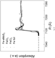
- the EXAFS Wavelet analysis was performed following the protocol and calculations developed by Marina Chukalina and Harald Funke, where the backscatter atoms are distinguished within the same atomic shell 16 . To confirm the reproducibility of the experimental data, at least 2 scan sets were collected and compared for each sample. The spectra were calibrated with Fe and Mo foil as reference. The amplitude reduction factor was obtained from analysis of the Fe and Mo foil, which was used as a fixed input parameter to allow refinement in the coordination number and bond distance of the absorption element.
- PMT photomultiplier tube
- ATR-FTIR Attenuated total reflection fourier transform infrared
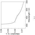
- UV-vis absorption spectroscopy Ultraviolet-visible (UV-vis) absorption spectroscopy. UV-vis absorption spectrum was collected using a Varian 100 Bio UV-Visible Spectrometer in absorbance mode with a step interval of 1 nm. The solution after reaction overnight was filtered. The obtained 5 mL was mixed with 5 mL of 0.14 M para-(dimethylamino) benzaldehyde and 1 M H 2 SO 4 solution, finally transferred into an optical glass cuvette for hydrazine measurement. The concentration of ammonia solution is also detected using UV-vis spectrum with Nessler's agent.
- DFT Theoretical Calculation. All calculations were performed using the first-principles density of functional theory (DFT) as implemented in Vienna ab initio simulation packages (VASP) 20 , the exchange-correlation energy functional described by generalized gradient approximation using Perdew-Burke-Ernzerhof (PBE) functional 21 , and the ion-electron interaction was treated using the projector-augmented wave (PAW) method 22 with a plane-wave cutoff energy of 400 eV. A (3 ⁇ 3) supercell of 2H-MoS 2 was selected to simulate single-layered MoS 2 (sMoS 2 ), periodic boundary conditions were employed and 15 ⁇ of vacuum in the z-direction was set to separate neighboring single-layered MoS 2 .
- DFT first-principles density of functional theory
- VASP Vienna ab initio simulation packages
- PBE Perdew-Burke-Ernzerhof
- PAW projector-augmented wave
- the Brillouin zone has been sampled using a 2 ⁇ 2 ⁇ 1 and an 8 ⁇ 8 ⁇ 4 Monkhorst-Pack 23 grid of k-points for geometry optimizations and orbital analysis calculations, respectively. Both lattice constants and atomic positions were relaxed until the forces on atoms were less than 0.02 eV ⁇ -1 and the total energy change was less than 1.0 ⁇ 10 5 eV. To rationalize the different performance of sMoS 2 and transition metal doped MoS 2 in catalytic ammonia photosynthesis, density of states and frontier orbitals topology analysis were performed at the PBE/PAW level of theory.
- Isotopic N 2 was used to prove that the obtained ammonia derives from N 2 gas rather than some other sources.
- Indophenol assays were prepared by adding 0.5 mL of aliquot solution after 1-h reaction to 0.1 mL of 1% phenolic solution in 95% ethanol/water. Stepwise, 0.375 mL of 1% NaClO in alkaline sodium citrate solution and 0.5 mL of 0.5% Na[Fe(CN) 5 NO] solution were added. The assayed aliquots were aged overnight before analyzing on a Xevo LCMS-ESI system.
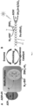
- the 2-D single molecular layer MoS 2 (termed sMoS 2 ) consisting of three-sub-layers of S-Mo-S in a trigonal prismatic 2-H structure was first synthesized via exfoliation of bulk MoS 2 using n-butyllithium. Subsequently Fe atoms were attached to sMoS 2 using a hydrothermal method for in-situ formed sulphide species ( Figs. 2 and 3 ), followed by H 2 reduction to afford the molecular Fe-sMoS 2 in nanosize. In this synthesis, Fe atoms were atomically dispersed and assembled onto the basal plane of sMoS 2 .
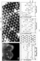
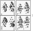
- Fig. 4A shows a typical high-angle annular dark-field scanning transmission electron microscopy (HAADF-STEM) image of Fe-sMoS 2 with corresponding 2-H characteristic pattern.
- HAADF-STEM high-angle annular dark-field scanning transmission electron microscopy
- Fig. 6B shows the WT-EXAFS wavelet transformed analysis based on Morlet wavelets, which can be used to differentiate closely-related spatial interactions 25 .
- the hot spot of the WT maximum at ⁇ 3 ⁇ -1 is well-resolved at the first coordination shell, which can clearly be related to the Fe-S bond at atop site.
- the WT intensity hot spot at ⁇ 8 ⁇ -1 region corresponding to the Fe-Fe bond was not detected in Fe-sMoS 2 , which indicates the sole dispersion of individual Fe atoms in Fe-sMoS 2 ( Fig. 8 ).
- X-ray absorption near-edge structure analysis was also carried out to better understand the single-atom Fe-sMoS 2 catalyst.
- XANES X-ray absorption near-edge structure
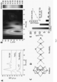
- Fig. 6E confirms that Fe-sMoS 2 with [Fe-S 2 -Mo] is active to convert N 2 to NH 3 via photo-activation to provide excited electrons for the N 2 fixation in H 2 O at ambient conditions.
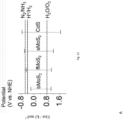
- Bulk MoS 2 is shown to be inert for N 2 reduction presumably because of its conduction band (CB) is more positive than that of the N 2 /NH 3 redox couple 27 (see Fig. 12 ).
- CB conduction band
- the activity for nitrogen fixation to ammonia is gradually enhanced. It has been proven that the band gap of MoS 2 could be enlarged with a more negative CB edge striding over the N 2 /NH 3 redox couple 27,28 .
- Fe-sMoS 2 with [Fe-S 2 -Mo] motifs on 2-D single layered MoS 2 show the highest ammonia production activity from direct visible light activation without using sacrificial reagent (see entries 1 and 2 in Table 3). This indicates its unique structure for the efficient charge separation and activation of N 2 in visible light and water for the ammonia production.
- Isotope labelled 15 N 2 was used to track the nitrogen source of ammonia, which confirmed that gaseous 15 N 2 was fixed by this FeMoco-like Fe-sMoS 2 ( Fig. 13 ).
- further activity promotion by incorporation of light-captured CdS quantum dots to Fe-sMoS 2 can be achieved.
- the rate for N 2 reduction to NH 3 maintains for at least 120 min under constant illumination without showing any obvious attenuation ( Fig 6E inset). It is expected that the CdS quantum dots can contribute additional electron-hole pairs from visible light illumination, the significant activity enhancement reflects their efficient charge separation by the [Fe-S 2 -Mo] motifs in Fe-sMoS 2 at the materials interface.
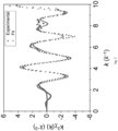
- the dynamic N 2 reduction to NH 3 over Fe-sMoS 2 was also studied using in-situ ATR-FTIR with light illumination ( Figs. 14A and 15 ).
- the IR absorption bands of 3303 and 1634 cm -1 shown in Fig. 14A can be attributed to the O-H stretching and H-O-H bending of adsorbed water molecules, respectively on the catalyst structure. Their decreasing signals from background as a result of the consumption of the adsorbed water molecules upon the light illumination in N 2 .
- the Fe-doped sMoS 2 with the Fe-S 2 -Mo motifs displays the best combination of metal site and 'electron relay' components for charge separation analogously to that in the biological system. Table 4.
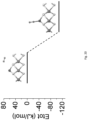
- N 2 For N 2 activation over nitrogenase, it was suggested from theoretical calculations that N 2 could linearly bind to either the molybdenum atom over the distal pathway (hydrogenation starts at terminal N), or the iron atom over the alternating pathway (hydrogenation starts at N in proximity to Fe) in the FeMoco 9 .
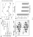
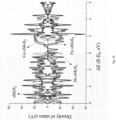
- the electron states of HOMO and LUMO and band structures in Mn, Fe, Co, and Ni-doped sMoS 2 were then modelled ( Figs. 14C , 18 , and 19 ).
- the HOMO and LUMO orbitals concentrate on the edge of sMoS 2 with relatively low electron delocalization, verifying the highly active edge site of s-MoS 2 as that reported in literature.
- Transition metal atom doped distinctly improves the degree of delocalization of the frontier orbitals, especially to their LUMO, the frontier orbitals delocalization follows the order: Fe > Co > Mn ⁇ Ni.
- the higher degree of delocalization indicate the more stable population of photo-excited electrons in LUMO orbitals, thus accounting the longer lifetime for the recombination of excited photo-generated electrons and photo-generated holes. This is in good agreement with the TRPL experimental results.
- the LUMO orbital distribution over the Fe atom in Fe doped sMoS 2 should be noted ( Fig. 14D ). Particularly, they demonstrate that excited electrons could be transferred from valence band to conduction band of sMoS 2 via the conductive Fe-S 2 -Mo motifs and resided on to the Fe atom during the photo-exciting process to enter to the anti-bonding orbital of absorbed N 2 molecule and thus facilitating the hydrogenation reaction of N 2 for ammonia production.
- the density of state calculation indicates a smaller band gap of Fe doping sMoS 2 relative to other catalyst materials, which is also favorable for electron transfer from HOMO to LUMO by photo-excitation.
- the intermediate species via the latter pathway is more stable compared with that via the former pathway. Based on the energy plots, the nitrogen fixation to ammonia over [Fe-S 2 -Mo] sites through the alternating pathway appears to be more energetically favoured despite the higher activation barrier in the first hydrogenation step.
- Quantum efficiency (Q.E.) for photon to hydrogen in ammonia is the key parameter to evaluate the conversion efficiency of renewable light energy.
- Fig. 14D shows that the Q.E. of this nitrogenase-mimic Fe-sMoS 2 can be up to 3.5% at 436 nm, which is believed to be the highest value reported in photo-ammonia synthesis.
- a bio-inspired solid structure consisting of nitrogenase-like [Fe-S 2 -Mo] four membered rings in 2D single layer of MoS 2 is for the first time synthesized.
- the material mimics the nitrogenase enzyme, which shows the strong ability to reduce N 2 to NH 3 in aqueous solution under mild conditions with visible light illumination where excited electrons from the sMoS 2 slab are conducted to the redox active Fe site through the [Fe-S 2 -Mo] as the electron relay units.
- Introduction of light-sensitive CdS quantum dots can further boost the NH 3 harvest.
- the [Fe-S 2 -Mo] motif is clearly shown to carry out an associative mechanism in converting N 2 to NH 3 .
- N 2 prefers to bind linearly on the Fe atom in the [Fe-S 2 -Mo], which will undergo stepwise hydrogenations to NH 3 with the successive formation of hydrogen atom from H + /e - pairs.
- the photocatalytic method for ammonia synthesis over this type of materials although small in quantity may open up an exciting possibility for the decentralization of ammonia supply for fertilizer to local farmlands.
Landscapes
- Chemical & Material Sciences (AREA)
- Organic Chemistry (AREA)
- Engineering & Computer Science (AREA)
- Chemical Kinetics & Catalysis (AREA)
- Materials Engineering (AREA)
- Physics & Mathematics (AREA)
- Inorganic Chemistry (AREA)
- Analytical Chemistry (AREA)
- Plasma & Fusion (AREA)
- Optics & Photonics (AREA)
- Health & Medical Sciences (AREA)
- Toxicology (AREA)
- Catalysts (AREA)
Claims (14)
- Photokatalysator, umfassend:ein geschichtetes Basismaterial, das 1 bis 100 Schichten umfasst, wobei das geschichtete Basismaterial ausgewählt ist aus der Gruppe bestehend aus Molybdändisulfid, Wolframdisulfid, Molybdäntellurid, Wolframtellurid, Molybdänselenid und Wolframselenid; und0,1-10,0 Gew.-%, relativ zu dem Gewicht des Basismaterials, von einem oder mehreren Übergangsmetallen der Gruppe VI, VII, VIII, IX oder X, wobei das eine oder die mehreren Übergangsmetalle der Gruppe VI, VII, VIII, IX oder X ausgewählt sind aus der Gruppe bestehend aus Fe, Mn, Co, Ni, Ru, Rh, Pd und Pt,wobei der Photokatalysator ferner 0,1-50,0 Gew.-%, relativ zu dem Gewicht des Basismaterials, von einem oder mehreren Halbleitermaterialien mit einer durchschnittlichen Partikelgröße von 0,5-50,0 nm umfasst.
- Photokatalysator nach Anspruch 1, wobei eine oder beide der folgenden Aussagen (A) und (B) zutreffen:(A) das geschichtete Basismaterial umfasst 1 und 10 Schichten;(B) das geschichtete Basismaterial ist Molybdändisulfid.
- Photokatalysator nach Anspruch 1 oder 2, wobei der Photokatalysator 1,0-3,0 Gew.-%, relativ zu dem Gewicht des Basismaterials, von dem einen oder den mehreren Übergangsmetallen der Gruppe VI, VII, VIII, IX oder X umfasst.
- Photokatalysator nach Anspruch 1, 2 oder 3, wobei das eine oder die mehreren Übergangsmetalle der Gruppe VI, VII, VIII, IX oder X Fe sind.
- Photokatalysator nach einem vorhergehenden Anspruch, wobei die Größe des einen oder der mehreren Übergangsmetalle der Gruppe VI, VII, VIII, IX oder X von einzelnen Atomen der Übergangsmetalle zu Atomclustern der Übergangsmetalle mit einem maximalen Durchmesser von 4,0 nm reicht.
- Photokatalysator nach einem vorhergehenden Anspruch, wobei eine oder mehrere der folgenden Aussagen (A) und (C) zutreffen:(A) das eine oder die mehreren Halbleitermaterialien weisen eine durchschnittliche Partikelgröße von 0,5-15,0 nm auf;(B) das eine oder die mehreren Halbleitermaterialien weisen die Zusammensetzungsformel ABxC1-x auf, wobeiA ausgewählt ist aus der Gruppe bestehend aus Cd, Pb und In;B und C ausgewählt sind aus der Gruppe bestehend aus S, Se, Te, As und P; undx eine Zahl ist, die von 0,01 bis 1 reicht;(C) das eine oder die mehreren Halbleitermaterialien sind Cadmiumsulfid.
- Photokatalysator nach einem vorhergehenden Anspruch, wobei der Photokatalysator eine durchschnittliche Partikelgröße von 0,05-100 µm aufweist.
- Verfahren zur Herstellung eines Photokatalysators nach einem vorhergehenden Anspruch, wobei das Verfahren die folgenden Schritte umfasst:a) Bereitstellen einer Dispersion eines geschichteten Basismaterials, das 1 bis 100 Schichten umfasst, wobei das geschichtete Basismaterial ausgewählt ist aus der Gruppe bestehend aus Molybdändisulfid, Wolframdisulfid, Molybdäntellurid, Wolframtellurid, Molybdänselenid und Wolframselenid; undb) Kontaktieren der Dispersion des geschichteten Basismaterials mit einer Lösung von einem oder mehreren Übergangsmetallen der Gruppe VI, VII, VIII, IX oder X, wobei das eine oder die mehreren Übergangsmetalle der Gruppe VI, VII, VIII, IX oder X ausgewählt sind aus der Gruppe bestehend aus Fe, Mn, Co, Ni, Ru, Rh, Pd und Pt,wobei der aus Schritt b) resultierende Photokatalysator mit einer wässrigen Lösung von einem oder mehreren Halbleitermaterialien mit einer durchschnittlichen Partikelgröße von 0,5-50,0 nm kontaktiert wird.
- Verfahren nach Anspruch 8, wobei das geschichtete Basismaterial mit zwischen 1 und 100 Schichten durch Abblättern des Basismaterials in seiner Massenform hergestellt wird, wobei optional das Basismaterial in seiner Massenform durch Folgendes abgeblättert wird:(i) Kontaktieren einer wässrigen Mischung des Basismaterials in seiner Massenform mit einem Interkalationsmittel;(ii) Beschallen der aus Schritt (i) resultierenden Mischung; und(iii) Isolieren des aus Schritt (ii) resultierenden geschichteten Basismaterials mit zwischen 1 und 100 Schichten.
- Verfahren nach Anspruch 8 oder 9, wobei die Lösung von einem oder mehreren Übergangsmetallen der Gruppe VI, VII, VIII, IX oder X durch Auflösen von einer oder mehreren Übergangsmetallvorläuferverbindungen der Gruppe VI, VII, VIII, IX oder X in einem Lösungsmittel hergestellt wird.
- Verfahren nach einem der Ansprüche 8, 9 oder 10, wobei Schritt b) bei einer Temperatur von 10-325 °C, optional unter hydrothermalen Bedingungen, durchgeführt wird.
- Verfahren nach Anspruch 11, wobei Schritt b) bei einer Temperatur von 130-190 °C unter hydrothermalen Bedingungen durchgeführt wird.
- Photokatalytisches Verfahren zur Umwandlung von molekularem Stickstoff in Ammoniak, wobei das Verfahren den folgenden Schritt umfasst:a) Kontaktieren von molekularem Stickstoff mit einem Photokatalysator nach einem der Ansprüche 1-7 in der Gegenwart von Wasser;wobei Schritt a) unter der Anwendung von elektromagnetischer Strahlung mit einer Wellenlänge von 270-1000 nm ausgeführt wird.
- Verfahren nach Anspruch 13, wobei eine oder mehrere der folgenden Aussagen (A)-(D) zutreffen:(A) die elektromagnetische Strahlung wird der Mischung aus Schritt a) unter Verwendung eines Solarkonzentrators zugeführt;(B) Schritt a) wird bei einer Temperatur von 5-270 °C durchgeführt, wobei optional Schritt a) bei einer Temperatur von 10-50 °C durchgeführt wird;(C) der Photokatalysator ist bereitgestellt als:A) ein Festbett;B) eine Suspension; oderC) ein Dünnfilm;(D) Schritt a) wird ausgeführt als:A) ein Batch-Verfahren; oderB) ein kontinuierliches Verfahren.
Applications Claiming Priority (2)
| Application Number | Priority Date | Filing Date | Title |
|---|---|---|---|
| GBGB1904004.7A GB201904004D0 (en) | 2019-03-22 | 2019-03-22 | Photocatalyst |
| PCT/GB2020/050715 WO2020193951A1 (en) | 2019-03-22 | 2020-03-18 | Photocatalyst |
Publications (3)
| Publication Number | Publication Date |
|---|---|
| EP3941622A1 EP3941622A1 (de) | 2022-01-26 |
| EP3941622C0 EP3941622C0 (de) | 2024-11-06 |
| EP3941622B1 true EP3941622B1 (de) | 2024-11-06 |
Family
ID=66381302
Family Applications (1)
| Application Number | Title | Priority Date | Filing Date |
|---|---|---|---|
| EP20715171.3A Active EP3941622B1 (de) | 2019-03-22 | 2020-03-18 | Photokatalysator |
Country Status (4)
| Country | Link |
|---|---|
| US (1) | US12121885B2 (de) |
| EP (1) | EP3941622B1 (de) |
| GB (1) | GB201904004D0 (de) |
| WO (1) | WO2020193951A1 (de) |
Families Citing this family (9)
| Publication number | Priority date | Publication date | Assignee | Title |
|---|---|---|---|---|
| CN111167521B (zh) * | 2020-01-18 | 2023-02-17 | 河南师范大学 | 催化材料及其制备方法、光催化剂、电催化剂 |
| CN112844420A (zh) * | 2021-01-11 | 2021-05-28 | 湖南大学 | 一种过渡金属掺杂富缺陷的二硫化钼及其制备方法和应用 |
| CN113281318B (zh) * | 2021-05-26 | 2022-06-14 | 四川中科微纳科技有限公司 | MoSe2@Fe纳米复合材料荧光-比色双信号检测Fe3+和GSH |
| CN113318755A (zh) * | 2021-06-23 | 2021-08-31 | 淮北师范大学 | 一种有机无机杂化MnxCd1-xS固溶体光催化剂的制备方法 |
| CN115007177B (zh) * | 2022-06-17 | 2023-06-23 | 四川大学 | 一种CdSeS幻数纳米团簇及其作为光催化剂的用途 |
| CN115931749B (zh) * | 2022-11-23 | 2025-04-04 | 武汉中地西能科技有限公司 | 一种钼基金属有机骨架用于检测阿特拉津含量的方法及试剂盒 |
| CN116713012A (zh) * | 2023-05-31 | 2023-09-08 | 天津城建大学 | 一种铁掺杂氯氧化铋可见光催化材料的制备方法 |
| CN118767988B (zh) * | 2024-06-14 | 2025-05-02 | 华南师范大学 | 一种钼钨杂化多酸簇材料及其制备方法和应用、1,5-二酮衍生物的制备方法 |
| CN120861106A (zh) * | 2025-09-25 | 2025-10-31 | 洛阳理工学院 | 一种含有氧空位的Ag/WS2/BiOI纳米光催化材料及制备方法 |
Family Cites Families (14)
| Publication number | Priority date | Publication date | Assignee | Title |
|---|---|---|---|---|
| CA2404830C (en) | 2002-10-17 | 2011-03-22 | University Of Windsor | Metallic mesoporous transition metal oxide molecular sieves, room temperature activation of dinitrogen and ammonia production |
| JP5373410B2 (ja) | 2009-01-09 | 2013-12-18 | トヨタ自動車株式会社 | アンモニア合成方法 |
| JP5604204B2 (ja) | 2010-07-21 | 2014-10-08 | 日立造船株式会社 | アンモニアの合成方法 |
| US9873115B2 (en) * | 2013-07-01 | 2018-01-23 | The Regents Of The University Of Colorado, A Body Corporate | Nanostructured photocatalysts and doped wide-bandgap semiconductors |
| CN104338547B (zh) * | 2013-07-29 | 2016-08-31 | 中国科学院理化技术研究所 | 基于量子点/棒和二硫化钼纳米片的光催化剂、制备方法、光催化体系及其重整生物质制氢的方法 |
| CN103440997B (zh) | 2013-08-26 | 2016-06-29 | 中国科学技术大学 | 金属双氢氧化物/二硫化钼纳米复合材料及其制备方法和应用 |
| JP2015120118A (ja) | 2013-12-24 | 2015-07-02 | 株式会社デンソー | アンモニア合成触媒 |
| CN104525938B (zh) | 2014-12-23 | 2017-02-22 | 国家纳米科学中心 | 一种二硫化钼/金纳米棒复合材料、制备方法及用途 |
| CN104630811B (zh) | 2015-02-13 | 2017-03-08 | 王海斌 | 一种电解制氨装置 |
| CN106964372B (zh) * | 2017-04-16 | 2019-04-19 | 合肥国轩高科动力能源有限公司 | 一种金属纳米颗粒非对称性单面镶嵌二硫化钼纳米片的合成方法 |
| CN107262117B (zh) * | 2017-07-25 | 2020-06-19 | 华中师范大学 | 单原子金属掺杂少层二硫化钼电催化材料、合成及其电催化固氮的方法 |
| CN108855149A (zh) * | 2018-06-12 | 2018-11-23 | 湖北文理学院 | 复合光催化剂及其制备方法 |
| US12031220B2 (en) * | 2018-06-28 | 2024-07-09 | Monash University | Electrolytic composition and cathode for the nitrogen reduction reaction |
| WO2020000055A1 (en) | 2018-06-28 | 2020-01-02 | Mole Patrol Holdings Pty Ltd | A device and a method for imaging a tissue area |
-
2019
- 2019-03-22 GB GBGB1904004.7A patent/GB201904004D0/en not_active Ceased
-
2020
- 2020-03-18 EP EP20715171.3A patent/EP3941622B1/de active Active
- 2020-03-18 WO PCT/GB2020/050715 patent/WO2020193951A1/en not_active Ceased
- 2020-03-18 US US17/441,315 patent/US12121885B2/en active Active
Also Published As
| Publication number | Publication date |
|---|---|
| EP3941622C0 (de) | 2024-11-06 |
| GB201904004D0 (en) | 2019-05-08 |
| US20220161247A1 (en) | 2022-05-26 |
| US12121885B2 (en) | 2024-10-22 |
| EP3941622A1 (de) | 2022-01-26 |
| WO2020193951A1 (en) | 2020-10-01 |
Similar Documents
| Publication | Publication Date | Title |
|---|---|---|
| EP3941622B1 (de) | Photokatalysator | |
| Xia et al. | Single-atom photocatalysts for emerging reactions | |
| Xue et al. | Single-atom catalysts for photocatalytic energy conversion | |
| Sun et al. | Recent progress in research and design concepts for the characterization, testing, and photocatalysts for nitrogen reduction reaction | |
| Behera et al. | Challenges and prospects in the selective photoreduction of CO 2 to C1 and C2 products with nanostructured materials: A review | |
| Ithisuphalap et al. | Photocatalysis and photoelectrocatalysis methods of nitrogen reduction for sustainable ammonia synthesis | |
| Melchionna et al. | Updates on the Roadmap for Photocatalysis | |
| Paul et al. | Progress of electrocatalytic urea synthesis: strategic design, reactor engineering, mechanistic details and techno-commercial study | |
| EP2636641B1 (de) | Herstellung eines halbleiterphotokatalysators zur photokatalytischen reformierung von biomassederivaten zur wasserstofferzeugung | |
| Nethravathi et al. | Silver-doped ZnO embedded reduced graphene oxide hybrid nanostructured composites for superior photocatalytic hydrogen generation, dye degradation, nitrite sensing and antioxidant activities | |
| Zhang et al. | Atomically precise dinuclear Ni2 active site-modified MOF-derived ZnO@ NC heterojunction toward high-performance N2 photofixation | |
| Tang et al. | Single-metal catalytic sites via high-throughput mechanochemistry enable selective and efficient CO2 photoreduction | |
| Wang et al. | Recent advances and challenges in efficient selective photocatalytic CO2 methanation | |
| Zhang et al. | A review on electrocatalytic CO2 conversion via C–C and C–N coupling | |
| Mousavi-Salehi et al. | Gold supported on graphene oxide/silica photocatalyst for hydrogen generation from formic acid | |
| Cui et al. | Pivotal Impact Factors in Photocatalytic Reduction of CO2 to Value‐Added C1 and C2 Products | |
| Kong et al. | Atomically dispersed metal cocatalysts for solar energy conversion | |
| Xia et al. | Pd single-atom and S-scheme heterojunction synergy in improving charge transport for high performance photocatalyzed hydrogen evolution reaction | |
| Yuan et al. | Facet-dependent spatial separation of dual cocatalysts on MOF photocatalysts for H2O2 production coupling biomass oxidation with enhanced performance | |
| Hui et al. | Recent progress of photocatalysts based on tungsten and related metals for nitrogen reduction to ammonia | |
| Yuan et al. | Light-induced CoOX surface reconstruction in hollow heterostructure for durable photocatalytic seawater splitting | |
| Zhang et al. | Stable Ti3+ Sites Derived from the Ti x O y-P z Layer Boost Cubic Fe2O3 for Enhanced Photocatalytic N2 Reduction | |
| Anadebe et al. | Carbon dots in catalysis: CO2 conversion, H2 evolution, and organic reactions | |
| Yang et al. | Advancements and prospects of near-infrared-light driven CO 2 reduction reaction | |
| Rojas et al. | Photocatalytic oxidation of glycerol using x/TiO2 (with x= Cu, Ag, and Cu-Ag) to dihydroxyacetone and other value-added products |
Legal Events
| Date | Code | Title | Description |
|---|---|---|---|
| STAA | Information on the status of an ep patent application or granted ep patent |
Free format text: STATUS: UNKNOWN |
|
| STAA | Information on the status of an ep patent application or granted ep patent |
Free format text: STATUS: THE INTERNATIONAL PUBLICATION HAS BEEN MADE |
|
| PUAI | Public reference made under article 153(3) epc to a published international application that has entered the european phase |
Free format text: ORIGINAL CODE: 0009012 |
|
| STAA | Information on the status of an ep patent application or granted ep patent |
Free format text: STATUS: REQUEST FOR EXAMINATION WAS MADE |
|
| 17P | Request for examination filed |
Effective date: 20210813 |
|
| AK | Designated contracting states |
Kind code of ref document: A1 Designated state(s): AL AT BE BG CH CY CZ DE DK EE ES FI FR GB GR HR HU IE IS IT LI LT LU LV MC MK MT NL NO PL PT RO RS SE SI SK SM TR |
|
| DAV | Request for validation of the european patent (deleted) | ||
| DAX | Request for extension of the european patent (deleted) | ||
| STAA | Information on the status of an ep patent application or granted ep patent |
Free format text: STATUS: EXAMINATION IS IN PROGRESS |
|
| 17Q | First examination report despatched |
Effective date: 20240122 |
|
| REG | Reference to a national code |
Ref country code: DE Ref legal event code: R079 Free format text: PREVIOUS MAIN CLASS: B01J0035000000 Ipc: B01J0023280000 Ref country code: DE Ref legal event code: R079 Ref document number: 602020040782 Country of ref document: DE Free format text: PREVIOUS MAIN CLASS: B01J0035000000 Ipc: B01J0023280000 |
|
| GRAP | Despatch of communication of intention to grant a patent |
Free format text: ORIGINAL CODE: EPIDOSNIGR1 |
|
| STAA | Information on the status of an ep patent application or granted ep patent |
Free format text: STATUS: GRANT OF PATENT IS INTENDED |
|
| RIC1 | Information provided on ipc code assigned before grant |
Ipc: C01C 1/04 20060101ALI20240516BHEP Ipc: B01J 35/50 20240101ALI20240516BHEP Ipc: B01J 35/40 20240101ALI20240516BHEP Ipc: B01J 35/39 20240101ALI20240516BHEP Ipc: B01J 35/30 20240101ALI20240516BHEP Ipc: B01J 35/00 20060101ALI20240516BHEP Ipc: B01J 27/051 20060101ALI20240516BHEP Ipc: B01J 37/34 20060101ALI20240516BHEP Ipc: B01J 37/02 20060101ALI20240516BHEP Ipc: C01C 1/02 20060101ALI20240516BHEP Ipc: B01J 23/652 20060101ALI20240516BHEP Ipc: B01J 23/85 20060101ALI20240516BHEP Ipc: B01J 27/057 20060101ALI20240516BHEP Ipc: B01J 27/047 20060101ALI20240516BHEP Ipc: B01J 23/30 20060101ALI20240516BHEP Ipc: B01J 23/28 20060101AFI20240516BHEP |
|
| INTG | Intention to grant announced |
Effective date: 20240607 |
|
| GRAS | Grant fee paid |
Free format text: ORIGINAL CODE: EPIDOSNIGR3 |
|
| GRAA | (expected) grant |
Free format text: ORIGINAL CODE: 0009210 |
|
| STAA | Information on the status of an ep patent application or granted ep patent |
Free format text: STATUS: THE PATENT HAS BEEN GRANTED |
|
| AK | Designated contracting states |
Kind code of ref document: B1 Designated state(s): AL AT BE BG CH CY CZ DE DK EE ES FI FR GB GR HR HU IE IS IT LI LT LU LV MC MK MT NL NO PL PT RO RS SE SI SK SM TR |
|
| REG | Reference to a national code |
Ref country code: GB Ref legal event code: FG4D |
|
| REG | Reference to a national code |
Ref country code: CH Ref legal event code: EP |
|
| REG | Reference to a national code |
Ref country code: DE Ref legal event code: R096 Ref document number: 602020040782 Country of ref document: DE |
|
| REG | Reference to a national code |
Ref country code: IE Ref legal event code: FG4D |
|
| U01 | Request for unitary effect filed |
Effective date: 20241205 |
|
| U07 | Unitary effect registered |
Designated state(s): AT BE BG DE DK EE FI FR IT LT LU LV MT NL PT RO SE SI Effective date: 20241216 |
|
| PG25 | Lapsed in a contracting state [announced via postgrant information from national office to epo] |
Ref country code: HR Free format text: LAPSE BECAUSE OF FAILURE TO SUBMIT A TRANSLATION OF THE DESCRIPTION OR TO PAY THE FEE WITHIN THE PRESCRIBED TIME-LIMIT Effective date: 20241106 Ref country code: IS Free format text: LAPSE BECAUSE OF FAILURE TO SUBMIT A TRANSLATION OF THE DESCRIPTION OR TO PAY THE FEE WITHIN THE PRESCRIBED TIME-LIMIT Effective date: 20250306 |
|
| PG25 | Lapsed in a contracting state [announced via postgrant information from national office to epo] |
Ref country code: ES Free format text: LAPSE BECAUSE OF FAILURE TO SUBMIT A TRANSLATION OF THE DESCRIPTION OR TO PAY THE FEE WITHIN THE PRESCRIBED TIME-LIMIT Effective date: 20241106 |
|
| PG25 | Lapsed in a contracting state [announced via postgrant information from national office to epo] |
Ref country code: NO Free format text: LAPSE BECAUSE OF FAILURE TO SUBMIT A TRANSLATION OF THE DESCRIPTION OR TO PAY THE FEE WITHIN THE PRESCRIBED TIME-LIMIT Effective date: 20250206 |
|
| PG25 | Lapsed in a contracting state [announced via postgrant information from national office to epo] |
Ref country code: GR Free format text: LAPSE BECAUSE OF FAILURE TO SUBMIT A TRANSLATION OF THE DESCRIPTION OR TO PAY THE FEE WITHIN THE PRESCRIBED TIME-LIMIT Effective date: 20250207 |
|
| PG25 | Lapsed in a contracting state [announced via postgrant information from national office to epo] |
Ref country code: PL Free format text: LAPSE BECAUSE OF FAILURE TO SUBMIT A TRANSLATION OF THE DESCRIPTION OR TO PAY THE FEE WITHIN THE PRESCRIBED TIME-LIMIT Effective date: 20241106 |
|
| PG25 | Lapsed in a contracting state [announced via postgrant information from national office to epo] |
Ref country code: RS Free format text: LAPSE BECAUSE OF FAILURE TO SUBMIT A TRANSLATION OF THE DESCRIPTION OR TO PAY THE FEE WITHIN THE PRESCRIBED TIME-LIMIT Effective date: 20250206 |
|
| U20 | Renewal fee for the european patent with unitary effect paid |
Year of fee payment: 6 Effective date: 20250324 |
|
| PG25 | Lapsed in a contracting state [announced via postgrant information from national office to epo] |
Ref country code: SM Free format text: LAPSE BECAUSE OF FAILURE TO SUBMIT A TRANSLATION OF THE DESCRIPTION OR TO PAY THE FEE WITHIN THE PRESCRIBED TIME-LIMIT Effective date: 20241106 |
|
| PG25 | Lapsed in a contracting state [announced via postgrant information from national office to epo] |
Ref country code: SK Free format text: LAPSE BECAUSE OF FAILURE TO SUBMIT A TRANSLATION OF THE DESCRIPTION OR TO PAY THE FEE WITHIN THE PRESCRIBED TIME-LIMIT Effective date: 20241106 |
|
| PG25 | Lapsed in a contracting state [announced via postgrant information from national office to epo] |
Ref country code: CZ Free format text: LAPSE BECAUSE OF FAILURE TO SUBMIT A TRANSLATION OF THE DESCRIPTION OR TO PAY THE FEE WITHIN THE PRESCRIBED TIME-LIMIT Effective date: 20241106 |
|
| PLBE | No opposition filed within time limit |
Free format text: ORIGINAL CODE: 0009261 |
|
| STAA | Information on the status of an ep patent application or granted ep patent |
Free format text: STATUS: NO OPPOSITION FILED WITHIN TIME LIMIT |
|
| PG25 | Lapsed in a contracting state [announced via postgrant information from national office to epo] |
Ref country code: MC Free format text: LAPSE BECAUSE OF FAILURE TO SUBMIT A TRANSLATION OF THE DESCRIPTION OR TO PAY THE FEE WITHIN THE PRESCRIBED TIME-LIMIT Effective date: 20241106 |
|
| 26N | No opposition filed |
Effective date: 20250807 |
|
| REG | Reference to a national code |
Ref country code: CH Ref legal event code: H13 Free format text: ST27 STATUS EVENT CODE: U-0-0-H10-H13 (AS PROVIDED BY THE NATIONAL OFFICE) Effective date: 20251024 |
|
| GBPC | Gb: european patent ceased through non-payment of renewal fee |
Effective date: 20250318 |