EP3940924B1 - Rotor eines motors, verfahren zur wartung des rotors eines motors, motor und elektrische windkraftanlage - Google Patents
Rotor eines motors, verfahren zur wartung des rotors eines motors, motor und elektrische windkraftanlage Download PDFInfo
- Publication number
- EP3940924B1 EP3940924B1 EP20787468.6A EP20787468A EP3940924B1 EP 3940924 B1 EP3940924 B1 EP 3940924B1 EP 20787468 A EP20787468 A EP 20787468A EP 3940924 B1 EP3940924 B1 EP 3940924B1
- Authority
- EP
- European Patent Office
- Prior art keywords
- rotor
- connection
- segments
- motor
- magnetic yoke
- Prior art date
- Legal status (The legal status is an assumption and is not a legal conclusion. Google has not performed a legal analysis and makes no representation as to the accuracy of the status listed.)
- Active
Links
- 238000000034 method Methods 0.000 title claims description 21
- 230000002950 deficient Effects 0.000 claims description 16
- 230000000149 penetrating effect Effects 0.000 claims description 8
- 239000000565 sealant Substances 0.000 claims description 7
- 238000012423 maintenance Methods 0.000 description 10
- 230000008569 process Effects 0.000 description 10
- 238000007789 sealing Methods 0.000 description 7
- 230000000712 assembly Effects 0.000 description 3
- 238000000429 assembly Methods 0.000 description 3
- 230000008878 coupling Effects 0.000 description 3
- 238000010168 coupling process Methods 0.000 description 3
- 238000005859 coupling reaction Methods 0.000 description 3
- 238000001514 detection method Methods 0.000 description 3
- 230000005611 electricity Effects 0.000 description 3
- 230000008439 repair process Effects 0.000 description 3
- 238000004804 winding Methods 0.000 description 3
- 238000012986 modification Methods 0.000 description 2
- 230000004048 modification Effects 0.000 description 2
- 238000010248 power generation Methods 0.000 description 2
- 238000003466 welding Methods 0.000 description 2
- 241000239290 Araneae Species 0.000 description 1
- XEEYBQQBJWHFJM-UHFFFAOYSA-N Iron Chemical group [Fe] XEEYBQQBJWHFJM-UHFFFAOYSA-N 0.000 description 1
- 238000004378 air conditioning Methods 0.000 description 1
- 230000005540 biological transmission Effects 0.000 description 1
- 230000000694 effects Effects 0.000 description 1
- 239000012535 impurity Substances 0.000 description 1
- 238000009434 installation Methods 0.000 description 1
- 238000004519 manufacturing process Methods 0.000 description 1
- 239000000463 material Substances 0.000 description 1
- 238000013008 moisture curing Methods 0.000 description 1
- 230000001681 protective effect Effects 0.000 description 1
- 238000003860 storage Methods 0.000 description 1
Images


Classifications
-
- H—ELECTRICITY
- H02—GENERATION; CONVERSION OR DISTRIBUTION OF ELECTRIC POWER
- H02K—DYNAMO-ELECTRIC MACHINES
- H02K1/00—Details of the magnetic circuit
- H02K1/06—Details of the magnetic circuit characterised by the shape, form or construction
- H02K1/22—Rotating parts of the magnetic circuit
- H02K1/27—Rotor cores with permanent magnets
- H02K1/2786—Outer rotors
- H02K1/2787—Outer rotors the magnetisation axis of the magnets being perpendicular to the rotor axis
- H02K1/2789—Outer rotors the magnetisation axis of the magnets being perpendicular to the rotor axis the rotor consisting of two or more circumferentially positioned magnets
- H02K1/2791—Surface mounted magnets; Inset magnets
-
- H—ELECTRICITY
- H02—GENERATION; CONVERSION OR DISTRIBUTION OF ELECTRIC POWER
- H02K—DYNAMO-ELECTRIC MACHINES
- H02K1/00—Details of the magnetic circuit
- H02K1/06—Details of the magnetic circuit characterised by the shape, form or construction
- H02K1/22—Rotating parts of the magnetic circuit
- H02K1/28—Means for mounting or fastening rotating magnetic parts on to, or to, the rotor structures
- H02K1/30—Means for mounting or fastening rotating magnetic parts on to, or to, the rotor structures using intermediate parts, e.g. spiders
-
- H—ELECTRICITY
- H02—GENERATION; CONVERSION OR DISTRIBUTION OF ELECTRIC POWER
- H02K—DYNAMO-ELECTRIC MACHINES
- H02K7/00—Arrangements for handling mechanical energy structurally associated with dynamo-electric machines, e.g. structural association with mechanical driving motors or auxiliary dynamo-electric machines
- H02K7/14—Structural association with mechanical loads, e.g. with hand-held machine tools or fans
-
- H—ELECTRICITY
- H02—GENERATION; CONVERSION OR DISTRIBUTION OF ELECTRIC POWER
- H02K—DYNAMO-ELECTRIC MACHINES
- H02K15/00—Methods or apparatus specially adapted for manufacturing, assembling, maintaining or repairing of dynamo-electric machines
- H02K15/0006—Disassembling, repairing or modifying dynamo-electric machines
-
- H—ELECTRICITY
- H02—GENERATION; CONVERSION OR DISTRIBUTION OF ELECTRIC POWER
- H02K—DYNAMO-ELECTRIC MACHINES
- H02K2213/00—Specific aspects, not otherwise provided for and not covered by codes H02K2201/00 - H02K2211/00
- H02K2213/12—Machines characterised by the modularity of some components
-
- H—ELECTRICITY
- H02—GENERATION; CONVERSION OR DISTRIBUTION OF ELECTRIC POWER
- H02K—DYNAMO-ELECTRIC MACHINES
- H02K7/00—Arrangements for handling mechanical energy structurally associated with dynamo-electric machines, e.g. structural association with mechanical driving motors or auxiliary dynamo-electric machines
- H02K7/18—Structural association of electric generators with mechanical driving motors, e.g. with turbines
- H02K7/1807—Rotary generators
- H02K7/1823—Rotary generators structurally associated with turbines or similar engines
- H02K7/183—Rotary generators structurally associated with turbines or similar engines wherein the turbine is a wind turbine
- H02K7/1838—Generators mounted in a nacelle or similar structure of a horizontal axis wind turbine
-
- Y—GENERAL TAGGING OF NEW TECHNOLOGICAL DEVELOPMENTS; GENERAL TAGGING OF CROSS-SECTIONAL TECHNOLOGIES SPANNING OVER SEVERAL SECTIONS OF THE IPC; TECHNICAL SUBJECTS COVERED BY FORMER USPC CROSS-REFERENCE ART COLLECTIONS [XRACs] AND DIGESTS
- Y02—TECHNOLOGIES OR APPLICATIONS FOR MITIGATION OR ADAPTATION AGAINST CLIMATE CHANGE
- Y02E—REDUCTION OF GREENHOUSE GAS [GHG] EMISSIONS, RELATED TO ENERGY GENERATION, TRANSMISSION OR DISTRIBUTION
- Y02E10/00—Energy generation through renewable energy sources
- Y02E10/70—Wind energy
- Y02E10/72—Wind turbines with rotation axis in wind direction
Definitions
- the present disclosure relates to a technical filed of motors, and particularly relates to a rotor of a motor, a method for maintaining the rotor of the motor, the motor and a wind-power electric generator set.
- a direct-driven permanent-magnet wind-power electric generator is a motor that is directly connected to an impeller to drive. Since there is no gearbox, compared with a double-feed wind power electric generator, the direct-driven permanent-magnet wind-power electric generator has many advantages, such as a high power generation efficiency, a low noise, a high reliability and a low operation and maintenance cost etc.
- a speed of the direct-driven permanent-magnet wind-power electric generator is typically very low, in order to increase a power generation efficiency, it has to increase a volume of the motor. Therefore, in the case that a level of a power of the wind-power electric generator is very high, a diameter of the direct-driven permanent-magnet wind-power electric generator has to be increased, result in increasing the difficulty and the cost of transportation of the motor.
- the GB2505475A provides a segment for supporting electromagnetic coupling elements of a stator or rotor.
- the rotor comprises a plurality of rotor spokes such as rotor spokes, a rotor rim and a rotor hub.
- the rotor rim comprises a plurality of rotor rings axially spaced apart from each other.
- the rotor rings can, for example, be thought of as rotor supporting rings.
- the rotor rim comprises a first rotor ring, a second rotor ring, a third rotor ring and a fourth rotor ring.
- JP6498315B2 provides a rotor, a motor, an air-conditioning apparatus, and a method for manufacturing a rotor.
- the rotor includes a shaft, an inner core, an outer core and a coupling member.
- the outer core has radially outer parts of the divided cores brought into close contact with each other.
- JPS5671455A provides a rotor for rotary electric machine.
- the rotor includes a frame 32 of the rotor spider having a side plate 24, a coupling plate 25 and a supporting member 26, etc.
- the rotor can be divided into a plurality of segments, the divided segments are transported, and the segments are then welded at the field so that the integral rotor is formed thereat.
- a rotor of a motor, a method for maintaining the rotor of the motor, the motor and a wind-power electric generator set are provided by the present disclosure to improve a transportation convenience of the rotor of the motor.
- a rotor of a motor including a magnetic yoke, in which the magnetic yoke is in a cylindrical-like shape, and the magnetic yoke is configured to fix a magnet on its circumference surface; and a rotor support, including a shaft connection unit and a supporting ring, in which the shaft connection unit is coaxially connectable to a rotation shaft of the motor, the supporting ring is arranged on an outer periphery of the shaft connection unit, and the magnetic yoke is arranged to be coaxially connected to the supporting ring; wherein the supporting ring has the structure divided into the plurality of segments in the circumference direction of itself, the supporting ring comprises a plurality of supporting plates, the plurality of the supporting plates are successively spliced into an annular sheet-like body in the circumference direction, each supporting plate is provided with a first connection portion, the shaft connection unit is provided at its outer periphery with a second connection portion, and the plurality of
- the supporting plate extends in an arc-like direction, and has two opposite ends in the extending arc-like direction, the first connection portion is located between the two ends of the supporting plate.
- the supporting plate extends in an arc-like direction, and has two opposite ends in the extending arc-like direction, the first connection portions are arranged at two ends of each the supporting plate; herein two first connection portions of two adjacent supporting plates at a same splicing position are correspondingly connected to one second connection portion of the shaft connection unit.
- the rotor of the motor further includes an end plate, herein the end plate is in a ring-like shape and arranged coaxially with and spaced apart from the supporting ring, the supporting ring and the end plate are respectively arranged at two ends of the magnetic yoke in an axial direction.
- the supporting ring has the structure divided into the plurality of segments in the circumference direction of itself, the supporting ring includes a plurality of supporting plates, the plurality of the supporting plates are successively spliced into an annular sheet-like body in the circumference direction, the adjacent supporting plates are connected by a connection assembly; the adjacent supporting plates or the shaft connection unit and the supporting ring form a first pin hole at a splicing position; and/or the magnetic yoke has the structure divided into the plurality of segments in the circumference direction of itself, the magnetic yoke includes a plurality of magnetic yoke segments, the plurality of magnetic yoke segments are successively spliced into a cylindrical-like body in the circumference direction, the adjacent magnetic yoke segments are connected by a connection assembly, the adjacent magnetic yoke segments form a first pin hole at a splicing position; and/or the end plate has the structure divided into the plurality of segments in the circumference direction of
- connection base plate is provided with a second connection hole corresponding to a position of the first connection hole; the second connection hole of the connection base plate is connected and fixed to the corresponding first connection hole by a first screw bolt penetrating through a first gasket; or the connection base plate is provided with a third connection hole around a periphery of the second pin hole; the pin block is in a stepped cylindrical-like shape and is provided with a fourth connection hole corresponding to a position of the third connection hole; the third connection hole of the pin block is connected and fixed to the fourth connection hole of the connection base plate by a second screw bolt penetrating through a second gasket.
- the supporting ring has the structure divided into plurality of segments in the circumference direction of itself, and includes a plurality of supporting plates, the plurality of supporting plates are successively spliced into an annular sheet-like body in the circumference direction, a first splicing surface is formed between the adjacent supporting plates;
- the magnetic yoke has the structure divided into the plurality of segments in the circumference direction of itself, the magnetic yoke includes a plurality of magnetic yoke segments, the plurality of magnetic yoke segments are successively spliced into a cylindrical-like body in the circumference direction, a second splicing surface is formed between the adjacent magnetic yoke segments;
- the end plate has the structure divided into the plurality of segments in the circumference direction of itself, the end plate includes a plurality of end plate segments, the plurality of end plate segments are successively spliced into a annular sheet-like body in the circumference direction, a third splicing surface is formed
- the supporting ring has the structure divided into a plurality of segments in the circumference direction of itself, and comprises a plurality of supporting plates, the plurality of supporting plates are successively spliced into an annular sheet-like body in the circumference direction;
- the magnetic yoke has the structure divided into the plurality of segments in the circumference direction of itself, the magnetic yoke comprises a plurality of magnetic yoke segments, the plurality of magnetic yoke segments are successively spliced into a cylindrical-like body in the circumference direction, wherein the number of the magnetic yoke segments is any positive integer multiple of the number of the supporting plates.
- the shaft connection unit includes a central connection portion and a plurality of connection arms radiatively distributed on an outer periphery of the central connection portion; the central connection portion is provided with a through hole matching with the rotation shaft of the motor, and the plurality of the connection arms are connected to the supporting ring; the central connection portion is connected to the rotation shaft of the motor through a connection flange coaxially arranged to the central connection portion; a space between the central connection portion and the supporting ring is divided into a plurality of hollow areas by the plurality of connection arms, the rotor of the motor further includes a cover plate arranged to cover the hollow areas or a filter unit arranged in the hollow area.
- a method for maintaining a rotor of a motor includes: detecting the rotor of the motor and identifying a defective segment unit; separating the defective segment unit from the rotor of the motor so that the rotor of the motor has an area to be filled; and installing a non-defective segment unit having a same function as the defective segment unit into the area to be filled of the rotor of the motor to obtain the repaired rotor of the motor.
- a motor including: a fixed shaft; a rotation shaft, coaxially connected to the fixed shaft through a bearing, and the rotation shaft is adapted to rotate; a stator, coaxially fixed to the fixed shaft; and a rotor assembly, coaxially connected to the rotation shaft; the rotor assembly includes the rotor of the motor as described above, and the rotor support of the rotor of the motor is connected to the rotation shaft and is adapted to rotate with the rotation shaft relative to the stator, the circumference surface of the magnetic yoke of the rotor of the motor is provided with a magnet.
- a wind-power electric generator set including: an impeller, and the motor according to any embodiments as described above, the rotation shaft of the motor is coaxially connected with the impeller.
- the rotor of the motor includes the rotor support and the magnetic yoke; herein the rotor support can be coaxially connected with the rotation shaft of the motor through the shaft connection unit, and the magnetic yoke is driven to rotate through the supporting ring; the magnet can be arranged on an inner circumference surface or an outer circumference surface of the magnetic yoke, so that the magnet can rotate with the rotation shaft of the motor.
- the supporting ring or in particular the magnetic yoke of the rotor support has the structure divided into the plurality of segments in the circumference direction of itself, so that the supporting ring or in particular the magnetic yoke can be split into a plurality of segment units; when needed, the plurality of segment units can be spliced to each other to obtain the complete rotor. Since the supporting ring or in particular the magnetic yoke can be disassembled, the transportation and storage of the rotor are facilitated, and it is especially suitable for the transportation of rotor of the motors with a larger diameter. In a later maintenance process, the rotor of the motor can be repaired by replacing the segment unit of a faulty part, thereby saving a maintenance cost of the rotor of the motor.
- the embodiments of the present disclosure provides a rotor of a motor, which can be applied to the motor to rotate relative to a stator of the motor to generate electricity or perform work.
- Fig. 1 shows a perspective view of the rotor of the motor according to a first embodiment of the present disclosure
- the rotor of the motor of the embodiment includes a magnetic yoke 100 and a rotor support 200.
- the magnetic yoke 100 is in a cylindrical-like shape, and a magnet can be fixed on a circumference surface of the magnetic yoke 100.
- the magnetic yoke 100 has an inner circumference surface and an outer circumference surface; in some embodiments, the magnet may be fixed to the outer circumference surface of the magnetic yoke 100, thereby forming the rotor of the motor of an inner-rotor-type motor.
- the magnet may be fixed on the inner circumference surface of the magnetic yoke 100 to form the rotor of the motor of an outer-rotor-type motor.
- the rotor support 200 includes a shaft connection unit 210 and a supporting ring 220; herein the shaft connection unit 210 can be coaxially connected to a rotation shaft of the motor, the supporting ring 220 is arranged on an outer periphery of the shaft connection unit 210, and the magnetic yoke 100 is arranged to be coaxially connected to the supporting ring 220.
- the shaft connection unit 210 rotates accordingly, and drives the supporting ring 220 and the magnetic yoke 100 connected to the supporting ring 220 to rotate, so that the magnetic yoke 100 rotates coaxially with the rotation shaft of the motor.
- At least the supporting ring 220 and in particular the magnetic yoke 100 of the rotor support 200 has a structure divided into a plurality of segments in a circumference direction of itself, so that the supporting ring 220 and in particular the magnetic yoke 100 can be split into a plurality of segment units; when needed, the plurality of segment units can be spliced to each other to obtain the complete rotor support 200 and the complete magnetic yoke 100, further to obtain a complete rotor structure.
- a structure divided into a plurality of segments in a circumference direction of itself refers to the structure that is divided into the plurality of segment units in the circumference direction of itself and formed by the plurality of segment units successively spliced in the circumference direction.
- a volume of the plurality of segment units can be significantly smaller than a volume of the overall rotor, which is convenient for the transportation and store of the rotor while ensuring that the complete rotor can meet the power requirement.
- the transportation cost can be reduced.
- the repair can be achieved by replacing the segmented unit of the faulty part; for example, when the magnetic yoke 100 has the structure divided into the plurality of segments in the circumference direction of itself, it may include a plurality of magnetic yoke segments 110 spliced with each other; if one of the magnetic yoke segments 110 fails, only the new magnetic yoke segment 110 needs to be used to replace the faulty magnetic yoke segment 110 to continue the stable operation of the rotor of the motor, thereby saving the maintenance cost of the rotor of the motor.
- the shaft connection unit 210 includes a central connection portion 211 and a plurality of connection arms 212 radiatively distributed on an outer periphery of the central connection portion 211.
- the central connection portion 211 may be in a circular ring-like shape, and a through hole H9 matching with a rotation shaft of the motor is arranged inside the central connection portion 211, and the central connection portion 211 may be coaxially connected to the rotation shaft of the motor through the through hole H9.
- the central connection portion is connected to the rotation shaft of the motorthrough a connection flange coaxially arranged to the central connection portion.
- the plurality of connection arms 212 are connected to the supporting ring 220, so that the rotational movement of the central connection portion 211 can be transmitted to the supporting ring 220.
- a space between the central connection portion 211 and the supporting ring 220 is divided into a plurality of hollow areas CA by the plurality of connection arms 212, that is, the plurality of connection arms 212 and the central connection portion 211 together form a spoke-type structure. Since the spoke-type structure includes the plurality of hollow areas CA, the weight of the rotor support 200 can be reduced and the material cost can be saved.
- the rotor of the motor may also include other components that cover or fill the above-mentioned hollow areas CA.
- the rotor of the motor further includes a cover plate, the cover plate is arranged to cover the hollow areas CA.
- the cover plate may be a ring-like single structure and cover the plurality of hollow areas CA at the same time; there may also be a plurality of cover plates, for example, the number of the cover plates corresponds to the number of hollow areas CA, and the cover plates are arranged to cover the hollow areas CA in one-to-one correspondence.
- the rotor of the motor further includes a filter unit, which is, for example, a filter box, which can filter gas passing through the filter unit.
- the filter unit is arranged in the hollow areas CA, the filter unit can be connected to at least one of the supporting ring 220, the connection arm 212 and the central connection portion 211.
- the rotor of the motor further includes an end plate 300, the end plate 300 is in a ring-like shape and arranged coaxially with and spaced apart from the supporting ring 220 of the rotor support 200, and the supporting ring 220 and the end plate 300 are respectively arranged at two ends of the magnetic yoke 100 in an axial direction.
- the stator may include a sealing ring matched with the end plate 300 of the rotor of the motor; herein, an orthographic projection of the sealing ring on a plane perpendicular to an axial direction of the rotor of the motor overlaps with an orthographic projection of the end plate 300 on a plane perpendicular to the axial direction of the rotor of the motor; a structure such as a sealing rubber strip may be provided between the sealing ring and the end plate 300, so that a dynamic seal is formed between the end plate 300 and the sealing ring of the stator.
- At least the supporting ring 220 and in particular the magnetic yoke 100 and/or the end plate 300 has the structure divided into the plurality of segments in the circumference direction of itself, in the first embodiment of the present disclosure, taking that each of the magnetic yoke 100, the supporting ring 220 and the end plate 300 has the structure divided into the plurality of segments in the circumference direction of itself as an example for illustration. It should be understood that in the rotor of the motor of some other embodiments, at least the supporting ring 220 and
- the magnetic yoke 100 and/or the end plate 300 has the structure divided into the plurality of segments in the circumference direction of itself, or any two of the magnetic yoke 100, the supporting ring 220 and the end plate 300 may be the structures divided into the plurality of segments in the circumference direction of itself.
- the magnetic yoke 100 has the structure divided into the plurality of segments in the circumference direction of itself, the magnetic yoke 100 includes the plurality of magnetic yoke segments 110, the plurality of magnetic yoke segments 110 are successively spliced into a cylindrical-like body in the circumference direction.
- the supporting ring 220 has the structure divided into the plurality of segments in the circumference direction of itself, the supporting ring 220 includes a plurality of supporting plates 221, the plurality of the supporting plates 221 are successively spliced into an annular sheet-like body in the circumference direction.
- the end plate 300 has the structure divided into the plurality of segments in the circumference direction of itself, the end plate 300 includes a plurality of end plate segments 310, the plurality of end plate segments 310 are successively spliced into an annular sheet-like body in the circumference direction.
- the magnetic yoke segment 110 and the supporting plate 221, and the magnetic yoke segment 110 and the end plate segment 310 may be connected by bolting, welding, or the like.
- each supporting plate 221 is provided with a first connection portion C1
- the outer periphery of the shaft connection unit 210 is provided with a second connection portion C2, so that the plurality of supporting plates 221 can pass through the first connection portion C1 and connect to the second connection portion C2 of the shaft connection unit 210.
- each supporting plate 221 extends in an arc-like direction, and has two opposite ends in the extending arc-like direction; in this embodiment, the first connection portion C1 is located between the two ends of the supporting plate 221.
- the shaft connection unit 210 includes the plurality of connection arms 212, the second connection portion C2 is arranged at an end of each connection arm 212 away from the central connection portion 211; the number of the connection arms 212 may be the same as the number of the supporting plates 221, and the plurality of connection arms 212 are connected to the plurality of supporting plates 221 in one-to-one correspondence.
- the first connection portion C1 is a convex connection portion
- the second connection portion C2 is a concave connection portion
- the concave connection portion is matched with the convex connection portion in shape.
- the second connection portion C2 may also be the convex connection portion
- the first connection portion C1 may be the concave connection portion that matches with the convex connection portion in shape.
- the convex connection portion and the concave connection portion are matched and connected with each other, which can transmit a tangential load in a structure of the rotor of the motor, so that the shaft connection unit 210 can drive the supporting ring 220 spliced completely to rotate, thereby driving the magnetic yoke 100 to rotate.
- the number of the magnetic yoke segments 110 included in the rotor of the motor, the number of supporting plates 221, and the number of end plate segments 310 are the same. In some other embodiments, the number of magnetic yoke segments 110 can also be greater than the number of supporting plates 221; the number of magnetic yoke segments 110 can also be greater than the number of end plate segments 310. In some embodiments, the number of magnetic yoke segments 110 may be any positive integer multiple of the number of supporting plates 221.
- the plurality of supporting plates 221 are successively spliced into the annular sheet-like body in the circumference direction
- the plurality of magnetic yoke segments 110 are successively spliced into the cylindrical body in the circumference direction
- the plurality of end plate segments 310 are successively spliced into the annular sheet-like bodies in the circumference direction.
- a first splicing surface F1 is formed between the adjacent supporting plates 221
- a second splicing surface F2 is formed between adjacent magnetic yoke segments 110
- a third splicing surface F3 is formed between adjacent end plate segments 310.
- the first splicing surface F1, the second splicing surface F2 and the third splicing surface F3 are aligned with each other; when the rotor of the motor is in a disassembled state, the supporting plate 221, the magnetic yoke segment 110 and the end plate segment 310 can be connected to each other to obtain a prefabricated segment; a size of each prefabricated segment is smaller than that of the complete rotor, which is convenient for transportation.
- a plurality of prefabricated segments are spliced and connected to each other, which can further save the time cost of assembling and splicing the rotor of the motor and reduce the installation complexity.
- at least two of the above-mentioned first splicing surface F1, second splicing surface F2 and third splicing surface F3 may be arranged to be staggered with each other.
- Fig. 3 shows a perspective view of the rotor of the motor according to a second embodiment of the present disclosure.
- the rotor of the motor includes the magnetic yoke 100, the rotor support 200 and the end plate 300; the specific structures and connection relationships of the magnetic yoke 100, the rotor support 200 and the end plate 300 in the second embodiment are substantially the same as the corresponding structures and connection relationships in the first embodiment.
- the difference from the first embodiment is that, in the second embodiment, the first splicing surface F1 and the second splicing surface F2 described above are arranged to be staggered with each other, and the second splicing surface F2 and the third splicing surface F3 are also arranged to be staggered with each other.
- the first splicing surface F1, the second splicing surface F2 and the third splicing surface F3 are arranged to be regularly staggered with each other, which can share a force, increase a force area, and increase a friction among splicing parts, so that the rotor of the motor can be made stronger and more stable, and the integrity of the rotor of the motor can be improved.
- the rotor of the motor further includes a sealant covering at least one of the first splicing surface F1, the second splicing surface F2 and the third splicing surface F3, thereby improving the sealing performance of at least one of the rotor support 200, the magnetic yoke 100 and the end plate 300.
- the second splicing surface F2 between each adjacent magnetic yoke segments 110 is covered with the sealant, so as to prevent multi-phase flow impurities from entering the rotor of the motor from the second splicing surface F2, and improve the sealing performance of the magnetic yoke 100.
- the sealant can be a moisture-curing sealant, for example, Terostat-MS 930 sealant can be used.
- Fig.4 shows a perspective view of the rotor of the motor according to a third embodiment of the present disclosure
- the rotor of the motor in this embodiment includes the magnetic yoke 100, the rotor support 200 and the end plate 300.
- the rotor support 200 includes the shaft connection unit 210 and the supporting ring 220; the shaft connection unit 210 includes a central connection portion 211 and a plurality of connection arms 212 radiatingly distributed on the outer periphery of the central connection portion 211.
- the through hole H9 matching with the rotation shaft of the motor is formed inside the central connection portion 211.
- the plurality of connection arms 212 are connected to the supporting ring 220.
- the magnetic yoke 100 is in the cylindrical-like shape, and the end plate 300 is in the ring-like shape; the end plate 300 is arranged coaxially with and spaced apart from the supporting ring 220 of the rotor support 200; the supporting ring 220 and the end plate 300 are respectively arranged at two ends of the magnetic yoke 100 in the axial direction.
- each of the magnetic yoke 100, the supporting ring 220, and the end plate 300 has the structure divided into the plurality of segments in the circumference direction of itself.
- Fig. 4 the part of the segment unit of the rotor of the motor is exploded and shown.
- Fig. 5 shows a perspective view of the part of the segment unit of the rotor of the motor according to the third embodiment of the present disclosure.
- the magnetic yoke 100 includes the plurality of magnetic yoke segments 110, the plurality of magnetic yoke segments 110 are successively spliced into the cylindrical-like body in the circumference direction.
- the supporting ring 220 includes the plurality of supporting plates 221, the plurality of the supporting plates 221 are successively spliced into the annular sheet-like body in the circumference direction.
- the end plate 300 includes the plurality of end plate segments 310, the plurality of end plate segments 310 are successively spliced into the annular sheet-like body in the circumference direction.
- the magnetic yoke segment 110 and the supporting plate 221, and the magnetic yoke segment 110 and the end plate segment 310 may be connected by bolting, welding, or the like.
- each supporting plate 221 is provided with the first connection portion C1, and the outer periphery of the shaft connection unit 210 is provided with the second connection portion C2, so that the plurality of supporting plates 221 can pass through the first connection portion C1 and connect to the second connection portion C2 of the shaft connection unit 210.
- each supporting plate 221 extends in the arc-like direction and has two opposite ends in the extending arc-like direction, and the first connection portions C1 are arranged at two ends of each supporting plate 221.
- two first connection portions C1 of two adjacent supporting plates 221 at the same splicing position are correspondingly connected to the second connection portion C2 of the shaft connection unit 210.
- the shaft connection unit 210 includes the plurality of connection arms 212, the second connection portion C2 is arranged at the end of each connection arm 212 away from the central connection portion 211; in this embodiment, the number of connection arms 212 is the same as the number of supporting plates 221, the number of first connection portions C1 is twice of the number of second connection portions C2; each second connection portion C2 is connected to the two first connection portions C1, one of the two first connection portions C1 is located on the supporting plate 221, and the other first connection portions C1 is located on the other adjacent supporting plate 221, so that every two adjacent supporting plates 221 are connected to the same connection arm 212.
- each first connection portion C1 is the convex connection portion
- each second connection portion C2 is the concave connection portion
- the concave connection portion is matched with the two first connection portions C1 in shape at the same splicing position at the same time. That is, the adjacent supporting plates 221 are spliced with each other, and the two first connection portions C1 at the splicing position are also spliced to form a combined shape of the two first connection portions C1, and the combined shape matches with the shape of the second connection portion C2.
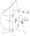
- Fig. 6 and Fig. 7 respectively show a perspective view and a perspective exploded view of a connection part between the supporting plate of the rotor of the motor and the shaft connection unit according to the third embodiment of the present disclosure.
- at least one slot S1 is formed on a surface of one of the first connection portion C1 and the second connection portion C2 facing to the other of the first connection portion (C1) and the second connection portion (C2), and a pair of wedges W1 opposite to each other are inserted and arranged in each slot S1.
- the first connection portion C1 is a rectangular parallelepiped block-like convex connection portion, and has two corners at an end thereof facing to the second connection portion C2.
- the two corners of the first connection portion C1 are denoted as a first corner and a second corner.
- the second connection portion C2 is a rectangular parallelepiped concave connection portion; the concave connection portion penetrates two opposite surfaces of the shaft connection unit 210 in an axial direction, thereby having a first wall surface facing to the supporting plate 221 and a second wall surface and a third wall surface connected to the first wall surface; herein, the second wall surface and the third wall surface are arranged opposite to each other.
- the above-mentioned first corner is in contact with the above-mentioned first wall surface and the above-mentioned second wall surface; the above-mentioned second corner is in contact with the above-mentioned first wall surface and the first connection portion C1 of the adjacent supporting plate 221.
- the slot S1 is arranged at the above-mentioned first corner.
- the pair of wedges W1 are inserted into the slot S1 in the axial direction opposite to each other, so that connection surfaces at a position where the supporting plate 221 and the shaft connection unit 210 are connected are more closely fitted, which can effectively ensure torque transmission and increase structural stability.
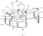
- Fig. 8 shows a perspective view of the rotor of the motor according to a fourth embodiment of the present disclosure.
- the rotor of the motor includes the magnetic yoke 100, the rotor support 200 and the end plate 300; the specific structures and connection relationships of the magnetic yoke 100, the rotor support 200 and the end plate 300 in the fourth embodiment are substantially the same as the corresponding structures and connection relationships in the third embodiment.
- the magnetic yoke 100 includes the plurality of magnetic yoke segments 110 which are successively spliced into the cylindrical-like body in the circumference direction.
- the supporting ring 220 includes the plurality of supporting plates 221, the plurality of the supporting plates 221 are successively spliced into the annular sheet-like body in the circumference direction.
- the end plate 300 includes the plurality of end plate segments 310, the plurality of end plate segments 310 are successively spliced into the annular sheet-like body in the circumference direction.
- the number of the magnetic yoke segments 110 is twice of the number of the supporting plates 221; the number of the magnetic yoke segments 110 is also twice of the number of end plate segments 310; the supporting plates 221 are arranged to be spaced apart the end plate segments 310 in one-to-one correspondence; two supporting plates 221 are connected between each pair of supporting plate 221 and the end plate segment 310 which are arranged to be spaced apart.
- the magnetic yoke segment 110 with a curved structure is divided into more segments, which can further improve the convenience of transportation.
- the supporting ring 220 has the structure divided into the plurality of segments in the circumference direction of itself, the supporting ring 220 includes the plurality of supporting plates 221, the plurality of the supporting plates 221 are successively spliced into an annular sheet-like body in the circumference direction, and the adjacent supporting plates 221 are connected by a connection assembly 400.
- the magnetic yoke 100 has the structure divided into the plurality of segments in the circumference direction of itself, the magnetic yoke 100 includes the plurality of magnetic yoke segments 110, the plurality of magnetic yoke segments 110 are successively spliced into a cylindrical-like body in the circumference direction, and the adjacent magnetic yoke segments 110 are connected by the connection assembly 400.
- the end plate 300 has the structure divided into the plurality of segments in the circumference direction of itself, the end plate 300 includes a plurality of end plate segments 310, the plurality of end plate segments 310 are successively spliced into an annular sheet-like body in the circumference direction, and the adjacent end plate segments 310 are connected by the connection assembly 400.
- the shaft connection unit 210 and the supporting ring 220 are connected by the connection assembly 400.
- the supporting ring 220 has the structure divided into the plurality of segments in the circumference direction of itself; the supporting ring 220 includes the plurality of supporting plates 221; each supporting plate 221 is provided with the first connection portion C1; the outer periphery of the shaft connection unit 210 is provided with the second connection portion C2, and the first connection portion C1 of each supporting plate (221) is connected to the second connection portion C2 of the shaft connection unit 210 by the connection assembly 400.
- the adjacent supporting plates 221 and the adjacent magnetic yoke segments 110 are connected by the connection assembly 400.
- each pair of adjacent supporting plates 221 can be connected by a set of connection assemblies 400; each pair of adjacent magnetic yoke segments 110 can be connected by the set of connection assemblies 400.
- the number of connection assemblies 400 arranged between each pair of the adjacent magnetic yoke segments 110, between each pair of the adjacent supporting plates 221, between each pair of the adjacent end plate segments 310, and between the shaft connection unit 210 and the supporting ring 220 may be adjusted and set as needed.
- Fig. 9 shows a perspective exploded view of the connection assembly in the rotor of the motor according to the fourth embodiment of the present disclosure.
- the connection assembly 400 connecting with adjacent magnetic yoke segments 110 is taken as an example for illustration, the connection assembly 400 connecting with the adjacent supporting plates 221, and the connection assembly 400 connecting with the adjacent end plate segments 310 are similar in structure to this connection assembly 400, and will not be described in detail.
- the adjacent magnetic yoke segments 110 form a first pin hole H1 at the splicing position.
- the first pin hole H1 is simultaneously formed at the splicing position by the adjacent magnetic yoke segments 110; each magnetic yoke segment 110 has a half structure of the first pin hole H1 at the splicing position, so that when the adjacent magnetic yoke segments 110 are spliced, the complete first pin hole H1 can be formed.
- first pin hole H1 is not limited to being simultaneously formed by the adjacent magnetic yoke segments 110; in some other embodiments, the first pin holes H1 can also be completely formed on a surface of at least any one of the adjacent magnetic yoke segments 110, and the number and the size of the first pin holes H1 can be adjusted and designed according to the magnitude of the load.
- connection assembly 400 when the connection assembly 400 is connected to the adjacent supporting plate 221, or the adjacent end plate segments 310, or the shaft connection unit 210 and the supporting ring 220, the above-mentioned first pin hole H1 may also be formed at the splicing position of the adjacent supporting plates 221 or the adjacent end plate segments 310 or the shaft connection unit 210 and the supporting ring 220.
- connection assembly 400 of the embodiment in the present disclosure includes a connection base plate 410 and a pin block 420.
- the connection base plate 410 is connected to the adjacent magnetic yoke segments 110.
- connection base plate 410 is provided with a second connection hole H4 corresponding to a position of the first connection hole H3; the second connection hole H4 on the connection base plate 410 is connected and fixed to the corresponding first connection hole H3 by a first screw bolt B1 penetrating through a first gasket G1.
- each magnetic yoke segment 110 has the first connection hole H3; the connection base plate 410 is provided with the second connection hole H4 corresponding to a position of the first connection hole H3 of the adjacent magnetic yoke segment 110; the second connection holes H4 of the connection base plate 410 are respectively connected and fixed to the first connection holes H3 of the adjacent magnetic yoke segments 110 by the first screw bolt B1 penetrating through the first gasket G1, so as to realize the connection of the adjacent magnetic yoke segments 110.
- connection base plate 410 may be connected to the adjacent supporting plates 221, or connecting with the adjacent end plate segments 310, or connecting with the shaft connection unit 210 and the supporting ring 220.
- connection base plate 410 is provided with a second pin hole H2 corresponding to a position of the first pin hole H1; the pin block 420 connects the second pin hole H2 with the first pin hole H1, and the pin block 420 is fixed to the connection base plate 410.
- connection base plate 410 is provided with a third connection hole H5 around a periphery of the second pin hole H2;
- the pin block 420 is in a stepped cylindrical-like shape and is provided with a fourth connection hole H6 corresponding to a position of the third connection hole H5;
- the third connection hole H5 of the pin block 420 is connected and fixed to the fourth connection hole H6 of the connection base plate 410 by a second screw bolt B2 penetrating through a second gasket G2, so as to realize the connection of the pin block 420 and the connection base plate 410.
- the second pin hole H2 and the first pin hole H1 are positioned and connected to each other by the pin block 420.
- the specific number of the first screw bolts B1 and the pin blocks 420 in the connection assembly 400 may be determined by actual conditions.
- the first screw bolt B1 and the pin block 420 are arranged in the connection assembly 400, so that a connection structure formed by the connection assembly 400 and the adjacent magnetic yoke segments110, or the adjacent supporting plates 221, or the adjacent end plate segments 310 can effectively bear the loads in the axial direction and a tangential direction.
- the connection process of the above structure is simple and convenient to assemble.
- the first pin hole H1 and the first connection hole H3 may be blind holes formed on a surface of the magnetic yoke segment 110 facing to the connection base plate 410, so as to prevent the pin block 420 and the first screw bolt B1 from penetrating the magnetic yoke segment 110.
- the blind hole design of the first pin hole H1 and the first connection hole H3 can avoid interference caused by the pin block 420 and the first screw bolt B1 when the magnet is installed.
- the motor is further provided by the embodiment of the present disclosure, the motor can be applied to the wind-power electric generator set for electric generation; the wind power electric generator is, for example, a direct-drive permanent-magnet wind-power electric generator.
- the motor includes a fixed shaft, a rotation shaft, the stator and a rotor assembly.
- the fixed shaft is fixedly arranged in a nacelle of the wind-power electric generator set, the rotation shaft is coaxially connected with the fixed shaft through a bearing, and the rotation shaft can be connected with a hub and blades of the wind-power electric generator set so as to be able to rotate.
- the stator is coaxially fixed with the fixed shaft, the stator may include a stator iron core and a stator winding set.
- the rotor assembly is coaxially connected with the rotation shaft, the rotor assembly may include the rotor of the motor of any one of the above embodiments; the rotor support 200 of the rotor of the motor is connected to the rotation shaft and is adapted to rotate with the rotation shaft relative to the stator, the magnet is arranged on the circumference surface of the magnetic yoke 100 of the rotor of the motor.
- the motor is the outer-rotor-type motor
- the magnet is arranged on the inner circumference surface of the magnetic yoke 100 of the rotor of the motor;
- the motor is the inner-rotor-type motor, the magnet is arranged on the outer circumference surface of the magnetic yoke 100 of the rotor of the motor.
- the stator winding set included in the stator cuts the magnetic force lines formed by the magnet on the rotor assembly, thereby generating electricity.
- the rotor of the motor includes the rotor support 200 and the magnetic yoke 100; at least the supporting ring 220 and in particular the magnetic yoke 100 of the rotor support 200 has the structure divided into the plurality of segments in the circumference direction of itself, so that the supporting ring 220 and in particular the magnetic yoke 100 can be split into the plurality of segment units; when needed, the plurality of segment units can be spliced to each other to obtain the complete rotor support 200 and the complete magnetic yoke 100, further to obtain the complete rotor structure.
- the volume of the plurality of segment units can be significantly smaller than the volume of the overall rotor, which is convenient for the transportation and store of the rotor while ensuring that the complete rotor can meet the power requirement.
- the transportation cost can be reduced.
- the repair can be achieved by replacing the segmented unit of the faulty part; for example, when the magnetic yoke 100 has the structure divided into the plurality of segments in the circumference direction of itself, it may include the plurality of magnetic yoke segments 110 spliced with each other; if one of the magnetic yoke segments 110 fails, only the new magnetic yoke segment 110 needs to be used to replace the faulty magnetic yoke segment 110 to continue the stable operation of the rotor of the motor, thereby saving the maintenance cost of the rotor of the motor.
- At least the supporting ring 220 and in particular the magnetic yoke 100 of the rotor support 200 has the structure divided into the plurality of segments in the circumference direction of itself, so that at least the supporting ring 220 and in particular the magnetic yoke 100 of the rotor support 200 can be divided into the plurality of segment units.
- a process for maintaining the rotor of the motor is, for example: detecting the rotor of the motor, identifying a defective segment unit; then separating the defective segment unit from the rotor of the motor, so that the rotor of the motor has an area to be filled; and then installing a non-defective segment unit having a same function as the defective segment unit into the area to be filled of the rotor of the motor to obtain the repaired rotor of the motor.
- a manual detection can be performed, or a detection can be performed by a matching detection device.
- the process for maintaining the rotor of the motor can be performed on a top of a tower column of the wind-power electric generator set, without the need to transport the rotor of the motor to the bottom of the tower column (such as the ground or the sea) for maintenance.
- a weight of the defective segment unit is much lower than a weight of the entire rotor of the motor
- a conventional hoisting equipment in the field of the wind-power electric generator set can be used to transport the rotor of the motor to the ground or the sea.
- a weight of the non-defective segment unit is much lower than the weight of the entire rotor of the motor.
- the conventional hoisting equipment in the field of the wind-power electric generator set can be used to transport the rotor of the motor from the ground or sea to the top of the tower column, and then the non-defective segment unit is installed in the area to be filled of the rotor of the motor through the matching positioning equipment.
- the rotor of the motor further includes the end plate 300, the end plate 300 is in the ring-like shape and arranged coaxially with and spaced apart from the supporting ring 220 of the rotor support 200, and the supporting ring 220 and the end plate 300 are respectively arranged at two ends of the magnetic yoke 100 in the axial direction.
- At least the supporting ring 220 and in particular the magnetic yoke 100 and/or the end plate 300 has the structure divided into the plurality of segments in the circumference direction, so that at least the supporting ring 220 and in particular the magnetic yoke 100 and/or the end plate 300 can be divided into the plurality of segment units.
- each of the magnetic yoke 100, the supporting ring 220 and the end plate 300 has the structure divided into the plurality of segments in the circumference direction, so that each of the magnetic yoke 100, the supporting ring 220 and the end plate 300 can be divided into the plurality of segment units.
- a certain segment unit fails, it is only necessary to replace the faulty segment unit with a corresponding new segment unit to achieve repairing the rotor of the motor, thereby saving the maintenance cost of the rotor of the motor.
- the wind-power electric generator set is further provided by the embodiment of the present disclosure, including an impeller, and the motor according to any one of the embodiments as described above; the rotation shaft of the motor is coaxially connected with the impeller, so that the impeller drives the rotation shaft of the motor to rotate when the impeller rotates in the wind.
- the impeller may include a hub and a plurality of blades connected to the hub.
- the wind-power electric generator set also includes the tower column and a nacelle arranged on the tower column.
- the motor also includes the fixed shaft, the stator and the rotor assembly.
- the fixed shaft is arranged and fixed in the nacelle of the wind-power electric generator set, and the rotation shaft is coaxially connected with the fixed shaft through the bearing.
- the stator is coaxially fixed with the fixed shaft, and the stator may include a stator core and a stator winding set.
- the rotor assembly is coaxially connected with the rotation shaft, the rotor assembly may include the rotor of the motor according to any one of the embodiments as described above.
- the rotor support 200 of the rotor of the motor is connected to the rotation shaft and can rotate with the rotation shaft relative to the stator.
- the magnet is arranged on the circumference surface of the magnetic yoke 100 of the rotor of the motor.
- the rotor of the motor includes the rotor support 200 and the magnetic yoke 100; at least the supporting ring 220 and in particular the magnetic yoke 100 of the rotor support 200 has the structure divided into the plurality of segments in the circumference direction of itself, so that the supporting ring 220 and in particular the magnetic yoke 100 can be split into the plurality of segment units; when needed, the plurality of segment units can be spliced to each other to obtain the complete rotor support 200 and the complete magnetic yoke 100, further to obtain the complete rotor structure.
- the volume of the plurality of segment units can be significantly smaller than the volume of the overall rotor, which is convenient for the transportation and store of the rotor while ensuring that the complete rotor can meet the power requirement.
- the transportation cost can be reduced.
- the repair can be achieved by replacing the segment unit in the faulty part, thereby reducing the maintenance cost of the wind-power electric generator set.
Landscapes
- Engineering & Computer Science (AREA)
- Power Engineering (AREA)
- Iron Core Of Rotating Electric Machines (AREA)
- Manufacture Of Motors, Generators (AREA)
- Connection Of Motors, Electrical Generators, Mechanical Devices, And The Like (AREA)
- Permanent Field Magnets Of Synchronous Machinery (AREA)
Claims (12)
- Rotor für einen Motor, umfassendein Magnetjoch (100), wobei das Magnetjoch (100) eine zylinderähnliche Form aufweist und das Magnetjoch (100) dazu ausgestaltet ist, einen Magneten an seiner Umfangsfläche zu befestigen; undeinen Rotorträger (200), umfassend eine Wellenverbindungseinheit (210) und einen Trägerring (220), wobei die Wellenverbindungseinheit (210) koaxial mit einer Rotationswelle des Motors verbunden ist, der Trägerring (220) an einem Außenumfang der Wellenverbindungseinheit (210) angeordnet ist, und das Magnetjoch (100) so angeordnet ist, dass es koaxial mit dem Trägerring (220) verbunden ist;wobei der Trägerring (220) eine Struktur aufweist, die in ihrer Umfangsrichtung in eine Mehrzahl von Segmenten unterteilt ist, der Trägerring (220) eine Mehrzahl von Trägerplatten (221) umfasst, die Mehrzahl von Trägerplatten (221) in der Umfangsrichtung nacheinander zu einem ringförmigen flächigen Körper gespleißt sind, jede Trägerplatte (221) mit einem ersten Verbindungsabschnitt (C1) versehen ist, die Wellenverbindungseinheit (210) an ihrem Außenumfang mit einem zweiten Verbindungsabschnitt (C2) versehen ist, und die Mehrzahl von Trägerplatten (221) mit dem zweiten Verbindungsabschnitt (C2) der Wellenverbindungseinheit (210) durch die ersten Verbindungsabschnitte (C1) verbunden sind;mindestens ein Schlitz (S1) auf einer Oberfläche eines aus dem ersten Verbindungsabschnitt (C1) und dem zweiten Verbindungsabschnitt (C2) gebildet ist, der dem anderen aus dem ersten Verbindungsabschnitt (C1) und dem zweiten Verbindungsabschnitt (C2) zugewandt ist, der andere aus dem ersten Verbindungsteil (C1) und dem zweiten Verbindungsteil (C2) ein konvexer Verbindungsabschnitt ist, der in seiner Form an den Schlitz (S1) angepasst ist, und in jedem Schlitz (S1) ein Paar einander gegenüberliegender Keile (W1) eingefügt und angeordnet sind.
- Rotor für einen Motor nach Anspruch 1, wobei sich die Trägerplatte (221) in einer bogenförmigen Richtung erstreckt und zwei gegenüberliegende Enden in der sich erstreckenden bogenförmigen Richtung aufweist, wobei sich der erste Verbindungsabschnitt (C1) zwischen den beiden Enden der Trägerplatte (221) befindet.
- Rotor für einen Motor nach Anspruch 1, wobei sich die Trägerplatte (221) in einer bogenförmigen Richtung erstreckt und zwei gegenüberliegende Enden in der sich erstreckenden bogenförmigen Richtung aufweist, wobei die ersten Verbindungsabschnitte (C1) jeweils an zwei Enden der Trägerplatte (221) angeordnet sind;
wobei zwei erste Verbindungsabschnitte (C1) von zwei benachbarten Trägerplatten (221) in einer gleichen Spleißposition entsprechend mit einem zweiten Verbindungsabschnitt (C2) der Wellenverbindungseinheit (210) verbunden sind. - Rotor für einen Motor nach Anspruch 1, ferner umfassend:eine Endplatte (300), wobei die Endplatte (300) eine ringähnliche Form aufweist und koaxial mit und beabstandet von dem Trägerring (220) angeordnet ist,wobei der Trägerring (220) und die Endplatte (300) jeweils an zwei Enden des Magnetjochs (100) in einer axialen Richtung angeordnet sind.
- Rotor für einen Motor nach Anspruch 4, wobei der Trägerring (220) die Struktur aufweist, die in ihrer Umfangsrichtung in eine Mehrzahl von Segmenten unterteilt ist, der Trägerring (220) eine Mehrzahl von Trägerplatten (221) umfasst, die Mehrzahl von Trägerplatten (221) in der Umfangsrichtung nacheinander zu einem ringförmigen flächigen Körper gespleißt sind, die benachbarten Trägerplatten (221) durch eine Verbindungsbaugruppe (400) verbunden sind, die benachbarten Trägerplatten (221) oder die Wellenverbindungseinheit (210) und der Trägerring (220) an einer Spleißposition ein erstes Stiftloch (H1) ausbilden;und/oder das Magnetjoch (100) die Struktur aufweist, die in ihrer Umfangsrichtung in eine Mehrzahl von Segmenten unterteilt ist, das Magnetjoch (100) eine Mehrzahl von Magnetjochsegmenten (110) umfasst, die Mehrzahl von Magnetjochsegmenten (110) in der Umfangsrichtung nacheinander zu einem zylinderähnlichen Körper gespleißt sind, die benachbarten Magnetjochsegmente (110) durch eine Verbindungsbaugruppe (400) verbunden sind, die benachbarten Magnetjochsegmente (110) an einer Spleißposition ein erstes Stiftloch (H1) ausbilden;
und/oder die Endplatte (300) die Struktur aufweist, die in ihrer Umfangsrichtung in eine Mehrzahl von Segmenten unterteilt ist, die Endplatte (300) eine Mehrzahl von Endplattensegmenten (310) umfasst, die Mehrzahl von Endplattensegmenten (310) in der Umfangsrichtung nacheinander zu einem ringförmigen flächigen Körper gespleißt sind, die benachbarten Endplattensegmente (310) durch eine Verbindungsbaugruppe (400) verbunden sind, die benachbarten Endplattensegmente (310) an einer Spleißposition ein erstes Stiftloch (H1) ausbilden;und/oder die Wellenverbindungseinheit (210) und der Trägerring (220) durch eine Verbindungsbaugruppe (400) verbunden sind;wobei die Verbindungsbaugruppe (400) umfasst:eine Verbindungsbasisplatte (410) zum Verbinden mit den benachbarten Trägerplatten (221) oder zum Verbinden mit den benachbarten Magnetjochsegmenten (110) oder zum Verbinden mit den benachbarten Endplattensegmenten (310) oder zum Verbinden der Wellenverbindungseinheit (210) mit dem Trägerring (220), wobei die Verbindungsbasisplatte (410) mit einem zweiten Stiftloch (H2) versehen ist, das einer Position des ersten Stiftlochs (H1) entspricht; undeinen Stiftblock (420), der das zweite Stiftloch (H2) mit dem ersten Stiftloch (H1) verbindet und an der Verbindungsbasisplatte (410) befestigt ist. - Rotor für einen Motor nach Anspruch 5, wobei an jeder Spleißposition zwischen den benachbarten Trägerplatten (221) oder zwischen den benachbarten Magnetjochsegmenten (110) oder zwischen den benachbarten Endplattensegmenten (310) oder zwischen der Wellenverbindungseinheit (210) und dem Trägerring (220) ein erstes Verbindungsloch (H3) vorhanden ist; die Verbindungsbasisplatte (410) mit einem zweiten Verbindungsloch (H4) versehen ist, das einer Position des ersten Verbindungslochs (H3) entspricht; das zweite Verbindungsloch (H4) der Verbindungsbasisplatte (410) mit dem entsprechenden ersten Verbindungsloch (H3) durch einen ersten Schraubenbolzen (B1) verbunden und befestigt ist, der durch eine erste Dichtung (G1) hindurchgeht; oder
die Verbindungsbasisplatte (410) mit einem dritten Verbindungsloch (H5) um einen Umfang des zweiten Stiftlochs (H2) herum versehen ist; der Stiftblock (420) eine abgestufte zylinderähnliche Form aufweist und mit einem vierten Verbindungsloch (H6) versehen ist, das einer Position des dritten Verbindungslochs (H5) entspricht; das dritte Verbindungsloch (H5) des Stiftblocks (420) mit dem vierten Verbindungsloch (H6) der Verbindungsbasisplatte (410) durch einen zweiten Schraubenbolzen (B2) verbunden und befestigt ist, der durch eine zweite Dichtung (G2) hindurchgeht. - Rotor für einen Motor nach Anspruch 4, wobei der Trägerring (220) die Struktur aufweist, die in ihrer Umfangsrichtung in eine Mehrzahl von Segmenten unterteilt ist, und eine Mehrzahl von Trägerplatten (221) umfasst, die Mehrzahl von Trägerplatten (221) in der Umfangsrichtung nacheinander zu einem ringförmigen flächigen Körper gespleißt sind, eine erste Spleißfläche zwischen den benachbarten Trägerplatten (221) ausgebildet ist;das Magnetjoch (100) die Struktur aufweist, die in ihrer Umfangsrichtung in die Mehrzahl von Segmenten unterteilt ist, das Magnetjoch (100) eine Mehrzahl von Magnetjochsegmenten (110) umfasst, die Mehrzahl von Magnetjochsegmenten (110) in der Umfangsrichtung nacheinander zu einem zylinderähnlichen Körper gespleißt sind, eine zweite Spleißfläche zwischen den benachbarten Magnetjochsegmenten (110) ausgebildet ist;die Endplatte (300) die Struktur aufweist, die in ihrer Umfangsrichtung in die Mehrzahl von Segmenten unterteilt ist, die Endplatte (300) eine Mehrzahl von Endplattensegmenten (310) umfasst, die Mehrzahl von Endplattensegmenten (310) in der Umfangsrichtung nacheinander zu einem ringförmigen flächigen Körper gespleißt sind, eine dritte Spleißfläche zwischen den benachbarten Endplattensegmenten (310) ausgebildet ist;wobei mindestens zwei aus der ersten Spleißfläche, der zweiten Spleißfläche und der dritten Spleißfläche so angeordnet sind, dass sie zueinander versetzt sind;wobei der Rotor des Motors ferner ein Dichtungsmittel umfasst, das mindestens eine aus der ersten Spleißfläche, der zweiten Spleißfläche und der dritten Spleißfläche abdeckt.
- Rotor für einen Motor nach Anspruch 1, wobei der Trägerring (220) die Struktur aufweist, die in ihrer Umfangsrichtung in eine Mehrzahl von Segmenten unterteilt ist, und eine Mehrzahl von Trägerplatten (221) umfasst, wobei die Mehrzahl von Trägerplatten (221) in der Umfangsrichtung nacheinander zu einem ringförmigen flächigen Körper gespleißt sind; das Magnetjoch (100) die Struktur aufweist, die in ihrer Umfangsrichtung in die Mehrzahl von Segmenten unterteilt ist, das Magnetjoch (100) eine Mehrzahl von Magnetjochsegmenten (110) umfasst, die Mehrzahl von Magnetjochsegmenten (110) in der Umfangsrichtung nacheinander zu einem zylinderähnlichen Körper gespleißt sind,
wobei die Anzahl der Magnetjochsegmente (110) ein beliebiges positives ganzzahliges Vielfaches der Anzahl der Trägerplatten (221) ist. - Rotor für einen Motor nach Anspruch 1, wobei die Wellenverbindungseinheit (210) einen zentralen Verbindungsabschnitt (211) und eine Mehrzahl von Verbindungsarmen (212) umfasst, die strahlenförmig an einem Außenumfang des zentralen Verbindungsabschnitts (211) verteilt sind; der zentrale Verbindungsabschnitt (211) mit einem Durchgangsloch (H9) versehen ist, das mit der Rotationswelle des Motors zusammenpasst, und die Mehrzahl von Verbindungsarmen (212) mit dem Trägerring (220) verbunden sind;wobei der zentrale Verbindungsabschnitt (211) mit der Rotationswelle des Motors über einen Verbindungsflansch verbunden ist, der koaxial zum zentralen Verbindungsabschnitt (211) angeordnet ist;wobei ein Raum zwischen dem zentralen Verbindungsabschnitt (211) und dem Trägerring (220) durch die Mehrzahl von Verbindungsarmen (212) in eine Mehrzahl von Hohlbereichen (CA) unterteilt ist,wobei der Rotor des Motors ferner umfasst:eine Abdeckplatte, die so angeordnet ist, dass sie die Hohlbereiche (CA) abdeckt; odereine Filtereinheit, die im Hohlbereich (CA) angeordnet ist.
- Verfahren zur Wartung des Rotors für einen Motor nach einem der Ansprüche 1 bis 9; wobei das Verfahren zur Wartung des Rotors für einen Motor umfasst:Erkennen des Rotors für einen Motor und Identifizieren einer defekten Segmenteinheit;Trennen der defekten Segmenteinheit von dem Rotor für einen Motor, sodass der Rotor für einen Motor einen zu füllenden Bereich aufweist; undInstallieren einer nicht defekten Segmenteinheit, die die gleiche Funktion wie die defekte Segmenteinheit aufweist, in den zu füllenden Bereich des Rotors für einen Motor, um den reparierten Rotor des Motors zu erhalten.
- Motor, umfassend:eine feste Welle;eine Rotationswelle, die über ein Lager koaxial mit der festen Welle verbunden ist, und wobei die Rotationswelle dazu ausgelegt ist, sich zu drehen;einen Stator, der koaxial an der festen Welle befestigt ist; undeine Rotorbaugruppe, die koaxial mit der Rotationswelle verbunden ist;dadurch gekennzeichnet, dass die Rotorbaugruppe den Rotor für einen Motor nach einem der Ansprüche 1 bis 9 umfasst und der Rotorträger (200) des Rotors für einen Motor mit der Rotationswelle verbunden ist und dazu ausgelegt ist, sich mit der Rotationswelle relativ zum Stator zu drehen, wobei ein Magnet auf der Umfangsfläche des Magnetjochs (100) des Rotors für einen Motor angeordnet ist.
- Satz elektrischer Windkraftgeneratoren, umfassend:ein Laufrad, undden Motor nach Anspruch 11, wobei die Rotationswelle des Motors koaxial mit dem Laufrad verbunden ist.
Applications Claiming Priority (2)
| Application Number | Priority Date | Filing Date | Title |
|---|---|---|---|
| CN201910293934.1A CN109950994B (zh) | 2019-04-12 | 2019-04-12 | 电机转子及电机 |
| PCT/CN2020/074542 WO2020207107A1 (zh) | 2019-04-12 | 2020-02-07 | 电机转子及其维护方法、电机、风力发电机组 |
Publications (4)
| Publication Number | Publication Date |
|---|---|
| EP3940924A1 EP3940924A1 (de) | 2022-01-19 |
| EP3940924A4 EP3940924A4 (de) | 2022-05-11 |
| EP3940924C0 EP3940924C0 (de) | 2024-03-13 |
| EP3940924B1 true EP3940924B1 (de) | 2024-03-13 |
Family
ID=67014971
Family Applications (1)
| Application Number | Title | Priority Date | Filing Date |
|---|---|---|---|
| EP20787468.6A Active EP3940924B1 (de) | 2019-04-12 | 2020-02-07 | Rotor eines motors, verfahren zur wartung des rotors eines motors, motor und elektrische windkraftanlage |
Country Status (5)
| Country | Link |
|---|---|
| US (1) | US20220200381A1 (de) |
| EP (1) | EP3940924B1 (de) |
| CN (1) | CN109950994B (de) |
| AU (1) | AU2020256485B2 (de) |
| WO (1) | WO2020207107A1 (de) |
Families Citing this family (2)
| Publication number | Priority date | Publication date | Assignee | Title |
|---|---|---|---|---|
| CN109950994B (zh) * | 2019-04-12 | 2020-08-11 | 新疆金风科技股份有限公司 | 电机转子及电机 |
| CN113014013B (zh) * | 2019-12-20 | 2023-06-09 | 新疆金风科技股份有限公司 | 转子支架、转子、电机及风力发电机组 |
Citations (2)
| Publication number | Priority date | Publication date | Assignee | Title |
|---|---|---|---|---|
| GB303906A (en) * | 1928-01-13 | 1930-06-12 | British Thomson Houston Co Ltd | Improvements in and relating to rotors for dynamo electric machines |
| WO2011002763A1 (en) * | 2009-07-02 | 2011-01-06 | Via Wind Energy, Llc | Wind generator |
Family Cites Families (10)
| Publication number | Priority date | Publication date | Assignee | Title |
|---|---|---|---|---|
| GB191210507A (en) * | 1911-05-04 | 1912-10-24 | Rudolf Goldschmidt | Improvements in and pertaining to High-speed Rotors for High-frequency Multipolar Electrical Machinery. |
| JPS5951221B2 (ja) * | 1979-11-14 | 1984-12-12 | 三菱電機株式会社 | 回転電機の回転子の製造方法 |
| CN201536286U (zh) * | 2009-10-04 | 2010-07-28 | 李春光 | 轮状低速永磁风力发电机转子 |
| IT1397782B1 (it) * | 2010-01-15 | 2013-01-24 | Gate Srl | Rotore a magneti permanenti per un motore elettrico brushless in corrente continua |
| US20130181571A1 (en) * | 2012-01-17 | 2013-07-18 | Hsiu-Mei Chang | Structure for Electrical Machines |
| EP2621056B1 (de) * | 2012-01-27 | 2016-10-26 | ALSTOM Renewable Technologies | Rotoranordnung für einen Windturbinengenerator |
| GB2505475B (en) * | 2012-08-31 | 2015-11-18 | Lappeenranta University Of Technology | Compressing a laminated stack in an electrical machine |
| US10862359B2 (en) * | 2015-11-26 | 2020-12-08 | Mitsubishi Electric Corporation | Rotor, motor, air-conditioning apparatus, and method for manufacturing rotor |
| CN209709790U (zh) * | 2019-04-12 | 2019-11-29 | 新疆金风科技股份有限公司 | 电机转子支架及电机 |
| CN109950994B (zh) * | 2019-04-12 | 2020-08-11 | 新疆金风科技股份有限公司 | 电机转子及电机 |
-
2019
- 2019-04-12 CN CN201910293934.1A patent/CN109950994B/zh active Active
-
2020
- 2020-02-07 WO PCT/CN2020/074542 patent/WO2020207107A1/zh unknown
- 2020-02-07 EP EP20787468.6A patent/EP3940924B1/de active Active
- 2020-02-07 US US17/594,334 patent/US20220200381A1/en active Pending
- 2020-02-07 AU AU2020256485A patent/AU2020256485B2/en active Active
Patent Citations (2)
| Publication number | Priority date | Publication date | Assignee | Title |
|---|---|---|---|---|
| GB303906A (en) * | 1928-01-13 | 1930-06-12 | British Thomson Houston Co Ltd | Improvements in and relating to rotors for dynamo electric machines |
| WO2011002763A1 (en) * | 2009-07-02 | 2011-01-06 | Via Wind Energy, Llc | Wind generator |
Also Published As
| Publication number | Publication date |
|---|---|
| CN109950994B (zh) | 2020-08-11 |
| EP3940924C0 (de) | 2024-03-13 |
| US20220200381A1 (en) | 2022-06-23 |
| WO2020207107A1 (zh) | 2020-10-15 |
| EP3940924A1 (de) | 2022-01-19 |
| CN109950994A (zh) | 2019-06-28 |
| AU2020256485A1 (en) | 2021-11-11 |
| EP3940924A4 (de) | 2022-05-11 |
| AU2020256485B2 (en) | 2023-05-11 |
Similar Documents
| Publication | Publication Date | Title |
|---|---|---|
| CA2832114C (en) | Method for assembling an electrical machine | |
| CA2681120C (en) | Stator arrangement, generator and wind turbine | |
| EP1173915B1 (de) | Generator für ein windrad, statorbaueinheit für den generator und verwendung des generators | |
| EP3940924B1 (de) | Rotor eines motors, verfahren zur wartung des rotors eines motors, motor und elektrische windkraftanlage | |
| US20190348881A1 (en) | Electric generator having multiple electrical machines | |
| CN102695875A (zh) | 风力涡轮机 | |
| DK177374B1 (en) | Cooling structure for a segmented stator assembly | |
| CN204835868U (zh) | 垂直轴双转子发电机 | |
| US20220069649A1 (en) | A generator rotor assembly | |
| US10840753B2 (en) | Magnet module and electrical machine | |
| CN106662077A (zh) | 具有直接驱动的发电机的风力发电设备 | |
| US20230231426A1 (en) | Segment support structure for a generator of a wind turbine | |
| EP2621056B1 (de) | Rotoranordnung für einen Windturbinengenerator | |
| CN105339670A (zh) | 泵装置 | |
| JP2022140305A (ja) | 発電機補剛リング | |
| JP4848895B2 (ja) | 立軸回転電機の回転子 | |
| CN207321074U (zh) | 多转子多定子无铁芯电机定子结构 | |
| CN219135076U (zh) | 风力发电机的定转子固定装置 | |
| KR101281537B1 (ko) | 아웃로터 타입의 수직축 풍력발전기의 구조 및 조립방법 | |
| CN112366864B (zh) | 电机转子、电机及电机转子的安装方法 | |
| CN218940801U (zh) | 一种防漏磁的磁力泵转子 | |
| CN117060634A (zh) | 一种增强型单侧悬臂式直驱电机 | |
| JPS5930591Y2 (ja) | 回転電機の固定子構造 | |
| CN110858729A (zh) | 电机组件与洗衣机 | |
| WO2021008663A1 (en) | Improvements relating to wind turbine main rotor turning systems |
Legal Events
| Date | Code | Title | Description |
|---|---|---|---|
| STAA | Information on the status of an ep patent application or granted ep patent |
Free format text: STATUS: THE INTERNATIONAL PUBLICATION HAS BEEN MADE |
|
| PUAI | Public reference made under article 153(3) epc to a published international application that has entered the european phase |
Free format text: ORIGINAL CODE: 0009012 |
|
| STAA | Information on the status of an ep patent application or granted ep patent |
Free format text: STATUS: REQUEST FOR EXAMINATION WAS MADE |
|
| 17P | Request for examination filed |
Effective date: 20211013 |
|
| AK | Designated contracting states |
Kind code of ref document: A1 Designated state(s): AL AT BE BG CH CY CZ DE DK EE ES FI FR GB GR HR HU IE IS IT LI LT LU LV MC MK MT NL NO PL PT RO RS SE SI SK SM TR |
|
| A4 | Supplementary search report drawn up and despatched |
Effective date: 20220413 |
|
| RIC1 | Information provided on ipc code assigned before grant |
Ipc: H02K 15/00 20060101ALN20220407BHEP Ipc: H02K 7/18 20060101ALN20220407BHEP Ipc: H02K 1/2791 20220101ALI20220407BHEP Ipc: H02K 1/30 20060101AFI20220407BHEP |
|
| DAV | Request for validation of the european patent (deleted) | ||
| DAX | Request for extension of the european patent (deleted) | ||
| STAA | Information on the status of an ep patent application or granted ep patent |
Free format text: STATUS: EXAMINATION IS IN PROGRESS |
|
| 17Q | First examination report despatched |
Effective date: 20230609 |
|
| GRAP | Despatch of communication of intention to grant a patent |
Free format text: ORIGINAL CODE: EPIDOSNIGR1 |
|
| STAA | Information on the status of an ep patent application or granted ep patent |
Free format text: STATUS: GRANT OF PATENT IS INTENDED |
|
| RIC1 | Information provided on ipc code assigned before grant |
Ipc: H02K 15/00 20060101ALN20231107BHEP Ipc: H02K 7/18 20060101ALN20231107BHEP Ipc: H02K 1/2791 20220101ALI20231107BHEP Ipc: H02K 1/30 20060101AFI20231107BHEP |
|
| INTG | Intention to grant announced |
Effective date: 20231124 |
|
| RIC1 | Information provided on ipc code assigned before grant |
Ipc: H02K 15/00 20060101ALN20231114BHEP Ipc: H02K 7/18 20060101ALN20231114BHEP Ipc: H02K 1/2791 20220101ALI20231114BHEP Ipc: H02K 1/30 20060101AFI20231114BHEP |
|
| GRAS | Grant fee paid |
Free format text: ORIGINAL CODE: EPIDOSNIGR3 |
|
| GRAA | (expected) grant |
Free format text: ORIGINAL CODE: 0009210 |
|
| STAA | Information on the status of an ep patent application or granted ep patent |
Free format text: STATUS: THE PATENT HAS BEEN GRANTED |
|
| AK | Designated contracting states |
Kind code of ref document: B1 Designated state(s): AL AT BE BG CH CY CZ DE DK EE ES FI FR GB GR HR HU IE IS IT LI LT LU LV MC MK MT NL NO PL PT RO RS SE SI SK SM TR |
|
| REG | Reference to a national code |
Ref country code: GB Ref legal event code: FG4D |
|
| REG | Reference to a national code |
Ref country code: CH Ref legal event code: EP |
|
| REG | Reference to a national code |
Ref country code: DE Ref legal event code: R096 Ref document number: 602020027263 Country of ref document: DE |
|
| REG | Reference to a national code |
Ref country code: IE Ref legal event code: FG4D |
|
| RAP4 | Party data changed (patent owner data changed or rights of a patent transferred) |
Owner name: GOLDWIND SCIENCE & TECHNOLOGY CO., LTD. |
|
| U01 | Request for unitary effect filed |
Effective date: 20240328 |
|
| U07 | Unitary effect registered |
Designated state(s): AT BE BG DE DK EE FI FR IT LT LU LV MT NL PT SE SI Effective date: 20240411 |