EP3940088A1 - Method of manufacturing titanium-containing ultra-low-carbon steel - Google Patents
Method of manufacturing titanium-containing ultra-low-carbon steel Download PDFInfo
- Publication number
- EP3940088A1 EP3940088A1 EP19919173.5A EP19919173A EP3940088A1 EP 3940088 A1 EP3940088 A1 EP 3940088A1 EP 19919173 A EP19919173 A EP 19919173A EP 3940088 A1 EP3940088 A1 EP 3940088A1
- Authority
- EP
- European Patent Office
- Prior art keywords
- molten steel
- donates
- flux
- addition
- degassing apparatus
- Prior art date
- Legal status (The legal status is an assumption and is not a legal conclusion. Google has not performed a legal analysis and makes no representation as to the accuracy of the status listed.)
- Granted
Links
Images

Classifications
-
- C—CHEMISTRY; METALLURGY
- C21—METALLURGY OF IRON
- C21C—PROCESSING OF PIG-IRON, e.g. REFINING, MANUFACTURE OF WROUGHT-IRON OR STEEL; TREATMENT IN MOLTEN STATE OF FERROUS ALLOYS
- C21C7/00—Treating molten ferrous alloys, e.g. steel, not covered by groups C21C1/00 - C21C5/00
- C21C7/04—Removing impurities by adding a treating agent
- C21C7/068—Decarburising
-
- C—CHEMISTRY; METALLURGY
- C21—METALLURGY OF IRON
- C21C—PROCESSING OF PIG-IRON, e.g. REFINING, MANUFACTURE OF WROUGHT-IRON OR STEEL; TREATMENT IN MOLTEN STATE OF FERROUS ALLOYS
- C21C7/00—Treating molten ferrous alloys, e.g. steel, not covered by groups C21C1/00 - C21C5/00
- C21C7/0006—Adding metallic additives
-
- C—CHEMISTRY; METALLURGY
- C21—METALLURGY OF IRON
- C21C—PROCESSING OF PIG-IRON, e.g. REFINING, MANUFACTURE OF WROUGHT-IRON OR STEEL; TREATMENT IN MOLTEN STATE OF FERROUS ALLOYS
- C21C7/00—Treating molten ferrous alloys, e.g. steel, not covered by groups C21C1/00 - C21C5/00
- C21C7/04—Removing impurities by adding a treating agent
- C21C7/06—Deoxidising, e.g. killing
-
- C—CHEMISTRY; METALLURGY
- C21—METALLURGY OF IRON
- C21C—PROCESSING OF PIG-IRON, e.g. REFINING, MANUFACTURE OF WROUGHT-IRON OR STEEL; TREATMENT IN MOLTEN STATE OF FERROUS ALLOYS
- C21C7/00—Treating molten ferrous alloys, e.g. steel, not covered by groups C21C1/00 - C21C5/00
- C21C7/04—Removing impurities by adding a treating agent
- C21C7/076—Use of slags or fluxes as treating agents
-
- C—CHEMISTRY; METALLURGY
- C21—METALLURGY OF IRON
- C21C—PROCESSING OF PIG-IRON, e.g. REFINING, MANUFACTURE OF WROUGHT-IRON OR STEEL; TREATMENT IN MOLTEN STATE OF FERROUS ALLOYS
- C21C7/00—Treating molten ferrous alloys, e.g. steel, not covered by groups C21C1/00 - C21C5/00
- C21C7/10—Handling in a vacuum
-
- Y—GENERAL TAGGING OF NEW TECHNOLOGICAL DEVELOPMENTS; GENERAL TAGGING OF CROSS-SECTIONAL TECHNOLOGIES SPANNING OVER SEVERAL SECTIONS OF THE IPC; TECHNICAL SUBJECTS COVERED BY FORMER USPC CROSS-REFERENCE ART COLLECTIONS [XRACs] AND DIGESTS
- Y02—TECHNOLOGIES OR APPLICATIONS FOR MITIGATION OR ADAPTATION AGAINST CLIMATE CHANGE
- Y02P—CLIMATE CHANGE MITIGATION TECHNOLOGIES IN THE PRODUCTION OR PROCESSING OF GOODS
- Y02P10/00—Technologies related to metal processing
- Y02P10/20—Recycling
Definitions
- This invention relates to a method for producing a Ti-containing ultralow-carbon steel at a high Ti yield in an RH vacuum degassing apparatus.
- a Ti-containing ultralow-carbon steel is typically produced by performing a rough decarburization treatment in a primary refining furnace such as converter or the like, tapping the steel into a ladle, performing a vacuum decarburization to an ultralow carbon level in an RH vacuum degassing apparatus, adding Al to conduct a deoxidation treatment, and adding a Ti source to the resulting molten steel.
- Ti is an element having a strong oxidation power like Al. Moreover, since a Ti source is generally more expensive than an Al source, in the production of the Ti-containing steel, the molten steel in the ladle is deoxidized by adding Al, and after that, the Ti source is added, whereby the reaction of a dissolved oxygen with Ti is suppressed to secure a Ti yield.
- Patent Literature 1 discloses a method in which a deoxidation agent is added onto the slag floating on the molten steel in a non-deoxidation state immediately after tapping from a refining furnace to a ladle to reduce FeO in the slag to suppress reoxidation of Al.
- Patent Literature 2 discloses a method in which a deoxidation agent is added onto slag to suppress the reoxidation of Al and thereafter MgO source is also added to control the MgO concentration in the slag to not less than 13% to decrease the reactivity between molten steel ingredients and the slag, and increase a solid phase ratio in the slag and thus to decrease a fluidity of the slag.
- Patent Literature 3 discloses a method in which a TiO 2 source is added to slag to control the TiO 2 concentration in the slag to not less than 5% in order to suppress the reaction between SiO 2 in the slag and Ti in molten steel.
- the composition and amount of the slag are unclear at the addition of the material for controlling the slag composition, and thus the addition amount of the material cannot be determined or the slag composition after the addition may fall out of the desired range.
- Patent Literature 3 uses a VOD installation, where the lower oxide in the slag is subjected to reduction by the deoxidation of the molten steel with Al to reach an equilibrium concentration.
- the reaction between the slag and metal is slow in the RH vacuum degassing treatment, and practically, there is a problem that the lower oxide affecting the Ti yield remains or that Al needs to be added excessively to prevent such a phenomenon.
- the invention is made in consideration of such circumstances, and an object thereof is to propose a method for preventing reoxidation of Ti in a molten steel in a ladle by slag and producing a Ti-containing ultralow-carbon steel stably at a high Ti yield.
- the inventors have found that the reoxidation after the addition of Ti can be suppressed by charging a flux having a higher melting point and a lower density than those of the molten steel into a vacuum vessel of an RH vacuum degassing apparatus to block the molten steel and the slag using the flux, and hence the invention has been accomplished.
- the invention that advantageously solves the above task is a method for producing a Ti-containing ultralow-carbon steel characterized by, in refining of a molten steel using an RH vacuum degassing apparatus, performing a deoxidation treatment of the molten steel with Al subsequent to a vacuum decarburization treatment, then adding a flux having a melting point higher than the temperature of the molten steel into a vacuum vessel in the RH vacuum degassing apparatus, and subsequently adding a Ti source.
- the method for producing a Ti-containing ultralow-carbon steel according to the invention is considered to have more preferable solving means as follows:
- the molten steel and the slag are blocked by the flux, and the molten steel circulating time and the conveyance time from the completion of the RH treatment to the start of charging into the tundish is controlled, whereby the reoxidation of Ti in the molten steel by the slag is suppressed and the decrease in the Ti yield can be suppressed, leading to an industrial advantageous effect.
- the invention also has an advantage of reducing excessive use of the flux. Furthermore, the reoxidation of Ti in the molten steel by the slag can be suppressed by securing the time for the flux to float up.
- the reoxidation reaction of Ti in the molten steel by the slag is a reaction between a lower oxide in the slag and a deoxidation element in the molten steel. Accordingly, it has been considered that physically blocking the slag and the molten steel can prevent the reaction from proceeding.
- a flux that does not melt alone at the molten steel temperature and has a density lower than that of the molten steel is charged as a blocking material. That is, the flux is charged into the molten steel in the vacuum vessel of an RH vacuum degassing apparatus, where the flux passes through an immersion pipe of the RH vacuum degassing apparatus with the stream of the circulating molten steel and is dispersed into the molten steel in a ladle.
- the flux As being low in the density as compared to the molten steel, the flux floats up in the molten steel and covers the side where the slag comes in contact with the molten steel on the surface in the ladle to block the molten steel and the slag. Also, when the flux is charged into the molten steel during a non-deoxidation treatment, a lower oxide is formed in a layer of the flux that has been charged so as to be equilibrium to oxygen potential in the molten steel, and therefore it is considered that the flux is enough to be charged after the molten steel is deoxidized with Al.
- the behavior of a Ti concentration is investigated after Ti is added to the molten steel in the RH vacuum degassing apparatus during the production of an ultralow-carbon steel.
- an investigation is also conducted on the behavior of a Ti concentration after the molten steel and the slag are deoxidized at the tapping from the converter (hereinafter called as slag deoxidation), that is, after Ti is added to the circulating molten steel in the RH vacuum degassing apparatus with a smaller amount of the lower oxide in the slag.
- the decreasing amount of the Ti concentration is largely increased in the production of an ultralow-carbon steel, as compared to the case where the slag is subjected to the deoxidation. Accordingly, MgO is added from the vacuum vessel after the deoxidation of the molten steel with Al in the production of an ultralow-carbon steel, and then Ti is added to examine the behavior of the Ti concentration, resulting that the decreasing amount of Ti concentration is largely reduced as compared to the case of adding no MgO.
- This variation may appear, in some cases, as a decrease in the Ti concentration at the completion of the RH treatment, and, in other cases, even when the Ti concentration at the completion of the RH treatment is at the same level as the case where the slag deoxidization treatment is conducted, it may appear as a decrease in the Ti concentration by the time the ladle holding the molten steel is transferred to the tundish and the molten steel is charged into the tundish after the RH treatment.
- This is considered to be influenced by a circulating treatment, conveyance and keeping time from the Ti addition in the RH treatment to the charging into the tundish, and hence the Ti concentration decreasing index R Ti with the lapse of time after the Ti addition is examined.
- a stirring power density ⁇ (W/t) of the molten steel in the ladle during the molten steel circulating treatment in the RH vacuum degassing apparatus is represented by the following equation (3): ⁇ ⁇ U 2 ⁇ Q / W M where
- the circulating rate Q (kg/s) of the molten steel generally uses the following equation (4): Q ⁇ G 1 / 3 ⁇ d 4 / 3 ⁇ ln P 0 / P 1 / 3 where
- a mass transfer rate in the circulating of the molten steel is said to be proportional to 1/3 of the stirring power density, so that the reaction rate constant k 1 is determined by the following equation (7) from the equation (6): k 1 ⁇ ⁇ 1 / 3 ⁇ G ⁇ ln P 0 / P / W M 1 / 3
- the reaction rate between Ti in the molten steel and the slag during the conveyance time t 2 from the completion of the RH treatment to the charging into the tundish is considered to be inversely proportional to a thickness of a blocking layer between the molten steel and the slag, and the reaction rate constant k 2 during the conveyance is represented by the following equation (8): k 2 ⁇ 1 / L where L donates a thickness (m) of the blocking layer by a flux having a melting point higher than that of the molten steel.
- the constants A and B, and the Ti concentration decreasing index R Ti when the slag is subjected to deoxidation are calculated by performing a regression analysis of a condition where the Ti decreasing amount is larger than that when the slag is subjected to deoxidation by varying the operation conditions, treatment conditions, and the like.
- the relation of the equation (1) is obtained.
- the molten steel is subjected to a deoxidation treatment with Al subsequent to a vacuum decarburization treatment, and then a flux having a melting point higher than that of the molten steel is added to the vacuum vessel of the RH vacuum degassing apparatus, and thereafter a Ti source is added, whereby the Ti decreasing amount by oxidation can be reduced and the Ti-containing ultralow-carbon steel can be produced.
- the molten steel circulating time t 1 in the RH treatment after the addition of Ti and the conveyance time t 2 from the completion of the RH treatment to the start of charging the molten steel into the tundish for continuous casting are adjusted so as to satisfy the equation (1), whereby the Ti decreasing amount by oxidation can be made equal to that in the slag deoxidation. Furthermore, it is more preferable that the molten steel circulating time t 1 and the conveyance time t 2 are previously determined and the flux is added in an amount W f satisfying the equation (1), the used amount of the flux can be minimized.
- the molten steel circulating time t 1 is usually about 180 to 480 seconds and the conveyance time t 2 is, although it depends on the arrangement of the installation and the operation conditions, about 1200 to 3600 seconds.
- the circulating time is too short, the Ti concentration may become non-uniform, while when the circulating time is too long, erosion of refractories, increase in the Ti decreasing amount and lowering of molten steel temperature are concerned.
- the lower limit of the conveyance time is dependent on the arrangement of the installation; when the conveyance time is too long, an increase in the Ti decreasing amount and the lowering of the molten steel temperature are concerned.
- the flux is preferably added to have a thickness of at least 3 mm such that the blocking layer is not broken even by stirring during the circulating of the molten steel.
- the thickness L of the flux forming the blocking layer preferably falls within the range of 3 to 30 mm, more preferably the range of 5 to 10 mm.
- the addition amount of the flux is, depending on the diameter of the ladle, preferably within the range of 0.3 to 3.0 kg, further preferably the range of 0.4 to 1.0 kg per 1 ton of the molten steel.
- Ti which has been added and dissolved into the molten steel, may react with the lower oxide in the slag before the flux floats up in the molten steel in the ladle and blocks the boundary surface between the molten steel and the slag. Therefore, the inventors have conceived to secure a time for the flux to float up before the addition of the Ti source.
- a floating-up speed of particles having a density smaller than that of liquid is a sum of a flow speed U u (m/s) of the liquid in the upward and downward directions and an end speed u p (m/s) of particles in a static bath.
- C D is called as a drag coefficient and depends on Reynolds (Re) number.
- the Reynolds number Re is d p • u p • ⁇ M / ⁇ M .
- the molten steel circulating in the RH vacuum degassing apparatus is considered to be a descending stream just beneath the immersion pipe at the descending side of the molten steel, while it is a rising stream at a region other than the former, so that an average rising speed U u of the area is represented by the following equation (C):
- U u Q / ⁇ M / S ⁇ ⁇ / 4 ⁇ d i 2
- a time t 3 from the addition of flux to the start of adding the Ti source is preferable to satisfy the following equation (A): t 3 > H / u p + U u
- the upper limit of t 3 depends on the addition amount of the flux and the size of the apparatus, but is preferably about 60 seconds.
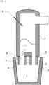
- FIG. 1 is a schematic view of a preferable embodiment according to the invention.
- the molten steel 1 is at a non-deoxidation state, and it is desirable to add an Al-containing slag modifier onto the slag 2 that covers the molten steel 1 in the ladle 3. It is not necessary to use a special facility for the addition as long as the Al-containing slag modifier can be added dispersedly onto the slag 2.
- the ladle 3 is conveyed to an RH vacuum degassing apparatus and raised by an elevating device (not shown) to immerse a rising-side immersion pipe 4 and a descending-side immersion pipe 5 into the molten steel 1 in the ladle 3.
- the Ar gas is blown into the rising-side immersion pipe 4 from an Ar gas blowing pipe 6, while an interior of a vacuum vessel 7 is exhausted by an exhaust device (not shown) to depressurize the interior of the vacuum vessel 7.
- the molten steel 1 in the ladle [[2]] 3 moves upward in the rising-side immersion pipe 4 together with the Ar gas blown from the Ar blowing pipe 6, flowed into the vacuum vessel 7, and thereafter returned to the ladle 3 through the descending-side immersion pipe 5, which is a so-called circulating stream, is formed to perform a RH vacuum degassing refining.
- decarburization reaction is advanced by the RH vacuum degassing refining.
- the concentration of the dissolved oxygen in the molten steel is measured and a metallic Al having an amount and a chemical composition required for deoxidizing the oxygen is added to the molten steel in the vacuum vessel 7 from a charging shoot 9 to deoxidize the molten steel 1.
- a flux is added to the molten steel in the vacuum vessel 7 from the charging shoot 9 to form a blocking layer 8 of the flux between the molten steel 1 and the slag 2.
- the flux being used for blocking the molten steel and the slag to prevent Ti and Al in the steel from being oxidized, is an oxide of an element having a deoxidation force equal to that of Al or Ti and is necessary not to melt at the molten steel temperature.
- the oxide includes Al 2 O 3 , MgO, and CaO as an example, and can also use a compound comprised mainly thereof such as bauxite, quicklime, magnesia brick waste, dolomite or the like.
- a given amount of a Ti source is added to the molten steel in the vacuum vessel 7 from the charging shoot 9 after the lapse of time t 3 preferably satisfying the equation (A), and the RH circulating time t 1 and the conveyance time t 2 up to the charging into the tundish are adjusted so as to satisfy the equation (1).
- the RH circulating time t 1 is preferable to be shorter, but it is desirable to previously measure the time required for the added Ti to be uniformly mixed with the molten steel and secure t 1 longer than the time.
- a molten steel of about 300 tons having a carbon concentration of 0.02 to 0.06 mass% is tapped from a converter into a ladle with an inner diameter of 3.2 m at a non-deoxidation state and subjected to a vacuum decarburization treatment in an RH vacuum degassing apparatus after the tapping to decrease the carbon concentration to not more than 0.003 mass%.
- a metallic Al is added in an amount corresponding to a dissolved oxygen concentration in the molten steel, and then a given amount of MgO is added to the molten steel in a vacuum vessel. After the lapse of time t 3 (s), a metallic Ti is added into the vacuum vessel.
- a circulating treatment is conducted in the RH vacuum degassing apparatus, and the ladle is conveyed to a tundish for continuous casting to start charging the molten steel.
- the circulating time t 1 of the molten steel after the addition of Ti in the RH vacuum degassing apparatus and the conveyance time t 2 to the tundish are varied.
- a sample for the molten steel in the tundish is taken out and analyzed.
- another analysis is also conducted on the case where Ti is added to the molten steel in the vacuum vessel without adding MgO.
- Table 1 shows the treatment conditions and the results.
- a decreasing amount ratio ⁇ Ti of the Ti concentration in the treatment conditions Nos. 1 to 25 is evaluated by a ratio to the decreasing amount of the Ti concentration in the treatment condition Nos. 26 to 30, as a comparative examples, where Ti is added to the molten steel in the vacuum vessel without adding MgO.
- the treatment condition Nos. 1 to 25 are cases where MgO is added to the molten steel in the vacuum vessel, and the decrease in the Ti concentration can be suppressed as compared to the treatment conditions Nos. 26 to 30 where MgO is not added to the molten steel in the vacuum vessel.
- the treatment condition Nos. 11 to 25 where MgO is added to the molten steel in the vacuum vessel and the treatment is performed with the circulating time of the molten steel, conveyance time and the addition amount of the flux satisfying the equation (1), the decrease in the Ti concentration can be further suppressed.
- the Ti concentration decreasing index R Ti calculated in the left side of the equation (1) is plotted in an abscissa axis and the decreasing amount ratio ⁇ Ti in an actual operation is plotted in a vertical axis to show a relation between R Ti and ⁇ Ti in FIG. 2 .
- R Ti and ⁇ Ti are well intercorrelated with each other.
- the condition of the time t 3 that satisfies the equation (A) is shown by a symbol ⁇ and the condition that does not satisfy the equation (A) is shown by ⁇ . It can be seen that, even when the Ti concentration decreasing index R Ti is the same, the decreasing amount ratio ⁇ Ti can be more decreased in the condition satisfying the equation (A).
- the Ti decreasing amount due to the oxidation with the slag can be suppressed by forming the blocking layer between the molten steel and the slag.
- This technique is applicable to steel grades required for suppressing slag-metal reaction other than the production of the Ti-containing steel.
Landscapes
- Chemical & Material Sciences (AREA)
- Engineering & Computer Science (AREA)
- Materials Engineering (AREA)
- Metallurgy (AREA)
- Organic Chemistry (AREA)
- Treatment Of Steel In Its Molten State (AREA)
Abstract
Description
- This invention relates to a method for producing a Ti-containing ultralow-carbon steel at a high Ti yield in an RH vacuum degassing apparatus.
- A Ti-containing ultralow-carbon steel is typically produced by performing a rough decarburization treatment in a primary refining furnace such as converter or the like, tapping the steel into a ladle, performing a vacuum decarburization to an ultralow carbon level in an RH vacuum degassing apparatus, adding Al to conduct a deoxidation treatment, and adding a Ti source to the resulting molten steel.
- Ti is an element having a strong oxidation power like Al. Moreover, since a Ti source is generally more expensive than an Al source, in the production of the Ti-containing steel, the molten steel in the ladle is deoxidized by adding Al, and after that, the Ti source is added, whereby the reaction of a dissolved oxygen with Ti is suppressed to secure a Ti yield.
- Although the oxygen potential of the molten steel is decreased by the deoxidation treatment with Al, when slag containing a lower oxide such as FeO, MnO or the like and having a high oxygen potential is floating above the molten steel in the ladle, the reaction between Ti in the molten steel and the lower oxide in the slag, i.e. reoxidation reaction continues to progress and forms Ti into an oxide, resulting in a decrease in the Ti yield. To suppress the reoxidation reaction, therefore, there have been proposed many methods for controlling the slag composition.
- As a countermeasure therefor, there has been adopted a method of subjecting the slag to reduction by adding a deoxidation agent (also called as a reducing agent) such as Al or the like to the slag in the ladle. For example,
Patent Literature 1 discloses a method in which a deoxidation agent is added onto the slag floating on the molten steel in a non-deoxidation state immediately after tapping from a refining furnace to a ladle to reduce FeO in the slag to suppress reoxidation of Al. - Also,
Patent Literature 2 discloses a method in which a deoxidation agent is added onto slag to suppress the reoxidation of Al and thereafter MgO source is also added to control the MgO concentration in the slag to not less than 13% to decrease the reactivity between molten steel ingredients and the slag, and increase a solid phase ratio in the slag and thus to decrease a fluidity of the slag. - Furthermore,
Patent Literature 3 discloses a method in which a TiO2 source is added to slag to control the TiO2 concentration in the slag to not less than 5% in order to suppress the reaction between SiO2 in the slag and Ti in molten steel. -
- Patent Literature 1:
JP-A-H02-30711 - Patent Literature 2:
JP-A-2015-183259 - Patent Literature 3:
JP-A-2001-355018 - In the above methods, however, the composition and amount of the slag are unclear at the addition of the material for controlling the slag composition, and thus the addition amount of the material cannot be determined or the slag composition after the addition may fall out of the desired range.
- Moreover, even when the deoxidation agent is added to the slag to decrease the lower oxide as described in
Patent Literature - The method disclosed in
Patent Literature 3 uses a VOD installation, where the lower oxide in the slag is subjected to reduction by the deoxidation of the molten steel with Al to reach an equilibrium concentration. However, the reaction between the slag and metal is slow in the RH vacuum degassing treatment, and practically, there is a problem that the lower oxide affecting the Ti yield remains or that Al needs to be added excessively to prevent such a phenomenon. - The invention is made in consideration of such circumstances, and an object thereof is to propose a method for preventing reoxidation of Ti in a molten steel in a ladle by slag and producing a Ti-containing ultralow-carbon steel stably at a high Ti yield.
- The inventors have found that the reoxidation after the addition of Ti can be suppressed by charging a flux having a higher melting point and a lower density than those of the molten steel into a vacuum vessel of an RH vacuum degassing apparatus to block the molten steel and the slag using the flux, and hence the invention has been accomplished. The invention that advantageously solves the above task is a method for producing a Ti-containing ultralow-carbon steel characterized by, in refining of a molten steel using an RH vacuum degassing apparatus, performing a deoxidation treatment of the molten steel with Al subsequent to a vacuum decarburization treatment, then adding a flux having a melting point higher than the temperature of the molten steel into a vacuum vessel in the RH vacuum degassing apparatus, and subsequently adding a Ti source.
- The method for producing a Ti-containing ultralow-carbon steel according to the invention is considered to have more preferable solving means as follows:
- (a) after the addition of the given amount of the flux, a molten steel circulating time t1 after the Ti source is added to the RH vacuum degassing apparatus, and a conveyance time t2 from the completion of the RH treatment to the start of charging the molten steel into a tundish for continuous casting are adjusted so as to satisfy the following equation (1):

- (b) the molten steel circulating time t1 and the conveyance time t2 are determined in advance, and the addition amount Wf of the flux is calculated so as to satisfy the equation (1) and added;
- (c) a time t3 after the addition of a given amount of the flux to the start of the addition of the Ti source satisfies the following equations (A) to (C):


- According to the invention, the molten steel and the slag are blocked by the flux, and the molten steel circulating time and the conveyance time from the completion of the RH treatment to the start of charging into the tundish is controlled, whereby the reoxidation of Ti in the molten steel by the slag is suppressed and the decrease in the Ti yield can be suppressed, leading to an industrial advantageous effect. The invention also has an advantage of reducing excessive use of the flux. Furthermore, the reoxidation of Ti in the molten steel by the slag can be suppressed by securing the time for the flux to float up.
-
-
FIG. 1 is a schematic view illustrating an example of the apparatus used for carrying out the invention. -
FIG. 2 is a graph showing an influence of a relation between a Ti concentration decreasing index RTi, which is calculated by the left side of the equation (1), and a Ti concentration decreasing ratio Δ Ti in an actual operation upon a circulating time t3 from an addition of a flux to an addition of a Ti source, when adopting the method according to the invention. - In order to solve the problem, the inventors have considered as follows.
- The reoxidation reaction of Ti in the molten steel by the slag is a reaction between a lower oxide in the slag and a deoxidation element in the molten steel. Accordingly, it has been considered that physically blocking the slag and the molten steel can prevent the reaction from proceeding. Thus, a flux that does not melt alone at the molten steel temperature and has a density lower than that of the molten steel is charged as a blocking material. That is, the flux is charged into the molten steel in the vacuum vessel of an RH vacuum degassing apparatus, where the flux passes through an immersion pipe of the RH vacuum degassing apparatus with the stream of the circulating molten steel and is dispersed into the molten steel in a ladle. As being low in the density as compared to the molten steel, the flux floats up in the molten steel and covers the side where the slag comes in contact with the molten steel on the surface in the ladle to block the molten steel and the slag. Also, when the flux is charged into the molten steel during a non-deoxidation treatment, a lower oxide is formed in a layer of the flux that has been charged so as to be equilibrium to oxygen potential in the molten steel, and therefore it is considered that the flux is enough to be charged after the molten steel is deoxidized with Al.
- Even though the boundary surface between the molten steel and the slag is blocked by the flux, the reaction between the molten steel ingredients and the slag ingredients is caused by infiltration and diffusion after a lapse of a long time, and also the reaction is caused after a shorter time in the case where the molten steel is agitated, whereby the effect of suppressing reoxidation will be lowered.
- At first, the behavior of a Ti concentration is investigated after Ti is added to the molten steel in the RH vacuum degassing apparatus during the production of an ultralow-carbon steel. As a comparison, an investigation is also conducted on the behavior of a Ti concentration after the molten steel and the slag are deoxidized at the tapping from the converter (hereinafter called as slag deoxidation), that is, after Ti is added to the circulating molten steel in the RH vacuum degassing apparatus with a smaller amount of the lower oxide in the slag.
- As a result, the decreasing amount of the Ti concentration is largely increased in the production of an ultralow-carbon steel, as compared to the case where the slag is subjected to the deoxidation. Accordingly, MgO is added from the vacuum vessel after the deoxidation of the molten steel with Al in the production of an ultralow-carbon steel, and then Ti is added to examine the behavior of the Ti concentration, resulting that the decreasing amount of Ti concentration is largely reduced as compared to the case of adding no MgO.
- Even when MgO is added, however, there is a large variation in the decreasing amount of the Ti concentration; in some cases, the decreasing amount of the Ti concentration is suppressed to the same extent as the case where the slag is subjected to deoxidation, while in other cases, the decreasing amount of the Ti concentration is not reduced so much. This variation may appear, in some cases, as a decrease in the Ti concentration at the completion of the RH treatment, and, in other cases, even when the Ti concentration at the completion of the RH treatment is at the same level as the case where the slag deoxidization treatment is conducted, it may appear as a decrease in the Ti concentration by the time the ladle holding the molten steel is transferred to the tundish and the molten steel is charged into the tundish after the RH treatment. This is considered to be influenced by a circulating treatment, conveyance and keeping time from the Ti addition in the RH treatment to the charging into the tundish, and hence the Ti concentration decreasing index RTi with the lapse of time after the Ti addition is examined.
- The result shows, although there is a variation, the decreasing amount of the Ti concentration tends to be larger as the time from the addition of Ti to the charging into the tundish is longer. Now, (1) the molten steel circulating time t1 (s) in the RH vacuum degassing apparatus after the addition of Ti and (2) the conveyance time t2 (s) from the end of the RH treatment to the start of charging the molten steel into the tundish for continuous casting are investigated separately. The Ti concentration decreasing index RTi is represented by the following equation (2).

- k1 donates a reaction rate constant of a Ti oxidation reaction during the circulating of the molten steel, and
- k2 donates a reaction rate constant of a Ti oxidation reaction during the conveyance from the completion of the RH treatment to the charging into the tundish.
- The reaction between Ti in the molten steel and the slag during the molten steel circulating treatment in the RH vacuum degassing apparatus is considered to be intercorrelated to a stirring power applied to the molten steel. A stirring power density ε (W/t) of the molten steel in the ladle during the molten steel circulating treatment in the RH vacuum degassing apparatus is represented by the following equation (3):

- U donates a flow speed (m/s) of the molten steel in a descending-side immersion pipe of the RH vacuum degassing apparatus,
- Q donates a circulating rate (kg/s) of the molten steel, and
- WM donates a weight (kg) of the molten steel in the ladle.
- The circulating rate Q (kg/s) of the molten steel generally uses the following equation (4):

- G donates a flow rate (Nm3/s) for a circulating gas after the addition of the Ti source in the RH vacuum degassing apparatus,
- P donates a vacuum degree (Pa) in a vessel of the RH vacuum degassing apparatus after the addition of the Ti source,
- Po donates an atmospheric pressure (101325 Pa), and
- d donates an inner diameter (m) of an immersion pipe in the RH vacuum degassing apparatus.
- The flow speed U (m/s) of the molten steel in the descending-side immersion pipe of the RH vacuum degassing apparatus is represented by the following equation (5) from the equation (4):

ρM donates a density (kg/m3) of the molten steel. - The following equation (6) is obtained by substituting the equations (4) and (5) in the equation (3):

- Also, a mass transfer rate in the circulating of the molten steel is said to be proportional to 1/3 of the stirring power density, so that the reaction rate constant k1 is determined by the following equation (7) from the equation (6):

- The reaction rate between Ti in the molten steel and the slag during the conveyance time t2 from the completion of the RH treatment to the charging into the tundish is considered to be inversely proportional to a thickness of a blocking layer between the molten steel and the slag, and the reaction rate constant k2 during the conveyance is represented by the following equation (8):

L donates a thickness (m) of the blocking layer by a flux having a melting point higher than that of the molten steel. - The thickness of the blocking layer L is represented by the following equation (9):

ρf donates an apparent density (kg/m3) of the blocking layer. - Since ρf is considered to be nearly constant when the flux is oxide, the following equation (10) is obtained by combining the equations (8) and (9):

- The Ti concentration decreasing index RTi is represented by the following equation (11), which is obtained by substituting the equations (7) and (10) in the equation (2):

A and B are constants. - In the equation (11), the constants A and B, and the Ti concentration decreasing index RTi when the slag is subjected to deoxidation are calculated by performing a regression analysis of a condition where the Ti decreasing amount is larger than that when the slag is subjected to deoxidation by varying the operation conditions, treatment conditions, and the like. The result shows that A = 190, B = 11.8 and RTi = 1800. That is, when the right side of the equation (11) is not more than 1800, the Ti decreasing amount is equal to that when the slag is subjected to deoxidation. Thus, the relation of the equation (1) is obtained.

- In the production of a Ti-containing ultralow-carbon steel with an RH vacuum degassing apparatus, therefore, the molten steel is subjected to a deoxidation treatment with Al subsequent to a vacuum decarburization treatment, and then a flux having a melting point higher than that of the molten steel is added to the vacuum vessel of the RH vacuum degassing apparatus, and thereafter a Ti source is added, whereby the Ti decreasing amount by oxidation can be reduced and the Ti-containing ultralow-carbon steel can be produced. Also, it is preferable that, after a given amount of the flux is added, the molten steel circulating time t1 in the RH treatment after the addition of Ti and the conveyance time t2 from the completion of the RH treatment to the start of charging the molten steel into the tundish for continuous casting are adjusted so as to satisfy the equation (1), whereby the Ti decreasing amount by oxidation can be made equal to that in the slag deoxidation. Furthermore, it is more preferable that the molten steel circulating time t1 and the conveyance time t2 are previously determined and the flux is added in an amount Wf satisfying the equation (1), the used amount of the flux can be minimized. For example, for the ladle of 300 tons, the molten steel circulating time t1 is usually about 180 to 480 seconds and the conveyance time t2 is, although it depends on the arrangement of the installation and the operation conditions, about 1200 to 3600 seconds. When the circulating time is too short, the Ti concentration may become non-uniform, while when the circulating time is too long, erosion of refractories, increase in the Ti decreasing amount and lowering of molten steel temperature are concerned. The lower limit of the conveyance time is dependent on the arrangement of the installation; when the conveyance time is too long, an increase in the Ti decreasing amount and the lowering of the molten steel temperature are concerned. The flux is preferably added to have a thickness of at least 3 mm such that the blocking layer is not broken even by stirring during the circulating of the molten steel. When the flux is added exceeding the thickness of 30 mm, the effect of blocking the Ti oxidation is saturated. Therefore, the thickness L of the flux forming the blocking layer preferably falls within the range of 3 to 30 mm, more preferably the range of 5 to 10 mm. Accordingly, the addition amount of the flux is, depending on the diameter of the ladle, preferably within the range of 0.3 to 3.0 kg, further preferably the range of 0.4 to 1.0 kg per 1 ton of the molten steel.
- When the Ti source is added immediately after the given amount of the flux is added, Ti, which has been added and dissolved into the molten steel, may react with the lower oxide in the slag before the flux floats up in the molten steel in the ladle and blocks the boundary surface between the molten steel and the slag. Therefore, the inventors have conceived to secure a time for the flux to float up before the addition of the Ti source.
- A floating-up speed of particles having a density smaller than that of liquid is a sum of a flow speed Uu (m/s) of the liquid in the upward and downward directions and an end speed up (m/s) of particles in a static bath. The end speed up of particles is usually represented by the following equation (D):

- ρp donates a density (kg/m3) of the flux,
- ρM donates a density (kg/m3) of the molten steel, and
- dp donates an average particle size (m) of the flux.
- In the equation (D), CD is called as a drag coefficient and depends on Reynolds (Re) number. The Re number (2 to 500) related to the movement of flux particles in the molten steel in the ladle during the RH treatment as a target of the invention is represented by CD = 10 / Re1/2 by Allen's formula. Here, the Reynolds number Re is dp • up • ρM/µM. The end speed up of the particles is the following equation (B) based on Allen's formula:

- g donates gravity acceleration (9.8 m/s2), and
- µM donates a viscosity (Pa • s) of the molten steel.
- In the ladle, the molten steel circulating in the RH vacuum degassing apparatus is considered to be a descending stream just beneath the immersion pipe at the descending side of the molten steel, while it is a rising stream at a region other than the former, so that an average rising speed Uu of the area is represented by the following equation (C):

- Q donates a circulating rate (kg/s) of the molten steel,
- S donates an area (m2) at a position of a molten surface in the ladle, and
- di donates a diameter (m) of the immersion pipe.
- When it is considered that the flux added to the molten steel in the RH vacuum vessel flows with the circulating stream, once arrives at the bottom of the ladle and rises therefrom with the rising stream of the rate Uu (m/s), a time tu (s) required for the flux particles to rise from the bottom of the ladle to the boundary surface between the molten steel and the slag is represented by the following equation (E):

the depth of the molten steel in the ladle is H (m). - Since the boundary surface between the slag and the molten steel can be sufficiently blocked by the flux after the rising time tu, it is considered that the reaction between Ti and the lower oxide in the slag can be suppressed by adding the Ti source after at least tu from the addition of the flux. Therefore, a time t3 from the addition of flux to the start of adding the Ti source is preferable to satisfy the following equation (A):

- When the circulating time t3 from the addition of the flux to the addition of the Ti source in the RH vacuum degassing apparatus is too long, the influence on the suppression of the decrease in Ti due to the reoxidation is saturated, and the treatment cost is increased. Moreover, the upper limit of t3 depends on the addition amount of the flux and the size of the apparatus, but is preferably about 60 seconds.
- The method according to the invention will be described below with reference to
FIG. 1 , which is a schematic view of a preferable embodiment according to the invention. - A
molten steel 1 andslag 2, which are obtained by decarburization refining in a converter, are tapped into aladle 3. Themolten steel 1 is at a non-deoxidation state, and it is desirable to add an Al-containing slag modifier onto theslag 2 that covers themolten steel 1 in theladle 3. It is not necessary to use a special facility for the addition as long as the Al-containing slag modifier can be added dispersedly onto theslag 2. - Thereafter, the
ladle 3 is conveyed to an RH vacuum degassing apparatus and raised by an elevating device (not shown) to immerse a rising-side immersion pipe 4 and a descending-side immersion pipe 5 into themolten steel 1 in theladle 3. The Ar gas is blown into the rising-side immersion pipe 4 from an Argas blowing pipe 6, while an interior of a vacuum vessel 7 is exhausted by an exhaust device (not shown) to depressurize the interior of the vacuum vessel 7. As the interior of the vacuum vessel 7 is depressurized, themolten steel 1 in the ladle [[2]] 3 moves upward in the rising-side immersion pipe 4 together with the Ar gas blown from theAr blowing pipe 6, flowed into the vacuum vessel 7, and thereafter returned to theladle 3 through the descending-side immersion pipe 5, which is a so-called circulating stream, is formed to perform a RH vacuum degassing refining. - At the non-deoxidation state of the molten steel, decarburization reaction is advanced by the RH vacuum degassing refining. After the decarburization is completed, the concentration of the dissolved oxygen in the molten steel is measured and a metallic Al having an amount and a chemical composition required for deoxidizing the oxygen is added to the molten steel in the vacuum vessel 7 from a charging shoot 9 to deoxidize the
molten steel 1. Thereafter, a flux is added to the molten steel in the vacuum vessel 7 from the charging shoot 9 to form ablocking layer 8 of the flux between themolten steel 1 and theslag 2. The flux, being used for blocking the molten steel and the slag to prevent Ti and Al in the steel from being oxidized, is an oxide of an element having a deoxidation force equal to that of Al or Ti and is necessary not to melt at the molten steel temperature. For example, the oxide includes Al2O3, MgO, and CaO as an example, and can also use a compound comprised mainly thereof such as bauxite, quicklime, magnesia brick waste, dolomite or the like. - Next, a given amount of a Ti source is added to the molten steel in the vacuum vessel 7 from the charging shoot 9 after the lapse of time t3 preferably satisfying the equation (A), and the RH circulating time t1 and the conveyance time t2 up to the charging into the tundish are adjusted so as to satisfy the equation (1). The RH circulating time t1 is preferable to be shorter, but it is desirable to previously measure the time required for the added Ti to be uniformly mixed with the molten steel and secure t1 longer than the time. Example
- A molten steel of about 300 tons having a carbon concentration of 0.02 to 0.06 mass% is tapped from a converter into a ladle with an inner diameter of 3.2 m at a non-deoxidation state and subjected to a vacuum decarburization treatment in an RH vacuum degassing apparatus after the tapping to decrease the carbon concentration to not more than 0.003 mass%. After the decarburization, a metallic Al is added in an amount corresponding to a dissolved oxygen concentration in the molten steel, and then a given amount of MgO is added to the molten steel in a vacuum vessel. After the lapse of time t3 (s), a metallic Ti is added into the vacuum vessel. After the addition, a circulating treatment is conducted in the RH vacuum degassing apparatus, and the ladle is conveyed to a tundish for continuous casting to start charging the molten steel. In this case, the circulating time t1 of the molten steel after the addition of Ti in the RH vacuum degassing apparatus and the conveyance time t2 to the tundish are varied. At the stage when approximately a half of the molten steel in the ladle is charged into the tundish, a sample for the molten steel in the tundish is taken out and analyzed. As a comparison, another analysis is also conducted on the case where Ti is added to the molten steel in the vacuum vessel without adding MgO.
- Table 1 shows the treatment conditions and the results. A decreasing amount ratio Δ Ti of the Ti concentration in the treatment conditions Nos. 1 to 25 is evaluated by a ratio to the decreasing amount of the Ti concentration in the treatment condition Nos. 26 to 30, as a comparative examples, where Ti is added to the molten steel in the vacuum vessel without adding MgO.
Table 1 No. RH treatment condition Time t2(s) from completion of RH treatment to start of charging into tundish Left side of equation (1) Ti decreasing amount ratio ΔTi(-) Remarks Addition amount Wf (kg) of MgO Addition amount (kg) of metallic Ti Flow rate G (Nm3/s) of circulating gas Vacuum degree P (Pa) in vessel Time t3 (s) from MgO addition to Ti addition Right side of equation (A) Circulating time ti(s) in RH after Ti addition Clause 1 Clause 2 Total RTi 1 200 161 0.033 160.0 20 31.2 360 2160 612.1 1305.0 1917.1 0.86 Invention Example 2 100 155 0.042 213.3 22 30.7 180 1320 324.7 1595.0 1919.7 0.82 Invention Example 3 300 152 0.033 240.0 21 31.3 360 3300 599.0 1329.2 1928.2 0.83 Invention Example 4 300 247 0.042 213.3 25 30.7 420 2760 757.7 1111.7 1869.4 0.80 Invention Example 5 200 249 0.042 173.3 15 30.6 300 2160 547.2 1305.0 1852.2 0.79 Invention Example 6 250 147 0.050 146.7 14 30.1 300 2820 586.6 1363.0 1949.5 0.88 Invention Example 7 150 160 0.050 240.0 38 30.3 180 1860 342.9 1498.3 1841.2 0.75 Invention Example 8 200 155 0.033 226.6 36 31.3 420 2040 701.1 1232.5 1933.6 0.81 Invention Example 9 250 160 0.042 120.0 35 30.5 300 2940 557.6 1421.0 1978.5 0.84 Invention Example 10 250 156 0.050 213.3 40 30.3 360 2640 690.2 1276.0 1966.1 0.78 Invention Example 11 250 148 0.042 173.3 25 30.6 360 2160 656.7 1044.0 1700.7 0.72 Invention Example 12 120 163 0.033 226.6 25 31.3 180 1440 300.5 1450.0 1750.4 0.71 Invention Example 13 300 151 0.033 133.3 17 31.1 420 2400 720.8 966.7 1687.5 0.70 Invention Example 14 300 254 0.042 173.3 20 30.6 240 3060 437.8 1232.5 1670.3 0.69 Invention Example 15 200 248 0.033 133.3 26 31.1 360 1740 617.9 1051.2 1669.1 0.65 Invention Example 16 300 252 0.042 240.0 25 30.8 420 2220 752.8 894.2 1647.0 0.65 Invention Example 17 300 241 0.050 173.3 21 30.2 360 2520 697.8 1015.0 1712.8 0.67 Invention Example 18 250 246 0.033 200.0 36 31.3 420 2100 705.8 1015.0 1720.8 0.67 Invention Example 19 200 150 0.042 120.0 37 30.5 300 1860 557.6 1123.7 1681.3 0.63 Invention Example 20 250 149 0.050 160.0 35 30.1 360 2100 700.7 1015.0 1715.7 0.65 Invention Example 21 250 148 0.050 186.7 37 30.2 300 2280 579.2 1102.0 1681.2 0.64 Invention Example 22 200 249 0.042 160.0 41 30.6 360 1800 659.4 1087.5 1746.9 0.67 Invention Example 23 300 149 0.033 160.0 39 31.2 360 2640 612.1 1063.3 1675.5 0.61 Invention Example 24 150 158 0.042 226.6 36 30.8 240 1500 431.5 1208.3 1639.9 0.61 Invention Example 25 250 147 0.042 200.0 33 30.7 420 1980 760.3 957.0 1717.3 0.60 Invention Example 26 0 150 0.042 186.7 - 30.7 330 1920 599.6 - - 0.96 Comparative Example 27 0 244 0.042 173.3 - 30.6 300 1980 547.2 - - 1.07 Comparative Example 28 0 246 0.033 213.3 - 30.7 360 1920 600.9 - - 1.05 Comparative Example 29 0 148 0.033 120.0 - 30.5 300 1920 515.9 - - 0.95 Comparative Example 30 0 155 0.042 186.7 - 30.7 360 1920 654.1 - - 0.99 Comparative Example - As shown in Table 1, the treatment condition Nos. 1 to 25 are cases where MgO is added to the molten steel in the vacuum vessel, and the decrease in the Ti concentration can be suppressed as compared to the treatment conditions Nos. 26 to 30 where MgO is not added to the molten steel in the vacuum vessel. In the treatment condition Nos. 11 to 25 where MgO is added to the molten steel in the vacuum vessel and the treatment is performed with the circulating time of the molten steel, conveyance time and the addition amount of the flux satisfying the equation (1), the decrease in the Ti concentration can be further suppressed. In the treatment condition Nos. 1 to 25 of Table 1, the Ti concentration decreasing index RTi calculated in the left side of the equation (1) is plotted in an abscissa axis and the decreasing amount ratio Δ Ti in an actual operation is plotted in a vertical axis to show a relation between RTi and Δ Ti in
FIG. 2 . It can be seen that RTi and Δ Ti are well intercorrelated with each other. Also, the condition of the time t3 that satisfies the equation (A) is shown by a symbol ○ and the condition that does not satisfy the equation (A) is shown by △. It can be seen that, even when the Ti concentration decreasing index RTi is the same, the decreasing amount ratio Δ Ti can be more decreased in the condition satisfying the equation (A). - According to the invention, the Ti decreasing amount due to the oxidation with the slag can be suppressed by forming the blocking layer between the molten steel and the slag. This technique is applicable to steel grades required for suppressing slag-metal reaction other than the production of the Ti-containing steel.
-
- 1
- molten steel
- 2
- slag
- 3
- ladle
- 4
- rising-side immersion pipe
- 5
- descending-side immersion pipe
- 6
- Ar gas blowing pipe
- 7
- vacuum vessel
- 8
- blocking layer
- 9
- charging shoot
Claims (4)
- A method for producing a Ti-containing ultralow-carbon steel, characterized in that,in a method for refining a molten steel using an RH vacuum degassing apparatus,a deoxidation treatment of the molten steel is performed with Al subsequent to a vacuum decarburization treatment,a flux having a melting point higher than the temperature of the molten steel is added into a vacuum vessel in the RH vacuum degassing apparatus and subsequentlya Ti source is added.
- The method for producing a Ti-containing ultralow-carbon steel according to claim 1, wherein,
after the addition of the given amount of the flux, a molten steel circulating time t1 after the Ti source is added to the RH vacuum degassing apparatus, and a conveyance time t2 from the completion of the RH treatment to the start of charging the molten steel into a tundish for continuous casting are adjusted so as to satisfy the following equation (1):
- The method for producing a Ti-containing ultralow-carbon steel according to claim 2, wherein
the molten steel circulating time t1 and the conveyance time t2 are determined in advance, and the addition amount Wf of the flux is calculated so as to satisfy the equation (1) and added. - The method for producing a Ti-containing ultralow-carbon steel according to any one of claims 1 to 3, wherein
a time t3 after the addition of a given amount of the flux to the start of the addition of the Ti source satisfies the following equations (A) to (C):


Applications Claiming Priority (2)
| Application Number | Priority Date | Filing Date | Title |
|---|---|---|---|
| JP2019045879 | 2019-03-13 | ||
| PCT/JP2019/049447 WO2020183841A1 (en) | 2019-03-13 | 2019-12-17 | Method of manufacturing titanium-containing ultra-low-carbon steel |
Publications (3)
| Publication Number | Publication Date |
|---|---|
| EP3940088A1 true EP3940088A1 (en) | 2022-01-19 |
| EP3940088A4 EP3940088A4 (en) | 2022-04-13 |
| EP3940088B1 EP3940088B1 (en) | 2023-11-22 |
Family
ID=72426380
Family Applications (1)
| Application Number | Title | Priority Date | Filing Date |
|---|---|---|---|
| EP19919173.5A Active EP3940088B1 (en) | 2019-03-13 | 2019-12-17 | Method for producing ti-containing ultralow-carbon steel |
Country Status (5)
| Country | Link |
|---|---|
| EP (1) | EP3940088B1 (en) |
| JP (1) | JP6744600B1 (en) |
| KR (1) | KR102454518B1 (en) |
| CN (1) | CN113490755A (en) |
| WO (1) | WO2020183841A1 (en) |
Families Citing this family (1)
| Publication number | Priority date | Publication date | Assignee | Title |
|---|---|---|---|---|
| JP7318822B2 (en) * | 2021-06-22 | 2023-08-01 | Jfeスチール株式会社 | Method for processing molten steel and method for manufacturing steel |
Family Cites Families (19)
| Publication number | Priority date | Publication date | Assignee | Title |
|---|---|---|---|---|
| JP2575827B2 (en) | 1988-07-18 | 1997-01-29 | 川崎製鉄株式会社 | Manufacturing method of ultra low carbon steel for continuous casting with excellent cleanliness |
| JP2674410B2 (en) * | 1992-02-10 | 1997-11-12 | 住友金属工業株式会社 | Method for producing Ti-added ultra low carbon steel |
| JP3269671B2 (en) * | 1992-10-07 | 2002-03-25 | 川崎製鉄株式会社 | Degassing and decarburizing of molten stainless steel |
| KR100328031B1 (en) * | 1997-09-11 | 2002-06-27 | 이구택 | A Refining Method for Cleanliness Lmproving of Molten Steel in Ultra-low Carbon Steel Making Process |
| JP2000239729A (en) * | 1999-02-16 | 2000-09-05 | Sumitomo Metal Ind Ltd | Manufacturing method of ultra low carbon steel with excellent cleanliness |
| JP2001355018A (en) | 2000-06-14 | 2001-12-25 | Kawasaki Steel Corp | Melting method of Ti-containing steel |
| JP2003073726A (en) * | 2001-08-29 | 2003-03-12 | Daido Steel Co Ltd | Method for producing low Ti steel |
| JP5343305B2 (en) * | 2006-03-10 | 2013-11-13 | Jfeスチール株式会社 | Method for producing Ti-containing ultra-low carbon steel slab |
| JP5315669B2 (en) * | 2007-11-05 | 2013-10-16 | Jfeスチール株式会社 | Method for refining molten steel with RH vacuum degassing equipment |
| JP5053042B2 (en) * | 2007-11-07 | 2012-10-17 | 新日本製鐵株式会社 | Continuous casting method of ultra-low carbon steel |
| KR101159928B1 (en) * | 2009-11-27 | 2012-06-25 | 현대제철 주식회사 | Vaccum refining method of ultra low carbon steel |
| CN102031453A (en) * | 2010-10-26 | 2011-04-27 | 攀钢集团钢铁钒钛股份有限公司 | Titaniferous alloy steel and preparation method thereof |
| CN102031452B (en) * | 2010-10-26 | 2012-06-06 | 攀钢集团钢铁钒钛股份有限公司 | Alloy steel and manufacturing method thereof |
| JP5891826B2 (en) * | 2011-02-14 | 2016-03-23 | Jfeスチール株式会社 | Desulfurization method for molten steel |
| CN102409133B (en) * | 2011-12-05 | 2013-03-27 | 攀钢集团攀枝花钢铁研究院有限公司 | Method for producing 23MnB steel by vacuum method |
| BR102012010090B1 (en) * | 2012-01-27 | 2018-12-04 | Jfe Steel Corporation | method for producing high cleaning steel |
| CN102676742A (en) * | 2012-03-27 | 2012-09-19 | 马钢(集团)控股有限公司 | Process method for reducing RH vacuum decarbonization end-point oxygen content of ultra-low-carbon steel |
| JP6040739B2 (en) * | 2012-12-05 | 2016-12-07 | 新日鐵住金株式会社 | Method for producing titanium-containing ultra-low carbon steel |
| JP6269229B2 (en) | 2014-03-25 | 2018-01-31 | 新日鐵住金株式会社 | Melting method of high clean steel |
-
2019
- 2019-12-17 CN CN201980092922.0A patent/CN113490755A/en active Pending
- 2019-12-17 EP EP19919173.5A patent/EP3940088B1/en active Active
- 2019-12-17 WO PCT/JP2019/049447 patent/WO2020183841A1/en not_active Ceased
- 2019-12-17 KR KR1020217024334A patent/KR102454518B1/en active Active
- 2019-12-17 JP JP2020516929A patent/JP6744600B1/en active Active
Also Published As
| Publication number | Publication date |
|---|---|
| CN113490755A (en) | 2021-10-08 |
| JP6744600B1 (en) | 2020-08-19 |
| WO2020183841A1 (en) | 2020-09-17 |
| EP3940088B1 (en) | 2023-11-22 |
| KR102454518B1 (en) | 2022-10-13 |
| EP3940088A4 (en) | 2022-04-13 |
| JPWO2020183841A1 (en) | 2021-03-25 |
| KR20210109597A (en) | 2021-09-06 |
Similar Documents
| Publication | Publication Date | Title |
|---|---|---|
| JP5904237B2 (en) | Melting method of high nitrogen steel | |
| EP3572534A1 (en) | Desulfurization treatment method for molten steel, and desulfurization agent | |
| JP6838419B2 (en) | Melting method of high nitrogen and low oxygen steel | |
| JP7060113B2 (en) | Method of adding Ca to molten steel | |
| EP3940088B1 (en) | Method for producing ti-containing ultralow-carbon steel | |
| JP3915386B2 (en) | Manufacturing method of clean steel | |
| EP4350012A1 (en) | Molten steel processing method and steel production method | |
| JP5433941B2 (en) | Melting method of high cleanliness bearing steel | |
| JPH0953109A (en) | Heated refining method for molten steel | |
| JP4404025B2 (en) | Melting method of low nitrogen steel | |
| JP7827229B1 (en) | Method for refining molten steel and method for producing steel | |
| JP3674422B2 (en) | Melting method of high cleanliness low carbon steel | |
| RU2840749C2 (en) | Method of molten steel processing and method of producing steel | |
| JP3736159B2 (en) | Steel manufacturing method with excellent cleanliness | |
| JP3745689B2 (en) | Manufacturing method for continuous cast slabs with excellent cleanliness | |
| JPH11293329A (en) | Method for producing ultra-low carbon Si-killed steel with excellent cleanliness | |
| JP4312068B2 (en) | Method of melting ultra-low carbon steel | |
| JP2000038614A (en) | Melting method of ultra low carbon steel with excellent cleanliness | |
| JP3277763B2 (en) | Refining method of ultra clean low carbon steel | |
| JP3282487B2 (en) | Manufacturing method of enamel steel | |
| JP3747653B2 (en) | Method for producing clean steel in RH vacuum degassing apparatus | |
| JP2003041315A (en) | Manufacturing method of high clean steel | |
| CN120225704A (en) | Ni-Cu alloy with excellent surface properties and method for producing same | |
| JPH11279678A (en) | Slabs and steel plates for cans with excellent cleanliness | |
| JP2000239732A (en) | Refining method of molten steel |
Legal Events
| Date | Code | Title | Description |
|---|---|---|---|
| STAA | Information on the status of an ep patent application or granted ep patent |
Free format text: STATUS: THE INTERNATIONAL PUBLICATION HAS BEEN MADE |
|
| PUAI | Public reference made under article 153(3) epc to a published international application that has entered the european phase |
Free format text: ORIGINAL CODE: 0009012 |
|
| STAA | Information on the status of an ep patent application or granted ep patent |
Free format text: STATUS: REQUEST FOR EXAMINATION WAS MADE |
|
| 17P | Request for examination filed |
Effective date: 20210826 |
|
| AK | Designated contracting states |
Kind code of ref document: A1 Designated state(s): AL AT BE BG CH CY CZ DE DK EE ES FI FR GB GR HR HU IE IS IT LI LT LU LV MC MK MT NL NO PL PT RO RS SE SI SK SM TR |
|
| A4 | Supplementary search report drawn up and despatched |
Effective date: 20220311 |
|
| RIC1 | Information provided on ipc code assigned before grant |
Ipc: C21C 7/00 20060101ALI20220305BHEP Ipc: C21C 7/10 20060101ALI20220305BHEP Ipc: C21C 7/076 20060101ALI20220305BHEP Ipc: C21C 7/06 20060101AFI20220305BHEP |
|
| DAV | Request for validation of the european patent (deleted) | ||
| DAX | Request for extension of the european patent (deleted) | ||
| STAA | Information on the status of an ep patent application or granted ep patent |
Free format text: STATUS: EXAMINATION IS IN PROGRESS |
|
| 17Q | First examination report despatched |
Effective date: 20220706 |
|
| GRAP | Despatch of communication of intention to grant a patent |
Free format text: ORIGINAL CODE: EPIDOSNIGR1 |
|
| STAA | Information on the status of an ep patent application or granted ep patent |
Free format text: STATUS: GRANT OF PATENT IS INTENDED |
|
| INTG | Intention to grant announced |
Effective date: 20230605 |
|
| RIN1 | Information on inventor provided before grant (corrected) |
Inventor name: MATSUDA, KENGO Inventor name: NAKAMURA, HARUKA Inventor name: ITO, TOSHIYUKI Inventor name: MURAI, TAKESHI |
|
| GRAS | Grant fee paid |
Free format text: ORIGINAL CODE: EPIDOSNIGR3 |
|
| GRAA | (expected) grant |
Free format text: ORIGINAL CODE: 0009210 |
|
| STAA | Information on the status of an ep patent application or granted ep patent |
Free format text: STATUS: THE PATENT HAS BEEN GRANTED |
|
| AK | Designated contracting states |
Kind code of ref document: B1 Designated state(s): AL AT BE BG CH CY CZ DE DK EE ES FI FR GB GR HR HU IE IS IT LI LT LU LV MC MK MT NL NO PL PT RO RS SE SI SK SM TR |
|
| REG | Reference to a national code |
Ref country code: GB Ref legal event code: FG4D |
|
| REG | Reference to a national code |
Ref country code: CH Ref legal event code: EP Ref country code: DE Ref legal event code: R096 Ref document number: 602019042126 Country of ref document: DE |
|
| REG | Reference to a national code |
Ref country code: IE Ref legal event code: FG4D |
|
| REG | Reference to a national code |
Ref country code: LT Ref legal event code: MG9D |
|
| REG | Reference to a national code |
Ref country code: NL Ref legal event code: MP Effective date: 20231122 |
|
| PG25 | Lapsed in a contracting state [announced via postgrant information from national office to epo] |
Ref country code: GR Free format text: LAPSE BECAUSE OF FAILURE TO SUBMIT A TRANSLATION OF THE DESCRIPTION OR TO PAY THE FEE WITHIN THE PRESCRIBED TIME-LIMIT Effective date: 20240223 |
|
| PG25 | Lapsed in a contracting state [announced via postgrant information from national office to epo] |
Ref country code: IS Free format text: LAPSE BECAUSE OF FAILURE TO SUBMIT A TRANSLATION OF THE DESCRIPTION OR TO PAY THE FEE WITHIN THE PRESCRIBED TIME-LIMIT Effective date: 20240322 |
|
| PG25 | Lapsed in a contracting state [announced via postgrant information from national office to epo] |
Ref country code: LT Free format text: LAPSE BECAUSE OF FAILURE TO SUBMIT A TRANSLATION OF THE DESCRIPTION OR TO PAY THE FEE WITHIN THE PRESCRIBED TIME-LIMIT Effective date: 20231122 |
|
| REG | Reference to a national code |
Ref country code: AT Ref legal event code: MK05 Ref document number: 1633905 Country of ref document: AT Kind code of ref document: T Effective date: 20231122 |
|
| PG25 | Lapsed in a contracting state [announced via postgrant information from national office to epo] |
Ref country code: NL Free format text: LAPSE BECAUSE OF FAILURE TO SUBMIT A TRANSLATION OF THE DESCRIPTION OR TO PAY THE FEE WITHIN THE PRESCRIBED TIME-LIMIT Effective date: 20231122 |
|
| PG25 | Lapsed in a contracting state [announced via postgrant information from national office to epo] |
Ref country code: AT Free format text: LAPSE BECAUSE OF FAILURE TO SUBMIT A TRANSLATION OF THE DESCRIPTION OR TO PAY THE FEE WITHIN THE PRESCRIBED TIME-LIMIT Effective date: 20231122 |
|
| PG25 | Lapsed in a contracting state [announced via postgrant information from national office to epo] |
Ref country code: ES Free format text: LAPSE BECAUSE OF FAILURE TO SUBMIT A TRANSLATION OF THE DESCRIPTION OR TO PAY THE FEE WITHIN THE PRESCRIBED TIME-LIMIT Effective date: 20231122 |
|
| PG25 | Lapsed in a contracting state [announced via postgrant information from national office to epo] |
Ref country code: NL Free format text: LAPSE BECAUSE OF FAILURE TO SUBMIT A TRANSLATION OF THE DESCRIPTION OR TO PAY THE FEE WITHIN THE PRESCRIBED TIME-LIMIT Effective date: 20231122 Ref country code: LT Free format text: LAPSE BECAUSE OF FAILURE TO SUBMIT A TRANSLATION OF THE DESCRIPTION OR TO PAY THE FEE WITHIN THE PRESCRIBED TIME-LIMIT Effective date: 20231122 Ref country code: IS Free format text: LAPSE BECAUSE OF FAILURE TO SUBMIT A TRANSLATION OF THE DESCRIPTION OR TO PAY THE FEE WITHIN THE PRESCRIBED TIME-LIMIT Effective date: 20240322 Ref country code: GR Free format text: LAPSE BECAUSE OF FAILURE TO SUBMIT A TRANSLATION OF THE DESCRIPTION OR TO PAY THE FEE WITHIN THE PRESCRIBED TIME-LIMIT Effective date: 20240223 Ref country code: ES Free format text: LAPSE BECAUSE OF FAILURE TO SUBMIT A TRANSLATION OF THE DESCRIPTION OR TO PAY THE FEE WITHIN THE PRESCRIBED TIME-LIMIT Effective date: 20231122 Ref country code: BG Free format text: LAPSE BECAUSE OF FAILURE TO SUBMIT A TRANSLATION OF THE DESCRIPTION OR TO PAY THE FEE WITHIN THE PRESCRIBED TIME-LIMIT Effective date: 20240222 Ref country code: AT Free format text: LAPSE BECAUSE OF FAILURE TO SUBMIT A TRANSLATION OF THE DESCRIPTION OR TO PAY THE FEE WITHIN THE PRESCRIBED TIME-LIMIT Effective date: 20231122 Ref country code: PT Free format text: LAPSE BECAUSE OF FAILURE TO SUBMIT A TRANSLATION OF THE DESCRIPTION OR TO PAY THE FEE WITHIN THE PRESCRIBED TIME-LIMIT Effective date: 20240322 |
|
| PG25 | Lapsed in a contracting state [announced via postgrant information from national office to epo] |
Ref country code: SE Free format text: LAPSE BECAUSE OF FAILURE TO SUBMIT A TRANSLATION OF THE DESCRIPTION OR TO PAY THE FEE WITHIN THE PRESCRIBED TIME-LIMIT Effective date: 20231122 Ref country code: RS Free format text: LAPSE BECAUSE OF FAILURE TO SUBMIT A TRANSLATION OF THE DESCRIPTION OR TO PAY THE FEE WITHIN THE PRESCRIBED TIME-LIMIT Effective date: 20231122 Ref country code: PL Free format text: LAPSE BECAUSE OF FAILURE TO SUBMIT A TRANSLATION OF THE DESCRIPTION OR TO PAY THE FEE WITHIN THE PRESCRIBED TIME-LIMIT Effective date: 20231122 Ref country code: NO Free format text: LAPSE BECAUSE OF FAILURE TO SUBMIT A TRANSLATION OF THE DESCRIPTION OR TO PAY THE FEE WITHIN THE PRESCRIBED TIME-LIMIT Effective date: 20240222 Ref country code: LV Free format text: LAPSE BECAUSE OF FAILURE TO SUBMIT A TRANSLATION OF THE DESCRIPTION OR TO PAY THE FEE WITHIN THE PRESCRIBED TIME-LIMIT Effective date: 20231122 Ref country code: HR Free format text: LAPSE BECAUSE OF FAILURE TO SUBMIT A TRANSLATION OF THE DESCRIPTION OR TO PAY THE FEE WITHIN THE PRESCRIBED TIME-LIMIT Effective date: 20231122 |
|
| REG | Reference to a national code |
Ref country code: DE Ref legal event code: R119 Ref document number: 602019042126 Country of ref document: DE |
|
| PG25 | Lapsed in a contracting state [announced via postgrant information from national office to epo] |
Ref country code: DK Free format text: LAPSE BECAUSE OF FAILURE TO SUBMIT A TRANSLATION OF THE DESCRIPTION OR TO PAY THE FEE WITHIN THE PRESCRIBED TIME-LIMIT Effective date: 20231122 |
|
| PG25 | Lapsed in a contracting state [announced via postgrant information from national office to epo] |
Ref country code: CZ Free format text: LAPSE BECAUSE OF FAILURE TO SUBMIT A TRANSLATION OF THE DESCRIPTION OR TO PAY THE FEE WITHIN THE PRESCRIBED TIME-LIMIT Effective date: 20231122 |
|
| PG25 | Lapsed in a contracting state [announced via postgrant information from national office to epo] |
Ref country code: SK Free format text: LAPSE BECAUSE OF FAILURE TO SUBMIT A TRANSLATION OF THE DESCRIPTION OR TO PAY THE FEE WITHIN THE PRESCRIBED TIME-LIMIT Effective date: 20231122 |
|
| PG25 | Lapsed in a contracting state [announced via postgrant information from national office to epo] |
Ref country code: SM Free format text: LAPSE BECAUSE OF FAILURE TO SUBMIT A TRANSLATION OF THE DESCRIPTION OR TO PAY THE FEE WITHIN THE PRESCRIBED TIME-LIMIT Effective date: 20231122 Ref country code: SK Free format text: LAPSE BECAUSE OF FAILURE TO SUBMIT A TRANSLATION OF THE DESCRIPTION OR TO PAY THE FEE WITHIN THE PRESCRIBED TIME-LIMIT Effective date: 20231122 Ref country code: RO Free format text: LAPSE BECAUSE OF FAILURE TO SUBMIT A TRANSLATION OF THE DESCRIPTION OR TO PAY THE FEE WITHIN THE PRESCRIBED TIME-LIMIT Effective date: 20231122 Ref country code: IT Free format text: LAPSE BECAUSE OF FAILURE TO SUBMIT A TRANSLATION OF THE DESCRIPTION OR TO PAY THE FEE WITHIN THE PRESCRIBED TIME-LIMIT Effective date: 20231122 Ref country code: EE Free format text: LAPSE BECAUSE OF FAILURE TO SUBMIT A TRANSLATION OF THE DESCRIPTION OR TO PAY THE FEE WITHIN THE PRESCRIBED TIME-LIMIT Effective date: 20231122 Ref country code: DK Free format text: LAPSE BECAUSE OF FAILURE TO SUBMIT A TRANSLATION OF THE DESCRIPTION OR TO PAY THE FEE WITHIN THE PRESCRIBED TIME-LIMIT Effective date: 20231122 Ref country code: CZ Free format text: LAPSE BECAUSE OF FAILURE TO SUBMIT A TRANSLATION OF THE DESCRIPTION OR TO PAY THE FEE WITHIN THE PRESCRIBED TIME-LIMIT Effective date: 20231122 |
|
| REG | Reference to a national code |
Ref country code: CH Ref legal event code: PL |
|
| PG25 | Lapsed in a contracting state [announced via postgrant information from national office to epo] |
Ref country code: LU Free format text: LAPSE BECAUSE OF NON-PAYMENT OF DUE FEES Effective date: 20231217 |
|
| PG25 | Lapsed in a contracting state [announced via postgrant information from national office to epo] |
Ref country code: MC Free format text: LAPSE BECAUSE OF FAILURE TO SUBMIT A TRANSLATION OF THE DESCRIPTION OR TO PAY THE FEE WITHIN THE PRESCRIBED TIME-LIMIT Effective date: 20231122 |
|
| REG | Reference to a national code |
Ref country code: BE Ref legal event code: MM Effective date: 20231231 |
|
| PG25 | Lapsed in a contracting state [announced via postgrant information from national office to epo] |
Ref country code: MC Free format text: LAPSE BECAUSE OF FAILURE TO SUBMIT A TRANSLATION OF THE DESCRIPTION OR TO PAY THE FEE WITHIN THE PRESCRIBED TIME-LIMIT Effective date: 20231122 Ref country code: LU Free format text: LAPSE BECAUSE OF NON-PAYMENT OF DUE FEES Effective date: 20231217 |
|
| PLBE | No opposition filed within time limit |
Free format text: ORIGINAL CODE: 0009261 |
|
| STAA | Information on the status of an ep patent application or granted ep patent |
Free format text: STATUS: NO OPPOSITION FILED WITHIN TIME LIMIT |
|
| REG | Reference to a national code |
Ref country code: IE Ref legal event code: MM4A |
|
| PG25 | Lapsed in a contracting state [announced via postgrant information from national office to epo] |
Ref country code: DE Free format text: LAPSE BECAUSE OF NON-PAYMENT OF DUE FEES Effective date: 20240702 Ref country code: IE Free format text: LAPSE BECAUSE OF NON-PAYMENT OF DUE FEES Effective date: 20231217 |
|
| PG25 | Lapsed in a contracting state [announced via postgrant information from national office to epo] |
Ref country code: BE Free format text: LAPSE BECAUSE OF NON-PAYMENT OF DUE FEES Effective date: 20231231 |
|
| PG25 | Lapsed in a contracting state [announced via postgrant information from national office to epo] |
Ref country code: FR Free format text: LAPSE BECAUSE OF NON-PAYMENT OF DUE FEES Effective date: 20240122 |
|
| PG25 | Lapsed in a contracting state [announced via postgrant information from national office to epo] |
Ref country code: CH Free format text: LAPSE BECAUSE OF NON-PAYMENT OF DUE FEES Effective date: 20231231 |
|
| GBPC | Gb: european patent ceased through non-payment of renewal fee |
Effective date: 20240222 |
|
| PG25 | Lapsed in a contracting state [announced via postgrant information from national office to epo] |
Ref country code: SI Free format text: LAPSE BECAUSE OF FAILURE TO SUBMIT A TRANSLATION OF THE DESCRIPTION OR TO PAY THE FEE WITHIN THE PRESCRIBED TIME-LIMIT Effective date: 20231122 |
|
| 26N | No opposition filed |
Effective date: 20240823 |
|
| PG25 | Lapsed in a contracting state [announced via postgrant information from national office to epo] |
Ref country code: SI Free format text: LAPSE BECAUSE OF FAILURE TO SUBMIT A TRANSLATION OF THE DESCRIPTION OR TO PAY THE FEE WITHIN THE PRESCRIBED TIME-LIMIT Effective date: 20231122 Ref country code: IE Free format text: LAPSE BECAUSE OF NON-PAYMENT OF DUE FEES Effective date: 20231217 Ref country code: FR Free format text: LAPSE BECAUSE OF NON-PAYMENT OF DUE FEES Effective date: 20240122 Ref country code: DE Free format text: LAPSE BECAUSE OF NON-PAYMENT OF DUE FEES Effective date: 20240702 Ref country code: CH Free format text: LAPSE BECAUSE OF NON-PAYMENT OF DUE FEES Effective date: 20231231 Ref country code: BE Free format text: LAPSE BECAUSE OF NON-PAYMENT OF DUE FEES Effective date: 20231231 |
|
| PG25 | Lapsed in a contracting state [announced via postgrant information from national office to epo] |
Ref country code: GB Free format text: LAPSE BECAUSE OF NON-PAYMENT OF DUE FEES Effective date: 20240222 |
|
| PG25 | Lapsed in a contracting state [announced via postgrant information from national office to epo] |
Ref country code: GB Free format text: LAPSE BECAUSE OF NON-PAYMENT OF DUE FEES Effective date: 20240222 |
|
| PG25 | Lapsed in a contracting state [announced via postgrant information from national office to epo] |
Ref country code: FI Free format text: LAPSE BECAUSE OF FAILURE TO SUBMIT A TRANSLATION OF THE DESCRIPTION OR TO PAY THE FEE WITHIN THE PRESCRIBED TIME-LIMIT Effective date: 20231122 |
|
| PG25 | Lapsed in a contracting state [announced via postgrant information from national office to epo] |
Ref country code: CY Free format text: LAPSE BECAUSE OF FAILURE TO SUBMIT A TRANSLATION OF THE DESCRIPTION OR TO PAY THE FEE WITHIN THE PRESCRIBED TIME-LIMIT; INVALID AB INITIO Effective date: 20191217 |
|
| PG25 | Lapsed in a contracting state [announced via postgrant information from national office to epo] |
Ref country code: HU Free format text: LAPSE BECAUSE OF FAILURE TO SUBMIT A TRANSLATION OF THE DESCRIPTION OR TO PAY THE FEE WITHIN THE PRESCRIBED TIME-LIMIT; INVALID AB INITIO Effective date: 20191217 |
|
| PGFP | Annual fee paid to national office [announced via postgrant information from national office to epo] |
Ref country code: TR Payment date: 20251225 Year of fee payment: 7 |