EP3938683B1 - Getriebe mit einem schmieröl verteilerteil - Google Patents
Getriebe mit einem schmieröl verteilerteil Download PDFInfo
- Publication number
- EP3938683B1 EP3938683B1 EP20707179.6A EP20707179A EP3938683B1 EP 3938683 B1 EP3938683 B1 EP 3938683B1 EP 20707179 A EP20707179 A EP 20707179A EP 3938683 B1 EP3938683 B1 EP 3938683B1
- Authority
- EP
- European Patent Office
- Prior art keywords
- gear unit
- baffle plate
- unit according
- lubricating oil
- collection region
- Prior art date
- Legal status (The legal status is an assumption and is not a legal conclusion. Google has not performed a legal analysis and makes no representation as to the accuracy of the status listed.)
- Active
Links
Images

Classifications
-
- F—MECHANICAL ENGINEERING; LIGHTING; HEATING; WEAPONS; BLASTING
- F16—ENGINEERING ELEMENTS AND UNITS; GENERAL MEASURES FOR PRODUCING AND MAINTAINING EFFECTIVE FUNCTIONING OF MACHINES OR INSTALLATIONS; THERMAL INSULATION IN GENERAL
- F16H—GEARING
- F16H57/00—General details of gearing
- F16H57/04—Features relating to lubrication or cooling or heating
- F16H57/042—Guidance of lubricant
- F16H57/0421—Guidance of lubricant on or within the casing, e.g. shields or baffles for collecting lubricant, tubes, pipes, grooves, channels or the like
- F16H57/0423—Lubricant guiding means mounted or supported on the casing, e.g. shields or baffles for collecting lubricant, tubes or pipes
-
- F—MECHANICAL ENGINEERING; LIGHTING; HEATING; WEAPONS; BLASTING
- F16—ENGINEERING ELEMENTS AND UNITS; GENERAL MEASURES FOR PRODUCING AND MAINTAINING EFFECTIVE FUNCTIONING OF MACHINES OR INSTALLATIONS; THERMAL INSULATION IN GENERAL
- F16H—GEARING
- F16H57/00—General details of gearing
- F16H57/04—Features relating to lubrication or cooling or heating
- F16H57/0457—Splash lubrication
-
- F—MECHANICAL ENGINEERING; LIGHTING; HEATING; WEAPONS; BLASTING
- F16—ENGINEERING ELEMENTS AND UNITS; GENERAL MEASURES FOR PRODUCING AND MAINTAINING EFFECTIVE FUNCTIONING OF MACHINES OR INSTALLATIONS; THERMAL INSULATION IN GENERAL
- F16H—GEARING
- F16H57/00—General details of gearing
- F16H57/04—Features relating to lubrication or cooling or heating
- F16H57/0467—Elements of gearings to be lubricated, cooled or heated
- F16H57/0469—Bearings or seals
- F16H57/0471—Bearing
-
- F—MECHANICAL ENGINEERING; LIGHTING; HEATING; WEAPONS; BLASTING
- F16—ENGINEERING ELEMENTS AND UNITS; GENERAL MEASURES FOR PRODUCING AND MAINTAINING EFFECTIVE FUNCTIONING OF MACHINES OR INSTALLATIONS; THERMAL INSULATION IN GENERAL
- F16H—GEARING
- F16H57/00—General details of gearing
- F16H57/04—Features relating to lubrication or cooling or heating
- F16H57/0408—Exchange, draining or filling of transmission lubricant
-
- F—MECHANICAL ENGINEERING; LIGHTING; HEATING; WEAPONS; BLASTING
- F16—ENGINEERING ELEMENTS AND UNITS; GENERAL MEASURES FOR PRODUCING AND MAINTAINING EFFECTIVE FUNCTIONING OF MACHINES OR INSTALLATIONS; THERMAL INSULATION IN GENERAL
- F16H—GEARING
- F16H57/00—General details of gearing
- F16H57/04—Features relating to lubrication or cooling or heating
- F16H57/048—Type of gearings to be lubricated, cooled or heated
- F16H57/0493—Gearings with spur or bevel gears
- F16H57/0495—Gearings with spur or bevel gears with fixed gear ratio
Definitions
- the invention relates to a transmission with housing.
- the invention is therefore based on the object of achieving the most efficient use of lubricating oil possible.
- the object is achieved in the transmission according to the features specified in claim 1.
- the transmission is designed with a housing and with a distributor part that can be supplied with lubricating oil through a recess in the housing, in particular in a housing part of the housing or in a cover part of the housing, wherein the distributor part has a collecting area and supply channels connected to the collecting area, by means of which lubricating oil can be supplied to bearings of the transmission.
- the lubricating oil can be used efficiently, i.e. as little lubricating oil as possible is required in the gearbox and sufficient lubrication can still be achieved, especially when the oil level is as permanently low as possible. In this way, losses can be reduced.
- the lubricating oil is filled into the gearbox through the recess. When filling, the lubricating oil is guided along the baffle plate into a collection area and from there to the designated lubrication points, from which the gearbox bearings are supplied with lubricating oil.
- a baffle plate is arranged between the recess and the collection area, in particular wherein the flat baffle plate is arranged in a plane which intersects the recess, in particular halves it, in particular so that lubricating oil filled into the gear through the recess flows along both sides of the baffle plate into the collection area.
- the baffle plate is fixed by means of a height adjustment to a retaining plate which is attached to the housing, in particular to the cover part of the housing, of the gearbox, in particular screwed on by means of fastening screws.
- the advantage here is that the distributor part can be adapted to the diameter of the selected gear wheel.
- the height adjustment comprises several holes provided in the baffle plate and a fixing element protruding through one of the holes, wherein the holes are each spaced at different distances from the cover part, in particular wherein the fixing element protrudes through a hole through the holding plate.
- the distributor part is connected to the baffle plate, in particular firmly connected, in particular materially connected.
- the advantage here is that the distributor part is held by the baffle plate, which is held by the retaining plate, which is held by the cover part.
- the oil flowing off the baffle plate can be directed in a targeted manner into the collection area and from there via the supply channels to the lubrication points, in particular bearings.
- the recess can be closed by a closure part, in particular by a closure screw.
- a closure part in particular by a closure screw.
- the flat baffle plate is arranged in a plane which is aligned parallel to the axis of rotation of the gear, in particular in such a way that, depending on the direction of rotation of the gear, lubricating oil thrown off the gear impacts on a respective side of the baffle plate.
- the advantage here is that when filling the lubricating oil, a first part flows down the front of the baffle plate and a second part flows down the rear side of the baffle plate into the collection area. This allows a certain amount of guidance of the lubricating oil flowing in through the recess.
- the baffle plate is connected, in particular welded, to the distributor part, in particular the collector area, within the collector area. It is advantageous that the distributor part is held by the baffle plate.
- the collection area is trough-shaped and/or has such a side wall and the distributor part, in particular the collection area, is arranged so close to the gear that the lubricating oil carried along by the gear during its rotational movement, in particular at a first temperature, collects so high on the side wall that lubricating oil flows over the side wall into the collection area.
- the side wall acts as a scraper when the oil is cold.
- no lubricating oil collects so high on the side wall that it flows over the side wall into the collection area, in particular wherein the lubricating oil has a higher viscosity at the first temperature than at the second temperature.
- the side wall is aligned parallel to the axis of rotation of the gear.
- the advantage here is that the side wall acts as a scraper that is aligned transversely to the gear teeth.
- the gear has tooth edges 6 which are connected in a rotationally fixed manner to shafts, wherein the shafts are rotatably mounted by means of bearings accommodated in a housing part 1.
- the gearbox is partially filled with lubricating oil, the amount of lubricating oil is so small that only the teeth of the largest gear are immersed in the oil sump.
- a retaining plate 22 for the oil supply is attached to the inside of the cover part 9.
- a baffle plate 4 is attached to the retaining plate 22 and is adjustable in height.
- the height adjustment is achieved by a hole pattern, in particular a series of holes, in the impact plate 4, whereby a fixing element 20, in particular a screw with a nut, fixes the impact plate 4.
- the fixing element 20 protrudes through the hole selected.
- the baffle plate 4 is connected, in particular welded, to a distributor part at its end region facing away from the holding plate 22.
- the distributor part has a collection region 3 which catches the oil flowing down the baffle plate 4 on both sides when it is filled with oil through the recess.
- the collected oil is fed into feed channels 5 and 7, which lead the oil directly or indirectly to bearings of rotatably mounted gear parts.
- the bearing channel 5 leads to a housing pocket formed in the housing part 1, from which the oil is led through holes to bearings accommodated in the housing part 1.
- the feed channel 7 leads oil to the bearings of the input shaft.
- the sealing plug 2 is inserted into the recess and the cover part 9 is sealed again.
- the collection area 3 of the distributor part is bordered by a side wall 23, which can preferably be produced as a bent-up tab area.
- the height of this side wall 23 is so low and the distributor part, in particular the collection area 3, is arranged so close to the gear 6 that the oil carried along by the gear 6 during the rotational movement, in particular at the start of operation when temperatures are still low, is scraped off the side wall 23 and thus oil is scraped off and/or flows into the distributor part.
- the oil film pulled up from the oil sump and carried along by the rotating gear 6 is so thick that the side wall 23 swells up the oil film to such an extent that the oil even flows over the side wall 23 into the collection area 3.
- the side wall 23 therefore acts like a scraper when the oil is cold.
- the distance between the distributor part, in particular the side wall 23, and the tip circle of the gear teeth of the gear 6 is designed to be correspondingly small.
- the thickness of the oil film that is carried along decreases and the side wall 23 no longer acts as a scraper or only acts to a small extent.
- the oil carried along by the gear 6 is thrown off the gear 6 during the rotational movement.
- the baffle plate 4 then catches a portion of the oil thrown off the gear 6 during its rotational movement and directs this collected oil into the collection area 3, from where the oil is then fed via the feed channels (5, 7) to the parts of the transmission that are to be supplied with oil.
- baffle plate 4 On the baffle plate 4, spaced apart web areas are formed which protrude from one another towards the distributor part and are designed as spacing areas. The web areas protrude into the collection area and/or support the baffle plate 4 on the collection area 3, in particular, the baffle plate 4 is spaced apart from the distributor part having the collecting channel 3 by the web areas.
- the closure plug 2 is designed as a closure screw which is screwed into a thread of the cover part.
Landscapes
- Engineering & Computer Science (AREA)
- General Engineering & Computer Science (AREA)
- Mechanical Engineering (AREA)
- General Details Of Gearings (AREA)
- Gear Transmission (AREA)
- Gears, Cams (AREA)
Description
- Die Erfindung betrifft ein Getriebe mit Gehäuse.
- Es ist allgemein bekannt, dass ein Getriebe innerhalb seines Gehäuses Schmieröl aufweist. Allerdings entsteht beim Bewegen des Schmieröls mittels drehender Verzahnungsteile des Getriebes Verlustwärme.
- Aus der
CN 101 463 896 A ist als nächstliegender Stand der Technik ein Getriebe bekannt. - Aus der
US 2013/283955 A1 ist eine Öl-Schmiervorrichtung mit Sammelschiene bekannt. - Aus der
EP 2 148 114 A1 ist eine Schmiervorrichtung bekannt. - Aus der
CN 205 089 955 U ist ein Getriebe mit Ölschmierung bekannt. - Aus der
WO 2014/108250 A1 ist eine Anordnung zum Schmieren von zwei vertikalen Getriebewellen bekannt. - Aus der
WO 2018/100259 A1 ist eine Anordnung zum Leiten von Schmieröl innerhalb einer Hohlwelle eines Getriebes bekannt. - Aus der
JP H04 277360 A - Der Erfindung liegt daher die Aufgabe zugrunde, eine möglichst effiziente Nutzung von Schmieröl zu erreichen.
- Erfindungsgemäß wird die Aufgabe bei dem Getriebe nach den in Anspruch 1 angegebenen Merkmalen gelöst.
- Wichtige Merkmale der Erfindung bei dem Getriebe sind, dass das Getriebe mit Gehäuse ausgeführt ist und mit einem durch eine Ausnehmung im Gehäuse, insbesondere in einem Gehäuseteil des Gehäuses oder in einem Deckelteil des Gehäuses, mit Schmieröl beaufschlagbaren Verteilerteil,
wobei das Verteilerteil einen Sammelbereich und mit dem Sammelbereich verbundene Zuleitrinnen aufweist, mittels derer Schmieröl zu Lagern des Getriebes hinleitbar ist. - Von Vorteil ist dabei, dass eine effiziente Nutzung des Schmieröls erreichbar ist, also möglichst wenig Schmieröl im Getriebe notwendig ist und trotzdem eine ausreichende Schmierung erreichbar ist, insbesondere bei möglichst dauerhaft niedrigem Ölstand. Auf diese Weise sind die Verluste verringerbar. Erfindungsgemäß wird das Schmieröl durch die Ausnehmung ins Getriebe eingefüllt. Beim Einfüllen wird das Schmieröl am Prallblech entlang in einen Sammelbereich geleitet und von dort zu den vorgesehenen Schmierstellen, von denen aus Lager des Getriebes mit Schmieröl versorgt werden.
- Somit ist die Befüllung mit Schmieröl bei Inbetriebnahme des Getriebes ausführbar.
- Erfindungsgemäß ist ein Prallblech zwischen der Ausnehmung und dem Sammelbereich angeordnet, insbesondere wobei das eben ausgeführte Prallblech in einer Ebene angeordnet ist, welche die Ausnehmung schneidet, insbesondere halbiert, insbesondere so dass durch die Ausnehmung ins Getriebe eingefülltes Schmieröl an beiden Seiten des Prallblechs entlang in den Sammelbereich fließt. Von Vorteil ist dabei, dass im Betrieb bei hohen Temperaturen herangeschleudertes Schmieröl aufgefangen wird und in den Sammelbereich abgeleitet und danach genutzt wird.
- Erfindungsgemäß ist das Prallblech mittels einer Höhenverstellung an einem Halteblech fixiert, welches am Gehäuse, insbesondere an dem Deckelteil des Gehäuses, des Getriebes befestigt ist, insbesondere mittels Befestigungsschrauben angeschraubt ist. Von Vorteil ist dabei, dass das Verteilerteil an den Durchmesser des jeweils gewählten Zahnrads anpassbar ist.
- Bei einer vorteilhaften Ausgestaltung umfasst die Höhenverstellung mehrere im Prallblech vorgesehene Löcher und ein durch eines der Löcher hindurchragendes Fixierelement, wobei die Löcher jeweils unterschiedlich weit beabstandet sind vom Deckelteil, insbesondere wobei das Fixierelement durch ein durch das Halteblech durchgehendes Loch hindurchragt. Von Vorteil ist dabei, dass eine einfache Verbindung des Prallblechs mit dem Halteblech erreichbar ist, wobei eine Höhenverstellung vorgesehen ist.
- Bei einer vorteilhaften Ausgestaltung ist das Verteilerteil mit dem Prallblech verbunden, insbesondere fest verbunden, insbesondere stoffschlüssig verbunden. Von Vorteil ist dabei, dass das Verteilerteil vom Prallblech haltbar ist, das vom Halteblech haltbar ist, das vom Deckelteil gehalten wird. Außerdem ist somit das am Prallblech abfließende Öl zielgerichtet in den Sammelbereich führbar und von dort über die Zuleitungsrinnen zu den Schmierstellen, insbesondere Lagerungen.
- Bei einer vorteilhaften Ausgestaltung ist die Ausnehmung durch ein Verschlussteil, insbesondere durch eine Verschlussschraube, verschließbar. Von Vorteil ist dabei, dass nur bei Inbetriebnahme der Innenraum mit der Umgebung korrespondiert.
- Bei einer vorteilhaften Ausgestaltung ist das eben ausgeführte Prallblech in einer Ebene angeordnet, welche parallel zur Drehachse des Zahnrads ausgerichtet ist, insbesondere so, dass abhängig von der Drehrichtung des Zahnrads vom Zahnrad abgeschleudertes Schmieröl auf eine jeweilige Seite des Prallblechs aufprallt. Von Vorteil ist dabei, dass beim Einfüllen des Schmieröls ein erster Teil an der Vorderseite des Prallblechs und ein zweiter Teil an der hinteren Seite des Prallblechs herunterfließt in den Sammelbereich. Somit ist eine gewisse Führung des durch die Ausnehmung einströmenden Schmieröls erreichbar.
- Bei einer vorteilhaften Ausgestaltung ist das Prallblech innerhalb des Sammelbereichs mit dem Verteilerteil, insbesondere Sammelbereich, verbunden, insbesondere schweißverbunden. Von Vorteil ist dabei, dass das Verteilerteil über das Prallblech gehalten ist.
- Bei einer vorteilhaften Ausgestaltung ist der Sammelbereich wannenförmig ausgeführt und/oder weist eine derartige Seitenwand auf und das Verteilerteil, insbesondere der Sammelbereich, ist derart nahe am Zahnrad angeordnet, dass das vom Zahnrad bei dessen Drehbewegung mitgenommene Schmieröl, insbesondere bei einer ersten Temperatur, sich derart hoch an der Seitenwand ansammelt, dass Schmieröl über die Seitenwand in den Sammelbereich fließt. Von Vorteil ist dabei, dass die Seitenwand bei kaltem Öl als Abstreifer fungiert.
- Bei einer vorteilhaften Ausgestaltung sammelt sich bei einer zweiten Temperatur, welche höher ist als die erste Temperatur, kein Schmieröl derart hoch an der Seitenwand an, dass es über die Seitenwand in den Sammelbereich fließt, insbesondere wobei das Schmieröl bei der ersten Temperatur eine höhere Viskosität aufweist als bei der zweiten Temperatur. Von Vorteil ist dabei, dass bei warmem Schmieröl dieses keinen dicken Ölfilm um das drehende Zahnrad herum bildet, sondern das Schmieröl abgeschleudert wird zum Prallblech.
- Bei einer vorteilhaften Ausgestaltung ist die Seitenwand parallel zur Drehachse des Zahnrads ausgerichtet. Von Vorteil ist dabei, dass die Seitenwand als quer zur Verzahnung des Zahnrads gerichteter Abstreifer fungiert.
- Weitere Vorteile ergeben sich aus den Unteransprüchen. Änderungen oder Kombinationsmöglichkeiten von Merkmalen können vorgenommen werden, ohne vom Schutzumfang der Ansprüche abzuweichen.
- Die Erfindung wird nun anhand von schematischen Abbildungen näher erläutert:
- In der
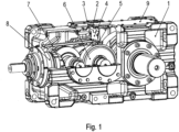
Figur 1 ist ein erfindungsgemäßes Getriebe mit Ölzuführung angeschnitten dargestellt. - In der
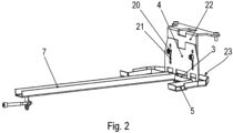
Figur 2 ist die Ölzuführung in Schrägansicht aus einer ersten Blickrichtung dargestellt - In der
Figur 3 ist die Ölzuführung aus einer anderen Blickrichtung dargestellt. - Wie in den Figuren gezeigt, weist das Getriebe drehfest mit Wellen verbundene Zahnränder 6 auf, wobei die Wellen mittels in einem Gehäuseteil 1 aufgenommener Lager drehbar gelagert sind.
- Das Getriebe ist zwar mit Schmieröl teilweise befüllt, jedoch ist die Schmierölmenge derart gering, dass nur die Verzahnung des größten Zahnrades in den Ölsumpf eintaucht.
- Bei Inbetriebnahme wird zur Sicherstellung der beim Betrieb notwendigen Schmierung Öl in das Getriebe eingefüllt.
- Dies erfolgt durch Entfernen eines Verschlussstopfens 2, durch den in einem Deckelteil 9 eine Ausnehmung verschließbar ist. Bei Inbetriebnahme wird also das Schmieröl durch die Ausnehmung in den Innenraumbereich gegossen.
- An der Innenseite des Deckelteils 9 ist ein Halteblech 22 der Ölzuführung befestigt. Höhenverstellbar ist am Halteblech 22 ein Prallblech 4 befestigt.
- Die Höhenverstellung ist hierbei durch ein Lochraster, insbesondere eine Reihe von Löchern, im Prallblech 4 realisiert, wobei ein Fixierelement 20, insbesondere Schraube mit Mutter, das Prallblech 4 fixiert. Das Fixierelement 20 ragt durch das jeweils gewählte Loch hindurch. Mittels der auf die Schaube des Fixierelements 20 aufgeschraubten Mutter wird das Prallblech 4 gegen das Halteblech 22 gedrückt und dieses somit gegen den Schraubenkopf der Schraube des Fixierelements 20. Auf diese Weise ist also das Prallblech 4 gegen das Halteblech 22 geklemmt und mittels des durch das Prallblech 4 durchgehenden Fixierelements formschlüssig gesichert.
- Das Prallblech 4 ist an seinem vom Halteblech 22 abgewandten Endbereich mit einem Verteilerteil verbunden, insbesondere schweißverbunden. Das Verteilerteil weist einen Sammelbereich 3 auf, welcher beim durch die Ausnehmung vorgenommenen Befüllen mit Öl das am Prallblech 4 beidseitig, herabfließende Öl auffängt.
- Das aufgefangene Öl wird in Zuleitrinnen 5 und 7 geleitet, welche das Öl zu Lagern von drehbar gelagerten Verzahnungsteilen direkt oder indirekt führen. Beispielsweise führt die Lagerrinne 5 zu einer im Gehäuseteil 1 ausgeformten Gehäusetasche, von der das Öl durch Bohrungen zu im Gehäuseteil 1 aufgenommenen Lagern geführt wird. Weiter beispielsweise führt die Zuleitrinne 7 Öl zu den Lagern der eintreibenden Welle.
- Bei Betrieb wird der Verschlussstopfen 2 in die Ausnehmung gesteckt und somit das Deckelteil 9 wieder abgedichtet.
- Der Sammelbereich 3 des Verteilerteils ist berandet von einer Seitenwand 23, die vorzugsweise als hochgebogener Laschenbereich herstellbar ist. Die Höhe dieser Seitenwand 23 ist derart gering und das Verteilerteil, insbesondere der Sammelbereich 3, ist derart nah an dem Zahnrad 6 angeordnet, dass das bei der Drehbewegung vom Zahnrad 6 mitgenommene Öl, insbesondere zu Beginn des Betriebs bei noch tiefen Temperaturen, an der Seitenwand 23 abgestreift wird und somit Öl in das Verteilerteil abgestreift wird und/oder einströmt.
- Denn bei tiefen Temperaturen ist das Öl hochviskos. Daher ist der vom drehenden Zahnrad 6 aus dem Ölsumpf hochgezogene und mitgeschleppte Ölfilm derart dick, dass die Seitenwand 23 den Ölfilm derart aufbauscht, dass das Öl sogar über die Seitenwand 23 in den Sammelbereich 3 einfließt. Die Seitenwand 23 wirkt also bei kaltem Öl wie ein Abstreifer. Der Abstand zwischen dem Verteilerteil, insbesondere der Seitenwand 23, und dem Kopfkreis der Verzahnung des Zahnrads 6 ist entsprechend gering ausgeführt.
- Bei im Betrieb erwärmtem Öl nimmt die Dicke des mitgeschleppten Ölfilms ab und die Seitenwand 23 wirkt nicht mehr oder nur noch geringfügig als Abstreifer. Allerdings wird das vom Zahnrad 6 mitgenommene Öl bei der Drehbewegung vom Zahnrad 6 abgeschleudert. Das Prallblech 4 fängt dann einen Teil des vom Zahnrad 6 bei dessen Drehbewegung abgeschleuderten Öls auf und leitet dieses aufgefangene Öl in den Sammelbereich 3, von wo das Öl dann über die Zuleitrinnen (5, 7) den mit Öl zu versorgenden Stellen des Getriebes zugeleitet wird.
- Am Prallblech 4 zum Verteilerteil hin hervorragende, voneinander beabstandete Stegbereiche ausgeformt sind, die als Beabstandungsbereiche ausgebildet sind. Die Stegbereiche ragen in den Sammelbereich hinein und/oder stützen das Prallblech 4 am Sammelbereich 3 ab,
insbesondere wobei mit den Stegbereichen das Prallblech 4 vom die Sammelrinne 3 aufweisenden Verteilerteil beabstandet ist. - Bei weiteren erfindungsgemäßen Ausführungsbeispielen wird der Verschlussstopfen 2 als Verschlussschraube ausgeführt, welche in ein Gewinde des Deckelteils eingeschraubt ist.
-
- 1 Gehäuseteil
- 2 Verschlussstopfen
- 3 Sammelbereich
- 4 Prallblech
- 5 Zuleitrinne
- 6 Zahnrad
- 7 Zuleitrinne
- 8 Lager der eintreibenden Welle
- 9 Deckelteil
- 20 Fixierelement, insbesondere Schraube mit Mutter
- 21 durchgehende Ausnehmungen, insbesondere Lochraster
- 22 Halteblech
- 23 Seitenwand der Sammelbereichs 3
Claims (15)
- Getriebe mit Gehäuse und mit einem durch eine Ausnehmung im Gehäuse, insbesondere in einem Gehäuseteil (1) des Gehäuses oder in einem Deckelteil (9) des Gehäuses, mit Schmieröl beaufschlagbaren Verteilerteil,wobei das Verteilerteil einen Sammelbereich (3) und mit dem Sammelbereich (3) verbundene Zuleitrinnen (5, 7) aufweist, mittels derer Schmieröl zu Lagern (8) des Getriebes hinleitbar ist,dadurch gekennzeichnet, dassein Prallblech (4) zwischen der Ausnehmung und dem Sammelbereich (3) angeordnet ist,das Prallblech (4) mittels einer Höhenverstellung an einem Halteblech (22) fixiert ist, welches am Gehäuse des Getriebes befestigt ist.
- Getriebe nach Anspruch 1,
dadurch gekennzeichnet, dassdas eben ausgeführte Prallblech (4) in einer Ebene angeordnet ist, welche die Ausnehmung schneidet, insbesondere halbiert,insbesondere so dass durch die Ausnehmung ins Getriebe eingefülltes Schmieröl an beiden Seiten des Prallblechs (4) entlang in den Sammelbereich (3) fließt. - Getriebe nach einem der vorangegangenen Ansprüche,
dadurch gekennzeichnet, dassdas Gehäuse des Getriebes ein Deckelteil (9) umfasst unddas Halteblech (22) an dem Deckelteil (9) des Gehäuses des Getriebes befestigt ist, insbesondere mittels Befestigungsschrauben angeschraubt ist. - Getriebe nach Anspruch 3,
dadurch gekennzeichnet, dassdie Höhenverstellung mehrere im Prallblech (4) vorgesehene Löcher (21) und ein durch eines der Löcher hindurchragendes Fixierelement (20) umfasst,wobei die Löcher jeweils unterschiedlich weit beabstandet sind vom Deckelteil (9). - Getriebe nach Anspruch 4,
dadurch gekennzeichnet, dass
das Fixierelement (20) durch ein durch das Halteblech (22) durchgehendes Loch hindurchragt. - Getriebe nach einem der vorangegangenen Ansprüche,
dadurch gekennzeichnet, dassam Prallblech (4) zum Verteilerteil hin hervorragende, voneinander beabstandete Stegbereiche ausgeformt sind,insbesondere welche in den Sammelbereich (3) hineinragen und/oder das Prallblech am Sammelbereich (3) abstützen. - Getriebe nach Anspruch 6,
dadurch gekennzeichnet, dass
mit den Stegbereichen das Prallblech (4) vom Verteilerteil beabstandet ist. - Getriebe nach einem der vorangegangenen Ansprüche,
dadurch gekennzeichnet, dass
das Verteilerteil mit dem Prallblech (4) verbunden, insbesondere fest verbunden, insbesondere stoffschlüssig verbunden, ist. - Getriebe nach einem der vorangegangenen Ansprüche,
dadurch gekennzeichnet, dass
die Ausnehmung durch ein Verschlussteil, insbesondere durch eine Verschlussschraube, verschließbar ist. - Getriebe nach einem der vorangegangenen Ansprüche,
dadurch gekennzeichnet, dassdas eben ausgeführte Prallblech (4) in einer Ebene angeordnet ist, welche parallel zur Drehachse eines Zahnrads (6) ausgerichtet istinsbesondere so, dass abhängig von der Drehrichtung des Zahnrads (6) vom Zahnrad (6) abgeschleudertes Schmieröl auf eine jeweilige Seite des Prallblechs (4) aufprallt. - Getriebe nach einem der vorangegangenen Ansprüche,
dadurch gekennzeichnet, dass
das Prallblech (4) innerhalb des Sammelbereichs (3) mit dem Verteilerteil, insbesondere Sammelbereich (3), verbunden ist, insbesondere schweißverbunden ist. - Getriebe nach Anspruch 10,
dadurch gekennzeichnet, dass
der Sammelbereich (3) wannenförmig ausgeführt ist und/oder eine derartige Seitenwand (23) aufweist und das Verteilerteil, insbesondere der Sammelbereich (3) derart nahe am Zahnrad (6) angeordnet ist, dass das vom Zahnrad (6) bei dessen Drehbewegung mitgenommene Schmieröl, insbesondere bei einer ersten Temperatur, sich derart hoch an der Seitenwand (23) ansammelt, dass Schmieröl über die Seitenwand (23) in den Sammelbereich (3) fließt. - Getriebe nach Anspruch 12,
dadurch gekennzeichnet, dass
bei einer zweiten Temperatur, welche höher ist als die erste Temperatur, kein Schmieröl sich derart hoch an der Seitenwand (23) ansammelt, dass es über die Seitenwand (23) in den Sammelbereich (3) fließt. - Getriebe nach Anspruch 13,
dadurch gekennzeichnet, dass
das Schmieröl bei der ersten Temperatur eine höhere Viskosität aufweist als bei der zweiten Temperatur. - Getriebe nach einem der vorangegangenen Ansprüche 12 bis 14,
dadurch gekennzeichnet, dass
die Seitenwand (23) parallel zur Drehachse eines Zahnrads (6) ausgerichtet ist.
Applications Claiming Priority (2)
| Application Number | Priority Date | Filing Date | Title |
|---|---|---|---|
| DE102019001709 | 2019-03-12 | ||
| PCT/EP2020/025080 WO2020182344A1 (de) | 2019-03-12 | 2020-02-20 | Getriebe mit einem schmieröl verteilerteil |
Publications (3)
| Publication Number | Publication Date |
|---|---|
| EP3938683A1 EP3938683A1 (de) | 2022-01-19 |
| EP3938683B1 true EP3938683B1 (de) | 2024-11-13 |
| EP3938683C0 EP3938683C0 (de) | 2024-11-13 |
Family
ID=69701143
Family Applications (1)
| Application Number | Title | Priority Date | Filing Date |
|---|---|---|---|
| EP20707179.6A Active EP3938683B1 (de) | 2019-03-12 | 2020-02-20 | Getriebe mit einem schmieröl verteilerteil |
Country Status (5)
| Country | Link |
|---|---|
| US (1) | US11739825B2 (de) |
| EP (1) | EP3938683B1 (de) |
| CN (1) | CN113574297B (de) |
| DE (1) | DE102020001113A1 (de) |
| WO (1) | WO2020182344A1 (de) |
Families Citing this family (2)
| Publication number | Priority date | Publication date | Assignee | Title |
|---|---|---|---|---|
| FR3118112B1 (fr) * | 2020-12-21 | 2024-07-12 | Renault Sas | Goulotte de lubrification de boîte de vitesses et boîte de vitesses comportant une telle goulotte retenue sur un axe de fourchette |
| CN112943908A (zh) * | 2021-01-28 | 2021-06-11 | 上海汽车集团股份有限公司 | 一种车用驱动系统齿轮箱的润滑系统 |
Citations (1)
| Publication number | Priority date | Publication date | Assignee | Title |
|---|---|---|---|---|
| EP2148114B1 (de) * | 2008-07-24 | 2012-10-24 | Aichi Machine Industry Co. Ltd. | Schmiervorrichtung und damit ausgestattetes Getriebe |
Family Cites Families (26)
| Publication number | Priority date | Publication date | Assignee | Title |
|---|---|---|---|---|
| US2536385A (en) | 1945-08-09 | 1951-01-02 | Jeffrey Mfg Co | Speed reducer lubricating means |
| GB1115446A (en) | 1965-07-12 | 1968-05-29 | Tractor Res Ltd | Improvements in or relating to lubricating devices for automotive vehicles |
| US3529698A (en) | 1967-05-05 | 1970-09-22 | Gen Electric | Self-operating lubrication system for gear drive units |
| US4175643A (en) * | 1975-12-11 | 1979-11-27 | Rockwell International Corporation | Lubricating system for power transmitting apparatus |
| JPH04277360A (ja) * | 1991-02-28 | 1992-10-02 | Suzuki Motor Corp | 歯車変速機における潤滑構造 |
| JPH09100899A (ja) * | 1995-10-06 | 1997-04-15 | Toyo Electric Mfg Co Ltd | 電気車両用歯車装置 |
| CN2309316Y (zh) * | 1997-04-07 | 1999-03-03 | 陈苏琴 | 采用双斜面料槽的电振机 |
| US20030000337A1 (en) * | 2001-06-29 | 2003-01-02 | Camping Paul C. | Apparatus and method for controlling fluid flow in gear assembly of vehicle |
| US20060231337A1 (en) * | 2005-04-11 | 2006-10-19 | The Falk Corporation | Elevated oil reservoir collection and distribution system |
| CN201043601Y (zh) * | 2007-05-12 | 2008-04-02 | 四川慧剑石化装备有限责任公司 | 减速器高速轴轴承润滑系统 |
| JP2009127794A (ja) * | 2007-11-27 | 2009-06-11 | Mazda Motor Corp | 自動変速機 |
| CN101463896B (zh) | 2009-01-05 | 2011-08-03 | 上海汽车集团股份有限公司 | 一种变速器润滑装置 |
| DE102009014315B4 (de) * | 2009-03-25 | 2018-01-25 | Sew-Eurodrive Gmbh & Co Kg | Getriebe |
| JP5551573B2 (ja) | 2010-11-26 | 2014-07-16 | 株式会社ニフコ | 潤滑オイル収集案内具 |
| EP2686582B1 (de) * | 2011-03-17 | 2015-06-17 | Sew-Eurodrive GmbH & Co. KG | Getriebevorrichtung |
| JP5821435B2 (ja) | 2011-09-06 | 2015-11-24 | スズキ株式会社 | 変速機のエアブリーザ構造 |
| FR3001019B1 (fr) * | 2013-01-14 | 2016-05-13 | Renault Sa | Agencement pour la lubrification de deux trains d'engrenages voisins etages verticalement |
| JP5867438B2 (ja) * | 2013-03-29 | 2016-02-24 | マツダ株式会社 | 変速機の潤滑構造 |
| DE102013018713B4 (de) * | 2013-11-08 | 2025-10-02 | Sew-Eurodrive Gmbh & Co Kg | Getriebe mit Gehäuse |
| CN203670721U (zh) * | 2013-11-29 | 2014-06-25 | 北京南口轨道交通机械有限责任公司 | 齿轮箱箱体 |
| DE202014007164U1 (de) * | 2014-06-06 | 2015-09-08 | Liebherr-Components Biberach Gmbh | Antrieb |
| CN205089955U (zh) * | 2015-10-28 | 2016-03-16 | 上海汽车变速器有限公司 | 汽车变速箱润滑系统 |
| FR3059753B1 (fr) * | 2016-12-02 | 2019-10-25 | Renault S.A.S | Dispositif de guidage d'huile de lubrification a l'interieur d'un arbre creux de boite de vitesses |
| CN206906126U (zh) * | 2017-06-07 | 2018-01-19 | 常志兴 | 一种升降装置及氮吹仪 |
| CN112065969B (zh) * | 2020-09-17 | 2022-07-08 | 宁波东力传动设备有限公司 | 一种可调节的接油板装置及其控制方法 |
| DE102021206607B3 (de) * | 2021-06-25 | 2022-10-20 | Vitesco Technologies Germany Gmbh | Ölverteiler, Achsantrieb und Kraftfahrzeug |
-
2020
- 2020-02-20 US US17/438,736 patent/US11739825B2/en active Active
- 2020-02-20 EP EP20707179.6A patent/EP3938683B1/de active Active
- 2020-02-20 DE DE102020001113.6A patent/DE102020001113A1/de active Pending
- 2020-02-20 CN CN202080020141.3A patent/CN113574297B/zh active Active
- 2020-02-20 WO PCT/EP2020/025080 patent/WO2020182344A1/de not_active Ceased
Patent Citations (1)
| Publication number | Priority date | Publication date | Assignee | Title |
|---|---|---|---|---|
| EP2148114B1 (de) * | 2008-07-24 | 2012-10-24 | Aichi Machine Industry Co. Ltd. | Schmiervorrichtung und damit ausgestattetes Getriebe |
Also Published As
| Publication number | Publication date |
|---|---|
| CN113574297B (zh) | 2024-08-27 |
| US11739825B2 (en) | 2023-08-29 |
| EP3938683C0 (de) | 2024-11-13 |
| DE102020001113A1 (de) | 2020-09-17 |
| CN113574297A (zh) | 2021-10-29 |
| US20220145982A1 (en) | 2022-05-12 |
| EP3938683A1 (de) | 2022-01-19 |
| WO2020182344A1 (de) | 2020-09-17 |
Similar Documents
| Publication | Publication Date | Title |
|---|---|---|
| DE102007004965B4 (de) | Getriebe mit Ölkreislauf-Verrohrung und Getriebe-Baureihe | |
| DE102007020453B4 (de) | Getriebe, Schmiermittel-Kreislaufsystem und Getriebebaureihe | |
| DE102009014315B4 (de) | Getriebe | |
| EP2411706B1 (de) | Getriebe | |
| DE102009061042B4 (de) | Zumindest teilweise mit Öl befülltes Getriebe | |
| DE102009014314B4 (de) | Getriebe | |
| DE102013018712B4 (de) | Getriebe mit Gehäuse | |
| DE102013018710B4 (de) | Getriebe mit Gehäuse | |
| DE102013018713B4 (de) | Getriebe mit Gehäuse | |
| EP2917609B1 (de) | Getriebe mit gehäuseteil | |
| EP3371487B1 (de) | Getriebe mit aus einem unterteil und einem oberteil gebildeten, teilweise mit öl befüllten gehäuse und mit einem zahnrad | |
| WO2020182344A1 (de) | Getriebe mit einem schmieröl verteilerteil | |
| EP3499091B1 (de) | Getreibeanordnung für eine landwirtschaftliche arbeitsmaschine | |
| DE102007017876B4 (de) | Ölfangvorrichtung, Getriebe und Verfahren | |
| DE102017000304B3 (de) | Antrieb, aufweisend von Elektromotoren angetriebenes Summiergetriebe und ein von diesem angetriebenes Getriebe | |
| DE102021123096B3 (de) | Ölfangschale für ein Planetengetriebe | |
| DE102014017696B4 (de) | Getriebe, dessen Innenraum zumindest teilweise mit Schmieröl befüllt ist | |
| DE102013224065B4 (de) | Portalgehäuseanordnung | |
| WO2017067776A1 (de) | Ölleitschale und damit ausgestattetes getriebe | |
| DE102022111092B4 (de) | Axialscheibe für ein Axiallager, Axiallager sowie Planetengetriebe mit einem Axiallager | |
| DE102004017439B4 (de) | Umlaufgetriebe | |
| EP3805613B1 (de) | Schmierungsanordnung für ein getriebe | |
| DE102010051192B4 (de) | Fördervorrichtung, Antrieb und Herstellverfahren für eine Fördervorrichtung | |
| DE102022107768A1 (de) | Getriebe | |
| WO2023280925A1 (de) | Trägereinheit |
Legal Events
| Date | Code | Title | Description |
|---|---|---|---|
| STAA | Information on the status of an ep patent application or granted ep patent |
Free format text: STATUS: UNKNOWN |
|
| STAA | Information on the status of an ep patent application or granted ep patent |
Free format text: STATUS: THE INTERNATIONAL PUBLICATION HAS BEEN MADE |
|
| PUAI | Public reference made under article 153(3) epc to a published international application that has entered the european phase |
Free format text: ORIGINAL CODE: 0009012 |
|
| STAA | Information on the status of an ep patent application or granted ep patent |
Free format text: STATUS: REQUEST FOR EXAMINATION WAS MADE |
|
| 17P | Request for examination filed |
Effective date: 20211012 |
|
| AK | Designated contracting states |
Kind code of ref document: A1 Designated state(s): AL AT BE BG CH CY CZ DE DK EE ES FI FR GB GR HR HU IE IS IT LI LT LU LV MC MK MT NL NO PL PT RO RS SE SI SK SM TR |
|
| DAV | Request for validation of the european patent (deleted) | ||
| DAX | Request for extension of the european patent (deleted) | ||
| GRAP | Despatch of communication of intention to grant a patent |
Free format text: ORIGINAL CODE: EPIDOSNIGR1 |
|
| STAA | Information on the status of an ep patent application or granted ep patent |
Free format text: STATUS: GRANT OF PATENT IS INTENDED |
|
| INTG | Intention to grant announced |
Effective date: 20240705 |
|
| GRAS | Grant fee paid |
Free format text: ORIGINAL CODE: EPIDOSNIGR3 |
|
| GRAA | (expected) grant |
Free format text: ORIGINAL CODE: 0009210 |
|
| STAA | Information on the status of an ep patent application or granted ep patent |
Free format text: STATUS: THE PATENT HAS BEEN GRANTED |
|
| AK | Designated contracting states |
Kind code of ref document: B1 Designated state(s): AL AT BE BG CH CY CZ DE DK EE ES FI FR GB GR HR HU IE IS IT LI LT LU LV MC MK MT NL NO PL PT RO RS SE SI SK SM TR |
|
| REG | Reference to a national code |
Ref country code: GB Ref legal event code: FG4D Free format text: NOT ENGLISH |
|
| REG | Reference to a national code |
Ref country code: CH Ref legal event code: EP |
|
| REG | Reference to a national code |
Ref country code: DE Ref legal event code: R096 Ref document number: 502020009744 Country of ref document: DE |
|
| REG | Reference to a national code |
Ref country code: IE Ref legal event code: FG4D Free format text: LANGUAGE OF EP DOCUMENT: GERMAN |
|
| U01 | Request for unitary effect filed |
Effective date: 20241127 |
|
| U07 | Unitary effect registered |
Designated state(s): AT BE BG DE DK EE FI FR IT LT LU LV MT NL PT RO SE SI Effective date: 20241203 |
|
| U20 | Renewal fee for the european patent with unitary effect paid |
Year of fee payment: 6 Effective date: 20250303 |
|
| PG25 | Lapsed in a contracting state [announced via postgrant information from national office to epo] |
Ref country code: HR Free format text: LAPSE BECAUSE OF FAILURE TO SUBMIT A TRANSLATION OF THE DESCRIPTION OR TO PAY THE FEE WITHIN THE PRESCRIBED TIME-LIMIT Effective date: 20241113 Ref country code: IS Free format text: LAPSE BECAUSE OF FAILURE TO SUBMIT A TRANSLATION OF THE DESCRIPTION OR TO PAY THE FEE WITHIN THE PRESCRIBED TIME-LIMIT Effective date: 20250313 |
|
| PG25 | Lapsed in a contracting state [announced via postgrant information from national office to epo] |
Ref country code: ES Free format text: LAPSE BECAUSE OF FAILURE TO SUBMIT A TRANSLATION OF THE DESCRIPTION OR TO PAY THE FEE WITHIN THE PRESCRIBED TIME-LIMIT Effective date: 20241113 |
|
| PG25 | Lapsed in a contracting state [announced via postgrant information from national office to epo] |
Ref country code: NO Free format text: LAPSE BECAUSE OF FAILURE TO SUBMIT A TRANSLATION OF THE DESCRIPTION OR TO PAY THE FEE WITHIN THE PRESCRIBED TIME-LIMIT Effective date: 20250213 |
|
| PG25 | Lapsed in a contracting state [announced via postgrant information from national office to epo] |
Ref country code: GR Free format text: LAPSE BECAUSE OF FAILURE TO SUBMIT A TRANSLATION OF THE DESCRIPTION OR TO PAY THE FEE WITHIN THE PRESCRIBED TIME-LIMIT Effective date: 20250214 |
|
| PG25 | Lapsed in a contracting state [announced via postgrant information from national office to epo] |
Ref country code: PL Free format text: LAPSE BECAUSE OF FAILURE TO SUBMIT A TRANSLATION OF THE DESCRIPTION OR TO PAY THE FEE WITHIN THE PRESCRIBED TIME-LIMIT Effective date: 20241113 |
|
| PG25 | Lapsed in a contracting state [announced via postgrant information from national office to epo] |
Ref country code: RS Free format text: LAPSE BECAUSE OF FAILURE TO SUBMIT A TRANSLATION OF THE DESCRIPTION OR TO PAY THE FEE WITHIN THE PRESCRIBED TIME-LIMIT Effective date: 20250213 |
|
| PG25 | Lapsed in a contracting state [announced via postgrant information from national office to epo] |
Ref country code: SM Free format text: LAPSE BECAUSE OF FAILURE TO SUBMIT A TRANSLATION OF THE DESCRIPTION OR TO PAY THE FEE WITHIN THE PRESCRIBED TIME-LIMIT Effective date: 20241113 |
|
| PG25 | Lapsed in a contracting state [announced via postgrant information from national office to epo] |
Ref country code: SK Free format text: LAPSE BECAUSE OF FAILURE TO SUBMIT A TRANSLATION OF THE DESCRIPTION OR TO PAY THE FEE WITHIN THE PRESCRIBED TIME-LIMIT Effective date: 20241113 |
|
| PG25 | Lapsed in a contracting state [announced via postgrant information from national office to epo] |
Ref country code: CZ Free format text: LAPSE BECAUSE OF FAILURE TO SUBMIT A TRANSLATION OF THE DESCRIPTION OR TO PAY THE FEE WITHIN THE PRESCRIBED TIME-LIMIT Effective date: 20241113 |
|
| PG25 | Lapsed in a contracting state [announced via postgrant information from national office to epo] |
Ref country code: MC Free format text: LAPSE BECAUSE OF FAILURE TO SUBMIT A TRANSLATION OF THE DESCRIPTION OR TO PAY THE FEE WITHIN THE PRESCRIBED TIME-LIMIT Effective date: 20241113 |
|
| PLBE | No opposition filed within time limit |
Free format text: ORIGINAL CODE: 0009261 |
|
| STAA | Information on the status of an ep patent application or granted ep patent |
Free format text: STATUS: NO OPPOSITION FILED WITHIN TIME LIMIT |
|
| REG | Reference to a national code |
Ref country code: CH Ref legal event code: PL |
|
| PG25 | Lapsed in a contracting state [announced via postgrant information from national office to epo] |
Ref country code: CH Free format text: LAPSE BECAUSE OF NON-PAYMENT OF DUE FEES Effective date: 20250228 |
|
| 26N | No opposition filed |
Effective date: 20250814 |
|
| PG25 | Lapsed in a contracting state [announced via postgrant information from national office to epo] |
Ref country code: IE Free format text: LAPSE BECAUSE OF NON-PAYMENT OF DUE FEES Effective date: 20250220 |
|
| U20 | Renewal fee for the european patent with unitary effect paid |
Year of fee payment: 7 Effective date: 20260302 |
|
| PGFP | Annual fee paid to national office [announced via postgrant information from national office to epo] |
Ref country code: GB Payment date: 20260106 Year of fee payment: 7 |