EP3937479A1 - Photographing apparatus, photographing method, and storage medium having program stored therein - Google Patents
Photographing apparatus, photographing method, and storage medium having program stored therein Download PDFInfo
- Publication number
- EP3937479A1 EP3937479A1 EP20766747.8A EP20766747A EP3937479A1 EP 3937479 A1 EP3937479 A1 EP 3937479A1 EP 20766747 A EP20766747 A EP 20766747A EP 3937479 A1 EP3937479 A1 EP 3937479A1
- Authority
- EP
- European Patent Office
- Prior art keywords
- camera
- light emission
- light
- photographic subject
- mode
- Prior art date
- Legal status (The legal status is an assumption and is not a legal conclusion. Google has not performed a legal analysis and makes no representation as to the accuracy of the status listed.)
- Withdrawn
Links
Images



Classifications
-
- H—ELECTRICITY
- H04—ELECTRIC COMMUNICATION TECHNIQUE
- H04N—PICTORIAL COMMUNICATION, e.g. TELEVISION
- H04N23/00—Cameras or camera modules comprising electronic image sensors; Control thereof
- H04N23/60—Control of cameras or camera modules
- H04N23/61—Control of cameras or camera modules based on recognised objects
- H04N23/611—Control of cameras or camera modules based on recognised objects where the recognised objects include parts of the human body
-
- G—PHYSICS
- G03—PHOTOGRAPHY; CINEMATOGRAPHY; ANALOGOUS TECHNIQUES USING WAVES OTHER THAN OPTICAL WAVES; ELECTROGRAPHY; HOLOGRAPHY
- G03B—APPARATUS OR ARRANGEMENTS FOR TAKING PHOTOGRAPHS OR FOR PROJECTING OR VIEWING THEM; APPARATUS OR ARRANGEMENTS EMPLOYING ANALOGOUS TECHNIQUES USING WAVES OTHER THAN OPTICAL WAVES; ACCESSORIES THEREFOR
- G03B15/00—Special procedures for taking photographs; Apparatus therefor
- G03B15/02—Illuminating scene
- G03B15/03—Combinations of cameras with lighting apparatus; Flash units
- G03B15/05—Combinations of cameras with electronic flash apparatus; Electronic flash units
-
- G—PHYSICS
- G03—PHOTOGRAPHY; CINEMATOGRAPHY; ANALOGOUS TECHNIQUES USING WAVES OTHER THAN OPTICAL WAVES; ELECTROGRAPHY; HOLOGRAPHY
- G03B—APPARATUS OR ARRANGEMENTS FOR TAKING PHOTOGRAPHS OR FOR PROJECTING OR VIEWING THEM; APPARATUS OR ARRANGEMENTS EMPLOYING ANALOGOUS TECHNIQUES USING WAVES OTHER THAN OPTICAL WAVES; ACCESSORIES THEREFOR
- G03B15/00—Special procedures for taking photographs; Apparatus therefor
- G03B15/02—Illuminating scene
- G03B15/03—Combinations of cameras with lighting apparatus; Flash units
-
- G—PHYSICS
- G03—PHOTOGRAPHY; CINEMATOGRAPHY; ANALOGOUS TECHNIQUES USING WAVES OTHER THAN OPTICAL WAVES; ELECTROGRAPHY; HOLOGRAPHY
- G03B—APPARATUS OR ARRANGEMENTS FOR TAKING PHOTOGRAPHS OR FOR PROJECTING OR VIEWING THEM; APPARATUS OR ARRANGEMENTS EMPLOYING ANALOGOUS TECHNIQUES USING WAVES OTHER THAN OPTICAL WAVES; ACCESSORIES THEREFOR
- G03B17/00—Details of cameras or camera bodies; Accessories therefor
- G03B17/38—Releasing-devices separate from shutter
-
- G—PHYSICS
- G06—COMPUTING OR CALCULATING; COUNTING
- G06V—IMAGE OR VIDEO RECOGNITION OR UNDERSTANDING
- G06V40/00—Recognition of biometric, human-related or animal-related patterns in image or video data
- G06V40/10—Human or animal bodies, e.g. vehicle occupants or pedestrians; Body parts, e.g. hands
- G06V40/16—Human faces, e.g. facial parts, sketches or expressions
- G06V40/161—Detection; Localisation; Normalisation
-
- H—ELECTRICITY
- H04—ELECTRIC COMMUNICATION TECHNIQUE
- H04N—PICTORIAL COMMUNICATION, e.g. TELEVISION
- H04N23/00—Cameras or camera modules comprising electronic image sensors; Control thereof
- H04N23/56—Cameras or camera modules comprising electronic image sensors; Control thereof provided with illuminating means
-
- H—ELECTRICITY
- H04—ELECTRIC COMMUNICATION TECHNIQUE
- H04N—PICTORIAL COMMUNICATION, e.g. TELEVISION
- H04N23/00—Cameras or camera modules comprising electronic image sensors; Control thereof
- H04N23/60—Control of cameras or camera modules
- H04N23/667—Camera operation mode switching, e.g. between still and video, sport and normal or high- and low-resolution modes
-
- H—ELECTRICITY
- H04—ELECTRIC COMMUNICATION TECHNIQUE
- H04N—PICTORIAL COMMUNICATION, e.g. TELEVISION
- H04N23/00—Cameras or camera modules comprising electronic image sensors; Control thereof
- H04N23/70—Circuitry for compensating brightness variation in the scene
- H04N23/74—Circuitry for compensating brightness variation in the scene by influencing the scene brightness using illuminating means
Definitions
- the present disclosure relates to a photographing apparatus, a photographing method, and a storage medium having a program stored therein.
- Patent Document 1 A technology for improving authentication efficiency when performing facial authentication by generating light, sounds, or the like towards a walking photographic subject to make the photographic subject face a camera installation position is disclosed in Patent Document 1.
- Patent Document 1 Japanese Unexamined Patent Application, First Publication No. 2010-086350
- Patent Document 1 there is a problem in that an image suitable for facial authentication sometimes cannot be photographed due to the distance from the camera to the photographic subject or the brightness of the surroundings.
- an example of an objective of the present invention is to provide a photographing apparatus, a photographing method, and a storage medium having a program stored therein, which solve the above-mentioned problem.
- a photographing apparatus includes a camera; a light-emitting device provided in the vicinity of the camera; a human sensor that detects a photographic subject; first light emission control means for controlling light emission of the light-emitting device in accordance with a first mode when the photographic subject is detected; detection means for detecting that a photograph-taking timing has arrived when an interocular distance of the photographic subject in an image generated by the camera in accordance with the first mode becomes at least a prescribed distance; and second light emission control means for controlling light emission of the light-emitting device, at the photograph-taking timing, in accordance with a second mode in which a light emission intensity is higher than in the first mode.
- a photographing method includes controlling light emission of a light-emitting device provided in the vicinity of a camera in accordance with a first mode when a photographic subject is detected by a human sensor; detecting that a photograph-taking timing has arrived when an interocular distance of the photographic subject in an image generated by the camera in accordance with the first mode becomes at least a prescribed distance; and controlling light emission of the light-emitting device, at the photograph-taking timing, in accordance with a second mode in which a light emission intensity is higher than in the first mode.
- a program stored in a storage medium causes a computer in a photographing apparatus to execute processes.
- the processes includes controlling light emission of a light-emitting device provided in the vicinity of a camera in accordance with a first mode when a photographic subject is detected by a human sensor; detecting that a photograph-taking timing has arrived when an interocular distance of the photographic subject in an image generated by the camera in accordance with the first mode becomes at least a prescribed distance; and controlling light emission of the light-emitting device, at the photograph-taking timing, in accordance with a second mode in which a light emission intensity is higher than in the first mode.
- an image that is suitable for facial authentication of a photographic subject who is advancing towards a camera can be photographed.
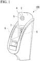
- FIG. 1 is a perspective view illustrating the outer appearance of a photographing apparatus according to the present embodiment.
- the photographing apparatus 100 is, for example, an apparatus incorporated into an entry/exit management system or the like for managing the entry and exit of people by facial authentication.
- the photographing apparatus 100 takes photographs of people who are entering or exiting a site.
- the photographing apparatus 100 is installed, for example, at a position at which photographs of the faces of entering or exiting people can be taken at an entrance/exit to a building, a property, or the like.
- the photographing apparatus 100 is configured so as to include a human sensor 3, a light-emitting device 4, a camera 5, slope LEDs (Light-Emitting Diodes) 6, and a display 7.
- the human sensor 3 detects a photographic subject in front of the photographing apparatus 100 by means of, for example, an infrared sensor or the like.
- the area in front of the photographing apparatus 100 is the direction in which the camera takes photographs.
- the camera 5 takes a photograph of the photographic subject in front of the photographing apparatus 100.
- the light-emitting device 4 is provided in the vicinity of the camera 5.
- the light-emitting device 4 is composed of a plurality of light-emitting bodies (for example, LEDs) that are installed in a ring along the circumferential direction around a lens of the camera 5.
- the light-emitting device 4 serves the function of drawing the photographic subject's attention towards the camera 5 and the function of a flash for the camera 5.
- the slope LEDs 6 are one or a plurality of light-emitting bodies installed on each of left and right slopes on the photographing apparatus 100.
- the slope LEDs 6 provide notification of the results of facial authentication.
- the display 7 is a display apparatus such as a liquid crystal display or an organic EL (Electro-Luminescence) display.
- the display 7 displays an image taken by the camera 5.
- FIG. 2 is a block diagram indicating the structure of the photographing apparatus.
- the photographing apparatus 100 is provided with at least a control apparatus 1, a facial authentication apparatus 2, the human sensor 3, the light-emitting device 4, the camera 5, the slope LEDs 6, and the display 7.
- the facial authentication apparatus 2 is a facial authentication engine that performs facial authentication by collating a facial photograph image of the photographic subject, taken by the camera 5 at a photograph-taking timing, with pre-stored facial photograph images of registrants.
- the registrants are, for example, people who are authorized to enter or exit a site.
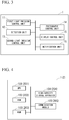
- FIG. 3 is a functional configuration diagram of the control apparatus.
- the control apparatus 1 controls the light emission of the light-emitting device 4 and the slope LEDs 6.
- the control apparatus 1 starts when a power source is connected, and executes a pre-stored photographing program.
- the control apparatus 1 is provided with at least a first light emission control unit 11, a detection unit 12, a second light emission control unit 13, a photography control unit 14, a display control unit 15, and a notification unit 16.
- the first light emission control unit 11 controls the light emission of the light-emitting device 4 in accordance with a first mode for drawing the photographic subject's attention towards the camera 5.
- the first mode involves blinking blue light.
- the detection unit 12 detects that a photograph-taking timing has arrived when the interocular distance of the photographic subject in an image generated by the camera 5 in accordance with the first mode becomes at least a prescribed distance.
- the second light emission control unit 13 controls the light emission of the light-emitting device 4, at the photograph-taking timing, in accordance with a second mode in which the light emission intensity is higher than in the first mode.
- the second mode for functioning as a flash for the camera 5, involves emitting white light at a brightness higher than that in the first mode.
- the photography control unit 14 acquires an image taken by the camera 5 at the photograph-taking timing for use in facial authentication, and outputs the acquired image to the facial authentication apparatus 2.
- the display control unit 15 controls a display on the display 7.
- the notification unit 16 controls the light emission of the slope LEDs 6 to provide notification of authentication results of the facial authentication in the facial authentication apparatus 2.
- FIG. 4 is a hardware configuration diagram of the control apparatus and the facial authentication apparatus.
- control apparatus 1 is a computer provided with hardware such as a CPU (Central Processing Unit) 101 (201), a ROM (Read-Only Memory) 102 (202), a RAM (Random Access Memory) 103 (203), a high-capacity storage apparatus 104 (204), and a communication module 105 (205).
- CPU Central Processing Unit
- ROM Read-Only Memory
- RAM Random Access Memory
- FIG. 5 is a diagram indicating the processing flow in the photographing apparatus.
- the first light emission control unit 11 in the photographing apparatus 100 determines whether or not the human sensor 3 has detected a photographic subject (step S101). If the human sensor 3 has not detected a photographic subject (step S101; No), then the first light emission control unit 11 repeats the process in step S101.
- the first light emission control unit 11 makes the light-emitting device 4 blink blue light (light emission is controlled under the first mode) (step S102).
- the photographic subject's attention can be drawn towards the camera 5 so that the facial orientation or the line of sight of the photographic subject is directed towards the camera 5.
- the photography control unit 14 instructs the camera 5 to take a photograph during light emission control in accordance with the first mode.
- the photography control unit 14 may instruct the camera 5 to take photographs multiple times.
- one or more sets of image data including images of the photographic subject in a state in which the photographic subject's attention is drawn towards the camera 5 can be generated. In other words, image data of the photographic subject in a state facing directly towards the camera 5 can be acquired.
- an image photographed and generated by the camera 5 in accordance with the first mode includes portions that can be recognized to be both irises of the photographic subject
- the detection unit 12 determines that the facial orientation of the photographic subject is directly towards the camera 5.
- the detection unit 12 computes the interocular distance of the photographic subject in the image including the portions that can be recognized to be both irises.
- the interocular distance is the distance between the left iris and the right iris.
- the detection unit 12 determines whether or not the interocular distance in the image has become at least a prescribed distance (step S103).
- the detection unit 12 can estimate the distance from the camera 5 to the photographic subject corresponding to the interocular distance in the image based, for example, on statistical information regarding interocular distances or the like. Therefore, the detection unit 12 can estimate the distance from the camera 5 to the photographic subject when the interocular distance has become at least the prescribed distance.
- the detection unit 12 determines that the distance from the photographic subject to the apparatus has become a distance suitable for taking a photograph when the interocular distance becomes at least the prescribed distance. Thus, if the interocular distance has become at least the prescribed distance (step S103; Yes), then the detection unit 12 detects that the photograph-taking timing has arrived.
- step S103 if the interocular distance has not become at least the prescribed distance (step S103; Yes), then the detection unit 12 repeats the process in step S103.
- the second light emission control unit 13 makes the light-emitting device 4 function as a flash for the camera 5, at the photograph-taking timing, by emitting white light having a brightness greater than in the first mode (light emission is controlled under the second mode in which the light emission intensity is higher than in the first mode) (step S104). As a result thereof, the photographic subject's face can be brightly lit to take a facial photograph suitable for facial authentication.
- the photography control unit 14 acquires a facial photograph image of the photographic subject taken by the camera 5 at the photograph-taking timing for use in facial authentication (step S 105). In other words, the photography control unit 14 instructs the camera 5 to take a photograph when light emission is controlled in accordance with the second mode at the photograph-taking timing.
- image data taken in a state in which the light emission intensity is high and in which the photographic subject is positioned within a prescribed distance range from the camera 5 and is facing directly towards the camera 5 can be acquired.
- the photography control unit 14 acquires the generated image data.
- the display control unit 15 displays, on the display 7, the facial photograph image that has been photographed and generated at the photograph-taking timing by the camera 5 (step S106).
- the photography control unit 14 outputs the acquired facial photograph image (image data including a facial image) to the facial authentication apparatus 2.
- the facial authentication apparatus 2 executes a facial authentication process for verifying that the photographic target is a registrant by collating the input image with pre-stored facial photograph images of registrants (step S107). In other words, the facial authentication apparatus 2 determines whether or not the photographic subject is the same person as a registrant by collating the image data including the facial image of the photographic subject with the pre-stored image data including the facial images of registrants.
- the facial authentication apparatus 2 outputs the authentication result to the control apparatus 1.
- the authentication result is "OK” if the photographic subject is a registrant and is "Failed” if the photographic subject is not a registrant.
- the notification unit 16 in the control apparatus 1 determines whether or not the authentication result input from the facial authentication apparatus 2 is "OK” or "Failed” (step S108).
- the notification unit 16 makes the slope LEDs 6 emit green light (step S109). As a result thereof, the photographic subject can be notified that the authentication result is "OK”. Thereafter, the process ends.
- the notification unit 16 makes the slope LEDs 6 emit red light (step S110). As a result thereof, the photographic subject can be notified that the authentication result is "Failed”. Thereafter, the process ends.
- the notification unit 16 may provide notification of the authentication results by outputting the authentication results in audio form from a speaker (not illustrated).
- the first light emission control unit 11 draws the photographic subject's attention towards the camera 5 by making the light-emitting device 4 blink blue light.
- the light emission mode is not limited thereto. Other light emission modes may be used as long as they are able to draw the photographic subject's attention towards the camera 5.
- the detection unit 12 detects that the photograph-taking timing has arrived when the interocular distance becomes at least a prescribed distance. However, in addition thereto, it can be determined that the photograph-taking timing has arrived when the photographic subject's line of sight is oriented directly towards the camera 5.
- the photographic subject's face can be brightly lit and photographed when the photographic subject's face is oriented directly towards the camera 5 and the distance from the photographic subject to the camera 5 has become a prescribed distance.
- an image that is suitable for facial authentication of the photographic subject who is advancing towards the camera 5 can be photographed.
- An image that is suitable for facial authentication is a facial photograph image of a prescribed size, in which the photographic subject's face is brightly captured, without shadows, and with the face or the line of sight oriented directly towards the camera 5.
- the light-emitting device 4 controls light emission in the first mode. For this reason, the photographic subject's attention can be directed towards the camera 5, and the orientation of the face or the orientation of the line of sight of the photographic subject can be directed towards the camera 5.
- the light-emitting device 4 which is provided near the camera 5, is illuminated.
- the photographic subject can more easily notice the camera 5 in comparison with an arrow, and the photographic subject's attention can immediately be drawn to the camera 5.
- the detection unit 12 detects that the photograph-taking timing has arrived when the interocular distance of the photographic subject becomes at least the prescribed distance based on the distance from the photographic subject to the apparatus. For this reason, a time at which the photographic subject's face is oriented directly towards the camera 5 and the distance from the photographic subject to the photographing apparatus 100 has become a distance suitable for photographing an image to be used for facial authentication can be identified as the photograph-taking timing. Furthermore, people other than those advancing towards the photographing apparatus 100, such as people crossing in front of the photographing apparatus 100, can be excluded from the facial authentication targets.
- the second light emission control unit 13 controls the light emission of the light-emitting device 4, at the photograph-taking timing, in accordance with a second mode in which the light emission intensity is higher than in the first mode. For this reason, the photographic subject's face can be brightly lit to take a facial photograph image suitable for facial authentication.
- the light-emitting device 4 for directing the photographic subject's attention towards the camera 5 also functions as a flash. For this reason, there is no need to install a separate light-emitting device for use as a flash, and the cost can be reduced. In other words, the drawing of the photographic subject's attention and the construction of an illuminated environment suitable for facial authentication can be realized with a single light-emitting device 4 being used in a sequence.
- the light-emitting device 4 is composed of a plurality of light-emitting bodies that are installed in a ring along the circumferential direction around a lens of the camera 5 was explained.
- the structure is not limited thereto.
- the light-emitting device 4 need only be installed in the vicinity of the camera 5, and for example, may be composed of a plurality of light-emitting bodies installed in a square around the lens of the camera. Additionally, the light-emitting device 4 may be composed of a single light-emitting body.
- FIG. 6 is a diagram indicating the minimum configuration of the photographing apparatus.
- the photographing apparatus 100 need only be provided with at least a camera 5, a light-emitting device 4, a human sensor 3, a first light emission control unit 11, a detection unit 12, and a second light emission control unit 13.
- the light-emitting device 4 is provided in the vicinity of the camera 5.
- the human sensor 3 detects a photographic subject.
- the first light emission control unit 11 controls the light emission of the light-emitting device 4 in accordance with a first mode when the photographic subject is detected.
- the detection unit 12 detects that a photograph-taking timing has arrived when an interocular distance of the photographic subject in an image generated by the camera 5 in accordance with the first mode becomes at least a prescribed distance.
- the second light emission control unit 13 controls the light emission of the light-emitting device 4, at the photograph-taking timing, in accordance with a second mode in which the light emission intensity is higher than in the first mode.
- the control apparatus 1 and the facial authentication apparatus 2 described above have computer systems contained therein. Furthermore, the steps in the above-described process are stored in a computer-readable recording medium in the form of a program, and the above-described process is performed by a computer reading out and executing this program.
- the computer-readable recording medium refers to a magnetic disc, a magneto-optic disc, a CD-ROM, a DVD-ROM, a semiconductor memory device, or the like.
- this computer program may be transmitted to a computer by means of a communication line and the computer that has received this transmission may execute said program.
- the above-mentioned program may be for realizing a portion of the aforementioned functions.
- the program may be in the form of a so-called difference file (difference program) that can realize the aforementioned functions by being combined with a program that is already recorded in a computer system.
- an image that is suitable for facial authentication of a photographic subject who is advancing towards a camera can be photographed.
Landscapes
- Engineering & Computer Science (AREA)
- Multimedia (AREA)
- Signal Processing (AREA)
- Physics & Mathematics (AREA)
- General Physics & Mathematics (AREA)
- Human Computer Interaction (AREA)
- General Health & Medical Sciences (AREA)
- Oral & Maxillofacial Surgery (AREA)
- Health & Medical Sciences (AREA)
- Theoretical Computer Science (AREA)
- Studio Devices (AREA)
- Image Input (AREA)
- Measurement Of The Respiration, Hearing Ability, Form, And Blood Characteristics Of Living Organisms (AREA)
- Stroboscope Apparatuses (AREA)
- Collating Specific Patterns (AREA)
- Indication In Cameras, And Counting Of Exposures (AREA)
- Image Analysis (AREA)
- Exposure Control For Cameras (AREA)
Abstract
Description
- The present disclosure relates to a photographing apparatus, a photographing method, and a storage medium having a program stored therein.
- A technology for improving authentication efficiency when performing facial authentication by generating light, sounds, or the like towards a walking photographic subject to make the photographic subject face a camera installation position is disclosed in
Patent Document 1. - [Patent Document 1]
Japanese Unexamined Patent Application, First Publication No. 2010-086350 - However, with the technology described in
Patent Document 1, there is a problem in that an image suitable for facial authentication sometimes cannot be photographed due to the distance from the camera to the photographic subject or the brightness of the surroundings. - Therefore, an example of an objective of the present invention is to provide a photographing apparatus, a photographing method, and a storage medium having a program stored therein, which solve the above-mentioned problem.
- According to a first aspect of the present invention, a photographing apparatus includes a camera; a light-emitting device provided in the vicinity of the camera; a human sensor that detects a photographic subject; first light emission control means for controlling light emission of the light-emitting device in accordance with a first mode when the photographic subject is detected; detection means for detecting that a photograph-taking timing has arrived when an interocular distance of the photographic subject in an image generated by the camera in accordance with the first mode becomes at least a prescribed distance; and second light emission control means for controlling light emission of the light-emitting device, at the photograph-taking timing, in accordance with a second mode in which a light emission intensity is higher than in the first mode.
- According to a second aspect of the present invention, a photographing method includes controlling light emission of a light-emitting device provided in the vicinity of a camera in accordance with a first mode when a photographic subject is detected by a human sensor; detecting that a photograph-taking timing has arrived when an interocular distance of the photographic subject in an image generated by the camera in accordance with the first mode becomes at least a prescribed distance; and controlling light emission of the light-emitting device, at the photograph-taking timing, in accordance with a second mode in which a light emission intensity is higher than in the first mode.
- According to a third aspect of the present invention, a program stored in a storage medium causes a computer in a photographing apparatus to execute processes. The processes includes controlling light emission of a light-emitting device provided in the vicinity of a camera in accordance with a first mode when a photographic subject is detected by a human sensor; detecting that a photograph-taking timing has arrived when an interocular distance of the photographic subject in an image generated by the camera in accordance with the first mode becomes at least a prescribed distance; and controlling light emission of the light-emitting device, at the photograph-taking timing, in accordance with a second mode in which a light emission intensity is higher than in the first mode.
- According to the present disclosure, an image that is suitable for facial authentication of a photographic subject who is advancing towards a camera can be photographed.
-
-
FIG. 1 is a perspective view illustrating the outer appearance of a photographing apparatus according to the present embodiment. -
FIG. 2 is a block diagram indicating the structure of the photographing apparatus according to the present embodiment. -
FIG. 3 is a functional configuration diagram of the photographing apparatus according to the present embodiment. -
FIG. 4 is a hardware configuration diagram of a control apparatus and a facial authentication apparatus according to the present embodiment. -
FIG. 5 is a diagram indicating the processing flow in the photographing apparatus according to the present embodiment. -
FIG. 6 is a diagram indicating the minimum configuration of the photographing apparatus according to the present embodiment. - Hereinafter, a photographing apparatus according to an embodiment of the present disclosure will be explained with reference to the drawings.
-
FIG. 1 is a perspective view illustrating the outer appearance of a photographing apparatus according to the present embodiment. - The photographing
apparatus 100 is, for example, an apparatus incorporated into an entry/exit management system or the like for managing the entry and exit of people by facial authentication. The photographingapparatus 100 takes photographs of people who are entering or exiting a site. The photographingapparatus 100 is installed, for example, at a position at which photographs of the faces of entering or exiting people can be taken at an entrance/exit to a building, a property, or the like. - As illustrated in
FIG. 1 , the photographingapparatus 100 is configured so as to include ahuman sensor 3, a light-emitting device 4, acamera 5, slope LEDs (Light-Emitting Diodes) 6, and adisplay 7. - The
human sensor 3 detects a photographic subject in front of the photographingapparatus 100 by means of, for example, an infrared sensor or the like. The area in front of the photographingapparatus 100 is the direction in which the camera takes photographs. - The
camera 5 takes a photograph of the photographic subject in front of the photographingapparatus 100. - The light-
emitting device 4 is provided in the vicinity of thecamera 5. For example, the light-emittingdevice 4 is composed of a plurality of light-emitting bodies (for example, LEDs) that are installed in a ring along the circumferential direction around a lens of thecamera 5. The light-emitting device 4 serves the function of drawing the photographic subject's attention towards thecamera 5 and the function of a flash for thecamera 5. - The
slope LEDs 6 are one or a plurality of light-emitting bodies installed on each of left and right slopes on the photographingapparatus 100. Theslope LEDs 6 provide notification of the results of facial authentication. - The
display 7 is a display apparatus such as a liquid crystal display or an organic EL (Electro-Luminescence) display. Thedisplay 7 displays an image taken by thecamera 5. -
FIG. 2 is a block diagram indicating the structure of the photographing apparatus. - The photographing
apparatus 100 is provided with at least acontrol apparatus 1, afacial authentication apparatus 2, thehuman sensor 3, the light-emitting device 4, thecamera 5, theslope LEDs 6, and thedisplay 7. - The
facial authentication apparatus 2 is a facial authentication engine that performs facial authentication by collating a facial photograph image of the photographic subject, taken by thecamera 5 at a photograph-taking timing, with pre-stored facial photograph images of registrants. The registrants are, for example, people who are authorized to enter or exit a site. -
FIG. 3 is a functional configuration diagram of the control apparatus. - The
control apparatus 1 controls the light emission of the light-emitting device 4 and theslope LEDs 6. Thecontrol apparatus 1 starts when a power source is connected, and executes a pre-stored photographing program. As a result thereof, thecontrol apparatus 1 is provided with at least a first lightemission control unit 11, adetection unit 12, a second lightemission control unit 13, aphotography control unit 14, adisplay control unit 15, and anotification unit 16. - When a photographic subject is detected, the first light
emission control unit 11 controls the light emission of the light-emitting device 4 in accordance with a first mode for drawing the photographic subject's attention towards thecamera 5. For example, the first mode involves blinking blue light. - The
detection unit 12 detects that a photograph-taking timing has arrived when the interocular distance of the photographic subject in an image generated by thecamera 5 in accordance with the first mode becomes at least a prescribed distance. - The second light
emission control unit 13 controls the light emission of the light-emitting device 4, at the photograph-taking timing, in accordance with a second mode in which the light emission intensity is higher than in the first mode. For example, the second mode, for functioning as a flash for thecamera 5, involves emitting white light at a brightness higher than that in the first mode. - The
photography control unit 14 acquires an image taken by thecamera 5 at the photograph-taking timing for use in facial authentication, and outputs the acquired image to thefacial authentication apparatus 2. - The
display control unit 15 controls a display on thedisplay 7. - The
notification unit 16 controls the light emission of theslope LEDs 6 to provide notification of authentication results of the facial authentication in thefacial authentication apparatus 2. -
FIG. 4 is a hardware configuration diagram of the control apparatus and the facial authentication apparatus. - As indicated by the drawing, the control apparatus 1 (facial authentication apparatus 2) is a computer provided with hardware such as a CPU (Central Processing Unit) 101 (201), a ROM (Read-Only Memory) 102 (202), a RAM (Random Access Memory) 103 (203), a high-capacity storage apparatus 104 (204), and a communication module 105 (205).
-
FIG. 5 is a diagram indicating the processing flow in the photographing apparatus. - Next, the processing flow in the photographing apparatus will be explained in order.
- First, the first light
emission control unit 11 in the photographingapparatus 100 determines whether or not thehuman sensor 3 has detected a photographic subject (step S101). If thehuman sensor 3 has not detected a photographic subject (step S101; No), then the first lightemission control unit 11 repeats the process in step S101. - On the other hand, if the
human sensor 3 has detected a photographic subject (step S101; Yes), then the first lightemission control unit 11 makes the light-emitting device 4 blink blue light (light emission is controlled under the first mode) (step S102). As a result thereof, the photographic subject's attention can be drawn towards thecamera 5 so that the facial orientation or the line of sight of the photographic subject is directed towards thecamera 5. Thephotography control unit 14 instructs thecamera 5 to take a photograph during light emission control in accordance with the first mode. Thephotography control unit 14 may instruct thecamera 5 to take photographs multiple times. As a result thereof, one or more sets of image data including images of the photographic subject in a state in which the photographic subject's attention is drawn towards thecamera 5 can be generated. In other words, image data of the photographic subject in a state facing directly towards thecamera 5 can be acquired. - Next, if an image photographed and generated by the
camera 5 in accordance with the first mode includes portions that can be recognized to be both irises of the photographic subject, then thedetection unit 12 determines that the facial orientation of the photographic subject is directly towards thecamera 5. Thedetection unit 12 computes the interocular distance of the photographic subject in the image including the portions that can be recognized to be both irises. The interocular distance is the distance between the left iris and the right iris. Thedetection unit 12 determines whether or not the interocular distance in the image has become at least a prescribed distance (step S103). - If the interocular distance in the image photographed by the
camera 5 has become at least the prescribed distance, then the following assumptions can be made: the photographic subject is facing directly towards thecamera 5; the photographic subject is advancing towards thecamera 5; and the distance from thecamera 5 to the photographic subject is a distance (for example, 60 cm to 120 cm, etc.) suitable for photographing an image (facial photograph) to be used for performing facial authentication. Thedetection unit 12 can estimate the distance from thecamera 5 to the photographic subject corresponding to the interocular distance in the image based, for example, on statistical information regarding interocular distances or the like. Therefore, thedetection unit 12 can estimate the distance from thecamera 5 to the photographic subject when the interocular distance has become at least the prescribed distance. Thedetection unit 12 determines that the distance from the photographic subject to the apparatus has become a distance suitable for taking a photograph when the interocular distance becomes at least the prescribed distance. Thus, if the interocular distance has become at least the prescribed distance (step S103; Yes), then thedetection unit 12 detects that the photograph-taking timing has arrived. - On the other hand, if the interocular distance has not become at least the prescribed distance (step S103; Yes), then the
detection unit 12 repeats the process in step S103. - The second light
emission control unit 13 makes the light-emittingdevice 4 function as a flash for thecamera 5, at the photograph-taking timing, by emitting white light having a brightness greater than in the first mode (light emission is controlled under the second mode in which the light emission intensity is higher than in the first mode) (step S104). As a result thereof, the photographic subject's face can be brightly lit to take a facial photograph suitable for facial authentication. Thephotography control unit 14 acquires a facial photograph image of the photographic subject taken by thecamera 5 at the photograph-taking timing for use in facial authentication (step S 105). In other words, thephotography control unit 14 instructs thecamera 5 to take a photograph when light emission is controlled in accordance with the second mode at the photograph-taking timing. As a result thereof, image data taken in a state in which the light emission intensity is high and in which the photographic subject is positioned within a prescribed distance range from thecamera 5 and is facing directly towards thecamera 5 can be acquired. Thephotography control unit 14 acquires the generated image data. Thedisplay control unit 15 displays, on thedisplay 7, the facial photograph image that has been photographed and generated at the photograph-taking timing by the camera 5 (step S106). - The
photography control unit 14 outputs the acquired facial photograph image (image data including a facial image) to thefacial authentication apparatus 2. Thefacial authentication apparatus 2 executes a facial authentication process for verifying that the photographic target is a registrant by collating the input image with pre-stored facial photograph images of registrants (step S107). In other words, thefacial authentication apparatus 2 determines whether or not the photographic subject is the same person as a registrant by collating the image data including the facial image of the photographic subject with the pre-stored image data including the facial images of registrants. - The
facial authentication apparatus 2 outputs the authentication result to thecontrol apparatus 1. The authentication result is "OK" if the photographic subject is a registrant and is "Failed" if the photographic subject is not a registrant. Thenotification unit 16 in thecontrol apparatus 1 determines whether or not the authentication result input from thefacial authentication apparatus 2 is "OK" or "Failed" (step S108). - If the authentication result is "OK", then the
notification unit 16 makes theslope LEDs 6 emit green light (step S109). As a result thereof, the photographic subject can be notified that the authentication result is "OK". Thereafter, the process ends. On the other hand, if the authentication result is "Failed", then thenotification unit 16 makes theslope LEDs 6 emit red light (step S110). As a result thereof, the photographic subject can be notified that the authentication result is "Failed". Thereafter, the process ends. - In the above-described process, the
notification unit 16 may provide notification of the authentication results by outputting the authentication results in audio form from a speaker (not illustrated). - Additionally, in the above-described process, the first light
emission control unit 11 draws the photographic subject's attention towards thecamera 5 by making the light-emittingdevice 4 blink blue light. However, the light emission mode is not limited thereto. Other light emission modes may be used as long as they are able to draw the photographic subject's attention towards thecamera 5. - Additionally, in the above-described process, the
detection unit 12 detects that the photograph-taking timing has arrived when the interocular distance becomes at least a prescribed distance. However, in addition thereto, it can be determined that the photograph-taking timing has arrived when the photographic subject's line of sight is oriented directly towards thecamera 5. - According to the above-described process, the photographic subject's face can be brightly lit and photographed when the photographic subject's face is oriented directly towards the
camera 5 and the distance from the photographic subject to thecamera 5 has become a prescribed distance. Thus, an image that is suitable for facial authentication of the photographic subject who is advancing towards thecamera 5 can be photographed. An image that is suitable for facial authentication is a facial photograph image of a prescribed size, in which the photographic subject's face is brightly captured, without shadows, and with the face or the line of sight oriented directly towards thecamera 5. - Additionally, according to the above-described process, when the first light
emission control unit 11 has detected a photographic subject, the light-emittingdevice 4 controls light emission in the first mode. For this reason, the photographic subject's attention can be directed towards thecamera 5, and the orientation of the face or the orientation of the line of sight of the photographic subject can be directed towards thecamera 5. - Although a method, for example, in which an arrow pointing towards the
camera 5 is displayed on thedisplay 7 or the like to draw the photographic subject's attention towards thecamera 5 might be contemplated, in this case, the photographic subject often does not notice or is late to notice the arrow. Additionally, in this case, the photographic subject first looks at the arrow and then looks at thecamera 5. Thus, some time passes before the photographic subject's attention is turned towards thecamera 5, and this time causes a delay in facial authentication. - In contrast therewith, with the above-described photographing
apparatus 100, the light-emittingdevice 4, which is provided near thecamera 5, is illuminated. For this reason, the photographic subject can more easily notice thecamera 5 in comparison with an arrow, and the photographic subject's attention can immediately be drawn to thecamera 5. - Additionally, according to the above-described process, the
detection unit 12 detects that the photograph-taking timing has arrived when the interocular distance of the photographic subject becomes at least the prescribed distance based on the distance from the photographic subject to the apparatus. For this reason, a time at which the photographic subject's face is oriented directly towards thecamera 5 and the distance from the photographic subject to the photographingapparatus 100 has become a distance suitable for photographing an image to be used for facial authentication can be identified as the photograph-taking timing. Furthermore, people other than those advancing towards the photographingapparatus 100, such as people crossing in front of the photographingapparatus 100, can be excluded from the facial authentication targets. - Additionally, according to the above-described process, the second light
emission control unit 13 controls the light emission of the light-emittingdevice 4, at the photograph-taking timing, in accordance with a second mode in which the light emission intensity is higher than in the first mode. For this reason, the photographic subject's face can be brightly lit to take a facial photograph image suitable for facial authentication. - Additionally, according to the above-described process, the light-emitting
device 4 for directing the photographic subject's attention towards thecamera 5 also functions as a flash. For this reason, there is no need to install a separate light-emitting device for use as a flash, and the cost can be reduced. In other words, the drawing of the photographic subject's attention and the construction of an illuminated environment suitable for facial authentication can be realized with a single light-emittingdevice 4 being used in a sequence. - While an embodiment of the present disclosure has been described above, this disclosure is not limited to the above-described embodiment, and various modifications may be made within a scope not departing from the spirit of the present disclosure.
- For example, in the above-described embodiment, a case in which the light-emitting
device 4 is composed of a plurality of light-emitting bodies that are installed in a ring along the circumferential direction around a lens of thecamera 5 was explained. However, the structure is not limited thereto. The light-emittingdevice 4 need only be installed in the vicinity of thecamera 5, and for example, may be composed of a plurality of light-emitting bodies installed in a square around the lens of the camera. Additionally, the light-emittingdevice 4 may be composed of a single light-emitting body. -
FIG. 6 is a diagram indicating the minimum configuration of the photographing apparatus. - The photographing
apparatus 100 need only be provided with at least acamera 5, a light-emittingdevice 4, ahuman sensor 3, a first lightemission control unit 11, adetection unit 12, and a second lightemission control unit 13. - The light-emitting
device 4 is provided in the vicinity of thecamera 5. - The
human sensor 3 detects a photographic subject. - The first light
emission control unit 11 controls the light emission of the light-emittingdevice 4 in accordance with a first mode when the photographic subject is detected. - The
detection unit 12 detects that a photograph-taking timing has arrived when an interocular distance of the photographic subject in an image generated by thecamera 5 in accordance with the first mode becomes at least a prescribed distance. - The second light
emission control unit 13 controls the light emission of the light-emittingdevice 4, at the photograph-taking timing, in accordance with a second mode in which the light emission intensity is higher than in the first mode. - The
control apparatus 1 and thefacial authentication apparatus 2 described above have computer systems contained therein. Furthermore, the steps in the above-described process are stored in a computer-readable recording medium in the form of a program, and the above-described process is performed by a computer reading out and executing this program. In this case, the computer-readable recording medium refers to a magnetic disc, a magneto-optic disc, a CD-ROM, a DVD-ROM, a semiconductor memory device, or the like. Additionally, this computer program may be transmitted to a computer by means of a communication line and the computer that has received this transmission may execute said program. - Additionally, the above-mentioned program may be for realizing a portion of the aforementioned functions. Furthermore, the program may be in the form of a so-called difference file (difference program) that can realize the aforementioned functions by being combined with a program that is already recorded in a computer system.
- The present application claims the benefit of priority based on
Japanese Patent Application No. 2019-041795, filed March 7, 2019 - According to the present disclosure, an image that is suitable for facial authentication of a photographic subject who is advancing towards a camera can be photographed.
-
- 100
- Photographing apparatus
- 1
- Control apparatus
- 11
- First light emission control unit
- 12
- Detection unit
- 13
- Second light emission control unit
- 14
- Photography control unit
- 15
- Display control unit
- 16
- Notification unit
- 2
- Facial authentication apparatus
- 3
- Human sensor
- 4
- Light-emitting device
- 5
- Camera
- 6
- Slope LED
- 7
- Display
Claims (8)
- A photographing apparatus comprising:a camera;a light-emitting device provided in the vicinity of the camera;a human sensor that detects a photographic subject;first light emission control means for controlling light emission of the light-emitting device in accordance with a first mode when the photographic subject is detected;detection means for detecting that a photograph-taking timing has arrived when an interocular distance of the photographic subject in an image generated by the camera in accordance with the first mode becomes at least a prescribed distance; andsecond light emission control means for controlling light emission of the light-emitting device, at the photograph-taking timing, in accordance with a second mode in which a light emission intensity is higher than in the first mode.
- The photographing apparatus according to claim 1, further comprising
photography control means for acquiring an image photographed and generated by the camera at the photograph-taking timing for use in facial authentication. - The photographing apparatus according to claim 1 or claim 2, wherein
the second light emission control means controls light emission of the light-emitting device in accordance with the second mode for functioning as a flash for the camera. - The photographing apparatus according to any one of claims 1 to 3, wherein
the first light emission control means controls light emission of the light-emitting device in accordance with the first mode for drawing the photographic subject's attention towards the camera. - The photographing apparatus according to any one of claims 1 to 4, wherein
the light-emitting device includes a plurality of light-emitting bodies installed in a ring around a lens of the camera. - The photographing apparatus according to any one of claims 1 to 5, wherein
the detection means determines that a distance from the photographic subject to the photographing apparatus has become suitable for taking a photograph when the interocular distance of the photographic subject in the image becomes at least the prescribed distance. - A photographing method comprising:controlling light emission of a light-emitting device provided in the vicinity of a camera in accordance with a first mode when a photographic subject is detected by a human sensor;detecting that a photograph-taking timing has arrived when an interocular distance of the photographic subject in an image generated by the camera in accordance with the first mode becomes at least a prescribed distance; andcontrolling light emission of the light-emitting device, at the photograph-taking timing, in accordance with a second mode in which a light emission intensity is higher than in the first mode.
- A storage medium storing a program that causes a computer in a photographing apparatus to execute processes, the processes comprising:controlling light emission of a light-emitting device provided in the vicinity of a camera in accordance with a first mode when a photographic subject is detected by a human sensor;detecting that a photograph-taking timing has arrived when an interocular distance of the photographic subject in an image generated by the camera in accordance with the first mode becomes at least a prescribed distance; andcontrolling light emission of the light-emitting device, at the photograph-taking timing, in accordance with a second mode in which a light emission intensity is higher than in the first mode.
Applications Claiming Priority (2)
| Application Number | Priority Date | Filing Date | Title |
|---|---|---|---|
| JP2019041795 | 2019-03-07 | ||
| PCT/JP2020/009582 WO2020179898A1 (en) | 2019-03-07 | 2020-03-06 | Photographing apparatus, photographing method, and storage medium having program stored therein |
Publications (2)
| Publication Number | Publication Date |
|---|---|
| EP3937479A1 true EP3937479A1 (en) | 2022-01-12 |
| EP3937479A4 EP3937479A4 (en) | 2022-05-18 |
Family
ID=72338114
Family Applications (1)
| Application Number | Title | Priority Date | Filing Date |
|---|---|---|---|
| EP20766747.8A Withdrawn EP3937479A4 (en) | 2019-03-07 | 2020-03-06 | Photographing apparatus, photographing method, and storage medium having program stored therein |
Country Status (5)
| Country | Link |
|---|---|
| US (2) | US11930265B2 (en) |
| EP (1) | EP3937479A4 (en) |
| JP (2) | JP7151867B2 (en) |
| CN (1) | CN113545029A (en) |
| WO (1) | WO2020179898A1 (en) |
Families Citing this family (2)
| Publication number | Priority date | Publication date | Assignee | Title |
|---|---|---|---|---|
| US11930265B2 (en) | 2019-03-07 | 2024-03-12 | Nec Corporation | Photographing apparatus, photographing method, and storage medium having program stored therein |
| TW202444867A (en) | 2022-11-22 | 2024-11-16 | 日商Agc股份有限公司 | Water repellent composition, manufacturing method, processing method and article of non-fluorinated polymer |
Family Cites Families (23)
| Publication number | Priority date | Publication date | Assignee | Title |
|---|---|---|---|---|
| JP2001174884A (en) | 1999-12-16 | 2001-06-29 | Ricoh Co Ltd | Strobe photography device |
| JP4870887B2 (en) | 2001-09-28 | 2012-02-08 | 株式会社リコー | Imaging apparatus, strobe control method, and program for computer to execute the method |
| JP2003222947A (en) | 2002-01-30 | 2003-08-08 | Olympus Optical Co Ltd | Camera |
| JP2003177459A (en) | 2001-12-11 | 2003-06-27 | Konica Corp | Automatic picture taking device |
| JP4708879B2 (en) * | 2005-06-24 | 2011-06-22 | グローリー株式会社 | Face authentication apparatus and face authentication method |
| JP2007025154A (en) | 2005-07-14 | 2007-02-01 | Fujinon Corp | Lens barrel |
| JP2007047544A (en) | 2005-08-11 | 2007-02-22 | Fujifilm Holdings Corp | Strobe apparatus |
| JP5004544B2 (en) * | 2006-09-29 | 2012-08-22 | 富士フイルム株式会社 | Imaging apparatus and exposure control method |
| JP2008139973A (en) | 2006-11-30 | 2008-06-19 | Funai Electric Co Ltd | Face image authentication system and imaging device |
| JP2008199522A (en) | 2007-02-15 | 2008-08-28 | Fujifilm Corp | Imaging apparatus and imaging method |
| TWI351215B (en) | 2007-10-05 | 2011-10-21 | Hon Hai Prec Ind Co Ltd | Photographing device |
| JP2010086350A (en) | 2008-09-30 | 2010-04-15 | Toshiba Corp | Authentication device |
| JP2013242504A (en) | 2012-05-23 | 2013-12-05 | Sony Corp | Electronic mirror device, electronic mirror display method, and electronic mirror program |
| KR101569268B1 (en) * | 2014-01-02 | 2015-11-13 | 아이리텍 잉크 | Acquisition System and Method of Iris image for iris recognition by using facial component distance |
| JP2016050972A (en) | 2014-08-29 | 2016-04-11 | ソニー株式会社 | Control device, control method, and program |
| JP6233375B2 (en) | 2015-09-18 | 2017-11-22 | 株式会社ニコン | Electronics |
| JPWO2017073045A1 (en) | 2015-10-28 | 2018-08-02 | 京セラ株式会社 | IMAGING DEVICE, IMAGING SYSTEM, SUBJECT MONITORING SYSTEM, AND IMAGING DEVICE CONTROL METHOD |
| JP2018005135A (en) | 2016-07-08 | 2018-01-11 | キヤノン株式会社 | Lens barrel and optical instrument |
| KR102547054B1 (en) * | 2016-07-29 | 2023-06-23 | 삼성전자주식회사 | Electronic device and method for controlling activation of camera module |
| JP6887346B2 (en) | 2017-08-29 | 2021-06-16 | 株式会社日立製作所 | High frequency coil unit and magnetic resonance imaging device |
| US10200623B1 (en) * | 2017-10-17 | 2019-02-05 | Qualcomm Incorporated | Image capture setting determination in flash photography operations |
| CN109104554A (en) | 2018-08-27 | 2018-12-28 | 惠州Tcl移动通信有限公司 | A kind of ring flash of light control camera assembly, mobile terminal and its assembly method |
| US11930265B2 (en) | 2019-03-07 | 2024-03-12 | Nec Corporation | Photographing apparatus, photographing method, and storage medium having program stored therein |
-
2020
- 2020-03-06 US US17/435,495 patent/US11930265B2/en active Active
- 2020-03-06 CN CN202080019142.6A patent/CN113545029A/en active Pending
- 2020-03-06 EP EP20766747.8A patent/EP3937479A4/en not_active Withdrawn
- 2020-03-06 JP JP2021503659A patent/JP7151867B2/en active Active
- 2020-03-06 WO PCT/JP2020/009582 patent/WO2020179898A1/en not_active Ceased
-
2022
- 2022-09-29 JP JP2022156129A patent/JP7563437B2/en active Active
-
2024
- 2024-02-06 US US18/433,640 patent/US20240179392A1/en active Pending
Also Published As
| Publication number | Publication date |
|---|---|
| WO2020179898A1 (en) | 2020-09-10 |
| US20220141380A1 (en) | 2022-05-05 |
| JPWO2020179898A1 (en) | 2021-12-02 |
| EP3937479A4 (en) | 2022-05-18 |
| US20240179392A1 (en) | 2024-05-30 |
| JP2022186729A (en) | 2022-12-15 |
| JP7151867B2 (en) | 2022-10-12 |
| US11930265B2 (en) | 2024-03-12 |
| JP7563437B2 (en) | 2024-10-08 |
| CN113545029A (en) | 2021-10-22 |
Similar Documents
| Publication | Publication Date | Title |
|---|---|---|
| US20240179392A1 (en) | Photographing apparatus, photographing method, and storage medium having program stored therein | |
| JP2004261515A (en) | Iris imaging device | |
| US20230135416A1 (en) | Facial authentication apparatus and control method for facial authentication apparatus | |
| KR101655839B1 (en) | Parking management system using fisheye lens camera and method thereof | |
| US20130301886A1 (en) | Authentication card, authentication system, guidance method, and program | |
| JPWO2020075308A1 (en) | Information processing device | |
| EP3893488B1 (en) | Solid-state imaging device, solid-state imaging method, and electronic apparatus | |
| US10124799B2 (en) | Vehicle safety control apparatus and method using cameras | |
| KR101297759B1 (en) | Ir led controlling apparatus for cctv and method thereof | |
| JP6447425B2 (en) | Violation suppression device and violation suppression system provided with the same | |
| CN103929542A (en) | Mobile terminals and photographing method and device thereof | |
| CN110930622A (en) | Power supply and distribution area electronic alarm device | |
| CN107415806A (en) | Intelligent warning lamp based on image recognition | |
| JP2022144030A (en) | camera system and lighting system | |
| JP2023007006A (en) | Face authentication system and face authentication method | |
| JP5285190B1 (en) | Street light and photography system | |
| JP2000132681A (en) | Device for obtaining iris data | |
| KR100609431B1 (en) | Vehicle access management system with electric bulletin board and lighting | |
| JP5104369B2 (en) | Face recognition device and face recognition method | |
| JP2016192113A (en) | Vehicle collating system | |
| JP2019012958A (en) | Photographing control device, photographing apparatus for vehicle, photographing control method and program | |
| JP2014179053A (en) | Street light and photographing system | |
| US20210255526A1 (en) | Imaging apparatus, electronic device, and notification method | |
| HK40014830A (en) | Face recognition method and device, electronic equipment and storage medium | |
| WO2024214289A1 (en) | Display device, authentication system, authentication method, and recording medium |
Legal Events
| Date | Code | Title | Description |
|---|---|---|---|
| STAA | Information on the status of an ep patent application or granted ep patent |
Free format text: STATUS: THE INTERNATIONAL PUBLICATION HAS BEEN MADE |
|
| PUAI | Public reference made under article 153(3) epc to a published international application that has entered the european phase |
Free format text: ORIGINAL CODE: 0009012 |
|
| STAA | Information on the status of an ep patent application or granted ep patent |
Free format text: STATUS: REQUEST FOR EXAMINATION WAS MADE |
|
| 17P | Request for examination filed |
Effective date: 20210901 |
|
| AK | Designated contracting states |
Kind code of ref document: A1 Designated state(s): AL AT BE BG CH CY CZ DE DK EE ES FI FR GB GR HR HU IE IS IT LI LT LU LV MC MK MT NL NO PL PT RO RS SE SI SK SM TR |
|
| A4 | Supplementary search report drawn up and despatched |
Effective date: 20220414 |
|
| RIC1 | Information provided on ipc code assigned before grant |
Ipc: H04N 5/235 20060101ALI20220408BHEP Ipc: H04N 5/225 20060101ALI20220408BHEP Ipc: G06T 7/00 20170101ALI20220408BHEP Ipc: G06T 1/00 20060101ALI20220408BHEP Ipc: G03B 15/05 20210101ALI20220408BHEP Ipc: G03B 15/03 20210101ALI20220408BHEP Ipc: G03B 15/00 20210101ALI20220408BHEP Ipc: H04N 5/232 20060101AFI20220408BHEP |
|
| DAV | Request for validation of the european patent (deleted) | ||
| DAX | Request for extension of the european patent (deleted) | ||
| STAA | Information on the status of an ep patent application or granted ep patent |
Free format text: STATUS: THE APPLICATION HAS BEEN WITHDRAWN |
|
| 18W | Application withdrawn |
Effective date: 20230213 |