EP3936765B1 - Verbrennungssystem mit einem denitrierungskatalysator - Google Patents
Verbrennungssystem mit einem denitrierungskatalysator Download PDFInfo
- Publication number
- EP3936765B1 EP3936765B1 EP19917753.6A EP19917753A EP3936765B1 EP 3936765 B1 EP3936765 B1 EP 3936765B1 EP 19917753 A EP19917753 A EP 19917753A EP 3936765 B1 EP3936765 B1 EP 3936765B1
- Authority
- EP
- European Patent Office
- Prior art keywords
- denitration
- catalyst
- exhaust gas
- denitration catalyst
- combustion system
- Prior art date
- Legal status (The legal status is an assumption and is not a legal conclusion. Google has not performed a legal analysis and makes no representation as to the accuracy of the status listed.)
- Active
Links
Images









Classifications
-
- F—MECHANICAL ENGINEERING; LIGHTING; HEATING; WEAPONS; BLASTING
- F01—MACHINES OR ENGINES IN GENERAL; ENGINE PLANTS IN GENERAL; STEAM ENGINES
- F01N—GAS-FLOW SILENCERS OR EXHAUST APPARATUS FOR MACHINES OR ENGINES IN GENERAL; GAS-FLOW SILENCERS OR EXHAUST APPARATUS FOR INTERNAL-COMBUSTION ENGINES
- F01N3/00—Exhaust or silencing apparatus having means for purifying, rendering innocuous, or otherwise treating exhaust
- F01N3/08—Exhaust or silencing apparatus having means for purifying, rendering innocuous, or otherwise treating exhaust for rendering innocuous
- F01N3/10—Exhaust or silencing apparatus having means for purifying, rendering innocuous, or otherwise treating exhaust for rendering innocuous by thermal or catalytic conversion of noxious components of exhaust
- F01N3/18—Exhaust or silencing apparatus having means for purifying, rendering innocuous, or otherwise treating exhaust for rendering innocuous by thermal or catalytic conversion of noxious components of exhaust characterised by methods of operation; Control
- F01N3/20—Exhaust or silencing apparatus having means for purifying, rendering innocuous, or otherwise treating exhaust for rendering innocuous by thermal or catalytic conversion of noxious components of exhaust characterised by methods of operation; Control specially adapted for catalytic conversion
- F01N3/206—Adding periodically or continuously substances to exhaust gases for promoting purification, e.g. catalytic material in liquid form, NOx reducing agents
- F01N3/2066—Selective catalytic reduction [SCR]
- F01N3/2073—Means for generating a reducing substance from the exhaust gases
-
- F—MECHANICAL ENGINEERING; LIGHTING; HEATING; WEAPONS; BLASTING
- F23—COMBUSTION APPARATUS; COMBUSTION PROCESSES
- F23J—REMOVAL OR TREATMENT OF COMBUSTION PRODUCTS OR COMBUSTION RESIDUES; FLUES
- F23J15/00—Arrangements of devices for treating smoke or fumes
- F23J15/02—Arrangements of devices for treating smoke or fumes of purifiers, e.g. for removing noxious material
- F23J15/022—Arrangements of devices for treating smoke or fumes of purifiers, e.g. for removing noxious material for removing solid particulate material from the gasflow
- F23J15/025—Arrangements of devices for treating smoke or fumes of purifiers, e.g. for removing noxious material for removing solid particulate material from the gasflow using filters
-
- B—PERFORMING OPERATIONS; TRANSPORTING
- B01—PHYSICAL OR CHEMICAL PROCESSES OR APPARATUS IN GENERAL
- B01D—SEPARATION
- B01D53/00—Separation of gases or vapours; Recovering vapours of volatile solvents from gases; Chemical or biological purification of waste gases, e.g. engine exhaust gases, smoke, fumes, flue gases, aerosols
- B01D53/34—Chemical or biological purification of waste gases
- B01D53/74—General processes for purification of waste gases; Apparatus or devices specially adapted therefor
- B01D53/86—Catalytic processes
- B01D53/8621—Removing nitrogen compounds
- B01D53/8625—Nitrogen oxides
- B01D53/8628—Processes characterised by a specific catalyst
-
- B—PERFORMING OPERATIONS; TRANSPORTING
- B01—PHYSICAL OR CHEMICAL PROCESSES OR APPARATUS IN GENERAL
- B01J—CHEMICAL OR PHYSICAL PROCESSES, e.g. CATALYSIS OR COLLOID CHEMISTRY; THEIR RELEVANT APPARATUS
- B01J23/00—Catalysts comprising metals or metal oxides or hydroxides, not provided for in group B01J21/00
- B01J23/16—Catalysts comprising metals or metal oxides or hydroxides, not provided for in group B01J21/00 of arsenic, antimony, bismuth, vanadium, niobium, tantalum, polonium, chromium, molybdenum, tungsten, manganese, technetium or rhenium
- B01J23/20—Vanadium, niobium or tantalum
- B01J23/22—Vanadium
-
- B—PERFORMING OPERATIONS; TRANSPORTING
- B01—PHYSICAL OR CHEMICAL PROCESSES OR APPARATUS IN GENERAL
- B01J—CHEMICAL OR PHYSICAL PROCESSES, e.g. CATALYSIS OR COLLOID CHEMISTRY; THEIR RELEVANT APPARATUS
- B01J35/00—Catalysts, in general, characterised by their form or physical properties
- B01J35/70—Catalysts, in general, characterised by their form or physical properties characterised by their crystalline properties, e.g. semi-crystalline
-
- B—PERFORMING OPERATIONS; TRANSPORTING
- B01—PHYSICAL OR CHEMICAL PROCESSES OR APPARATUS IN GENERAL
- B01J—CHEMICAL OR PHYSICAL PROCESSES, e.g. CATALYSIS OR COLLOID CHEMISTRY; THEIR RELEVANT APPARATUS
- B01J37/00—Processes, in general, for preparing catalysts; Processes, in general, for activation of catalysts
- B01J37/08—Heat treatment
-
- F—MECHANICAL ENGINEERING; LIGHTING; HEATING; WEAPONS; BLASTING
- F01—MACHINES OR ENGINES IN GENERAL; ENGINE PLANTS IN GENERAL; STEAM ENGINES
- F01N—GAS-FLOW SILENCERS OR EXHAUST APPARATUS FOR MACHINES OR ENGINES IN GENERAL; GAS-FLOW SILENCERS OR EXHAUST APPARATUS FOR INTERNAL-COMBUSTION ENGINES
- F01N13/00—Exhaust or silencing apparatus characterised by constructional features
- F01N13/009—Exhaust or silencing apparatus characterised by constructional features having two or more separate purifying devices arranged in series
-
- F—MECHANICAL ENGINEERING; LIGHTING; HEATING; WEAPONS; BLASTING
- F01—MACHINES OR ENGINES IN GENERAL; ENGINE PLANTS IN GENERAL; STEAM ENGINES
- F01N—GAS-FLOW SILENCERS OR EXHAUST APPARATUS FOR MACHINES OR ENGINES IN GENERAL; GAS-FLOW SILENCERS OR EXHAUST APPARATUS FOR INTERNAL-COMBUSTION ENGINES
- F01N3/00—Exhaust or silencing apparatus having means for purifying, rendering innocuous, or otherwise treating exhaust
- F01N3/02—Exhaust or silencing apparatus having means for purifying, rendering innocuous, or otherwise treating exhaust for cooling, or for removing solid constituents of, exhaust
- F01N3/021—Exhaust or silencing apparatus having means for purifying, rendering innocuous, or otherwise treating exhaust for cooling, or for removing solid constituents of, exhaust by means of filters
-
- F—MECHANICAL ENGINEERING; LIGHTING; HEATING; WEAPONS; BLASTING
- F01—MACHINES OR ENGINES IN GENERAL; ENGINE PLANTS IN GENERAL; STEAM ENGINES
- F01N—GAS-FLOW SILENCERS OR EXHAUST APPARATUS FOR MACHINES OR ENGINES IN GENERAL; GAS-FLOW SILENCERS OR EXHAUST APPARATUS FOR INTERNAL-COMBUSTION ENGINES
- F01N3/00—Exhaust or silencing apparatus having means for purifying, rendering innocuous, or otherwise treating exhaust
- F01N3/02—Exhaust or silencing apparatus having means for purifying, rendering innocuous, or otherwise treating exhaust for cooling, or for removing solid constituents of, exhaust
- F01N3/021—Exhaust or silencing apparatus having means for purifying, rendering innocuous, or otherwise treating exhaust for cooling, or for removing solid constituents of, exhaust by means of filters
- F01N3/033—Exhaust or silencing apparatus having means for purifying, rendering innocuous, or otherwise treating exhaust for cooling, or for removing solid constituents of, exhaust by means of filters in combination with other devices
- F01N3/035—Exhaust or silencing apparatus having means for purifying, rendering innocuous, or otherwise treating exhaust for cooling, or for removing solid constituents of, exhaust by means of filters in combination with other devices with catalytic reactors
-
- F—MECHANICAL ENGINEERING; LIGHTING; HEATING; WEAPONS; BLASTING
- F01—MACHINES OR ENGINES IN GENERAL; ENGINE PLANTS IN GENERAL; STEAM ENGINES
- F01N—GAS-FLOW SILENCERS OR EXHAUST APPARATUS FOR MACHINES OR ENGINES IN GENERAL; GAS-FLOW SILENCERS OR EXHAUST APPARATUS FOR INTERNAL-COMBUSTION ENGINES
- F01N3/00—Exhaust or silencing apparatus having means for purifying, rendering innocuous, or otherwise treating exhaust
- F01N3/08—Exhaust or silencing apparatus having means for purifying, rendering innocuous, or otherwise treating exhaust for rendering innocuous
- F01N3/10—Exhaust or silencing apparatus having means for purifying, rendering innocuous, or otherwise treating exhaust for rendering innocuous by thermal or catalytic conversion of noxious components of exhaust
- F01N3/18—Exhaust or silencing apparatus having means for purifying, rendering innocuous, or otherwise treating exhaust for rendering innocuous by thermal or catalytic conversion of noxious components of exhaust characterised by methods of operation; Control
- F01N3/20—Exhaust or silencing apparatus having means for purifying, rendering innocuous, or otherwise treating exhaust for rendering innocuous by thermal or catalytic conversion of noxious components of exhaust characterised by methods of operation; Control specially adapted for catalytic conversion
- F01N3/206—Adding periodically or continuously substances to exhaust gases for promoting purification, e.g. catalytic material in liquid form, NOx reducing agents
- F01N3/2066—Selective catalytic reduction [SCR]
-
- F—MECHANICAL ENGINEERING; LIGHTING; HEATING; WEAPONS; BLASTING
- F01—MACHINES OR ENGINES IN GENERAL; ENGINE PLANTS IN GENERAL; STEAM ENGINES
- F01N—GAS-FLOW SILENCERS OR EXHAUST APPARATUS FOR MACHINES OR ENGINES IN GENERAL; GAS-FLOW SILENCERS OR EXHAUST APPARATUS FOR INTERNAL-COMBUSTION ENGINES
- F01N5/00—Exhaust or silencing apparatus combined or associated with devices profiting by exhaust energy
- F01N5/02—Exhaust or silencing apparatus combined or associated with devices profiting by exhaust energy the devices using heat
-
- F—MECHANICAL ENGINEERING; LIGHTING; HEATING; WEAPONS; BLASTING
- F23—COMBUSTION APPARATUS; COMBUSTION PROCESSES
- F23J—REMOVAL OR TREATMENT OF COMBUSTION PRODUCTS OR COMBUSTION RESIDUES; FLUES
- F23J15/00—Arrangements of devices for treating smoke or fumes
- F23J15/006—Layout of treatment plant
-
- F—MECHANICAL ENGINEERING; LIGHTING; HEATING; WEAPONS; BLASTING
- F23—COMBUSTION APPARATUS; COMBUSTION PROCESSES
- F23J—REMOVAL OR TREATMENT OF COMBUSTION PRODUCTS OR COMBUSTION RESIDUES; FLUES
- F23J15/00—Arrangements of devices for treating smoke or fumes
- F23J15/06—Arrangements of devices for treating smoke or fumes of coolers
-
- B—PERFORMING OPERATIONS; TRANSPORTING
- B01—PHYSICAL OR CHEMICAL PROCESSES OR APPARATUS IN GENERAL
- B01D—SEPARATION
- B01D2251/00—Reactants
- B01D2251/20—Reductants
- B01D2251/206—Ammonium compounds
- B01D2251/2062—Ammonia
-
- B—PERFORMING OPERATIONS; TRANSPORTING
- B01—PHYSICAL OR CHEMICAL PROCESSES OR APPARATUS IN GENERAL
- B01D—SEPARATION
- B01D2255/00—Catalysts
- B01D2255/20—Metals or compounds thereof
- B01D2255/207—Transition metals
- B01D2255/20723—Vanadium
-
- B—PERFORMING OPERATIONS; TRANSPORTING
- B01—PHYSICAL OR CHEMICAL PROCESSES OR APPARATUS IN GENERAL
- B01D—SEPARATION
- B01D2255/00—Catalysts
- B01D2255/70—Non-metallic catalysts, additives or dopants
- B01D2255/702—Carbon
-
- B—PERFORMING OPERATIONS; TRANSPORTING
- B01—PHYSICAL OR CHEMICAL PROCESSES OR APPARATUS IN GENERAL
- B01D—SEPARATION
- B01D2255/00—Catalysts
- B01D2255/90—Physical characteristics of catalysts
- B01D2255/92—Dimensions
- B01D2255/9207—Specific surface
-
- B—PERFORMING OPERATIONS; TRANSPORTING
- B01—PHYSICAL OR CHEMICAL PROCESSES OR APPARATUS IN GENERAL
- B01D—SEPARATION
- B01D2257/00—Components to be removed
- B01D2257/40—Nitrogen compounds
- B01D2257/404—Nitrogen oxides other than dinitrogen oxide
-
- B—PERFORMING OPERATIONS; TRANSPORTING
- B01—PHYSICAL OR CHEMICAL PROCESSES OR APPARATUS IN GENERAL
- B01D—SEPARATION
- B01D2258/00—Sources of waste gases
- B01D2258/01—Engine exhaust gases
-
- B—PERFORMING OPERATIONS; TRANSPORTING
- B01—PHYSICAL OR CHEMICAL PROCESSES OR APPARATUS IN GENERAL
- B01D—SEPARATION
- B01D2258/00—Sources of waste gases
- B01D2258/02—Other waste gases
- B01D2258/0283—Flue gases
-
- B—PERFORMING OPERATIONS; TRANSPORTING
- B01—PHYSICAL OR CHEMICAL PROCESSES OR APPARATUS IN GENERAL
- B01J—CHEMICAL OR PHYSICAL PROCESSES, e.g. CATALYSIS OR COLLOID CHEMISTRY; THEIR RELEVANT APPARATUS
- B01J2235/00—Indexing scheme associated with group B01J35/00, related to the analysis techniques used to determine the catalysts form or properties
-
- B—PERFORMING OPERATIONS; TRANSPORTING
- B01—PHYSICAL OR CHEMICAL PROCESSES OR APPARATUS IN GENERAL
- B01J—CHEMICAL OR PHYSICAL PROCESSES, e.g. CATALYSIS OR COLLOID CHEMISTRY; THEIR RELEVANT APPARATUS
- B01J2235/00—Indexing scheme associated with group B01J35/00, related to the analysis techniques used to determine the catalysts form or properties
- B01J2235/10—Infrared [IR]
-
- B—PERFORMING OPERATIONS; TRANSPORTING
- B01—PHYSICAL OR CHEMICAL PROCESSES OR APPARATUS IN GENERAL
- B01J—CHEMICAL OR PHYSICAL PROCESSES, e.g. CATALYSIS OR COLLOID CHEMISTRY; THEIR RELEVANT APPARATUS
- B01J2235/00—Indexing scheme associated with group B01J35/00, related to the analysis techniques used to determine the catalysts form or properties
- B01J2235/15—X-ray diffraction
-
- B—PERFORMING OPERATIONS; TRANSPORTING
- B01—PHYSICAL OR CHEMICAL PROCESSES OR APPARATUS IN GENERAL
- B01J—CHEMICAL OR PHYSICAL PROCESSES, e.g. CATALYSIS OR COLLOID CHEMISTRY; THEIR RELEVANT APPARATUS
- B01J2235/00—Indexing scheme associated with group B01J35/00, related to the analysis techniques used to determine the catalysts form or properties
- B01J2235/30—Scanning electron microscopy; Transmission electron microscopy
-
- B—PERFORMING OPERATIONS; TRANSPORTING
- B01—PHYSICAL OR CHEMICAL PROCESSES OR APPARATUS IN GENERAL
- B01J—CHEMICAL OR PHYSICAL PROCESSES, e.g. CATALYSIS OR COLLOID CHEMISTRY; THEIR RELEVANT APPARATUS
- B01J35/00—Catalysts, in general, characterised by their form or physical properties
- B01J35/80—Catalysts, in general, characterised by their form or physical properties characterised by their amorphous structures
-
- F—MECHANICAL ENGINEERING; LIGHTING; HEATING; WEAPONS; BLASTING
- F01—MACHINES OR ENGINES IN GENERAL; ENGINE PLANTS IN GENERAL; STEAM ENGINES
- F01N—GAS-FLOW SILENCERS OR EXHAUST APPARATUS FOR MACHINES OR ENGINES IN GENERAL; GAS-FLOW SILENCERS OR EXHAUST APPARATUS FOR INTERNAL-COMBUSTION ENGINES
- F01N2370/00—Selection of materials for exhaust purification
- F01N2370/02—Selection of materials for exhaust purification used in catalytic reactors
-
- F—MECHANICAL ENGINEERING; LIGHTING; HEATING; WEAPONS; BLASTING
- F01—MACHINES OR ENGINES IN GENERAL; ENGINE PLANTS IN GENERAL; STEAM ENGINES
- F01N—GAS-FLOW SILENCERS OR EXHAUST APPARATUS FOR MACHINES OR ENGINES IN GENERAL; GAS-FLOW SILENCERS OR EXHAUST APPARATUS FOR INTERNAL-COMBUSTION ENGINES
- F01N2590/00—Exhaust or silencing apparatus adapted to particular use, e.g. for military applications, airplanes, submarines
- F01N2590/02—Exhaust or silencing apparatus adapted to particular use, e.g. for military applications, airplanes, submarines for marine vessels or naval applications
-
- F—MECHANICAL ENGINEERING; LIGHTING; HEATING; WEAPONS; BLASTING
- F01—MACHINES OR ENGINES IN GENERAL; ENGINE PLANTS IN GENERAL; STEAM ENGINES
- F01N—GAS-FLOW SILENCERS OR EXHAUST APPARATUS FOR MACHINES OR ENGINES IN GENERAL; GAS-FLOW SILENCERS OR EXHAUST APPARATUS FOR INTERNAL-COMBUSTION ENGINES
- F01N2610/00—Adding substances to exhaust gases
- F01N2610/02—Adding substances to exhaust gases the substance being ammonia or urea
-
- F—MECHANICAL ENGINEERING; LIGHTING; HEATING; WEAPONS; BLASTING
- F23—COMBUSTION APPARATUS; COMBUSTION PROCESSES
- F23J—REMOVAL OR TREATMENT OF COMBUSTION PRODUCTS OR COMBUSTION RESIDUES; FLUES
- F23J2215/00—Preventing emissions
- F23J2215/10—Nitrogen; Compounds thereof
-
- F—MECHANICAL ENGINEERING; LIGHTING; HEATING; WEAPONS; BLASTING
- F23—COMBUSTION APPARATUS; COMBUSTION PROCESSES
- F23J—REMOVAL OR TREATMENT OF COMBUSTION PRODUCTS OR COMBUSTION RESIDUES; FLUES
- F23J2219/00—Treatment devices
- F23J2219/10—Catalytic reduction devices
Definitions
- the present inventors have found a denitration catalyst in which vanadium pentoxide is present in at least 43 wt%, having a BET specific surface area of at least 30 m 2 /g, and which can be used in denitration at 200°C or lower (Patent Document 2).
- US 2017/225119 A1 discloses a combustion system according to the preamble of claim 1.
- WO 2018/198852 A1 and WO 2010/131636 A1 show other related combustion systems with denitration catalysts.
- the present inventors found a denitration catalyst exhibiting a more superior reduction rate activity of nitrogen oxides.
- a combustion system according to the present invention has better denitration efficiency at low temperature compared to the conventional technology, upon the selective catalytic reduction reaction with ammonia as the reductant.
- the intensity ratio (P V6O13 /P V2O5 ) of the peak intensity (P V6O13 ) of the (110) plane of V 6 O 13 relative to the peak intensity (P V2O5 ) of the (001) plane of V 2 O 5 detected by powder X-ray diffraction method of the denitration catalyst is preferably at least 0.08 and no more than 2.05; however, more preferably, it may be at least 0.16 and no more than 2.05.
- the denitration catalyst containing vanadium oxide, and having a defect site at which oxygen atoms are deficient occurs in the crystal structure of vanadium pentoxide included in this vanadium oxide can be prepared by the sol gel method for the most part.
- the molar ratio of ammonium vanadate : oxalic acid is 1:3. After completely dissolving, the moisture in the solution was evaporated on a hot stirrer, and was dried overnight at 120°C in a dryer.
- the molar ratio of ammonium vanadate : oxalic acid is 1:3.
- the moisture in the solution was evaporated on a hot stirrer, and dried overnight at 120°C in a dryer. Subsequently, the dried powder was fired for 3 hours at 270°C in air.
- the dried vanadium pentoxide was defined as the denitration catalyst of Example 3.
- Ammonium vanadate was dissolved in a oxalic acid aqueous solution.
- the molar ratio of ammonium vanadate : oxalic acid is 1:3.
- the moisture in the solution was evaporated on a hot stirrer, and dried overnight at 120°C in a dryer. Subsequently, the dried powder was fired for 4 hours at 300°C in air.
- the dried vanadium pentoxide was defined as the denitration catalyst of Comparative Example 1.
- Table 2 shows the NO conversion rates of each vanadium pentoxide catalyst for both a case of a reaction temperature of 100°C and a case of a reaction temperature of 150°C.
- FIG. 1A is a plot graphing this Table 2.
- Table 2 (Table 2) NO conversion rate of vanadium catalyst Sample NO conversion rate/% 100°C 150°C Example 1 (V270-1) 69 99 Example 2 (V270-2) 79 100 Example 3 (V270-3) 77 100 Example 4 (V270-4) 61 93 Comparative Example 1 (V300-4) 47 76
- the denitration catalyst of the Examples exhibited a higher NO conversion rate than the denitration catalyst of the Comparative Example. Above all, the denitration catalysts fired for 2 to 3 hours at 270°C exhibited a high NO conversion rate.
- Example 2 (V270-2) exhibited the highest NO conversion rate.
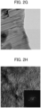
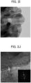
- FIG. 2I is a TEM image of 140,000 times magnification
- FIG. 2J is a TEM image of 1,400,000 times magnification.
- FIG. 3 shows the powder XRD (X-Ray Diffraction) patterns of Example 1 (V270-1), Example 2 (V270-2), Example 3 (V270-3) and Example 4 (V270-4).
- FIG. 4 is a view showing an outline of the change in internal structure in the case of firing VO 2 (C 2 O 4 ), which is the precursor.
- VO 2 C 2 O 4
- V 2 O 5 ⁇ 1.6H 2 O, V 6 O 13 and V 2 O 5 are mainly generated in the denitration catalyst, and a component other than these is amorphous V 2 O 5 .
- V 2 O 5 , V 2 O 5 ⁇ 1.6H 2 O, and V 6 O 13 are mainly generated in the denitration catalyst, and a component other than these is amorphous V 2 O 5 .
- V 2 O 5 is mainly generated in the denitration catalyst, and a component other than these is amorphous V 2 O 5 .
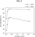
- the intensity ratio (P 6-13 /P 2-5 ) of the peak intensity (P 6-13 ) of the (110) plane of V 6 O 13 relative to the peak intensity (P 2-5 ) of the (001) plane of V 2 O 5 was calculated, and this was set as an index of each catalyst.
- Table 3 shows the intensity ratio of each vanadium catalyst, and the NOx conversion rates for both the case of a reaction temperature of 100°C and the case of a reaction temperature of 150°C.
- FIG. 5 is a plot graphing this Table 3.
- [Table 3] (Table 3) NO conversion rate of vanadium catalyst Sample Intensity Ratio NO conversion rate/% 100°C 150°C Example 1 (V270-1) 2.05 69 99
- Example 2 (V270-2) 0.32 79 100
- the color of the vanadium catalyst itself according to the above Examples and Comparative Examples changes from green to yellow as firing progresses.
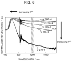
- Table 4 shows the absorption edge wavelength of each catalyst and the reflectance of wavelength 1200 nm.
- Table 4 (Table 4) Absorption edge wavelength and reflectance of vanadium catalyst Sample Absorption edge /nm Reflectance of 1200 nm /% Example 1 (V270-1) 537.4 15.7 Example 2 (V270-2) 70.0 81.3 Example 3 (V270-3) 547.0 Example 4 (V270-4) 554.7 90.1 Comparative Example 1 (V300-4) 537.4 94.3
- the NO conversion rates of catalysts according to the Examples having a reflectance of no more than 0.90 exhibited a higher value than the NO conversion rate of the catalyst according to the Comparative Example having a reflectance exceeding 0.90.
- an FT/IR-6100 infrared spectrometer manufactured by JASCO Corp. was used as the measurement apparatus.
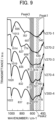
- FIG. 9 shows the spectral curve of each catalyst obtained as a result of measuring the infrared absorption spectra of the fingerprint region: 1150 to 400 cm -1 .
- FIG. 10 shows crystal structures of vanadium pentoxide according to each of the Examples.
- Example 11 is a graph establishing the ratio of P1/P3 in Table 5 as the horizontal axis, and establishing the NO conversion rate of each catalyst as the vertical axis.
- Table 5 (Table 5) Wavenumber and transmittance of each catalyst Sample Peak3 Peak2 Peak1 P1/P3 Wavenumber transmittance (%) Wavenumber transmittance (%) Wavenumber transmittance (%)
- Example 1 (V270-1) 604 37.6 542 31.0 0.83
- Example 2 (V270-2) 606 28.6 530 25.0 0.87
- Example 3 (V270-3) 613 35.2 516 37.9 474 38.5 1.09
- XPS X-ray photoelectron spectrum
- a JPS-9010MX photoelectron spectrometer manufactured by JEOL Ltd. was used as the measurement device.
- FIG. 12 shows the XPS spectra for the V2p region.
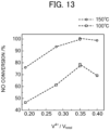
- FIG. 13 is a graph establishing the proportion of tetravalent vanadium in the overall vanadium of the catalyst surface of each of the Examples and Comparative Examples as the horizontal axis, and establishing the NO conversion rate as the vertical axis.
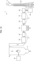
- FIG. 14 is a view showing the configuration of a combustion system 1 according to the first application example.
- the boiler 10 is formed in a substantially reversed U-shape as a whole.
- the exhaust gas produced in the boiler 10 moves in reverse U shape along the shape of the boiler 10.
- the coal pulverizer 20 preheats and dries the pulverized coal, by mixing the pulverized coal and air.
- the dust collector 50 is arranged on the downstream side of the gas heater 40 in the exhaust channel L1.
- the exhaust gas which was heat recovered in the gas heater 40 is supplied to the dust collector 50.
- the dust collector 50 is a device which collects dust such as coal ash (fly ash) in the exhaust gas by applying voltage to electrodes.
- the induced-draft fan 60 is arranged on the downstream side of the dust collector 50 in the exhaust channel L1.
- the desulfurization equipment 70 is arranged on the downstream side of the induced-draft fan 60 in the exhaust channel L1.
- the exhaust gas sent out from the induced-draft fan 60 is supplied to the desulfurization equipment 70.
- the desulfurization equipment 70 removes sulfur oxides from the exhaust gas, by absorbing sulfur oxides contained in the exhaust gas into a mixed solution, by spraying mixed solution (limestone slurry) of limestone and water to the exhaust gas.
- the temperature of exhaust gas in the desulfurization device 70 is 50 to 120°C, for example.
- the gas heater 80 is arranged on the downstream side of the desulfurization device 70 in the exhaust channel L1.
- the gas heater 80 heats the exhaust gas.
- the gas heater 80 heats the exhaust gas up to a temperature suited to the denitration reaction of the denitration device 90 at a later stage.
- the denitration device 90 is arranged on the downstream side of the gas heater 80 in the exhaust channel L1.
- the denitration device 90 removes nitrogen oxides from exhaust gas by a selective catalytic reduction process.
- the reductant used in the selective catalytic reduction process contains at least one of ammonia and urea.
- the exhaust gas from which nitrogen oxides were removed in the denitration device 90 is introduced to the smoke stack 100.
- FIG. 15 is a view showing the configuration of a combustion system 1A according to a second application example.
- the combustion system 1A is a combustion system establishing pulverized coal as fuel, similarly to the combustion system 1.
- combustion system 1A for constituent elements identical to the combustion system 1, the same reference numbers are used, and explanations of the functions thereof will be omitted.
- the induced-draft fan 60, desulfurization equipment 70, and a gas heater 80 are provided in order from upstream at the downstream of the denitration device 90.
- the gas heater 80 of the combustion system 1A heats the exhaust gas up to the suitable temperature to diffuse from the smoke stack 100 at a later stage.
- the downstream side of the exhaust channel L1 is connected to the smoke stack 100.
- the exhaust gas introduced to the smoke stack 100 is effectively discharged from the top of the smoke stack 100 by the stack effect.
- the temperature of exhaust gas near the outlet of the smoke stack 100 is 110°C, for example.
- the fuel supply device 110 supplies fuel using the fuel channel R1 to the internal combustion engine 120.
- the produced exhaust gas is discharged to the dust collector 130 via the exhaust channel R2.
- the gas turbine 142 and generator 144, and the steam turbine 143 and generator 144 are connected to each other.
- the generator 144 connected to the steam turbine 143 also operates in connection to perform power generation.
- the exhaust gas economizer 145 generates steam from water stored in a water supply tank (not illustrated), with the exhaust gas supplied from the dust collector 130 through the exhaust channel R2, and exhaust gas supplied from the gas turbine 142 through the exhaust channel R3 as the heat source.
- the steam generated by the exhaust gas economizer 145 is supplied to the steam turbine 143 through the steam channel R4.
- the steam channel R4 has an upstream side connected to the exhaust gas economizer 145, and a downstream side connected to the steam turbine 143.
- the denitration device 150 removes nitrogen oxides from the exhaust gas by way of the denitration catalyst.
- the denitration device 150 can be a configuration which injects ammonia gas to the introduced exhaust gas, and then contacts this mixed gas with the denitration catalyst.
- a fifth application example may be a denitration device which equips, to a combustion system that incinerates raw garbage, etc., a denitration catalyst containing vanadium oxide, and having a carbon content of at least 0.05 wt%, and the above denitration catalyst having a defect site at which an oxygen deficiency occurs in the crystal structure.
- the temperature of exhaust gas may be no more than 150°C, since the above-mentioned denitration catalyst can be used in denitration having a reaction temperature of 80 to 150°C, it is useful also for such a denitration system.
- the above-mentioned denitration catalyst is basically powder form; however, for example, a honeycomb-type catalyst made by coating catalyst component on a honeycomb shape substrate may be used in a flue gas denitration apparatus installed at a thermal power plant, as disclosed in Japanese Unexamined Patent Application, Publication No. 2005-199108 .
- any substrate can be used as the above-mentioned substrate.
- the substrate can be made into any form, and can be established as any among a plate-like shape, pellet shape, fluid form, columnar shape, star shape, ring shape, extruded shape, spherical shape, flake shape, pastille shape, rib extruded shape, or ribbed ring shape, for example.
- the weight ratio of the above-mentioned denitration catalyst in the catalyst block after firing becomes 100 wt%.
- the catalyst block by, after further mixing titanium molybdenum, tungsten and/or other compounds (particularly oxides), or silica, etc. to the above-mentioned denitration catalyst of powder form, then kneading, and extrusion molding.
- a combustion system is mentioned in 3.1
- a denitration catalyst made by coating the denitration component on a substrate is mentioned in 3.2
- a denitration catalyst molded into block form is mentioned in 3.3; however, the applications of the denitration catalyst are not limited thereto.
- a combustion system with pulverized coal as the fuel is mentioned in 3.1.1 and 3.1.2, and a combustion system with natural gas as the fuel is mentioned in 3.1.3; however, the above-mentioned denitration catalyst may be used in a combustion system using oil or biomass fuel in place of pulverized coal or natural gas.
- the combustion system 1 according to the above application example arranged the denitration device 90 on the downstream side of the dust collector 50, in the exhaust channel L1 through which exhaust gas generated in the boiler (combustion device) 10 flows.
- the denitration device 90 is not arranged upstream of the air preheater 30 which is normally arranged near the boiler (combustion device) 10 in the exhaust channel L1, clogging of the air preheater 30 caused by ammonium sulfate produced by ammonia and sulfur component in exhaust gas reacting will not occur.
- the combustion system 1A according to the above embodiment can exhibit an effect whereby the denitration efficiency at low temperature is even higher compared to the conventional technology, upon selective catalytic reduction reaction with ammonia as the reductant.
- the exhaust heat recovery device 140 it is preferable for the exhaust heat recovery device 140 to include the turbine device 141 and exhaust gas economizer 145, in which the exhaust gas economizer 145 produces steam with exhaust gas discharged from the internal combustion engine 120 and exhaust gas supplied from the turbine device 141 as heat sources, and the turbine device 141 conducts power generation using the exhaust gas discharged from the internal combustion engine 120 and steam supplied from the exhaust gas economizer 145.
- the exhaust heat recovery device 140 in the above embodiment can more effectively use the heat energy generated by combustion of fuel in the internal combustion engine 120, by including the turbine device 141 and exhaust gas economizer 145.
Landscapes
- Engineering & Computer Science (AREA)
- Chemical & Material Sciences (AREA)
- Chemical Kinetics & Catalysis (AREA)
- Mechanical Engineering (AREA)
- General Engineering & Computer Science (AREA)
- Combustion & Propulsion (AREA)
- Materials Engineering (AREA)
- Organic Chemistry (AREA)
- Health & Medical Sciences (AREA)
- Toxicology (AREA)
- Environmental & Geological Engineering (AREA)
- Physics & Mathematics (AREA)
- Thermal Sciences (AREA)
- Biomedical Technology (AREA)
- Analytical Chemistry (AREA)
- General Chemical & Material Sciences (AREA)
- Oil, Petroleum & Natural Gas (AREA)
- Exhaust Gas Treatment By Means Of Catalyst (AREA)
- Catalysts (AREA)
- Chimneys And Flues (AREA)
Claims (2)
- Verbrennungssystem (1, 1A, 1C), aufweisend:eine Verbrennungsvorrichtung (10, 120), die einen Kraftstoff verbrennt;einen Abgaskanal (L1, R2), durch den Abgas strömt, das durch den Kraftstoff erzeugt wird, der in der Verbrennungsvorrichtung (10, 120) verbrannt wird;einen Staubabscheider (50, 130), der in dem Abgaskanal (L1, R2) angeordnet ist und Aschestaub in dem Abgas sammelt; undeine Denitrierungsvorrichtung (90, 150), die in dem Abgaskanal (L1, P2) angeordnet ist und mittels eines Denitrierungskatalysators Stickoxide aus dem Abgas entfernt,wobei die Denitrierungsvorrichtung (90, 150) auf einer stromabwärts befindlichen Seite des Staubabscheiders (50, 130) in dem Abgaskanal (L1, R2) angeordnet ist, wobei der Denitrierungskatalysator Vanadiumoxid enthält und das Vanadiumoxid Vanadiumpentoxid umfasst,dadurch gekennzeichnet, dassder Denitrierungskatalysator Defektstellen aufweist, an denen Sauerstoffatome in der Kristallstruktur des Vanadiumpentoxids fehlen,und dass das Vorhandensein von Defektstellen, an denen Sauerstoffatome fehlen, anzeigt, dass ein Intensitätsverhältnis der Peak-Intensität (P6-13) auf der (110)-Ebene von V6O13 relativ zur Peak-Intensität (P2-5) auf der (001)-Ebene von V2O5, durch Pulver-Röntgenstrahlbeugung des Denitrierungskatalysators ermittelt, mindestens 0,08 und höchstens 2,05 beträgt.
- Verbrennungssystem (1, 1A, 1C) nach Anspruch 1, wobei das Verbrennungssystem (1, 1A) darüber hinaus einen Luftvorwärmer (30) umfasst, der in dem Abgaskanal (L1) angeordnet ist und Wärme aus dem Abgas zurückgewinnt, und
wobei der Luftvorwärmer (30) auf einer stromaufwärts befindlichen Seite des Staubabscheiders (50) angeordnet ist.
Applications Claiming Priority (1)
| Application Number | Priority Date | Filing Date | Title |
|---|---|---|---|
| PCT/JP2019/009204 WO2020179079A1 (ja) | 2019-03-07 | 2019-03-07 | 燃焼システム |
Publications (3)
| Publication Number | Publication Date |
|---|---|
| EP3936765A1 EP3936765A1 (de) | 2022-01-12 |
| EP3936765A4 EP3936765A4 (de) | 2022-10-26 |
| EP3936765B1 true EP3936765B1 (de) | 2025-04-16 |
Family
ID=72338468
Family Applications (1)
| Application Number | Title | Priority Date | Filing Date |
|---|---|---|---|
| EP19917753.6A Active EP3936765B1 (de) | 2019-03-07 | 2019-03-07 | Verbrennungssystem mit einem denitrierungskatalysator |
Country Status (5)
| Country | Link |
|---|---|
| US (1) | US11560819B2 (de) |
| EP (1) | EP3936765B1 (de) |
| JP (1) | JP7315922B2 (de) |
| CN (1) | CN113841009A (de) |
| WO (1) | WO2020179079A1 (de) |
Families Citing this family (1)
| Publication number | Priority date | Publication date | Assignee | Title |
|---|---|---|---|---|
| SG11202109723RA (en) * | 2019-03-07 | 2021-10-28 | The Chugoku Electric Power Co Inc | Denitration catalyst and method for producing same |
Family Cites Families (21)
| Publication number | Priority date | Publication date | Assignee | Title |
|---|---|---|---|---|
| JPS5474270A (en) | 1977-11-25 | 1979-06-14 | Mitsubishi Chem Ind Ltd | Nitrogen oxide decpomosition |
| JPS5738939A (en) * | 1980-08-19 | 1982-03-03 | Ishikawajima Harima Heavy Ind Co Ltd | Catalyst for treatment of nitrogen oxide and its production |
| JPS6041903A (ja) * | 1983-08-18 | 1985-03-05 | 株式会社丸和エコ− | スーツケースの製造方法 |
| JPH1157469A (ja) * | 1997-08-08 | 1999-03-02 | Mitsubishi Heavy Ind Ltd | 脱硝触媒 |
| JPH11342337A (ja) * | 1998-06-02 | 1999-12-14 | Tokyo Gas Co Ltd | 窒素酸化物の分解除去用触媒b及び窒素酸化物の分解除去方法 |
| JP2000197822A (ja) * | 1999-01-08 | 2000-07-18 | Tokyo Gas Co Ltd | 窒素酸化物の分解除去用触媒及び窒素酸化物の分解除去方法 |
| JP4578048B2 (ja) | 2002-06-21 | 2010-11-10 | 中国電力株式会社 | 脱硝触媒再生方法 |
| JP2004275852A (ja) | 2003-03-14 | 2004-10-07 | Mitsubishi Heavy Ind Ltd | 排煙脱硝触媒及びその製造方法 |
| US7820590B2 (en) * | 2003-09-27 | 2010-10-26 | Korea Power Engineering Company, Inc. | Method for preparing vanadium/titania-based catalyst for removing nitrogen oxide at low temperature |
| JP5216189B2 (ja) * | 2005-12-22 | 2013-06-19 | 株式会社キャタラー | 排ガス浄化用触媒 |
| US20120070763A1 (en) | 2009-05-11 | 2012-03-22 | Showa Denko K.K. | Catalyst, production process therefor and use thereof |
| JP2012047094A (ja) * | 2010-08-26 | 2012-03-08 | Mitsubishi Heavy Ind Ltd | 舶用脱硝システムおよびこれを備えた船舶ならびに舶用脱硝システムの制御方法 |
| EP2755764B1 (de) | 2012-08-17 | 2016-07-27 | Johnson Matthey Public Limited Company | Zeolithdotierter v/ti/w katalysator |
| JP5863885B2 (ja) * | 2014-06-06 | 2016-02-17 | 三菱日立パワーシステムズ株式会社 | ボイラシステムおよびそれを備えた発電プラント |
| WO2016023121A1 (en) * | 2014-08-12 | 2016-02-18 | Noram Engineering And Constructors Ltd. | Gas treatment process and apparatus |
| JP6627312B2 (ja) | 2015-07-31 | 2020-01-08 | 中国電力株式会社 | 石炭火力発電設備 |
| JP6077190B1 (ja) * | 2015-09-08 | 2017-02-08 | 中国電力株式会社 | 火力発電システム |
| WO2018047356A1 (ja) | 2016-09-12 | 2018-03-15 | 中国電力株式会社 | 脱硝触媒、及びその製造方法 |
| US10655518B2 (en) * | 2017-02-21 | 2020-05-19 | General Electric Company | Systems for reducing startup emissions in power plant including gas turbine |
| JP6467117B1 (ja) | 2017-04-25 | 2019-02-06 | 鈴豊精鋼株式会社 | 多孔性触媒、燃料電池用触媒層、電極、膜電極接合体、及び燃料電池、並びに多孔性触媒の製造方法 |
| CN108554398B (zh) * | 2018-05-31 | 2021-04-20 | 武汉理工大学 | 一种宽温度窗口脱硝催化剂的制备方法及其应用 |
-
2019
- 2019-03-07 US US17/436,940 patent/US11560819B2/en active Active
- 2019-03-07 WO PCT/JP2019/009204 patent/WO2020179079A1/ja not_active Ceased
- 2019-03-07 EP EP19917753.6A patent/EP3936765B1/de active Active
- 2019-03-07 JP JP2019538447A patent/JP7315922B2/ja active Active
- 2019-03-07 CN CN201980093704.9A patent/CN113841009A/zh active Pending
Also Published As
| Publication number | Publication date |
|---|---|
| US20220127991A1 (en) | 2022-04-28 |
| US11560819B2 (en) | 2023-01-24 |
| JP7315922B2 (ja) | 2023-07-27 |
| WO2020179079A1 (ja) | 2020-09-10 |
| JPWO2020179079A1 (de) | 2020-09-10 |
| EP3936765A4 (de) | 2022-10-26 |
| CN113841009A (zh) | 2021-12-24 |
| EP3936765A1 (de) | 2022-01-12 |
Similar Documents
| Publication | Publication Date | Title |
|---|---|---|
| US10519837B2 (en) | Combustion system | |
| US20220170403A1 (en) | Combustion system | |
| EP3936766B1 (de) | Verbrennungssystem mit einem vanadiumoxid-denitrierungskatalysator | |
| WO2010116531A1 (ja) | Coシフト触媒、coシフト反応装置及びガス化ガスの精製方法 | |
| KR20190068189A (ko) | 선택적 촉매환원반응용 저온 탈질촉매 및 그 제조방법 | |
| CN103619467A (zh) | 具有改善的抗中毒性能的催化剂 | |
| US11560819B2 (en) | Combustion system | |
| WO2010131358A1 (ja) | Coシフト触媒及びその製造方法、並びにcoシフト触媒を用いたcoシフト反応装置 | |
| JPH11342337A (ja) | 窒素酸化物の分解除去用触媒b及び窒素酸化物の分解除去方法 | |
| JP7587225B2 (ja) | 燃焼システム | |
| EP3936227A1 (de) | Denitrierungskatalysator und verfahren zur herstellung davon | |
| KR20060120317A (ko) | 배기가스의 미세 입자상 물질 제거용 산화촉매 및 이를이용한 제거 방법 |
Legal Events
| Date | Code | Title | Description |
|---|---|---|---|
| STAA | Information on the status of an ep patent application or granted ep patent |
Free format text: STATUS: THE INTERNATIONAL PUBLICATION HAS BEEN MADE |
|
| PUAI | Public reference made under article 153(3) epc to a published international application that has entered the european phase |
Free format text: ORIGINAL CODE: 0009012 |
|
| STAA | Information on the status of an ep patent application or granted ep patent |
Free format text: STATUS: REQUEST FOR EXAMINATION WAS MADE |
|
| 17P | Request for examination filed |
Effective date: 20211005 |
|
| AK | Designated contracting states |
Kind code of ref document: A1 Designated state(s): AL AT BE BG CH CY CZ DE DK EE ES FI FR GB GR HR HU IE IS IT LI LT LU LV MC MK MT NL NO PL PT RO RS SE SI SK SM TR |
|
| DAV | Request for validation of the european patent (deleted) | ||
| DAX | Request for extension of the european patent (deleted) | ||
| REG | Reference to a national code |
Ref country code: DE Ref legal event code: R079 Free format text: PREVIOUS MAIN CLASS: F23J0015000000 Ipc: B01D0053860000 Ref document number: 602019068878 Country of ref document: DE |
|
| A4 | Supplementary search report drawn up and despatched |
Effective date: 20220927 |
|
| RIC1 | Information provided on ipc code assigned before grant |
Ipc: F01N 3/08 20060101ALI20220921BHEP Ipc: F23J 15/06 20060101ALI20220921BHEP Ipc: B01J 37/08 20060101ALI20220921BHEP Ipc: B01J 37/02 20060101ALI20220921BHEP Ipc: B01J 35/10 20060101ALI20220921BHEP Ipc: B01J 35/00 20060101ALI20220921BHEP Ipc: B01J 23/22 20060101ALI20220921BHEP Ipc: B01D 53/94 20060101ALI20220921BHEP Ipc: F23J 15/02 20060101ALI20220921BHEP Ipc: F23J 15/00 20060101ALI20220921BHEP Ipc: B01D 53/86 20060101AFI20220921BHEP |
|
| STAA | Information on the status of an ep patent application or granted ep patent |
Free format text: STATUS: EXAMINATION IS IN PROGRESS |
|
| 17Q | First examination report despatched |
Effective date: 20240523 |
|
| GRAP | Despatch of communication of intention to grant a patent |
Free format text: ORIGINAL CODE: EPIDOSNIGR1 |
|
| STAA | Information on the status of an ep patent application or granted ep patent |
Free format text: STATUS: GRANT OF PATENT IS INTENDED |
|
| RIC1 | Information provided on ipc code assigned before grant |
Ipc: F01N 13/00 20100101ALI20241022BHEP Ipc: F01N 5/02 20060101ALI20241022BHEP Ipc: F01N 3/20 20060101ALI20241022BHEP Ipc: F01N 3/021 20060101ALI20241022BHEP Ipc: F23J 15/00 20060101ALI20241022BHEP Ipc: F23J 15/02 20060101ALI20241022BHEP Ipc: B01J 35/30 20240101ALI20241022BHEP Ipc: B01D 53/94 20060101ALI20241022BHEP Ipc: B01J 23/22 20060101ALI20241022BHEP Ipc: B01J 35/00 20060101ALI20241022BHEP Ipc: B01J 37/02 20060101ALI20241022BHEP Ipc: B01J 37/08 20060101ALI20241022BHEP Ipc: F23J 15/06 20060101ALI20241022BHEP Ipc: F01N 3/08 20060101ALI20241022BHEP Ipc: B01D 53/86 20060101AFI20241022BHEP |
|
| INTG | Intention to grant announced |
Effective date: 20241118 |
|
| RIN1 | Information on inventor provided before grant (corrected) |
Inventor name: INOMATA YUSUKE Inventor name: HATA SHINICHI Inventor name: HARUTA MASATAKE Inventor name: MURAYAMA TORU Inventor name: MORITA KEIICHIRO Inventor name: YOSHIDA KAZUHIRO Inventor name: KIYONAGA EIJI |
|
| GRAS | Grant fee paid |
Free format text: ORIGINAL CODE: EPIDOSNIGR3 |
|
| GRAA | (expected) grant |
Free format text: ORIGINAL CODE: 0009210 |
|
| STAA | Information on the status of an ep patent application or granted ep patent |
Free format text: STATUS: THE PATENT HAS BEEN GRANTED |
|
| AK | Designated contracting states |
Kind code of ref document: B1 Designated state(s): AL AT BE BG CH CY CZ DE DK EE ES FI FR GB GR HR HU IE IS IT LI LT LU LV MC MK MT NL NO PL PT RO RS SE SI SK SM TR |
|
| REG | Reference to a national code |
Ref country code: GB Ref legal event code: FG4D |
|
| REG | Reference to a national code |
Ref country code: CH Ref legal event code: EP Ref country code: DE Ref legal event code: R096 Ref document number: 602019068878 Country of ref document: DE |
|
| REG | Reference to a national code |
Ref country code: IE Ref legal event code: FG4D |
|
| REG | Reference to a national code |
Ref country code: NL Ref legal event code: MP Effective date: 20250416 |
|
| PG25 | Lapsed in a contracting state [announced via postgrant information from national office to epo] |
Ref country code: NL Free format text: LAPSE BECAUSE OF FAILURE TO SUBMIT A TRANSLATION OF THE DESCRIPTION OR TO PAY THE FEE WITHIN THE PRESCRIBED TIME-LIMIT Effective date: 20250416 |
|
| REG | Reference to a national code |
Ref country code: AT Ref legal event code: MK05 Ref document number: 1785211 Country of ref document: AT Kind code of ref document: T Effective date: 20250416 |
|
| PG25 | Lapsed in a contracting state [announced via postgrant information from national office to epo] |
Ref country code: ES Free format text: LAPSE BECAUSE OF FAILURE TO SUBMIT A TRANSLATION OF THE DESCRIPTION OR TO PAY THE FEE WITHIN THE PRESCRIBED TIME-LIMIT Effective date: 20250416 Ref country code: PT Free format text: LAPSE BECAUSE OF FAILURE TO SUBMIT A TRANSLATION OF THE DESCRIPTION OR TO PAY THE FEE WITHIN THE PRESCRIBED TIME-LIMIT Effective date: 20250818 Ref country code: FI Free format text: LAPSE BECAUSE OF FAILURE TO SUBMIT A TRANSLATION OF THE DESCRIPTION OR TO PAY THE FEE WITHIN THE PRESCRIBED TIME-LIMIT Effective date: 20250416 |
|
| REG | Reference to a national code |
Ref country code: LT Ref legal event code: MG9D |
|
| PG25 | Lapsed in a contracting state [announced via postgrant information from national office to epo] |
Ref country code: NO Free format text: LAPSE BECAUSE OF FAILURE TO SUBMIT A TRANSLATION OF THE DESCRIPTION OR TO PAY THE FEE WITHIN THE PRESCRIBED TIME-LIMIT Effective date: 20250716 Ref country code: GR Free format text: LAPSE BECAUSE OF FAILURE TO SUBMIT A TRANSLATION OF THE DESCRIPTION OR TO PAY THE FEE WITHIN THE PRESCRIBED TIME-LIMIT Effective date: 20250717 |
|
| PG25 | Lapsed in a contracting state [announced via postgrant information from national office to epo] |
Ref country code: PL Free format text: LAPSE BECAUSE OF FAILURE TO SUBMIT A TRANSLATION OF THE DESCRIPTION OR TO PAY THE FEE WITHIN THE PRESCRIBED TIME-LIMIT Effective date: 20250416 |
|
| PG25 | Lapsed in a contracting state [announced via postgrant information from national office to epo] |
Ref country code: BG Free format text: LAPSE BECAUSE OF FAILURE TO SUBMIT A TRANSLATION OF THE DESCRIPTION OR TO PAY THE FEE WITHIN THE PRESCRIBED TIME-LIMIT Effective date: 20250416 |
|
| PG25 | Lapsed in a contracting state [announced via postgrant information from national office to epo] |
Ref country code: HR Free format text: LAPSE BECAUSE OF FAILURE TO SUBMIT A TRANSLATION OF THE DESCRIPTION OR TO PAY THE FEE WITHIN THE PRESCRIBED TIME-LIMIT Effective date: 20250416 |
|
| PG25 | Lapsed in a contracting state [announced via postgrant information from national office to epo] |
Ref country code: AT Free format text: LAPSE BECAUSE OF FAILURE TO SUBMIT A TRANSLATION OF THE DESCRIPTION OR TO PAY THE FEE WITHIN THE PRESCRIBED TIME-LIMIT Effective date: 20250416 |
|
| PG25 | Lapsed in a contracting state [announced via postgrant information from national office to epo] |
Ref country code: RS Free format text: LAPSE BECAUSE OF FAILURE TO SUBMIT A TRANSLATION OF THE DESCRIPTION OR TO PAY THE FEE WITHIN THE PRESCRIBED TIME-LIMIT Effective date: 20250716 |
|
| PG25 | Lapsed in a contracting state [announced via postgrant information from national office to epo] |
Ref country code: IS Free format text: LAPSE BECAUSE OF FAILURE TO SUBMIT A TRANSLATION OF THE DESCRIPTION OR TO PAY THE FEE WITHIN THE PRESCRIBED TIME-LIMIT Effective date: 20250816 |
|
| PG25 | Lapsed in a contracting state [announced via postgrant information from national office to epo] |
Ref country code: LV Free format text: LAPSE BECAUSE OF FAILURE TO SUBMIT A TRANSLATION OF THE DESCRIPTION OR TO PAY THE FEE WITHIN THE PRESCRIBED TIME-LIMIT Effective date: 20250416 |
|
| PG25 | Lapsed in a contracting state [announced via postgrant information from national office to epo] |
Ref country code: SM Free format text: LAPSE BECAUSE OF FAILURE TO SUBMIT A TRANSLATION OF THE DESCRIPTION OR TO PAY THE FEE WITHIN THE PRESCRIBED TIME-LIMIT Effective date: 20250416 Ref country code: DK Free format text: LAPSE BECAUSE OF FAILURE TO SUBMIT A TRANSLATION OF THE DESCRIPTION OR TO PAY THE FEE WITHIN THE PRESCRIBED TIME-LIMIT Effective date: 20250416 |
|
| REG | Reference to a national code |
Ref country code: DE Ref legal event code: R097 Ref document number: 602019068878 Country of ref document: DE |
|
| PG25 | Lapsed in a contracting state [announced via postgrant information from national office to epo] |
Ref country code: CZ Free format text: LAPSE BECAUSE OF FAILURE TO SUBMIT A TRANSLATION OF THE DESCRIPTION OR TO PAY THE FEE WITHIN THE PRESCRIBED TIME-LIMIT Effective date: 20250416 |
|
| PG25 | Lapsed in a contracting state [announced via postgrant information from national office to epo] |
Ref country code: EE Free format text: LAPSE BECAUSE OF FAILURE TO SUBMIT A TRANSLATION OF THE DESCRIPTION OR TO PAY THE FEE WITHIN THE PRESCRIBED TIME-LIMIT Effective date: 20250416 |
|
| PG25 | Lapsed in a contracting state [announced via postgrant information from national office to epo] |
Ref country code: SK Free format text: LAPSE BECAUSE OF FAILURE TO SUBMIT A TRANSLATION OF THE DESCRIPTION OR TO PAY THE FEE WITHIN THE PRESCRIBED TIME-LIMIT Effective date: 20250416 Ref country code: RO Free format text: LAPSE BECAUSE OF FAILURE TO SUBMIT A TRANSLATION OF THE DESCRIPTION OR TO PAY THE FEE WITHIN THE PRESCRIBED TIME-LIMIT Effective date: 20250416 |
|
| PG25 | Lapsed in a contracting state [announced via postgrant information from national office to epo] |
Ref country code: IT Free format text: LAPSE BECAUSE OF FAILURE TO SUBMIT A TRANSLATION OF THE DESCRIPTION OR TO PAY THE FEE WITHIN THE PRESCRIBED TIME-LIMIT Effective date: 20250416 |
|
| PLBE | No opposition filed within time limit |
Free format text: ORIGINAL CODE: 0009261 |
|
| STAA | Information on the status of an ep patent application or granted ep patent |
Free format text: STATUS: NO OPPOSITION FILED WITHIN TIME LIMIT |
|
| REG | Reference to a national code |
Ref country code: CH Ref legal event code: L10 Free format text: ST27 STATUS EVENT CODE: U-0-0-L10-L00 (AS PROVIDED BY THE NATIONAL OFFICE) Effective date: 20260225 |
|
| 26N | No opposition filed |
Effective date: 20260119 |
|
| PGFP | Annual fee paid to national office [announced via postgrant information from national office to epo] |
Ref country code: DE Payment date: 20260128 Year of fee payment: 8 |
|
| PGFP | Annual fee paid to national office [announced via postgrant information from national office to epo] |
Ref country code: BE Payment date: 20260217 Year of fee payment: 8 |