EP3936732B1 - Threaded timepiece member - Google Patents
Threaded timepiece member Download PDFInfo
- Publication number
- EP3936732B1 EP3936732B1 EP20185189.6A EP20185189A EP3936732B1 EP 3936732 B1 EP3936732 B1 EP 3936732B1 EP 20185189 A EP20185189 A EP 20185189A EP 3936732 B1 EP3936732 B1 EP 3936732B1
- Authority
- EP
- European Patent Office
- Prior art keywords
- timepiece
- timepiece member
- threading
- thread
- standard
- Prior art date
- Legal status (The legal status is an assumption and is not a legal conclusion. Google has not performed a legal analysis and makes no representation as to the accuracy of the status listed.)
- Active
Links
- 239000000919 ceramic Substances 0.000 claims description 38
- 239000000463 material Substances 0.000 claims description 37
- 229910052751 metal Inorganic materials 0.000 claims description 31
- 239000002184 metal Substances 0.000 claims description 31
- MCMNRKCIXSYSNV-UHFFFAOYSA-N Zirconium dioxide Chemical compound O=[Zr]=O MCMNRKCIXSYSNV-UHFFFAOYSA-N 0.000 claims description 30
- 229910052594 sapphire Inorganic materials 0.000 claims description 14
- 239000010980 sapphire Substances 0.000 claims description 14
- 239000011521 glass Substances 0.000 claims description 12
- 229910001092 metal group alloy Inorganic materials 0.000 claims description 8
- BEIGFKLRGRRJJA-JLHYYAGUSA-O 2-(2f-benzothiazolyl)-5-styryl-3-(4f-phthalhydrazidyl)tetrazolium chloride Chemical compound C=1C=C2C(=O)NNC(=O)C2=CC=1[N+](N(N=1)C=2SC3=CC=CC=C3N=2)=NC=1\C=C\C1=CC=CC=C1 BEIGFKLRGRRJJA-JLHYYAGUSA-O 0.000 claims description 3
- 239000011248 coating agent Substances 0.000 claims description 3
- 238000000576 coating method Methods 0.000 claims description 3
- 239000010935 stainless steel Substances 0.000 description 7
- 229910001220 stainless steel Inorganic materials 0.000 description 7
- 230000000712 assembly Effects 0.000 description 6
- 238000000429 assembly Methods 0.000 description 6
- 238000007789 sealing Methods 0.000 description 6
- 206010010904 Convulsion Diseases 0.000 description 5
- 239000007769 metal material Substances 0.000 description 4
- 238000000034 method Methods 0.000 description 3
- 238000011282 treatment Methods 0.000 description 3
- 229920000297 Rayon Polymers 0.000 description 2
- RTAQQCXQSZGOHL-UHFFFAOYSA-N Titanium Chemical compound [Ti] RTAQQCXQSZGOHL-UHFFFAOYSA-N 0.000 description 2
- 241001639412 Verres Species 0.000 description 2
- 229910052782 aluminium Inorganic materials 0.000 description 2
- XAGFODPZIPBFFR-UHFFFAOYSA-N aluminium Chemical compound [Al] XAGFODPZIPBFFR-UHFFFAOYSA-N 0.000 description 2
- PNEYBMLMFCGWSK-UHFFFAOYSA-N aluminium oxide Inorganic materials [O-2].[O-2].[O-2].[Al+3].[Al+3] PNEYBMLMFCGWSK-UHFFFAOYSA-N 0.000 description 2
- 230000006835 compression Effects 0.000 description 2
- 238000007906 compression Methods 0.000 description 2
- 238000005336 cracking Methods 0.000 description 2
- 238000009434 installation Methods 0.000 description 2
- 238000005461 lubrication Methods 0.000 description 2
- 230000004048 modification Effects 0.000 description 2
- 238000012986 modification Methods 0.000 description 2
- 210000000056 organ Anatomy 0.000 description 2
- 239000002964 rayon Substances 0.000 description 2
- 230000009467 reduction Effects 0.000 description 2
- 230000035939 shock Effects 0.000 description 2
- 239000000126 substance Substances 0.000 description 2
- 239000010936 titanium Substances 0.000 description 2
- 229910052719 titanium Inorganic materials 0.000 description 2
- 229910000505 Al2TiO5 Inorganic materials 0.000 description 1
- 229910052581 Si3N4 Inorganic materials 0.000 description 1
- 239000004809 Teflon Substances 0.000 description 1
- 229920006362 Teflon® Polymers 0.000 description 1
- 230000001154 acute effect Effects 0.000 description 1
- 229910000808 amorphous metal alloy Inorganic materials 0.000 description 1
- 230000008901 benefit Effects 0.000 description 1
- 238000005524 ceramic coating Methods 0.000 description 1
- 229910010293 ceramic material Inorganic materials 0.000 description 1
- 238000002468 ceramisation Methods 0.000 description 1
- 238000004140 cleaning Methods 0.000 description 1
- 239000002131 composite material Substances 0.000 description 1
- 230000008602 contraction Effects 0.000 description 1
- PMHQVHHXPFUNSP-UHFFFAOYSA-M copper(1+);methylsulfanylmethane;bromide Chemical compound Br[Cu].CSC PMHQVHHXPFUNSP-UHFFFAOYSA-M 0.000 description 1
- 230000007797 corrosion Effects 0.000 description 1
- 238000005260 corrosion Methods 0.000 description 1
- 230000000694 effects Effects 0.000 description 1
- PCHJSUWPFVWCPO-UHFFFAOYSA-N gold Chemical compound [Au] PCHJSUWPFVWCPO-UHFFFAOYSA-N 0.000 description 1
- 239000010931 gold Substances 0.000 description 1
- 229910052737 gold Inorganic materials 0.000 description 1
- 238000010438 heat treatment Methods 0.000 description 1
- 230000000977 initiatory effect Effects 0.000 description 1
- 229910052500 inorganic mineral Inorganic materials 0.000 description 1
- 230000010354 integration Effects 0.000 description 1
- 230000002427 irreversible effect Effects 0.000 description 1
- 239000000314 lubricant Substances 0.000 description 1
- 230000005389 magnetism Effects 0.000 description 1
- 238000004519 manufacturing process Methods 0.000 description 1
- 238000005259 measurement Methods 0.000 description 1
- 230000007246 mechanism Effects 0.000 description 1
- 239000011707 mineral Substances 0.000 description 1
- 150000004767 nitrides Chemical class 0.000 description 1
- 238000005457 optimization Methods 0.000 description 1
- AABBHSMFGKYLKE-SNAWJCMRSA-N propan-2-yl (e)-but-2-enoate Chemical compound C\C=C\C(=O)OC(C)C AABBHSMFGKYLKE-SNAWJCMRSA-N 0.000 description 1
- 230000008439 repair process Effects 0.000 description 1
- 230000000284 resting effect Effects 0.000 description 1
- 238000010079 rubber tapping Methods 0.000 description 1
- HBMJWWWQQXIZIP-UHFFFAOYSA-N silicon carbide Chemical compound [Si+]#[C-] HBMJWWWQQXIZIP-UHFFFAOYSA-N 0.000 description 1
- 229910010271 silicon carbide Inorganic materials 0.000 description 1
- HQVNEWCFYHHQES-UHFFFAOYSA-N silicon nitride Chemical compound N12[Si]34N5[Si]62N3[Si]51N64 HQVNEWCFYHHQES-UHFFFAOYSA-N 0.000 description 1
- 238000004513 sizing Methods 0.000 description 1
- 239000004575 stone Substances 0.000 description 1
- 238000004381 surface treatment Methods 0.000 description 1
- 238000007751 thermal spraying Methods 0.000 description 1
- UONOETXJSWQNOL-UHFFFAOYSA-N tungsten carbide Chemical compound [W+]#[C-] UONOETXJSWQNOL-UHFFFAOYSA-N 0.000 description 1
Images


Classifications
-
- G—PHYSICS
- G04—HOROLOGY
- G04B—MECHANICALLY-DRIVEN CLOCKS OR WATCHES; MECHANICAL PARTS OF CLOCKS OR WATCHES IN GENERAL; TIME PIECES USING THE POSITION OF THE SUN, MOON OR STARS
- G04B37/00—Cases
- G04B37/0008—Cases for pocket watches and wrist watches
-
- G—PHYSICS
- G04—HOROLOGY
- G04B—MECHANICALLY-DRIVEN CLOCKS OR WATCHES; MECHANICAL PARTS OF CLOCKS OR WATCHES IN GENERAL; TIME PIECES USING THE POSITION OF THE SUN, MOON OR STARS
- G04B39/00—Watch crystals; Fastening or sealing of crystals; Clock glasses
-
- G—PHYSICS
- G04—HOROLOGY
- G04B—MECHANICALLY-DRIVEN CLOCKS OR WATCHES; MECHANICAL PARTS OF CLOCKS OR WATCHES IN GENERAL; TIME PIECES USING THE POSITION OF THE SUN, MOON OR STARS
- G04B37/00—Cases
- G04B37/22—Materials or processes of manufacturing pocket watch or wrist watch cases
- G04B37/223—Materials or processes of manufacturing pocket watch or wrist watch cases metallic cases coated with a nonmetallic layer
-
- F—MECHANICAL ENGINEERING; LIGHTING; HEATING; WEAPONS; BLASTING
- F16—ENGINEERING ELEMENTS AND UNITS; GENERAL MEASURES FOR PRODUCING AND MAINTAINING EFFECTIVE FUNCTIONING OF MACHINES OR INSTALLATIONS; THERMAL INSULATION IN GENERAL
- F16B—DEVICES FOR FASTENING OR SECURING CONSTRUCTIONAL ELEMENTS OR MACHINE PARTS TOGETHER, e.g. NAILS, BOLTS, CIRCLIPS, CLAMPS, CLIPS OR WEDGES; JOINTS OR JOINTING
- F16B31/00—Screwed connections specially modified in view of tensile load; Break-bolts
- F16B31/02—Screwed connections specially modified in view of tensile load; Break-bolts for indicating the attainment of a particular tensile load or limiting tensile load
-
- F—MECHANICAL ENGINEERING; LIGHTING; HEATING; WEAPONS; BLASTING
- F16—ENGINEERING ELEMENTS AND UNITS; GENERAL MEASURES FOR PRODUCING AND MAINTAINING EFFECTIVE FUNCTIONING OF MACHINES OR INSTALLATIONS; THERMAL INSULATION IN GENERAL
- F16B—DEVICES FOR FASTENING OR SECURING CONSTRUCTIONAL ELEMENTS OR MACHINE PARTS TOGETHER, e.g. NAILS, BOLTS, CIRCLIPS, CLAMPS, CLIPS OR WEDGES; JOINTS OR JOINTING
- F16B33/00—Features common to bolt and nut
- F16B33/006—Non-metallic fasteners using screw-thread
-
- F—MECHANICAL ENGINEERING; LIGHTING; HEATING; WEAPONS; BLASTING
- F16—ENGINEERING ELEMENTS AND UNITS; GENERAL MEASURES FOR PRODUCING AND MAINTAINING EFFECTIVE FUNCTIONING OF MACHINES OR INSTALLATIONS; THERMAL INSULATION IN GENERAL
- F16B—DEVICES FOR FASTENING OR SECURING CONSTRUCTIONAL ELEMENTS OR MACHINE PARTS TOGETHER, e.g. NAILS, BOLTS, CIRCLIPS, CLAMPS, CLIPS OR WEDGES; JOINTS OR JOINTING
- F16B33/00—Features common to bolt and nut
- F16B33/02—Shape of thread; Special thread-forms
- F16B33/04—Shape of thread; Special thread-forms in view of tensile load
-
- G—PHYSICS
- G04—HOROLOGY
- G04B—MECHANICALLY-DRIVEN CLOCKS OR WATCHES; MECHANICAL PARTS OF CLOCKS OR WATCHES IN GENERAL; TIME PIECES USING THE POSITION OF THE SUN, MOON OR STARS
- G04B37/00—Cases
- G04B37/08—Hermetic sealing of openings, joints, passages or slits
- G04B37/10—Hermetic sealing of openings, joints, passages or slits of winding stems
- G04B37/103—Hermetic sealing of openings, joints, passages or slits of winding stems by screwing the crown onto the case
-
- G—PHYSICS
- G04—HOROLOGY
- G04B—MECHANICALLY-DRIVEN CLOCKS OR WATCHES; MECHANICAL PARTS OF CLOCKS OR WATCHES IN GENERAL; TIME PIECES USING THE POSITION OF THE SUN, MOON OR STARS
- G04B39/00—Watch crystals; Fastening or sealing of crystals; Clock glasses
- G04B39/002—Watch crystals; Fastening or sealing of crystals; Clock glasses made of glass
-
- G—PHYSICS
- G04—HOROLOGY
- G04B—MECHANICALLY-DRIVEN CLOCKS OR WATCHES; MECHANICAL PARTS OF CLOCKS OR WATCHES IN GENERAL; TIME PIECES USING THE POSITION OF THE SUN, MOON OR STARS
- G04B39/00—Watch crystals; Fastening or sealing of crystals; Clock glasses
- G04B39/004—Watch crystals; Fastening or sealing of crystals; Clock glasses from a material other than glass
- G04B39/006—Watch crystals; Fastening or sealing of crystals; Clock glasses from a material other than glass out of wear resistant material, e.g. sapphire
-
- F—MECHANICAL ENGINEERING; LIGHTING; HEATING; WEAPONS; BLASTING
- F16—ENGINEERING ELEMENTS AND UNITS; GENERAL MEASURES FOR PRODUCING AND MAINTAINING EFFECTIVE FUNCTIONING OF MACHINES OR INSTALLATIONS; THERMAL INSULATION IN GENERAL
- F16B—DEVICES FOR FASTENING OR SECURING CONSTRUCTIONAL ELEMENTS OR MACHINE PARTS TOGETHER, e.g. NAILS, BOLTS, CIRCLIPS, CLAMPS, CLIPS OR WEDGES; JOINTS OR JOINTING
- F16B33/00—Features common to bolt and nut
-
- G—PHYSICS
- G04—HOROLOGY
- G04B—MECHANICALLY-DRIVEN CLOCKS OR WATCHES; MECHANICAL PARTS OF CLOCKS OR WATCHES IN GENERAL; TIME PIECES USING THE POSITION OF THE SUN, MOON OR STARS
- G04B3/00—Normal winding of clockworks by hand or mechanically; Winding up several mainsprings or driving weights simultaneously
- G04B3/04—Rigidly-mounted keys, knobs or crowns
-
- G—PHYSICS
- G04—HOROLOGY
- G04B—MECHANICALLY-DRIVEN CLOCKS OR WATCHES; MECHANICAL PARTS OF CLOCKS OR WATCHES IN GENERAL; TIME PIECES USING THE POSITION OF THE SUN, MOON OR STARS
- G04B37/00—Cases
- G04B37/0008—Cases for pocket watches and wrist watches
- G04B37/0033—Cases for pocket watches and wrist watches with cover or bottom which can slide or turn (without a spring action)
Definitions
- the invention relates to a threaded member for a timepiece.
- the invention also relates to a timepiece case comprising such a threaded member.
- the invention also relates to a timepiece comprising such a threaded member and/or such a timepiece case.
- the casing of watches is subject to numerous constraints, in particular sealing, robustness, appearance, and must be carried out in such a way as to prevent any involuntary dismantling resulting irremediably in an after-sales intervention for the replacement of seals. , cleaning, lubrication, even repair.
- fragile materials such as ceramics, glass, sapphire, etc. have very good compressive strength but poor tensile strength. This is why threaded systems made of fragile materials are not considered suitable for assemblies subjected to substantial tensile stress. For example, when the tightening torque is too high, tensile and/or shear stresses are generated on the thread resulting in cracking, or even breaking of the latter.
- Timepieces are already known whose case includes one or more covering elements made of a natural or synthetic hard mineral material such as sapphire, ceramic, natural or reconstituted stone, etc. These materials are not ductile and have little capacity to absorb a shock by deforming. This implies a resistance to tensile stresses lower than that of parts of the same geometry in metal. In general, this low resistance to tensile stresses is not compatible with the stresses undergone by the part (assembly, overpressure, etc.).
- the assembly of a metal back on a metal caseband is traditionally done by screwing as described among other things in the documents CH1359773 And CH486059 .
- the threads are standardized and both internal and external threads are made to the same standard with the largest possible thread contact area.
- a metal back assembled with a metal caseband is generally lubricated and tightened with a torque of between 1 and 6 N.m.
- Such a bottom can moreover be required to withstand overpressures, in particular during dives.
- the thread of a bottom made of fragile material should withstand the same tightening torque, i.e. 1 and 6 Nm It should also withstand overpressures depending on the degree of sealing envisaged (eg sealing up to 50m, 100m, 1220m or 3900m).
- Self-locking threaded assembly systems are also known, such as that described in the document WO2013/072389 whose nominal diameter is less than 1.5mm and whose threaded element has a second thread whose longitudinal section has an asymmetrical profile pitch.
- the assembly corresponds in particular to the standards of Swiss watchmaking (NIHS) and to the internal standards of watchmakers.
- NIHS Swiss watchmaking
- the continuous contact between the elements of the assembly makes it possible to distribute the tensile forces over the total length of the thread of the threaded parts in contact and therefore to reduce the fatigue of the screw/nut system.
- the threads are defined there by their profile, which incorporates the diameters of the part (external, internal diameter, etc.), the angle of the profile, the pitch, and if applicable the helix angle.
- Various standards describe the form of a thread, including the angle of the thread profile, the pitch and the diameter of the thread, for example NIHS 60-30, ISO (for example EN 10226-1 or ISO 261), UN (for example ASME B1.1), Whitworth, British Standard (BSPT), American National, Pipe Threads, NPT, NPTF, DIN 405, MJ, UNJ, etc.
- the complete designation gives the values corresponding to the shape of the thread and the tolerances.
- the section of a thread with NIHS, ISO, and UN thread profiles is similar to an equilateral triangle, that is, the flanks of the threads are at 60 degrees (angle between flanks).
- the thread flanks form an angle of 55 degrees.
- the assemblies of ceramic components on metal components are generally made by means other than screwing within the ceramic, or else the screwing is made more reliable by the integration of metal threaded sleeves within the ceramic part.
- the document EP0520224 describes a watch case comprising a metal middle part and a ceramic back.
- the ceramic back is fixed to the middle by means of screws, the screws being screwed, through the back, into tappings made in the middle.
- the document EP1916576 describes a watch case comprising a metal middle part and a ceramic back.
- the ceramic back 1 is held on the caseband by means of a threaded metal clamping ring.
- EP3276432 describes an assembly suitable for attaching a ceramic or sapphire back to a ceramic or metal caseband, in particular gold. He discloses that a person skilled in the art is of the opinion that the very low ductility of ceramic materials does not allow standard fixing methods, in particular direct screwing. To overcome this problem, this document proposes a connection with a specific geometry of the bayonet type compressing a ring. The choice of ring material determines the maximum tightening torque. For example, a ring an amorphous alloy allows a tightening torque of around 3.2 Nm, similar to the usual torque for a caseback screwed onto a caseband, for a joint of the same size.
- the Apple company offers watches with a case (for example, aluminum) and a cover (carrying biometric sensors) made of ceramic, sapphire or reinforced glass (ion-X).
- the lid is "clipped” and held in place with a Teflon gasket.
- a threaded (or screwed) assembly system also referred to as a "threaded system” is commonly used to attach two or more parts together.
- a threaded system is provided to ensure the durability of the assembly throughout its lifetime. Its interest stems in particular from its simplicity (the assembly elements are part of the parts to be assembled), its disassembly and the applications which result therefrom.
- a threaded system consists of a first threaded element, for example in the form of a screw, and a second threaded element, for example in the form of a nut, and its installation consists of the association of the screw and nut to which a tightening torque is applied during the screwing operation. Tightening the nut on the screw compresses the parts to be assembled. The screw is thus prestressed. The axial force to which it is subjected is called tension. During screwing, a tightening torque is applied to the screw which allows the helical movement of the latter in the nut and which, when the parts are in contact, forces the elongation of the screw and thus its tensioning. In such a screwing mode, the voltage induced by tightening the nut on the screw is therefore linked to the torque applied to the nut. The relationship between voltage and torque is related to many parameters.
- the elements of the threaded system thus undergo different types of mechanical stresses, for example in tension, in compression, in shear, etc.
- the object of the invention is to provide a threaded clockwork member making it possible to improve the members known from the prior art and to remedy the aforementioned drawbacks.
- the invention proposes a threaded timepiece, reliable and made of fragile material.
- the invention allows the easy replacement of a metal component by a ceramic component without requiring modification of the design of the second component with which the ceramic component is intended to cooperate. It also makes it possible to keep the same assembly/disassembly tools as those developed for the assembly of metal components.
- a timepiece according to the invention is defined by claim 1.
- a timepiece case according to the invention is defined by claim 9.
- Embodiments of a timepiece case are defined by claims 10 and 11.
- a timepiece according to the invention is defined by claim 12.
- the timepiece 200 is for example a watch, in particular a wristwatch.
- Timepiece 200 includes a timepiece box or case 100.
- the timepiece box 100 is intended to receive a movement in order to protect it from the external environment.
- the box is preferably waterproof.
- the watch movement can be an electronic movement or a mechanical movement, in particular an automatic movement.
- the timepiece case comprises a first member 10 or first component and a second member 20 or second component intended to be assembled together by screwing.
- each of the two members comprises a thread and one of the two members is screwed into the other, by cooperation of the two threads.
- the two threads therefore have the same pitch and, more generally, dimensional characteristics allowing them to cooperate with each other.
- Each thread comprises one or more threads and generally has a helical shape around the axis A10.
- Each thread is a helical portion whose length measured along the axis is equal to the pitch.
- the bottom of the thread 15 is the junction between two flanks 16 of adjacent threads.
- the thread flanks 16, that is to say the sides of the threads, correspond to the parts located between the top 14 and the bottoms 15 of the net.
- the top 14 of the thread is the portion where the two flanks 16 of the same thread meet.
- the first thread 11 has a first thread angle 12
- the second thread 21 has a second thread angle 22
- the value of the first thread angle 12 is 2 to 4 degrees greater than the value of the second thread angle. 22.
- a thread angle is defined as the angle formed by the two flanks of a thread at an axial cut of the thread.
- one of the threads has a suitable thread angle, so that the flanks of the first thread of the first member are, as seen above, resting or in contact against the flanks of the second thread of the second member, at contact zones extending as close as possible to the bottoms of the threads of the first thread.
- the contact zones extend at most over a distance (measured radially relative to the axis A10) less than h/2 or less than h/4 or less than h/8 with h corresponding to the height of the threads of the first thread or at the height of the threads of the first thread.
- the difference in thread angle of the first and second threads must not significantly impact the behavior of the assembly, for example holding, sealing, seizing, etc.
- an increase of 2° to 4° in the thread angle of the first thread compared to the angle specified in the standard makes it possible to reduce the tensile stresses as demonstrated by the calculations of the inventors.
- the thread angle of the first thread is then between 62° and 64°. With such a dimensioning, the contact between the thread flanks of the first member and the thread flanks of the second member is located in the lower part of the flanks of the first thread, close to the root of the thread of the first member.
- the threads of the first thread may have truncations such that the vertices of the axial sections of the threads of the first thread have a rectilinear or convex shape.
- the first thread has a thread root radius r greater than 0.2 times the pitch of the first thread or greater than 0.4 times the pitch of the first thread.
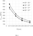
- the optimization of the radius r of the root 15 of the thread also makes it possible to participate in the reduction of the tensile stresses in the first member, as illustrated in the graphs of the figure 2 And 3 .
- FIG. 2 illustrates, for a zirconia caseback assembled with a stainless steel caseband comprising a standardized thread (ISO standard), the impact of the thread root radius on the stress undergone by the caseback threading, for different caseback thread angles.
- ISO standard standardized thread
- the first thread is connected to a bearing surface 5 via a connection fillet 13 having a radius greater than 0.4 times the pitch p of the first thread or greater than 0.8 times the pitch p of the first thread.
- This bearing surface extends radially outwards from the first thread and is intended to bear against a second surface 25 provided on the second timepiece.
- a gasket can be arranged between these two surfaces in order to provide a seal between the two members.
- the connecting fillet 13 is part of a groove, that is a cavity which has two groove walls and a groove bottom, and which ensures the connection between the support plane 5 and the first thread 11.
- a first groove wall can have a straight, curved or a combination of the two.
- the curvature can be defined by a groove radius 18a.
- Side bearing surface 5 the groove wall can have a straight axial section, curved or a combination of both.
- the curvature can be defined by a groove radius 18b.
- the bottom of the groove may have a point axial section, that is to say its axial section may be the point of intersection of the axial sections of the two groove walls.
- the bottom of the groove may be more extensive as shown in the figure 1 where two curved portions 18a and 18b are connected by a straight section portion.
- the first member also undergoes tensile stresses in the vicinity of this groove.
- the first metal members For components of the watch case type, typically for back-middle assemblies, the first metal members have groove radii on the thread side 18a and on the bearing surface side 18b of between 0.06 mm and 0.15 mm. Nominally, they are 0.05 mm.
- the groove radii on the thread 18a side and the support plane 18b side can be identical or different.
- connection angle between the groove and the bearing surface can be straight, acute or obtuse, with or without stitching in the material.
- connection between the groove and the bearing surface can be flat or recessed without affecting the tensile strength of the groove.
- the second thread 21 is preferably standardized.
- the second thread may be a standardized thread according to an ISO standard or according to an NIHS standard or according to a UN standard or according to a BSPT standard or according to an NPT standard or according to an NPTF standard or according to a DIN standard or according to an MJ standard. or according to a UNJ standard or according to a Whitworth profile.
- the first thread is an external or external thread, that is to say that it is made on a projecting surface, for example on a surface of a shaft.
- the second thread is an internal or internal thread, that is to say it is made on a recessed surface, for example on a surface of a bore.
- the first member is a bottom made of fragile material, in particular ceramic or sapphire or zirconia or glass, the first thread of which is subjected to tensile stresses.
- the back is assembled to a second member which is a middle part.
- This middle part is made of a more ductile material, in particular a metallic material or a metallic alloy.
- the invention can be transposed to any other type of screwing where a first member made of fragile material, in particular ceramic or sapphire or zirconia or glass, cooperates with a second member made of a more ductile material, in particular a metallic material or metal alloy, to make an assembly.
- the invention can also be transposed to any other type of screwing where a first member made of fragile material, in particular ceramic or sapphire or zirconia or glass, cooperates with a second member made of fragile material, in particular ceramic or sapphire or zirconia or glass, to make an assembly.
- the first and second members are screwed together so that they are mechanically constrained, the member constituting the screw being for example mechanically constrained in traction.
- charts make it possible to determine the limit value to adopt before damage of the screw-nut couple for predetermined dimensions in a given material and in a given normative reference frame. These charts do not exist for material pairs involving metal alloys and fragile materials such as ceramic, sapphire, zirconia or glass.
- the seizing threshold of a pair of materials is defined by the value of the contact pressure at which material is transferred from one surface to the other. There is a seizure threshold for each pair of materials. In addition to the surface condition, this threshold depends on the chemical and/or metallurgical nature of each of the two materials in contact.
- seizing can occur in two stages: micro-seizing, followed, if necessary, by total seizing.
- Micro-seizing appears when the tension no longer increases linearly but in stages while the tightening torque increases. These are, for example, micro-welds caused then broken by the tightening torque applied as and when they occur (“stick-slip” phenomenon). A relative rotation remains possible between the elements but the tightening is disturbed. This phenomenon can be localized.
- micro-seizing increases with the increase in the tightening torque until total seizing. When there is total seizure, all rotation is blocked.
- a prestressed threaded assembly remains removable as long as no seizing occurs between the members after tightening. This implies that to guarantee the disassembly of a threaded assembly, certain precautions are necessary, among other things to avoid any micro-seizing during initial tightening, to avoid any corrosion during service and to maintain a correct coefficient of friction during the life of the assembly.
- Stainless steel, aluminum and titanium threads are particularly prone to galling.
- stainless steel assemblies are generally treated, for example with a lubricant or an “anti-seize” coating. These treatments are likely to be degraded over time.
- a ceramic member for example made of zirconia, according to the invention has a lower probability of seizing than a metal member which it replaces.
- a zirconia component with a tightening torque of 5 N.m, no seizing or deformation was observed, even without treatment of the metal part.
- the system also supports higher tightening torques without seizing. For example, a torque of 10 N.m was applied to a zirconia caseback according to the invention, assembled on a stainless steel caseband, without initiating seizing or deformation of the components, even without treatment of the metal part.
- the thread may be a ceramized metal thread, that is to say a thread whose thread surfaces consist of a ceramic coating.
- the ceramization can be obtained by thermal spraying of a ceramic, by surface treatment, by heat treatment or by any other suitable technique.
- the invention makes it possible to minimize the risks of cracking or chipping of the ceramic layer as well as those of seizing of the assembly.
- the base material is, for example, stainless steel, titanium, etc.
- the ceramic layer is for example in oxidized ceramic (zirconia, alumina, aluminum titanate, etc.) or in non-oxidized ceramic such as a nitride or a carbide (aluminum nitride, silicon nitride, silicon carbide, tungsten carbide, etc). '
- bottoms in fragile materials or in metal alloy having the same geometries or substantially the same geometries and which can be interchanged to cooperate with the same middle part, in particular the same metal middle part. Furthermore, these bottoms can be mounted without the need to modify the production tools or after-sales service for the assembly/dismantling of the bottom, regardless of the material in which the bottom is made.
- a waterproof wristwatch case comprising a bottom made of fragile material, in particular ceramic, in sapphire, zirconia or glass, replacing a metal back without adapting the metal middle.
- the invention it is possible to modify the thread of the bottom made of fragile material in order to preserve its integrity during screwing, in a tightening and use condition identical to that of a metal bottom.
- the seizing problems encountered with metal heads are avoided, even with higher tightening torques than those usually used with metal alloy heads.
- a thread of a member made of fragile type material so that the thread resists the same ranges of stresses as a metal part that the member replaces and so that the thread is compatible with standard threads, for example threads according to Swiss watchmaking standards (NIHS).
- NIHS Swiss watchmaking standards
- This design thus advantageously allows the easy replacement of a metal bottom by a ceramic bottom without the need to modify the design of the metal part that receives it and/or the bottom assembly/disassembly tools, while guaranteeing proper sealing, secure assembly and minimizing the risk of seizing.
- the external and internal threads are machined according to the same class with the same tolerance, in order to be compatible and to maximize the contact surface between the external and internal threads.
- the flanks of the internal thread and the flanks of the external thread are in contact over the largest possible surface, the flanks being as "flat” as possible.
- the first and second members are advantageously linked by a threaded connection, or assembled to each other by screwing.
- a timepiece comprises such an assembly.
Description
L'invention concerne un organe fileté pour pièce d'horlogerie. L'invention concerne aussi une boîte de pièce d'horlogerie comprenant un tel organe fileté. L'invention concerne encore une pièce d'horlogerie comprenant un tel organe fileté et/ou une telle boîte de pièce d'horlogerie.The invention relates to a threaded member for a timepiece. The invention also relates to a timepiece case comprising such a threaded member. The invention also relates to a timepiece comprising such a threaded member and/or such a timepiece case.
L'habillage des montres obéit à de nombreuses contraintes, en particulier d'étanchéité, de robustesse, d'aspect, et doit être réalisé de façon à prévenir tout démontage involontaire se traduisant irrémédiablement par une intervention d'après-vente pour échange de joints, nettoyage, lubrification, voire réparation.The casing of watches is subject to numerous constraints, in particular sealing, robustness, appearance, and must be carried out in such a way as to prevent any involuntary dismantling resulting irremediably in an after-sales intervention for the replacement of seals. , cleaning, lubrication, even repair.
Pour les pièces dont le comportement mécanique est de type fragile, par exemple en céramique (zircone, alumine, composites, etc.), en verre, en saphir, etc... devant assurer l'étanchéité et/ou devant pouvoir être assemblées et désassemblées, par exemple les fonds ou les mailles de bracelet, il est considéré que les modes d'assemblage traditionnels ne sont pas adaptés.For parts whose mechanical behavior is of the fragile type, for example in ceramic (zirconia, alumina, composites, etc.), in glass, in sapphire, etc., which must ensure sealing and/or must be able to be assembled and disassembled, for example the backs or bracelet links, it is considered that traditional assembly methods are not suitable.
En effet, les matériaux fragiles, comme la céramique, le verre, le saphir, etc... ont une très bonne résistance en compression mais une mauvaise résistance en traction. C'est pourquoi on considère les systèmes filetés en matériaux fragiles comme non adaptés pour des assemblages soumis à une sollicitation en traction conséquente. Par exemple, lorsque le couple de serrage est trop important, des contraintes en traction et/ou en cisaillement sont générées sur le filetage entraînant une fissuration, voir une rupture de ce dernier.Indeed, fragile materials, such as ceramics, glass, sapphire, etc... have very good compressive strength but poor tensile strength. This is why threaded systems made of fragile materials are not considered suitable for assemblies subjected to substantial tensile stress. For example, when the tightening torque is too high, tensile and/or shear stresses are generated on the thread resulting in cracking, or even breaking of the latter.
Leur usage est de ce fait essentiellement limité aux domaines mettant à profit les autres caractéristiques de la céramique (résistance chimique, tenue aux températures extrêmes, amagnétisme, biocompatibilité, etc...) avec des contraintes mécaniques limitées.Their use is therefore essentially limited to areas that take advantage of the other characteristics of ceramics (chemical resistance, resistance to extreme temperatures, non-magnetism, biocompatibility, etc.) with limited mechanical stresses.
On connaît déjà des pièces d'horlogerie dont le boîtier comporte un ou plusieurs éléments d'habillage réalisé(s) en un matériau minéral dur naturel ou synthétique tel que le saphir, la céramique, une pierre naturelle ou reconstituée, etc. Ces matériaux ne sont pas ductiles et n'ont que peu de capacité à amortir un choc en se déformant. Ceci implique une résistance aux contraintes de traction inférieure à celle de pièces de même géométrie en métal. En général, cette faible résistance aux contraintes de traction n'est pas compatible avec les contraintes subies par la pièce (assemblage, surpression, etc.).Timepieces are already known whose case includes one or more covering elements made of a natural or synthetic hard mineral material such as sapphire, ceramic, natural or reconstituted stone, etc. These materials are not ductile and have little capacity to absorb a shock by deforming. This implies a resistance to tensile stresses lower than that of parts of the same geometry in metal. In general, this low resistance to tensile stresses is not compatible with the stresses undergone by the part (assembly, overpressure, etc.).
L'assemblage d'un fond métallique sur une carrure métallique se fait traditionnellement par vissage comme décrit entre autre dans les documents
Pour garantir la sécurisation du montage et minimiser les risques de grippage, un fond métallique assemblé avec une carrure métallique est en général lubrifié et serré avec un couple compris entre 1 et 6 N.m. Un tel fond peut de plus être amené à supporter des surpressions, notamment lors de plongées.To guarantee assembly security and minimize the risk of seizure, a metal back assembled with a metal caseband is generally lubricated and tightened with a torque of between 1 and 6 N.m. Such a bottom can moreover be required to withstand overpressures, in particular during dives.
Afin de garantir que l'on puisse utiliser les mêmes outils de montage/démontage que pour des fonds métalliques, le filetage d'un fond en matériau fragile devrait résister au même couple de serrage, c'est-à-dire 1 et 6 N.m. Il devrait également supporter des surpressions en fonction du degré d'étanchéité envisagé (p.ex. étanchéité jusqu'à 50m, 100m, 1220m ou 3900m).In order to guarantee that the same assembly/disassembly tools can be used as for metal bottoms, the thread of a bottom made of fragile material should withstand the same tightening torque, i.e. 1 and 6 Nm It should also withstand overpressures depending on the degree of sealing envisaged (eg sealing up to 50m, 100m, 1220m or 3900m).
Si un filetage en céramique est réalisé selon les normes standards, les contraintes de traction générées par le serrage et/ou la surpression dépassent la résistance de la céramique, entraînant des déformations irréversibles, des fissurations, voire une rupture, en particulier au niveau des filets.If a ceramic thread is made according to standard standards, the tensile stresses generated by the tightening and/or the overpressure exceed the resistance of the ceramic, leading to irreversible deformations, cracks, or even breakage, in particular at the level of the threads. .
On connaît également des systèmes d'assemblage fileté autobloquant comme celui décrit dans le document
Pour garantir que les deux parties d'un assemblage fileté (interne et externe) s'adaptent correctement et supportent une charge spécifiée, les filets doivent respecter certaines normes. Les filetages y sont définis par leur profil, qui incorpore les diamètres de la pièce (diamètre extérieur, intérieur, etc.), l'angle du profil, le pas, et le cas échéant l'angle d'hélice.To ensure that the two parts of a threaded joint (internal and external) fit properly and support a specified load, the threads must meet certain standards. The threads are defined there by their profile, which incorporates the diameters of the part (external, internal diameter, etc.), the angle of the profile, the pitch, and if applicable the helix angle.
Diverses normes décrivent la forme d'un filetage, notamment l'angle du profil de filets, le pas et le diamètre du filetage, par exemple NIHS 60-30, ISO (par exemple EN 10226-1 ou ISO 261), UN (par exemple ASME B1.1), Whitworth, British Standard (BSPT), American National, Pipe Threads, NPT, NPTF, DIN 405, MJ, UNJ, etc.Various standards describe the form of a thread, including the angle of the thread profile, the pitch and the diameter of the thread, for example NIHS 60-30, ISO (for example EN 10226-1 or ISO 261), UN (for example ASME B1.1), Whitworth, British Standard (BSPT), American National, Pipe Threads, NPT, NPTF, DIN 405, MJ, UNJ, etc.
La désignation complète donne les valeurs correspondant à la forme du filet et les tolérances.The complete designation gives the values corresponding to the shape of the thread and the tolerances.
Par exemple, la section d'un filetage présentant des profils de filet NIHS, ISO et UN s'apparente à un triangle équilatéral, c'est-à-dire que les flancs des filets sont à 60 degrés (angle entre flancs). Pour les filetages Whitworth, les flancs de filets forment un angle de 55 degrés.For example, the section of a thread with NIHS, ISO, and UN thread profiles is similar to an equilateral triangle, that is, the flanks of the threads are at 60 degrees (angle between flanks). For Whitworth threads, the thread flanks form an angle of 55 degrees.
Les assemblages de composants en céramique sur des composants métalliques sont généralement réalisés par d'autres moyens que le vissage au sein de la céramique, ou alors le vissage est fiabilisé par l'intégration de douilles filetées métalliques au sein de la pièce en céramique.The assemblies of ceramic components on metal components are generally made by means other than screwing within the ceramic, or else the screwing is made more reliable by the integration of metal threaded sleeves within the ceramic part.
Le document
Le document
Le document
La société Apple propose des montres avec un boîtier (par exemple en aluminium) et un couvercle (portant des capteurs biométriques) en céramique, en saphir ou en verre renforcé (ion-X). Le couvercle est « clipsé » et maintenu avec un joint d'étanchéité en téflon.The Apple company offers watches with a case (for example, aluminum) and a cover (carrying biometric sensors) made of ceramic, sapphire or reinforced glass (ion-X). The lid is "clipped" and held in place with a Teflon gasket.
En outre, un système d'assemblage par filetage (ou vissage), également désigné par « système fileté », est couramment utilisé pour fixer au moins deux pièces l'une à l'autre. Un tel système fileté est prévu pour assurer la pérennité de l'assemblage tout au long de sa durée de vie. Son intérêt provient notamment de sa simplicité (les éléments d'assemblage font partie des pièces à assembler), de sa démontabilité et des applications qui en découlent.In addition, a threaded (or screwed) assembly system, also referred to as a "threaded system", is commonly used to attach two or more parts together. Such a threaded system is provided to ensure the durability of the assembly throughout its lifetime. Its interest stems in particular from its simplicity (the assembly elements are part of the parts to be assembled), its disassembly and the applications which result therefrom.
De façon générale, un système fileté se compose d'un premier élément fileté par exemple sous la forme d'une vis et d'un deuxième élément fileté par exemple sous la forme d'un écrou, et son installation consiste en l'association de la vis et de l'écrou pour laquelle est appliqué un couple de serrage lors de l'opération de vissage. Le serrage de l'écrou sur la vis permet de comprimer les pièces à assembler. La vis est ainsi précontrainte. L'effort axial, auquel elle est soumise, est appelé tension. Lors du vissage, on applique un couple de serrage à la vis qui permet le mouvement hélicoïdal de celle-ci dans l'écrou et qui, lorsque les pièces sont en contact, force l'allongement de la vis et ainsi sa mise en tension. Dans un tel mode de vissage, la tension induite par serrage de l'écrou sur la vis est donc liée au couple appliqué à l'écrou. La relation entre la tension et le couple est liée à de nombreux paramètres.In general, a threaded system consists of a first threaded element, for example in the form of a screw, and a second threaded element, for example in the form of a nut, and its installation consists of the association of the screw and nut to which a tightening torque is applied during the screwing operation. Tightening the nut on the screw compresses the parts to be assembled. The screw is thus prestressed. The axial force to which it is subjected is called tension. During screwing, a tightening torque is applied to the screw which allows the helical movement of the latter in the nut and which, when the parts are in contact, forces the elongation of the screw and thus its tensioning. In such a screwing mode, the voltage induced by tightening the nut on the screw is therefore linked to the torque applied to the nut. The relationship between voltage and torque is related to many parameters.
Les éléments du système fileté subissent ainsi différents types de contraintes mécaniques, par exemple en traction, en compression, en cisaillement, etc.The elements of the threaded system thus undergo different types of mechanical stresses, for example in tension, in compression, in shear, etc.
Le but de l'invention est de fournir un organe horloger fileté permettant d'améliorer les organes connus de l'art antérieur et de remédier aux inconvénients mentionnés précédemment. En particulier, l'invention propose un organe horloger fileté, fiable et réalisé en matériau fragile.The object of the invention is to provide a threaded clockwork member making it possible to improve the members known from the prior art and to remedy the aforementioned drawbacks. In particular, the invention proposes a threaded timepiece, reliable and made of fragile material.
L'invention permet le remplacement aisé d'un composant métallique par un composant en céramique sans nécessiter de modifier la conception du deuxième composant avec lequel le composant en céramique est destiné à coopérer. Elle permet en outre de conserver les mêmes outils de montage/démontage que ceux développés pour l'assemblage des composants métalliques.The invention allows the easy replacement of a metal component by a ceramic component without requiring modification of the design of the second component with which the ceramic component is intended to cooperate. It also makes it possible to keep the same assembly/disassembly tools as those developed for the assembly of metal components.
Un organe horloger selon l'invention est défini par la revendication 1.A timepiece according to the invention is defined by claim 1.
Différents modes de réalisation de l'organe horloger sont définis par les revendications 2 à 8.Different embodiments of the timepiece are defined by claims 2 to 8.
Une boîte de pièce d'horlogerie selon l'invention est définie par la revendication 9.A timepiece case according to the invention is defined by claim 9.
Des modes de réalisation de boîte de pièce d'horlogerie sont définis par les revendications 10 et 11.Embodiments of a timepiece case are defined by
Une pièce d'horlogerie selon l'invention est définie par la revendication 12.A timepiece according to the invention is defined by
Les dessins annexés représentent, à titre d'exemple, un mode de réalisation d'une pièce d'horlogerie.
- La
figure 1 représente un premier mode de réalisation d'une pièce d'horlogerie. - La
figure 2 illustre les évolutions d'une contrainte maximale dans un fond (S1max), en fonction du rayon de fond de filet du fond (R), pour différents angles de filet du fond. - La
figure 3 illustre les évolutions d'une contrainte maximale dans un fond (S1max), en fonction du rayon de fond de filet du fond (R), pour différents assemblages ayant des caractéristiques d'angles de filet du fond et de filet de la carrure variées.
- There
figure 1 represents a first embodiment of a timepiece. - There
picture 2 illustrates the changes in a maximum stress in a bottom (S 1max ), as a function of the bottom thread root radius (R), for different bottom thread angles. - There
figure 3 illustrates the evolutions of a maximum stress in a caseback (S 1max ), as a function of the caseback caseback caseback radius (R), for different assemblies having varied backcase caseback case and middle case case case angle characteristics .
Un mode de réalisation d'une pièce d'horlogerie 200 est décrit ci-après en référence à la
La pièce d'horlogerie 200 est par exemple une montre, en particulier une montre bracelet.The
La pièce d'horlogerie 200 comprend une boîte ou un boîtier 100 de pièce d'horlogerie. La boîte 100 de pièce d'horlogerie est destinée à recevoir un mouvement afin de le protéger de l'environnement extérieur. La boîte est de préférence étanche.
Le mouvement horloger peut être un mouvement électronique ou un mouvement mécanique, notamment un mouvement automatique.The watch movement can be an electronic movement or a mechanical movement, in particular an automatic movement.
La boîte de pièce d'horlogerie comprend un premier organe 10 ou premier composant et un deuxième organe 20 ou deuxième composant destinés à être assemblés l'un à l'autre par vissage. Autrement dit, chacun des deux organes comprend un filetage et l'un des deux organes est vissé dans l'autre, par coopération des deux filetages. Les deux filetages présentent donc un même pas et, plus généralement, des caractéristiques dimensionnelles leur permettant de coopérer l'un avec l'autre.The timepiece case comprises a
Le premier organe horloger 10 comprend un premier axe A10 et un premier filetage 11 présentant un pas p et destiné à coopérer avec un deuxième filetage 21 prévu sur le deuxième organe horloger 20. Le premier filetage est :
- conformé ou configuré de sorte qu'une zone de contact C entre le premier filetage et le deuxième filetage s'étend sur moins de 50% de la hauteur h des filets du deuxième filetage, voire sur moins de 30% de la hauteur h des filets du deuxième filetage ; voire sur moins de 15% de la hauteur h des filets du deuxième filetage, ou
- conformé ou configuré de sorte que la zone de contact C entre le premier filetage et le deuxième filetage s'étend sur moins de 0.3 fois le pas p, voire sur moins de 0.2 fois le pas p, voire sur moins de 0.1 fois le pas p, l'étendue e de la zone de contact C étant mesurée radialement relativement au premier axe A10 depuis le fond 15 des filets du premier filetage.
- shaped or configured so that a contact zone C between the first thread and the second thread extends over less than 50% of the height h of the threads of the second thread, or even over less than 30% of the height h of the threads of the second thread; even on less than 15% of the height h of the threads of the second thread, or
- shaped or configured so that the contact zone C between the first threading and the second threading extends over less than 0.3 times the pitch p, even over less than 0.2 times the pitch p, even over less than 0.1 times the pitch p , the extent e of the contact zone C being measured radially relative to the first axis A10 from the bottom 15 of the threads of the first thread.
Ces caractéristiques géométriques sont vérifiées de préférence sur l'intégralité ou sur la quasi-intégralité ou sur la majorité des portions de filetages qui sont en contact. Autrement, dit ces caractéristiques ne sont pas seulement vérifiées ponctuellement au niveau d'une portion d'interface de vissage entre les premier et deuxième organes.These geometric characteristics are preferably verified on all or almost all or on the majority of the portions of threads which are in contact. In other words, these characteristics are not only verified punctually at a screwing interface portion between the first and second members.
Chaque filetage comprend un ou plusieurs filets et a globalement une forme hélicoïdale autour de l'axe A10. Chaque filet est une portion hélicoïdale dont la longueur mesurée selon l'axe vaut le pas. Le fond du filet 15 est la jonction entre deux flancs 16 de filets adjacents. Les flancs 16 de filet, c'est-à-dire les côtés des filets, correspondent aux parties situées entre le sommet 14 et les fonds 15 de filet. Le sommet 14 du filet est la portion où les deux flancs 16 d'un même filet se rejoignent.Each thread comprises one or more threads and generally has a helical shape around the axis A10. Each thread is a helical portion whose length measured along the axis is equal to the pitch. The bottom of the
De préférence, le premier filetage 11 présente un premier angle de filet 12, le deuxième filetage 21 présente un deuxième angle de filet 22 et la valeur du premier angle de filet 12 est supérieure de 2 à 4 degrés à la valeur du deuxième angle de filet 22. Un angle de filet est défini comme l'angle que forment les deux flancs d'un filet au niveau d'une coupe axiale du filetage.Preferably, the
En adaptant le dimensionnement du filetage du premier organe et/ou du deuxième organe, on peut proposer un assemblage du premier organe en matériau fragile avec le deuxième organe dont le filetage est normalisé.By adapting the dimensioning of the thread of the first member and/or of the second member, it is possible to propose an assembly of the first member made of fragile material with the second member whose thread is standardized.
Alors qu'un filetage selon l'art antérieur est conçu afin de maximiser la surface d'appui des deux filetages pour mieux répartir les différentes forces au niveau des interfaces lors de l'assemblage, avec pour conséquence que les flancs de filets des deux organes sont le plus parallèles possible, dans ce mode de réalisation, un des filetages présente un angle de filet adapté, afin que les flancs du premier filetage du premier organe soient, comme vu précédemment, en appui ou en contact contre les flancs du deuxième filetage du deuxième organe, au niveau de zones de contact s'étendant au plus près des fonds des filets du premier filetage. De préférence, les zones de contact s'étendent au plus sur une distance (mesurée radialement relativement à l'axe A10) inférieure à h/2 ou inférieure à h/4 ou inférieure à h/8 avec h correspondant à la hauteur des filets du premier filetage ou à la hauteur des filets du premier filetage.While a thread according to the prior art is designed to maximize the bearing surface of the two threads to better distribute the different forces at the interfaces during assembly, with the consequence that the thread flanks of the two members are as parallel as possible, in this embodiment, one of the threads has a suitable thread angle, so that the flanks of the first thread of the first member are, as seen above, resting or in contact against the flanks of the second thread of the second member, at contact zones extending as close as possible to the bottoms of the threads of the first thread. Preferably, the contact zones extend at most over a distance (measured radially relative to the axis A10) less than h/2 or less than h/4 or less than h/8 with h corresponding to the height of the threads of the first thread or at the height of the threads of the first thread.
La différence d'angle de filet des premier et deuxième filetages ne doit pas impacter significativement le comportement de l'assemblage, par exemple la tenue, l'étanchéité, le grippage, etc.The difference in thread angle of the first and second threads must not significantly impact the behavior of the assembly, for example holding, sealing, seizing, etc.
En fonction des dimensions nominales du deuxième filetage, on peut déterminer la modification de l'angle de filet du premier filetage pour que la zone de contact entre les deux filetages soit déplacée de manière adéquate (par rapport à une configuration de contact étendue quand les deux angles de filet sont identiques).Depending on the nominal dimensions of the second thread, one can determine the modification of the thread angle of the first thread so that the contact area between the two threads is adequately displaced (compared to an extended contact configuration when the two thread angles are identical).
Par exemple, pour un filetage normalisé selon une norme ISO, une augmentation de 2° à 4° de l'angle de filet du premier filetage par rapport à l'angle spécifié dans la norme permet de diminuer de l'ordre de 20% les contraintes en traction comme le démontrent des calculs des inventeurs. L'angle de filet du premier filet vaut alors entre 62° à 64°. Avec un tel dimensionnement, le contact entre les flancs de filet du premier organe et les flancs de filet du deuxième organe se situe dans la partie inférieure des flancs du premier filetage, à proximité du fond de filet du premier organe.For example, for a thread standardized according to an ISO standard, an increase of 2° to 4° in the thread angle of the first thread compared to the angle specified in the standard makes it possible to reduce the tensile stresses as demonstrated by the calculations of the inventors. The thread angle of the first thread is then between 62° and 64°. With such a dimensioning, the contact between the thread flanks of the first member and the thread flanks of the second member is located in the lower part of the flanks of the first thread, close to the root of the thread of the first member.
Alternativement ou complémentairement, les filets du premier filetage peuvent être tronqués pour réduire l'aire de contact avec une hauteur des filets du premier filetage inférieure à 0.3 pas. Cette configuration permet d'éviter l'appui en « pointe » de filet du premier filetage générateur de contraintes augmentées par effet bras de levier. Dans ce mode de réalisation, les angles de filet des premier et deuxième filetages peuvent être :
- égaux, ou
- non égaux comme décrit dans les paragraphes précédents.
- equal, or
- not equal as described in the previous paragraphs.
Les filets du premier filetage peuvent présenter des troncatures telles que les sommets des sections axiales des filets du premier filetage présentent une forme rectiligne ou convexe.The threads of the first thread may have truncations such that the vertices of the axial sections of the threads of the first thread have a rectilinear or convex shape.
De préférence, le premier filetage présente un rayon r de fond de filet supérieur à 0.2 fois le pas du premier filetage ou supérieur à 0.4 fois le pas du premier filetage.Preferably, the first thread has a thread root radius r greater than 0.2 times the pitch of the first thread or greater than 0.4 times the pitch of the first thread.
L'optimisation du rayon r du fond 15 de filet permet également de participer à la diminution des contraintes en traction dans le premier organe, comme illustré sur les graphiques des
La
La
De préférence, lorsque le premier organe est un organe de type vis, le premier filetage est raccordé à une surface d'appui 5 par l'intermédiaire d'un congé 13 de raccordement ayant un rayon supérieur à 0.4 fois le pas p du premier filetage ou supérieur à 0.8 fois le pas p du premier filetage. Cette surface d'appui s'étend radialement vers l'extérieur depuis le premier filetage et est destiné à venir en appui contre une deuxième surface 25 prévue sur le deuxième organe horloger. Par exemple, un joint peut être disposé entre ces deux surfaces afin d'assurer une étanchéité entre les deux organes.Preferably, when the first member is a screw-type member, the first thread is connected to a
Par exemple, le congé 13 de raccordement fait partie d'une gorge, soit une cavité qui présente deux parois de gorge et un fond de gorge, et qui assure la liaison entre le plan d'appui 5 et le premier filetage 11. Côté filetage, une première paroi de gorge peut avoir une section axiale droite, courbe ou une combinaison des deux. La courbure peut être définie par un rayon de gorge 18a. Côté surface d'appui 5, la paroi de gorge peut avoir une section axiale droite, courbe ou une combinaison des deux. La courbure peut être définie par un rayon de gorge 18b.For example, the connecting
Le fond de gorge peut avoir une section axiale ponctuelle, c'est-à-dire que sa section axiale peut être le point d'intersection des sections axiales des deux parois de gorge. Alternativement, le fond de gorge peut être plus étendu comme représenté sur la
Le premier organe subit également des contraintes en traction au voisinage de cette gorge.The first member also undergoes tensile stresses in the vicinity of this groove.
Pour des composants de type boîte de montre, typiquement pour des assemblages fond-carrure, les premiers organes métalliques ont des rayons de gorge côté filet 18a et côté plan d'appui 18b compris entre 0.06 mm et 0.15 mm. Au nominal, ils sont de 0.05 mm.For components of the watch case type, typically for back-middle assemblies, the first metal members have groove radii on the
Les rayons de gorge côté filet 18a et côté plan d'appui 18b peuvent être identiques ou différents.The groove radii on the
Lorsqu'on augmente le rayon de gorge côté filet 18a de 0.1 mm à 0.2 mm, on diminue la valeur des contraintes mécaniques de l'ordre de 20 %. Lorsqu'on augmente le rayon de gorge côté filet 18a de 0.1 mm à 0.4 mm, on diminue la valeur des contraintes de l'ordre de 40 %.When the thread-
L'angle de raccordement entre la gorge et le plan d'appui peut être droit, aigu ou obtus, avec ou sans piqûre dans la matière.The connection angle between the groove and the bearing surface can be straight, acute or obtuse, with or without stitching in the material.
Le raccordement entre la gorge et le plan d'appui peut être plan ou creusé sans impact sur la résistance à la traction de la gorge.The connection between the groove and the bearing surface can be flat or recessed without affecting the tensile strength of the groove.
Le deuxième filetage 21 est de préférence normalisé. En particulier, le deuxième filetage peut être un filetage normalisé selon une norme ISO ou selon une norme NIHS ou selon une norme UN ou selon une norme BSPT ou selon une norme NPT ou selon une norme NPTF ou selon une norme DIN ou selon une norme MJ ou selon une norme UNJ ou selon un profil Whitworth.The
Dans l'exemple décrit et représenté sur la
Dans l'exemple décrit et représenté sur la
Dans l'exemple décrit et représenté sur la
Par exemple, les configurations suivantes sont envisageables :
- le premier organe horloger 10 est un fond et le deuxième organe horloger 20 est une carrure ou une carrure intérieure, ou
- le premier organe horloger 10 est une carrure ou une carrure intérieure et le deuxième organe horloger 20 est un fond, ou
- le premier organe horloger 10 est une carrure et le deuxième organe horloger 20 est une carrure intérieure, ou
- le premier organe horloger 10 est une carrure intérieure et le deuxième organe horloger 20 est une carrure, ou
- le premier organe horloger 10 est une couronne et le deuxième organe horloger 20 est un tube de couronne, ou
- le premier organe horloger 10 est un tube de couronne et le deuxième organe horloger 20 est une couronne, ou
- le premier organe horloger 10 est une couronne et le deuxième organe horloger 20 est une coiffe de couronne, ou
- l'organe horloger (10) est un tube de soupape et le deuxième organe horloger (20) est une soupape, ou
- l'organe horloger (10) est un tube de correcteur et le deuxième organe horloger (20) est un correcteur, ou
- le premier organe horloger 10 est un capot et le deuxième organe horloger 20 est une couronne ou un tube de couronne ou un canon central, ou
- le premier organe horloger 10 est une vis et le deuxième organe horloger 20 est un maillon d'un bracelet.
- the
first timepiece 10 is a back and thesecond timepiece 20 is a middle or an inner middle, or - the
first watchmaking organ 10 is a middle or an inner middle and thesecond watchmaking organ 20 is a back, or - the first
horological member 10 is a middle part and thesecond member watchmaker 20 is an inner middle case, or
- the
first timepiece 10 is an inner caseband and thesecond timepiece 20 is a caseband, or - the
first timepiece 10 is a crown and thesecond timepiece 20 is a crown tube, or - the
first timepiece 10 is a crown tube and thesecond timepiece 20 is a crown, or - the
first timepiece 10 is a crown and thesecond timepiece 20 is a crown cap, or - the timepiece (10) is a valve tube and the second timepiece (20) is a valve, or
- the timepiece (10) is a corrector tube and the second timepiece (20) is a corrector, or
- the
first timepiece 10 is a cover and thesecond timepiece 20 is a crown or a crown tube or a central barrel, or - the
first timepiece 10 is a screw and thesecond timepiece 20 is a link of a bracelet.
L'invention est transposable à tout autre type de vissage où un premier organe en matériau fragile, notamment en céramique ou en saphir ou en zircone ou en verre, coopère avec un deuxième organe réalisé en un matériau plus ductile, notamment en un matériau métallique ou en alliage métallique, pour réaliser un assemblage. L'invention est aussi transposable à tout autre type de vissage où un premier organe en matériau fragile, notamment en céramique ou en saphir ou en zircone ou en verre, coopère avec un deuxième organe en matériau fragile, notamment en céramique ou en saphir ou en zircone ou en verre, pour réaliser un assemblage. Par exemple, les premier et deuxième organes sont vissés l'un dans l'autre de sorte à ce qu'ils soient mécaniquement contraints, l'organe constituant la vis étant par exemple mécaniquement contraint en traction.The invention can be transposed to any other type of screwing where a first member made of fragile material, in particular ceramic or sapphire or zirconia or glass, cooperates with a second member made of a more ductile material, in particular a metallic material or metal alloy, to make an assembly. The invention can also be transposed to any other type of screwing where a first member made of fragile material, in particular ceramic or sapphire or zirconia or glass, cooperates with a second member made of fragile material, in particular ceramic or sapphire or zirconia or glass, to make an assembly. For example, the first and second members are screwed together so that they are mechanically constrained, the member constituting the screw being for example mechanically constrained in traction.
Lors de la mise en place ou montage d'un assemblage fileté, c'est-à-dire lors du vissage des premier et deuxième organes l'un dans l'autre, par rotation d'un organe autour de l'axe A10, il est primordial d'appliquer un couple de serrage provoquant des contraintes mécaniques adaptées, notamment une tension adaptée qui doit permettre de tenir compte des éléments des premier et deuxième organes venant en contact mutuel et de compenser les efforts additionnels éventuels dus à des chocs, des vibrations, une pression, des sources de dilatation ou de contraction, des variations thermiques ou hygrométriques, etc.During the installation or assembly of a threaded assembly, that is to say during the screwing of the first and second members one into the other, by rotation of a member around the axis A10, it is essential to apply a tightening torque causing appropriate mechanical stresses, in particular an appropriate tension which must make it possible to take account of the elements of the first and second members coming into mutual contact and to compensate for any additional forces due to shocks, vibrations, pressure, sources of expansion or contraction, thermal or hygrometric variations, etc.
Lorsqu'il s'agit d'un assemblage étanche ou de sécurité, il faut en particulier maîtriser le couple de serrage appliqué. S'il est trop faible, le système risque de présenter des fuites ou de se desserrer, s'il est trop fort, on risque de détériorer, voire de casser les organes, en particulier un des filetages.In the case of a sealed or safety assembly, it is particularly necessary to control the tightening torque applied. If it is too weak, the system risks leaking or loosening, if it is too strong, there is a risk of damaging or even breaking the components, in particular one of the threads.
Pour les matériaux usuels, des abaques permettent de déterminer la valeur limite à adopter avant endommagement du couple vis-écrou pour des dimensions prédéterminées dans un matériau donné et dans un référentiel normatif donné. Ces abaques sont inexistants pour des couples de matière faisant intervenir des alliages métalliques et des matériaux fragiles tels une céramique, un saphir, une zircone ou un verre.For the usual materials, charts make it possible to determine the limit value to adopt before damage of the screw-nut couple for predetermined dimensions in a given material and in a given normative reference frame. These charts do not exist for material pairs involving metal alloys and fragile materials such as ceramic, sapphire, zirconia or glass.
Lorsque l'on serre les organes d'un assemblage fileté, seule une partie de l'énergie de vissage/serrage contribue réellement au serrage (déformation de l'un et/ou l'autre des organes selon l'axe de la liaison hélicoïdale), le reste de l'énergie se dissipe, notamment en frottements sur les filetages. Le frottement est nécessaire pour éviter le desserrage au cours du temps.When the components of a threaded assembly are tightened, only part of the screwing/tightening energy actually contributes to the tightening (deformation of one and/or the other of the components along the axis of the helical connection ), the rest of the energy is dissipated, in particular by friction on the threads. Friction is necessary to prevent loosening over time.
Ces mécanismes sont toutefois susceptibles de provoquer un grippage de l'assemblage si les frottements sont trop importants.However, these mechanisms are likely to cause the assembly to seize if the friction is too great.
Le seuil de grippage d'un couple de matériaux est défini par la valeur de la pression de contact à laquelle se produit un transfert de matière d'une surface à l'autre. Il existe un seuil de grippage pour chaque couple de matériaux. Outre l'état de surface, ce seuil dépend de la nature chimique et/ou métallurgique de chacun des deux matériaux en contact.The seizing threshold of a pair of materials is defined by the value of the contact pressure at which material is transferred from one surface to the other. There is a seizure threshold for each pair of materials. In addition to the surface condition, this threshold depends on the chemical and/or metallurgical nature of each of the two materials in contact.
Pour les assemblages vissés, le grippage peut se produire en deux étapes : un micro-grippage, suivi, le cas échéant, d'un grippage total.For bolted assemblies, seizing can occur in two stages: micro-seizing, followed, if necessary, by total seizing.
Le micro-grippage apparaît lorsque la tension n'augmente plus de façon linéaire mais par paliers tandis que le couple de serrage augmente. Il s'agit par exemple de microsoudures provoquées puis rompues par le couple de serrage appliqué au fur et à mesure de leur occurrence (phénomène de « stick-slip »). Une rotation relative demeure possible entre les éléments mais le serrage est perturbé. Ce phénomène peut être localisé.Micro-seizing appears when the tension no longer increases linearly but in stages while the tightening torque increases. These are, for example, micro-welds caused then broken by the tightening torque applied as and when they occur (“stick-slip” phenomenon). A relative rotation remains possible between the elements but the tightening is disturbed. This phenomenon can be localized.
En général, le micro-grippage s'accentue avec l'augmentation du couple de serrage jusqu'à grippage total. Lorsqu'il y a un grippage total, toute rotation est bloquée.In general, the micro-seizing increases with the increase in the tightening torque until total seizing. When there is total seizure, all rotation is blocked.
Un assemblage fileté précontraint demeure démontable tant qu'aucun grippage n'a lieu entre les organes après serrage. Cela implique que pour garantir la démontabilité d'un assemblage fileté, certaines précautions sont nécessaires, entre autre afin d'éviter tout micro-grippage lors du serrage initial, d'éviter toute corrosion pendant le service et de maintenir un coefficient de frottement correct pendant la vie de l'assemblage.A prestressed threaded assembly remains removable as long as no seizing occurs between the members after tightening. This implies that to guarantee the disassembly of a threaded assembly, certain precautions are necessary, among other things to avoid any micro-seizing during initial tightening, to avoid any corrosion during service and to maintain a correct coefficient of friction during the life of the assembly.
Il faut donc trouver des solutions pour limiter les frottements afin de rendre la plus constante possible la relation couple/tension dans l'assemblage. Par la mesure ou par des abaques, on sait déterminer à partir de quel couple de serrage le grippage risque de survenir : en effet, sachant que le coefficient de ce frottement doit être constant, à partir d'une certaine valeur de couple, une augmentation sensible de ce coefficient révèle un phénomène de grippage. Il faut donc, pour élever le seuil de grippage, agir sur le frottement au niveau des surfaces de contact de l'assemblage.It is therefore necessary to find solutions to limit friction in order to make the torque/tension relationship in the assembly as constant as possible. By measurement or by charts, we know how to determine from which tightening torque seizing is likely to occur: in fact, knowing that the coefficient of this friction must be constant, from a certain value of torque, an increase sensitive to this coefficient reveals a seizure phenomenon. It is therefore necessary, to raise the seizure threshold, to act on the friction at the contact surfaces of the assembly.
Les filetages en acier inoxydable, en aluminium et en titane sont particulièrement sujets au grippage.Stainless steel, aluminum and titanium threads are particularly prone to galling.
Afin de minimiser, voire d'éviter ces phénomènes, les assemblages en acier inoxydable sont en général traités, par exemple avec un lubrifiant ou un revêtement « anti grippage ». Ces traitements sont susceptibles d'être dégradés avec le temps.In order to minimize or even avoid these phenomena, stainless steel assemblies are generally treated, for example with a lubricant or an “anti-seize” coating. These treatments are likely to be degraded over time.
Pour un fond en inox assemblé sur une boîte en inox, sans lubrification, on observe déjà des problèmes de grippage avec des couples de serrage inférieurs à 3 N.m.For a stainless steel bottom assembled on a stainless steel box, without lubrication, we already observe problems of seizing with tightening torques of less than 3 N.m.
Il a été observé qu'un organe en céramique, par exemple en zircone, selon l'invention a une plus faible probabilité de grippage qu'un organe métallique qu'il remplace. Pour un organe en zircone, avec un couple de serrage de 5N.m, aucun grippage ni déformation n'a été observé, même sans traitement de la partie métallique.It has been observed that a ceramic member, for example made of zirconia, according to the invention has a lower probability of seizing than a metal member which it replaces. For a zirconia component, with a tightening torque of 5 N.m, no seizing or deformation was observed, even without treatment of the metal part.
Ainsi, les solutions décrites précédemment permettent d'éviter le grippage des éléments du système fileté, notamment lors du serrage, pour garantir la démontabilité de l'assemblage.Thus, the solutions described above make it possible to avoid seizing of the elements of the threaded system, in particular during tightening, to guarantee the disassembly of the assembly.
Le système supporte également des couples de serrage plus élevé sans grippage. Par exemple, un couple de 10 N.m a été appliqué à un fond en zircone selon l'invention, assemblé sur une carrure en acier inoxydable, sans initier de grippage ni de déformation des organes, même sans traitement de la partie métallique.The system also supports higher tightening torques without seizing. For example, a torque of 10 N.m was applied to a zirconia caseback according to the invention, assembled on a stainless steel caseband, without initiating seizing or deformation of the components, even without treatment of the metal part.
Alternativement, à la place du filetage en matériau fragile, le filetage peut être un filetage métallique céramisé, c'est-à-dire un filetage dont les surfaces de filetage sont constituées par un revêtement en céramique. La céramisation peut être obtenue par projection thermique d'une céramique, par traitement de surface, par traitement thermique ou par tout autre technique appropriée. Dans ce cas l'invention permet de minimiser les risques de fissuration ou d'ébréchure de la couche céramique ainsi que ceux de grippage de l'assemblage. Le matériau de base est, par exemple, de l'acier inoxydable, du titane, etc. La couche céramique est par exemple en céramique oxydée (zircone, alumine, titanate d'aluminium, etc) ou en céramique non oxydée comme un nitrure ou un carbure (nitrure d'aluminium, nitrure de silicium, carbure de silicium, carbure de tungstène, etc). 'Alternatively, instead of the thread made of a fragile material, the thread may be a ceramized metal thread, that is to say a thread whose thread surfaces consist of a ceramic coating. The ceramization can be obtained by thermal spraying of a ceramic, by surface treatment, by heat treatment or by any other suitable technique. In this case, the invention makes it possible to minimize the risks of cracking or chipping of the ceramic layer as well as those of seizing of the assembly. The base material is, for example, stainless steel, titanium, etc. The ceramic layer is for example in oxidized ceramic (zirconia, alumina, aluminum titanate, etc.) or in non-oxidized ceramic such as a nitride or a carbide (aluminum nitride, silicon nitride, silicon carbide, tungsten carbide, etc). '
Grâce à l'invention, il est possible de produire des fonds en matériaux fragiles ou en alliage métallique ayant les mêmes géométries ou sensiblement les mêmes géométries et pouvant être interchangés pour coopérer avec une même carrure, notamment une même carrure métallique. Par ailleurs, ces fonds peuvent être montés sans nécessité de modifier les outils de production ou SAV pour le montage/démontage du fond, quel que soit le matériau dans lequel est réalisé le fond.Thanks to the invention, it is possible to produce bottoms in fragile materials or in metal alloy having the same geometries or substantially the same geometries and which can be interchanged to cooperate with the same middle part, in particular the same metal middle part. Furthermore, these bottoms can be mounted without the need to modify the production tools or after-sales service for the assembly/dismantling of the bottom, regardless of the material in which the bottom is made.
Grâce à l'invention, il est possible de réaliser une boîte de montre-bracelet étanche comportant un fond en matériau fragile notamment en céramique, en saphir, en zircone ou en verre, en remplacement d'un fond métallique sans adaptation de la carrure métallique.Thanks to the invention, it is possible to produce a waterproof wristwatch case comprising a bottom made of fragile material, in particular ceramic, in sapphire, zirconia or glass, replacing a metal back without adapting the metal middle.
Grâce à l'invention, il est possible de modifier le filetage du fond en matériau fragile afin de préserver son intégrité lors du vissage, dans une condition de serrage et d'utilisation identique à celle d'un fond en métal. De plus, les problèmes de grippage rencontrés avec des fonds en métal sont évités, même avec des couples de serrage plus élevés que ceux usuellement utilisés avec des fonds en alliage métallique.Thanks to the invention, it is possible to modify the thread of the bottom made of fragile material in order to preserve its integrity during screwing, in a tightening and use condition identical to that of a metal bottom. In addition, the seizing problems encountered with metal heads are avoided, even with higher tightening torques than those usually used with metal alloy heads.
Ainsi, grâce à l'invention, il est possible de dimensionner spécifiquement un filetage d'un organe en matériau de type fragile afin que le filetage résiste aux mêmes gammes de contraintes qu'une pièce métallique que l'organe remplace et afin que le filetage soit compatible avec les filetages standards, par exemple des filetages selon les normes de l'horlogerie suisse (NIHS). Le dimensionnement tient compte de l'ordre de grandeur des champs de contraintes et des probabilités de rupture de l'organe en matériau de type fragile.Thus, thanks to the invention, it is possible to specifically size a thread of a member made of fragile type material so that the thread resists the same ranges of stresses as a metal part that the member replaces and so that the thread is compatible with standard threads, for example threads according to Swiss watchmaking standards (NIHS). The dimensioning takes into account the order of magnitude of the stress fields and the probabilities of rupture of the component made of brittle type material.
Dans l'intention de pouvoir proposer des fonds en céramique, il existe en effet un intérêt pour une solution de dimensionnement d'un filetage de vissage sur un matériau de type fragile, notamment en céramique, qui soit compatible avec les filetages normalisés et qui permette l'assemblage de pièces en matériau de type fragile par vissage. Un fond en céramique monté sur une carrure métallique avec un filetage ayant une résistance améliorée - en particulier vis-à-vis des contraintes induites lors de l'assemblage et/ou par l'environnement, par exemple par la compression de l'assemblage lors de plongées - offre un exemple d'un tel intérêt.With the intention of being able to offer ceramic bottoms, there is indeed an interest in a solution for sizing a screw thread on a material of the fragile type, in particular ceramic, which is compatible with standardized threads and which allows the assembly of fragile-type material parts by screwing. A ceramic back mounted on a metal caseband with a thread having improved resistance - in particular vis-à-vis the stresses induced during assembly and/or by the environment, for example by the compression of the assembly during of dives - offers an example of such interest.
Cette conception permet ainsi avantageusement le remplacement aisé d'un fond métallique par un fond en céramique sans nécessiter de modifier la conception de la pièce métallique qui le reçoit et/ou les outils de montage/démontage du fond, tout en garantissant une étanchéité conforme, un montage sécurisé et en minimisant les risques de grippage.This design thus advantageously allows the easy replacement of a metal bottom by a ceramic bottom without the need to modify the design of the metal part that receives it and/or the bottom assembly/disassembly tools, while guaranteeing proper sealing, secure assembly and minimizing the risk of seizing.
Au contraire, selon l'art antérieur, les filets extérieur et intérieur sont usinés selon une même classe avec la même tolérance, afin d'être compatibles et de maximiser la surface de contact entre les filets extérieur et intérieur. Lorsque les filets extérieur et intérieur sont usinés selon une même classe, en tenant compte des tolérances, les flancs du filetage intérieur et les flancs du filetage extérieur sont en contact sur la plus grande surface possible, les flancs étant le plus « plats » possibles. Ce dimensionnement selon l'état de l'art avait pour but de maîtriser l'assemblage, notamment l'arrachement des filets, et les phénomènes de grippage et d'optimiser la tenue de l'assemblage.On the contrary, according to the prior art, the external and internal threads are machined according to the same class with the same tolerance, in order to be compatible and to maximize the contact surface between the external and internal threads. When the external and internal threads are machined according to the same class, taking into account the tolerances, the flanks of the internal thread and the flanks of the external thread are in contact over the largest possible surface, the flanks being as "flat" as possible. This dimensioning according to the state of the art was intended to control the assembly, in particular the tearing of the threads, and the phenomena of seizing and to optimize the behavior of the assembly.
Selon un autre aspect de l'invention, un assemblage, notamment une boîte de pièce d'horlogerie, comprend :
- un
premier organe 10 réalisé en matériau de type fragile, notamment en céramique ou en saphir ou en zircone ou en verre, ou ayant des surfaces de filetage constituées par un revêtement en matériau de type fragile, notamment en céramique ou en saphir ou en zircone ou en verre, et un deuxième organe 20 réalisé en matériau métallique ou en alliage métallique, notamment réalisé en matériau métallique ou en alliage métallique principalement.
- a
first member 10 made of fragile type material, in particular ceramic or sapphire or zirconia or glass, or having threading surfaces formed by a coating of fragile type material, in particular ceramic or sapphire or zirconia or glass, and - a
second member 20 made of metallic material or metallic alloy, in particular mainly made of metallic material or metallic alloy.
Les premier et deuxième organes sont avantageusement liés par une liaison filetée, soit assemblés l'un à l'autre par vissage.The first and second members are advantageously linked by a threaded connection, or assembled to each other by screwing.
Selon cet autre aspect de l'invention, une pièce d'horlogerie comprend un tel assemblage.According to this other aspect of the invention, a timepiece comprises such an assembly.
Claims (12)
- A timepiece member (10) including a first axis (A10) and a first threading (11) having a pitch (p) and intended to cooperate with a second threading (21) provided on a second timepiece member (20), the first threading being configured so that a zone (C) of contact between the first threading and the second threading extends over less than 50% of the height (h) of the threads of the second threading or configured so that the zone (C) of contact between the first threading and the second threading extends over less than 0.3 times the pitch (p), the extent (e) of the contact zone being measured radially relative to the first axis (A10) from the root (15) of the threads of the first threading.
- The timepiece member as claimed in the preceding claim, wherein the first threading (11) has a first thread angle (12), wherein the second threading (21) has a second thread angle (22) and wherein the value of the first thread angle (12) is 2 to 4 degrees greater than the value of the second thread angle (22).
- The timepiece member as claimed in claim 1 or 2, wherein the height of the threads of the first threading is less than 0.3 pitch.
- The timepiece member as claimed in any one of the preceding claims, wherein the first threading has a thread root radius (15) greater than 0.2 times the pitch of the first threading or greater than 0.4 times the pitch of the first threading.
- The timepiece member as claimed in any one of the preceding claims, wherein the first threading is connected to a bearing surface (5) by means of a connecting fillet (13) having a radius (18b) greater than 0.4 times the pitch of the first threading or greater than 0.8 times the pitch of the first threading.
- The timepiece member as claimed in any one of the preceding claims, wherein the second threading is a normalized thread, in particular a thread conforming to an ISO standard or an NIHS standard or a UN standard or a BSPT standard or an NPT standard or an NPTF standard or a DIN standard or an MJ standard or a UNJ standard or in accordance with a Whitworth profile.
- The timepiece member as claimed in any one of the preceding claims, wherein the timepiece member (10) is made of a fragile type material, in particular of ceramic or of sapphire or of zirconia or of glass, or wherein the timepiece member (10) is made mainly of metal or metal alloy and the first threading has surfaces consisting of a fragile type material, in particular ceramic, coating.
- The timepiece member (10) as claimed in any one of the preceding claims, wherein:the timepiece member (10) is a back and the second timepiece member (20) is a middle or an interior middle; orthe timepiece member (10) is a middle or an interior middle and the second timepiece member (20) is a back; orthe timepiece member (10) is a middle and the second timepiece member (20) is an interior middle; orthe timepiece member (10) is an interior middle and the second timepiece member (20) is a middle; orthe timepiece member (10) is a crown and the second timepiece member (20) is a crown tube; orthe timepiece member (10) is a crown tube and the second timepiece member (20) is a crown; orthe timepiece member (10) is a crown and the second timepiece member (20) is a crown cap; orthe timepiece member (10) is a valve tube and the second timepiece member (20) is a valve; orthe timepiece member (10) is a corrector tube and the second timepiece member (20) is a corrector; orthe timepiece member (10) is a cap and the second timepiece member (20) is a crown or a crown tube or a central cannon; orthe timepiece member (10) is a screw and the second timepiece member (20) is a bracelet link.
- A case (100) for a timepiece part (200), including a first timepiece member (10) as claimed in any one of claims 1 to 8 and another timepiece member (20), in particular another timepiece member as claimed in any one of claims 1 to 8, and/or another timepiece member screwed onto or into the first member.
- A case (100) of a timepiece (200), including a middle (20), in particular a metal middle constituting a second timepiece member (20) as claimed in any one of claims 1 to 8, and a back (10) constituting a first timepiece member (10) as claimed in any one of claims 1 to 8.
- A case (100) for a timepiece part (200) including a back (20), in particular a metal back constituting a second timepiece member (20) as claimed in any one of claims 1 to 8, and a middle (10) constituting a first timepiece member (10) as claimed in any one of claims 1 to 8.
- A timepiece (200), in particular a watch, in particular a wristwatch, including a timepiece member as claimed in any one of claims 1 to 8 and/or a case (100) for a timepiece (200) as claimed in any one of claims 9 to 11.
Priority Applications (4)
| Application Number | Priority Date | Filing Date | Title |
|---|---|---|---|
| EP20185189.6A EP3936732B1 (en) | 2020-07-10 | 2020-07-10 | Threaded timepiece member |
| JP2021108481A JP2022016326A (en) | 2020-07-10 | 2021-06-30 | Threaded timepiece member |
| CN202110773687.2A CN113985716A (en) | 2020-07-10 | 2021-07-08 | Screw-threaded timepiece component |
| US17/372,033 US11880169B2 (en) | 2020-07-10 | 2021-07-09 | Threaded timepiece member |
Applications Claiming Priority (1)
| Application Number | Priority Date | Filing Date | Title |
|---|---|---|---|
| EP20185189.6A EP3936732B1 (en) | 2020-07-10 | 2020-07-10 | Threaded timepiece member |
Publications (2)
| Publication Number | Publication Date |
|---|---|
| EP3936732A1 EP3936732A1 (en) | 2022-01-12 |
| EP3936732B1 true EP3936732B1 (en) | 2023-03-15 |
Family
ID=71575146
Family Applications (1)
| Application Number | Title | Priority Date | Filing Date |
|---|---|---|---|
| EP20185189.6A Active EP3936732B1 (en) | 2020-07-10 | 2020-07-10 | Threaded timepiece member |
Country Status (4)
| Country | Link |
|---|---|
| US (1) | US11880169B2 (en) |
| EP (1) | EP3936732B1 (en) |
| JP (1) | JP2022016326A (en) |
| CN (1) | CN113985716A (en) |
Citations (1)
| Publication number | Priority date | Publication date | Assignee | Title |
|---|---|---|---|---|
| EP0575277B1 (en) * | 1992-06-17 | 1997-05-14 | AEROSPATIALE Société Nationale Industrielle | Composite screw system made of a refractory fibre reinforced ceramic matrix |
Family Cites Families (16)
| Publication number | Priority date | Publication date | Assignee | Title |
|---|---|---|---|---|
| US378959A (en) * | 1888-03-06 | Petee heney | ||
| US403511A (en) * | 1889-05-21 | William w | ||
| US1661232A (en) * | 1925-10-30 | 1928-03-06 | Hans Wilsdorf | Keyless watch |
| US1910908A (en) * | 1931-03-31 | 1933-05-23 | Wadsworth Watch Case Co | Watchcase |
| US2482317A (en) * | 1944-06-28 | 1949-09-20 | Rolex Watch Co Ltd | Tight winding device for watches |
| CH486059A (en) | 1966-09-23 | 1970-02-15 | Boites De Montres F Kuhn S A F | Waterproof watch box |
| CH513452A (en) * | 1967-08-22 | 1971-06-15 | Nationale Sa | Waterproof winder for a timepiece including a tightening crown |
| CH1359773A4 (en) | 1973-09-21 | 1976-07-30 | Rolex Montres | Watch box |
| JPS6042393Y2 (en) * | 1980-01-24 | 1985-12-26 | シチズン時計株式会社 | Waterproof reuse device for quartz watches |
| CH680825B5 (en) | 1991-06-27 | 1993-05-28 | Rado Montres Sa | |
| CH682199B5 (en) * | 1992-02-07 | 1994-02-15 | Smh Management Services Ag | Safety valve for a timepiece diver. |
| DE10055995B4 (en) * | 2000-11-11 | 2005-10-27 | Junghans Uhren Gmbh | Wristwatch with emergency transmitter |
| JP4506218B2 (en) * | 2003-03-31 | 2010-07-21 | セイコーエプソン株式会社 | Button structure and portable device equipped with the same |
| DE07405187T1 (en) | 2007-07-02 | 2008-12-04 | Rolex Sa | Waterproof watch case |
| CH706003A2 (en) | 2011-11-15 | 2013-06-14 | Dc Swiss Sa | System locking threaded joint. |
| EP3276432B1 (en) | 2016-07-26 | 2020-03-25 | Omega SA | Casing subassembly for a timepiece, watch or jewel |
-
2020
- 2020-07-10 EP EP20185189.6A patent/EP3936732B1/en active Active
-
2021
- 2021-06-30 JP JP2021108481A patent/JP2022016326A/en active Pending
- 2021-07-08 CN CN202110773687.2A patent/CN113985716A/en active Pending
- 2021-07-09 US US17/372,033 patent/US11880169B2/en active Active
Patent Citations (1)
| Publication number | Priority date | Publication date | Assignee | Title |
|---|---|---|---|---|
| EP0575277B1 (en) * | 1992-06-17 | 1997-05-14 | AEROSPATIALE Société Nationale Industrielle | Composite screw system made of a refractory fibre reinforced ceramic matrix |
Also Published As
| Publication number | Publication date |
|---|---|
| US20220066393A1 (en) | 2022-03-03 |
| EP3936732A1 (en) | 2022-01-12 |
| CN113985716A (en) | 2022-01-28 |
| JP2022016326A (en) | 2022-01-21 |
| US11880169B2 (en) | 2024-01-23 |
Similar Documents
| Publication | Publication Date | Title |
|---|---|---|
| CA2870858C (en) | Fastening element for parts of an assembly | |
| EP2813715B1 (en) | Self-locking threaded assembly system | |
| CA2766007C (en) | Fuselage element comprising a fuselage segment and junction means | |
| BE897900A (en) | Connection between a first element and a bore formed in a second element. | |
| FR2503805A1 (en) | TWO-PART ATTACHMENT FOR ATTACHING SEVERAL PIECES TOGETHER | |
| FR2931911A1 (en) | SYSTEM AND METHOD FOR BRIDGE ASSEMBLY BETWEEN TWO ROTATING PARTS | |
| EP2344802B1 (en) | Component for drilling and production of a hydrocarbon well | |
| EP2462829B1 (en) | Bracelet with articulated links and use of said bracelet | |
| EP2780605B2 (en) | Self locking threaded fastener system | |
| EP3936732B1 (en) | Threaded timepiece member | |
| EP3257393A1 (en) | Screw for assembling two timepiece components | |
| EP1431597A1 (en) | Manufacturing method of a metallic ball joint | |
| FR2941280A1 (en) | ATTACHMENT DEVICE FOR FLEXIBLE HYDRAULIC PIPES | |
| WO2018109371A1 (en) | Threaded joint for tubular component | |
| FR3041732A1 (en) | COMPOSITE CROWN FOR LARGE-SIZE GEARS AND METHOD FOR PRODUCING SUCH A CROWN | |
| EP2795038B1 (en) | Tubular component for drilling and operating oil wells and resulting thread joint | |
| CH719969A1 (en) | Fixing device for watch or jewelry components | |
| FR2955632A1 (en) | Tension bolt for aircraft engine attaching device, has pin inserted in gap in radial hole of screw, and elliptical threaded crown extended by notched crown whose inner diameter is larger than base diameter of thread of nut | |
| CH717211A2 (en) | Crown for timepiece case, stem for clockwork movement and timepiece. | |
| EP3184829B1 (en) | Assembly system adjustable by compression | |
| WO2022184993A1 (en) | Segmented threaded tubular element | |
| EP3570116A1 (en) | Clock casing component comprising rotational blocking means | |
| WO2022184991A1 (en) | Segmented threaded tubular element | |
| EP3742236A1 (en) | Timepiece device comprising a first component attached to a second component by plastic deformation | |
| FR2992379A1 (en) | Annular-shaped thin nut for use in e.g. pivot connector, has interior circumferential surface for carrying threaded net that extends around longitudinal axis and presents asymmetrical trapezoidal profile in cutting plane |
Legal Events
| Date | Code | Title | Description |
|---|---|---|---|
| PUAI | Public reference made under article 153(3) epc to a published international application that has entered the european phase |
Free format text: ORIGINAL CODE: 0009012 |
|
| STAA | Information on the status of an ep patent application or granted ep patent |
Free format text: STATUS: THE APPLICATION HAS BEEN PUBLISHED |
|
| AK | Designated contracting states |
Kind code of ref document: A1 Designated state(s): AL AT BE BG CH CY CZ DE DK EE ES FI FR GB GR HR HU IE IS IT LI LT LU LV MC MK MT NL NO PL PT RO RS SE SI SK SM TR |
|
| B565 | Issuance of search results under rule 164(2) epc |
Effective date: 20210113 |
|
| STAA | Information on the status of an ep patent application or granted ep patent |
Free format text: STATUS: REQUEST FOR EXAMINATION WAS MADE |
|
| 17P | Request for examination filed |
Effective date: 20220705 |
|
| RBV | Designated contracting states (corrected) |
Designated state(s): AL AT BE BG CH CY CZ DE DK EE ES FI FR GB GR HR HU IE IS IT LI LT LU LV MC MK MT NL NO PL PT RO RS SE SI SK SM TR |
|
| GRAP | Despatch of communication of intention to grant a patent |
Free format text: ORIGINAL CODE: EPIDOSNIGR1 |
|
| STAA | Information on the status of an ep patent application or granted ep patent |
Free format text: STATUS: GRANT OF PATENT IS INTENDED |
|
| INTG | Intention to grant announced |
Effective date: 20220922 |
|
| GRAS | Grant fee paid |
Free format text: ORIGINAL CODE: EPIDOSNIGR3 |
|
| GRAA | (expected) grant |
Free format text: ORIGINAL CODE: 0009210 |
|
| STAA | Information on the status of an ep patent application or granted ep patent |
Free format text: STATUS: THE PATENT HAS BEEN GRANTED |
|
| AK | Designated contracting states |
Kind code of ref document: B1 Designated state(s): AL AT BE BG CH CY CZ DE DK EE ES FI FR GB GR HR HU IE IS IT LI LT LU LV MC MK MT NL NO PL PT RO RS SE SI SK SM TR |
|
| REG | Reference to a national code |
Ref country code: CH Ref legal event code: EP Ref country code: GB Ref legal event code: FG4D Free format text: NOT ENGLISH |
|
| REG | Reference to a national code |
Ref country code: DE Ref legal event code: R096 Ref document number: 602020008821 Country of ref document: DE |
|
| REG | Reference to a national code |
Ref country code: IE Ref legal event code: FG4D Free format text: LANGUAGE OF EP DOCUMENT: FRENCH |
|
| REG | Reference to a national code |
Ref country code: AT Ref legal event code: REF Ref document number: 1554154 Country of ref document: AT Kind code of ref document: T Effective date: 20230415 |
|
| REG | Reference to a national code |
Ref country code: LT Ref legal event code: MG9D |
|
| P01 | Opt-out of the competence of the unified patent court (upc) registered |
Effective date: 20230529 |
|
| REG | Reference to a national code |
Ref country code: NL Ref legal event code: MP Effective date: 20230315 |
|
| PG25 | Lapsed in a contracting state [announced via postgrant information from national office to epo] |
Ref country code: RS Free format text: LAPSE BECAUSE OF FAILURE TO SUBMIT A TRANSLATION OF THE DESCRIPTION OR TO PAY THE FEE WITHIN THE PRESCRIBED TIME-LIMIT Effective date: 20230315 Ref country code: NO Free format text: LAPSE BECAUSE OF FAILURE TO SUBMIT A TRANSLATION OF THE DESCRIPTION OR TO PAY THE FEE WITHIN THE PRESCRIBED TIME-LIMIT Effective date: 20230615 Ref country code: LV Free format text: LAPSE BECAUSE OF FAILURE TO SUBMIT A TRANSLATION OF THE DESCRIPTION OR TO PAY THE FEE WITHIN THE PRESCRIBED TIME-LIMIT Effective date: 20230315 Ref country code: LT Free format text: LAPSE BECAUSE OF FAILURE TO SUBMIT A TRANSLATION OF THE DESCRIPTION OR TO PAY THE FEE WITHIN THE PRESCRIBED TIME-LIMIT Effective date: 20230315 Ref country code: HR Free format text: LAPSE BECAUSE OF FAILURE TO SUBMIT A TRANSLATION OF THE DESCRIPTION OR TO PAY THE FEE WITHIN THE PRESCRIBED TIME-LIMIT Effective date: 20230315 |
|
| REG | Reference to a national code |
Ref country code: AT Ref legal event code: MK05 Ref document number: 1554154 Country of ref document: AT Kind code of ref document: T Effective date: 20230315 |
|
| PG25 | Lapsed in a contracting state [announced via postgrant information from national office to epo] |
Ref country code: SE Free format text: LAPSE BECAUSE OF FAILURE TO SUBMIT A TRANSLATION OF THE DESCRIPTION OR TO PAY THE FEE WITHIN THE PRESCRIBED TIME-LIMIT Effective date: 20230315 Ref country code: NL Free format text: LAPSE BECAUSE OF FAILURE TO SUBMIT A TRANSLATION OF THE DESCRIPTION OR TO PAY THE FEE WITHIN THE PRESCRIBED TIME-LIMIT Effective date: 20230315 Ref country code: GR Free format text: LAPSE BECAUSE OF FAILURE TO SUBMIT A TRANSLATION OF THE DESCRIPTION OR TO PAY THE FEE WITHIN THE PRESCRIBED TIME-LIMIT Effective date: 20230616 Ref country code: FI Free format text: LAPSE BECAUSE OF FAILURE TO SUBMIT A TRANSLATION OF THE DESCRIPTION OR TO PAY THE FEE WITHIN THE PRESCRIBED TIME-LIMIT Effective date: 20230315 |
|
| PG25 | Lapsed in a contracting state [announced via postgrant information from national office to epo] |
Ref country code: SM Free format text: LAPSE BECAUSE OF FAILURE TO SUBMIT A TRANSLATION OF THE DESCRIPTION OR TO PAY THE FEE WITHIN THE PRESCRIBED TIME-LIMIT Effective date: 20230315 Ref country code: RO Free format text: LAPSE BECAUSE OF FAILURE TO SUBMIT A TRANSLATION OF THE DESCRIPTION OR TO PAY THE FEE WITHIN THE PRESCRIBED TIME-LIMIT Effective date: 20230315 Ref country code: PT Free format text: LAPSE BECAUSE OF FAILURE TO SUBMIT A TRANSLATION OF THE DESCRIPTION OR TO PAY THE FEE WITHIN THE PRESCRIBED TIME-LIMIT Effective date: 20230717 Ref country code: ES Free format text: LAPSE BECAUSE OF FAILURE TO SUBMIT A TRANSLATION OF THE DESCRIPTION OR TO PAY THE FEE WITHIN THE PRESCRIBED TIME-LIMIT Effective date: 20230315 Ref country code: EE Free format text: LAPSE BECAUSE OF FAILURE TO SUBMIT A TRANSLATION OF THE DESCRIPTION OR TO PAY THE FEE WITHIN THE PRESCRIBED TIME-LIMIT Effective date: 20230315 Ref country code: CZ Free format text: LAPSE BECAUSE OF FAILURE TO SUBMIT A TRANSLATION OF THE DESCRIPTION OR TO PAY THE FEE WITHIN THE PRESCRIBED TIME-LIMIT Effective date: 20230315 Ref country code: AT Free format text: LAPSE BECAUSE OF FAILURE TO SUBMIT A TRANSLATION OF THE DESCRIPTION OR TO PAY THE FEE WITHIN THE PRESCRIBED TIME-LIMIT Effective date: 20230315 |
|
| PGFP | Annual fee paid to national office [announced via postgrant information from national office to epo] |
Ref country code: CH Payment date: 20230801 Year of fee payment: 4 |
|
| PG25 | Lapsed in a contracting state [announced via postgrant information from national office to epo] |
Ref country code: SK Free format text: LAPSE BECAUSE OF FAILURE TO SUBMIT A TRANSLATION OF THE DESCRIPTION OR TO PAY THE FEE WITHIN THE PRESCRIBED TIME-LIMIT Effective date: 20230315 Ref country code: PL Free format text: LAPSE BECAUSE OF FAILURE TO SUBMIT A TRANSLATION OF THE DESCRIPTION OR TO PAY THE FEE WITHIN THE PRESCRIBED TIME-LIMIT Effective date: 20230315 Ref country code: IS Free format text: LAPSE BECAUSE OF FAILURE TO SUBMIT A TRANSLATION OF THE DESCRIPTION OR TO PAY THE FEE WITHIN THE PRESCRIBED TIME-LIMIT Effective date: 20230715 |
|
| PGFP | Annual fee paid to national office [announced via postgrant information from national office to epo] |
Ref country code: FR Payment date: 20230727 Year of fee payment: 4 Ref country code: DE Payment date: 20230712 Year of fee payment: 4 |
|
| REG | Reference to a national code |
Ref country code: DE Ref legal event code: R097 Ref document number: 602020008821 Country of ref document: DE |
|
| PLBE | No opposition filed within time limit |
Free format text: ORIGINAL CODE: 0009261 |
|
| STAA | Information on the status of an ep patent application or granted ep patent |
Free format text: STATUS: NO OPPOSITION FILED WITHIN TIME LIMIT |
|
| PG25 | Lapsed in a contracting state [announced via postgrant information from national office to epo] |
Ref country code: SI Free format text: LAPSE BECAUSE OF FAILURE TO SUBMIT A TRANSLATION OF THE DESCRIPTION OR TO PAY THE FEE WITHIN THE PRESCRIBED TIME-LIMIT Effective date: 20230315 Ref country code: DK Free format text: LAPSE BECAUSE OF FAILURE TO SUBMIT A TRANSLATION OF THE DESCRIPTION OR TO PAY THE FEE WITHIN THE PRESCRIBED TIME-LIMIT Effective date: 20230315 |
|
| 26N | No opposition filed |
Effective date: 20231218 |
|
| PG25 | Lapsed in a contracting state [announced via postgrant information from national office to epo] |
Ref country code: MC Free format text: LAPSE BECAUSE OF FAILURE TO SUBMIT A TRANSLATION OF THE DESCRIPTION OR TO PAY THE FEE WITHIN THE PRESCRIBED TIME-LIMIT Effective date: 20230315 |
|
| PG25 | Lapsed in a contracting state [announced via postgrant information from national office to epo] |
Ref country code: MC Free format text: LAPSE BECAUSE OF FAILURE TO SUBMIT A TRANSLATION OF THE DESCRIPTION OR TO PAY THE FEE WITHIN THE PRESCRIBED TIME-LIMIT Effective date: 20230315 |
|
| REG | Reference to a national code |
Ref country code: BE Ref legal event code: MM Effective date: 20230731 |
|
| PG25 | Lapsed in a contracting state [announced via postgrant information from national office to epo] |
Ref country code: LU Free format text: LAPSE BECAUSE OF NON-PAYMENT OF DUE FEES Effective date: 20230710 |
|
| PG25 | Lapsed in a contracting state [announced via postgrant information from national office to epo] |
Ref country code: LU Free format text: LAPSE BECAUSE OF NON-PAYMENT OF DUE FEES Effective date: 20230710 |