EP3936675A1 - Anordnung von modularen panelwänden für messestandbau - Google Patents
Anordnung von modularen panelwänden für messestandbau Download PDFInfo
- Publication number
- EP3936675A1 EP3936675A1 EP21175065.8A EP21175065A EP3936675A1 EP 3936675 A1 EP3936675 A1 EP 3936675A1 EP 21175065 A EP21175065 A EP 21175065A EP 3936675 A1 EP3936675 A1 EP 3936675A1
- Authority
- EP
- European Patent Office
- Prior art keywords
- outer plates
- panels
- panel
- reinforcing
- assembly according
- Prior art date
- Legal status (The legal status is an assumption and is not a legal conclusion. Google has not performed a legal analysis and makes no representation as to the accuracy of the status listed.)
- Granted
Links
Images


Classifications
-
- E—FIXED CONSTRUCTIONS
- E04—BUILDING
- E04B—GENERAL BUILDING CONSTRUCTIONS; WALLS, e.g. PARTITIONS; ROOFS; FLOORS; CEILINGS; INSULATION OR OTHER PROTECTION OF BUILDINGS
- E04B1/00—Constructions in general; Structures which are not restricted either to walls, e.g. partitions, or floors or ceilings or roofs
- E04B1/38—Connections for building structures in general
- E04B1/61—Connections for building structures in general of slab-shaped building elements with each other
- E04B1/6108—Connections for building structures in general of slab-shaped building elements with each other the frontal surfaces of the slabs connected together
- E04B1/6187—Connections for building structures in general of slab-shaped building elements with each other the frontal surfaces of the slabs connected together by means on top and/or bottom surfaces of the slabs
-
- E—FIXED CONSTRUCTIONS
- E04—BUILDING
- E04B—GENERAL BUILDING CONSTRUCTIONS; WALLS, e.g. PARTITIONS; ROOFS; FLOORS; CEILINGS; INSULATION OR OTHER PROTECTION OF BUILDINGS
- E04B1/00—Constructions in general; Structures which are not restricted either to walls, e.g. partitions, or floors or ceilings or roofs
- E04B1/38—Connections for building structures in general
- E04B1/61—Connections for building structures in general of slab-shaped building elements with each other
- E04B1/6108—Connections for building structures in general of slab-shaped building elements with each other the frontal surfaces of the slabs connected together
- E04B1/612—Connections for building structures in general of slab-shaped building elements with each other the frontal surfaces of the slabs connected together by means between frontal surfaces
- E04B1/6166—Connections for building structures in general of slab-shaped building elements with each other the frontal surfaces of the slabs connected together by means between frontal surfaces with protrusions on both frontal surfaces
- E04B1/617—Connections for building structures in general of slab-shaped building elements with each other the frontal surfaces of the slabs connected together by means between frontal surfaces with protrusions on both frontal surfaces with one protrusion on each frontal surface
-
- E—FIXED CONSTRUCTIONS
- E04—BUILDING
- E04B—GENERAL BUILDING CONSTRUCTIONS; WALLS, e.g. PARTITIONS; ROOFS; FLOORS; CEILINGS; INSULATION OR OTHER PROTECTION OF BUILDINGS
- E04B2/00—Walls, e.g. partitions, for buildings; Wall construction with regard to insulation; Connections specially adapted to walls
- E04B2/74—Removable non-load-bearing partitions; Partitions with a free upper edge
- E04B2/7401—Removable non-load-bearing partitions; Partitions with a free upper edge assembled using panels without a frame or supporting posts, with or without upper or lower edge locating rails
- E04B2/7405—Removable non-load-bearing partitions; Partitions with a free upper edge assembled using panels without a frame or supporting posts, with or without upper or lower edge locating rails with free upper edge, e.g. for use as office space dividers
-
- E—FIXED CONSTRUCTIONS
- E04—BUILDING
- E04B—GENERAL BUILDING CONSTRUCTIONS; WALLS, e.g. PARTITIONS; ROOFS; FLOORS; CEILINGS; INSULATION OR OTHER PROTECTION OF BUILDINGS
- E04B1/00—Constructions in general; Structures which are not restricted either to walls, e.g. partitions, or floors or ceilings or roofs
- E04B1/38—Connections for building structures in general
- E04B1/61—Connections for building structures in general of slab-shaped building elements with each other
- E04B2001/6195—Connections for building structures in general of slab-shaped building elements with each other the slabs being connected at an angle, e.g. forming a corner
-
- E—FIXED CONSTRUCTIONS
- E04—BUILDING
- E04C—STRUCTURAL ELEMENTS; BUILDING MATERIALS
- E04C2/00—Building elements of relatively thin form for the construction of parts of buildings, e.g. sheet materials, slabs, or panels
- E04C2/02—Building elements of relatively thin form for the construction of parts of buildings, e.g. sheet materials, slabs, or panels characterised by specified materials
- E04C2/26—Building elements of relatively thin form for the construction of parts of buildings, e.g. sheet materials, slabs, or panels characterised by specified materials composed of materials covered by two or more of groups E04C2/04, E04C2/08, E04C2/10 or of materials covered by one of these groups with a material not specified in one of the groups
- E04C2/284—Building elements of relatively thin form for the construction of parts of buildings, e.g. sheet materials, slabs, or panels characterised by specified materials composed of materials covered by two or more of groups E04C2/04, E04C2/08, E04C2/10 or of materials covered by one of these groups with a material not specified in one of the groups at least one of the materials being insulating
- E04C2/296—Building elements of relatively thin form for the construction of parts of buildings, e.g. sheet materials, slabs, or panels characterised by specified materials composed of materials covered by two or more of groups E04C2/04, E04C2/08, E04C2/10 or of materials covered by one of these groups with a material not specified in one of the groups at least one of the materials being insulating composed of insulating material and non-metallic or unspecified sheet-material
Definitions
- the invention relates to modular panel walls with limited weight, which can be built up simply and quickly without additional material requirements (in terms of tools).
- a first series of systems is unwieldy and heavy, and so difficult to manipulate by a user during erection or dismantling. Although this often ensures the stability of the construction, it is detrimental to the efficiency of the erection, it is often not ergonomically responsible, and it is more demanding in terms of material requirements and there are many separate parts to be able to erect them. Moreover, for safety, in such embodiments it will be necessary to anchor items to the floor, walls or other, which in addition often requires additional tools.
- the present invention aims to find a solution for at least some of the above problems.
- the panels can be easily erected. These panels can be reused and recycled.
- the simple coupling method ensures that the panels are erected without the need for loose parts or tools and thus not damaged during use.
- the choice of structure also ensures that they are stable enough by themselves not to require further suspension (unless, of course, very large structures are envisaged).
- the invention relates to an improved panel and assembly thereof for erecting modular panel walls, preferably for exhibition stands and walls for events.
- the panel comprises:
- 'a' and 'the' refer to both the singular and the plural, unless the context presupposes otherwise.
- 'a segment' means one or more segments.
- the invention in a first aspect, relates to an assembly of two or more substantially rectangular panels, suitable for the construction of temporary walls, preferably stand construction and for events.
- at least one side of the panels is printable (suitable to be printed on), or coverable with a printed sheet / plate.
- the panels each comprise two substantially rectangular, substantially rigid, flat outer plates.
- the outer plates thus extend in a longitudinal and a transverse direction perpendicular to each other in the plane of the outer plate.
- the two outer plates are positioned parallel to each other, preferably as perpendicular projections onto each other.
- A, preferably substantially rectangular, intermediate structure is provided between the two outer plates, although the shape may deviate from this.
- the intermediate structure may consist of one or more substructures, preferably rectangular and provided along the longitudinal axis with empty spaces therebetween.
- the intermediate structure has a predetermined constant thickness and is substantially hollow and / or provided with cavities. An example of this is multi-layered corrugated board.
- the intermediate structure is attached to the inner side of both outer plates and extends longitudinally for at least 75%, preferably at least 85%, of the length of the outer plates (longitudinal dimension).
- the intermediate structure is not provided at the level of the longitudinal ends (along the longitudinal axis) of the outer plates.
- the intermediate structure here extends beyond the outer plates at a first transverse end over a distance A.
- the outer plates extend beyond the intermediate structure at the opposite transverse end over a distance B approximately equal to distance A. It should be borne in mind here that A and B are dimensioned so that the coupling elements of adjacent panels fit perfectly, and the thickness of the coupling elements is not taken into account.
- the panels further comprise a first, rigid reinforcing element disposed between and attached to the inner side of the outer plates at the first longitudinal end.
- the first reinforcing element here extends transversely over at least 75% of the said first longitudinal end.
- the reinforcing element is herein provided with a first coupling element at a first end in the transverse direction, and a second coupling element at the second opposite end in the transverse direction.
- the said coupling elements are preferably hook-shaped and hook around an axis perpendicular to the panels, and hook around an axis in the same sense.
- the panels further comprise a second, rigid reinforcing element disposed between and attached to the inner side of the outer plates at the second longitudinal end.
- the second reinforcing element here extends transversely over at least 75% of the said second longitudinal end.
- the first coupling element is adapted to hook into a second coupling element of a first adjacent panel, wherein the second coupling element is adapted to hook into a first coupling element of a second adjacent panel.
- one of the coupling elements is completely within the volume defined by the outer plates, and the other coupling element is partially outside the volume defined by the outer plates (at least the hook-shaped end of the other coupling element).
- Said distance A is at least 1.0 mm, preferably at least about 2.5 mm.
- Said distance B can be 0.0 mm or higher, since the play with the thickness of the coupling elements allows them to fit perfectly together, as can be seen in the figures.
- the proposed panels provide an easily erectable wall, which does not require any tools for its construction. By simply hooking together, the connection is ensured, and the panels cannot slide away from each other once aligned and anchored.
- a recess is provided between the outer plates, and at the opposite transverse end a portion is provided which protrudes from between the outer plates and is dimensioned to fit in the recess provided, it is also ensured that the panels fit together perfectly and cannot move relative to each other perpendicular to the panels themselves.
- the protruding part (over a distance A) and the recess (depth B which is at least as large as A) are complementary here. Together these factors ensure a good anchoring, which additionally ensures the alignment of two adjacent panels, and more specifically the outer plates.
- the panel also makes good use of the two reinforcing elements, one at the top and one at the bottom, to provide the coupling elements with a fixed anchoring, while at the same time reinforcing the panels at the 'weakest' points, namely at the longitudinal ends.
- the centre in the belly of the panel, it is thus sufficient to provide a hollow intermediate structure, whereby the weight is greatly reduced, and yet the desired strength is ensured.
- the intermediate structure comprises corrugated board with at least three layers, two of which are cover layers and a corrugated layer therebetween.
- the cover layers are each attached to an outer plate on the inside thereof.
- the first coupling element is curved in a first sense about an axis perpendicular to the panel, and the first coupling element extends transversely beyond one of the transverse ends of the outer plates over a distance C.
- the second coupling element is curved about the axis perpendicular to the panel in the first sense, and is positioned transversely inward from the other transverse end of the outer plates over a distance D.
- the distances C and D are herein substantially equal, and the coupling elements are substantially at the same height along the longitudinal axis.
- the first coupling element is hook-shaped with the opening of the hook oriented in a first sense along the longitudinal axis
- the second coupling element is hook-shaped with the opening of the hook oriented in a second sense, opposite the first sense, along the longitudinal axis.
- 'Opening of a hook-shaped element' here refers to the concave side of the hook, as with the letter 'C' the opening would point to the right, or as with the letter 'U' it would point upwards.
- the openings of the coupling elements will be oriented substantially up and down respectively.
- a part of the coupling element of the first-mentioned panel may have an end in the shape of ' ⁇ ', the coupling element of the other panel having a shape of 'U' at the end.
- the outer plates extend longitudinally beyond the first reinforcing element (lower) by a distance E, and wherein the second reinforcing element extends longitudinally beyond the second (lower) longitudinal end of the outer plates by a distance F, wherein the distance F is equal to or less than the distance E.
- the distance F is equal to or less than the distance E.
- the first variant also allows panels to be connected in the height direction, and thus to work across multiple levels.
- the second variant is more suitable if single-layer walls were opted for, but simplifies anchoring in the ground or a base due to the availability of the second reinforcing element.
- reinforcing layers are provided at both longitudinal ends of the outer plates on the inside of the two outer plates.
- the reinforcing elements are attached to the reinforcing layers, wherein the reinforcing layer extends over substantially the width of the outer plates, preferably wherein the reinforcing layers are the same material as the outer plates, more preferably with at least the same thickness.
- the service life can be greatly increased, as well as an increased certainty that the panels will not tear, break or be damaged in any other way during use or installation.
- the reinforcing layer extends from the outer plates a certain distance from the longitudinal ends, the intermediate structure extending from the reinforcing layer of the first longitudinal end of the outer plates to the reinforcing layer of the second longitudinal end of the outer plates.
- the reinforcing layer extends from the longitudinal ends of the outer plate a distance comprised between 3.0 cm and 10.0 cm, preferably between 4.0 cm and 7.0 cm, and more preferably about 5.0 cm; and wherein the reinforcing layer preferably has a minimum thickness of 1.0 mm, preferably 2.0 mm, more preferably approximately 2.5 mm.
- the dimensions as indicated here ensure that the reinforcing layer can have a sufficient effect, and moreover - as discussed further - can also assist in the anchoring of the structures below or above.
- the outer plates comprise recycled white paper, with a minimum thickness of 1.0 mm, preferably 2.0 mm. Preferably the thickness is approximately 2.5 mm.
- the choice of recycled white paper is for its very easy printability.
- plates that have already been printed can easily be 'erased' by sanding off a top layer thereof. This allows the plate to be reused many times, where only one top layer is sanded each time. In existing systems, either individual sheets are printed and attached to the panels, or the sheets are simply disassembled and replaced with newly printed sheets.
- the intermediate structure has a thickness comprised between 20 mm and 50 mm, preferably between 25 mm and 45 mm, more preferably between 30 mm and 40 mm.
- the panels have a width comprised between 40 cm and 150 cm, preferably between 50 cm and 100 cm.
- the panels have a length comprised between 100 cm and 350 cm, preferably between 150 cm and 300 cm. The above dimensions provide an ideal balance of manoeuvrability, weight, erection efficiency, material loss during erection and aesthetics (limitation of transitions).
- the length is about 240 cm
- the width is about 60 cm
- the thickness is about 45 mm.
- variations on one or more of these sizes are foreseeable, as these walls can easily be produced on request.
- the coupling elements have a width between 15 mm and 50 mm, preferably between 20 and 40 mm, more preferably between 25 mm and 35 mm, and most preferably about 30 mm.
- the width is the dimensions along the axis perpendicular to the panels.
- the width of the coupling elements is approximately equal to the thickness of the intermediate structure, possibly reduced by the thicknesses of the reinforcing layers present there. By maximising the width of the coupling elements, applied forces are better distributed and high local pressures are avoided that could potentially lead to breakage or damage.
- the second reinforcing element is provided with a male positioning element at a first end on the transverse side of the panel.
- the second reinforcing element is provided at a second end on the transverse side of the panel, opposite the first end, with a female positioning element adapted to receive a male positioning element from an adjacent panel.
- the male positioning element is a pin or other elongated element that projects transversely (i.e., in the plane of the plate, perpendicular to the longitudinal axis).
- the female positioning element is an opening dimensioned and suitable for receiving the male positioning element.
- this anchoring is substantially rigid to ensure that the positioning elements must be deliberately uncoupled.
- the positioning element offers two advantages. On the one hand, this is a reinforced anchoring to absorb forces perpendicular to the panels, and then in particular in a zone where the plates are less strongly attached (where the coupling elements at the top still provide a stronger attachment). On the other hand, this also makes it easier to print the panels continuously.
- the panels can be anchored together on a printing path along which they are moved. In this way it can be guaranteed that the printed panels align correctly in terms of image material thereon when setting them up. With other systems it is often difficult to ensure high accuracy here, and poor alignment is a common problem.
- At least one of the panels is modified to serve as a corner panel.
- another panel can be fixed at an angle of 90° or at a different angle with respect to the corner panel.
- the corner panel is provided with a rigid corner reinforcement on the inside of at least one of the outer plates over at least part of its width.
- the corner reinforcement preferably has an L-shaped cross-section, in which a first face of the L-shaped corner reinforcement is attached to the inside of the outer plate, and a second face of the L-shaped corner reinforcement is attached to the first reinforcing element.
- the corner reinforcement is equipped with an anchorage extending perpendicular to the outer plate and a downward hooking end piece suitable for anchoring to an upward hooking coupling element of the other panel.
- the attachment of the corner reinforcement to the reinforcing element provides structural support for the corner reinforcement.
- the corner reinforcement typically extends over a length between 3.0 cm and 20.0 cm along the transverse direction, preferably between 6.0 cm and 15.0 cm.
- the anchorage should not be present over the full length of the corner reinforcement, and can only be over part of it, and is preferably dimensioned to correspond in width to the thickness of the coupling elements / thickness of the intermediate structure (as specified in the text).
- the anchorage extends from the corner reinforcement over the outer plate, creating a hook that extends from the outer plate and then extends downwards. The hook is positioned such that it can hook into a coupling element of an adjacent plate that is directed upwards.
- a corner reinforcement which comprises its own variant of a coupling element (anchorage/hook) that can hook into a coupling element of an adjacent panel according to the same principles as with the ordinary panels.
- a corner panel can comprise both the two coupling elements and the corner reinforcement, in order to make a T-shape that can be expanded in all directions.
- the corner reinforcements can be made of metal and/or comprise plastic, as well as other materials.
- the other panel is provided with two or more corner connecting elements which protrude from the outer plates at the other transverse end.
- the corner connecting elements are substantially evenly distributed over the transverse end of the panel.
- the corner connecting elements protrude from the outer plates over a maximum distance of 2.0 cm, preferably 1.5 cm or even 1.0 cm, 0.5 cm or less.
- These corner connecting elements can comprise wood, but also plastic, synthetic material such as rubber, as well as other materials.
- the above corner connecting elements serve, among other things, as a tongue for the panel over which the groove is placed. This ensures the vertical stability of the hookedin corner wall.
- the corner connecting elements have a width that fits into the lateral recess of the panel connecting thereto, such that the corner connecting elements are completely hidden therein, while at the same time preventing the movement of the panel perpendicular to said panel.
- the assembly comprises one or more end pieces that fit into the lateral recesses in terms of width and length, and have a depth lower than the dimension with which the recess is indented. These end pieces serve to close the recess of the panels and give the impression that the recesses are not present.
- the assembly comprises one or more bases.
- the bases are suitable for supporting the panels and anchoring a (lower) longitudinal end of the panels, the bases having a substantially flat ground surface, for support on a substrate, the bases comprising a top surface with a recess which runs from a first side face of the base to a second opposite side face of the base.
- the recess is suitable for receiving the (lower) longitudinal end of the panels.
- the side faces of the base connect the ground surface and the top surface.
- the recess has a length substantially equal to the transverse dimension of the panels, and a width substantially equal to the thickness of the panels up to 25%, preferably up to 10%, more preferably up to 5%, greater than the thickness of the panels.
- the recess extends over the entire top surface (from side face to side face).
- panels can be placed over several successive bases, and panels with a larger width can also be placed in one type of base.
- the width of the opening is substantially equal to the dimensions of the panels in order to fix them as well as possible in a stable manner (no wobbling walls). Certain widenings and narrowings can be provided in order to match even better with the dimensions of the panels if necessary.
- the second reinforcing element extends longitudinally beyond the second longitudinal end of the outer plates.
- the recess is stepped in a first zone and a second zone, said first and second zones extending in sections parallel to the ground surface, the first zone more distal relative to the ground surface than the second zone.
- the recess has an opening in the first zone substantially equal to the thickness of the panels up to 25%, preferably up to 10%, more preferably up to 5%, greater than the thickness of the panels.
- the recess has an opening in the second zone substantially equal to the thickness of the second reinforcing element up to 25%, preferably up to 10%, more preferably up to 5%, greater than the thickness of the second reinforcing element and wherein the recess in the second zone has an opening lower than the thickness of the panels.
- the above measures ensure good fixation at different levels, and also ensure that the panels are all positioned at the same height, in order to correctly align any printing.
- the bases are provided with two or more feet, which are adjustable with respect to the ground surface of the base. This allows the bases to be placed in a desired condition on uneven surfaces (or if a different position is desired compared to a flat surface).
- the coupling elements comprise a forked end, the forked end comprising at least two, preferably two, fingers, the fingers being substantially parallel to each other and extending at a distance from each other.
- the opening between the fingers can be quite limited, from 5 mm to 3 cm, but preferably between 0.75 cm and 2 cm.
- the bases comprise two rigid slats, which slats are parallel to each other and spaced from each other by one or more spacer elements, thus defining the recess between the two slats.
- Figures 1-11 show views according to certain embodiments of the invention. Note that most of the figures are similar, but can also be viewed separately from each other (e.g. top views and bottom views, bases, etc.).
- At least one of the outer plates typically the one in front in the line of sight, has been removed to reveal internal structures.
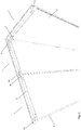
- Figure 1 shows a panel (1) according to the invention, with the front outer plate (2) removed.
- the intermediate structure (5) is visible here, which extends over a large part of the height or length of the outer plate (2), but does not extend completely to the top.
- a rigid reinforcing element (3) is provided at the top, typically wood, although other materials are also possible.
- This reinforcing element extends over most of the width of the panel, and is provided with coupling elements (4a, 4b) at the lateral ends.
- the lateral ends are oriented to hook together (first on second) at adjacent panels with the hook-shaped ends (8) of the coupling elements. This coupling is more clearly visible in Figure 2 .
- the intermediate structure is approximately the same width as the outer plates, but offset so that they protrude laterally relative to the outer plates on one side of the panel and indent approximately the same distance on the other side. This allows the panels to be joined, with the protruding intermediate structure sliding into the recess of an adjacent panel.
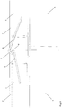
- Figure 3 shows a panel adapted to allow corner joints, in this case a right angle, although other versions are possible. This is done by means of a specific corner reinforcement (6) which is mounted on the outer plate and the reinforcing element, and allows another (ordinary) panel to be hooked into with the coupling element (4a). In addition, corner connecting elements (7) are provided on the corner panel to prevent damage.
- Figure 10 shows a modified version of the corner reinforcement (6) with an anchoring and downwards hooking end piece (18) suitable for anchoring to a coupling element (4b).
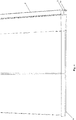
- Figure 4 shows a bottom side of panels according to the invention, in which the bottom reinforcing elements (9) protrude at the bottom with respect to the outer plates. This ensures that the stronger reinforcing elements are used for support, and can also be useful when connecting to bases.
- Figure 5 shows a detail of the top side of a panel, in which it is visible that at the level of the reinforcing elements (9) a second reinforcing layer (10) is provided on the outer plate (2), typically of the same material, this to reinforce this zone, which has to handle more forces.
- the thicknesses D1 and D2 are preferably equal and are preferably between 1.0 mm and 5.0 mm, more preferably between 2.0 mm and 3.0 mm and most preferably about 2.5 mm.
- the width B1 is preferably between 20 and 40 mm, more preferably about 30 mm; B2 preferably between 30 and 40 mm, and more preferably about 35 mm.
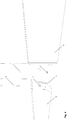
- Figure 6 shows a detail of the underside of a panel and a base (1), the base comprising two slats (12) interconnected by a number of spacer elements (13), which are themselves provided with a base (15), preferably that can be slid out / is detachable by unscrewing.
- the slats are provided on the top with a stepped recess (14) which allows to receive a panel in the first zone, and is dimensioned in the deeper zone to receive only the protruding portion of the second reinforcing element (9).
- Figure 7 shows the possibility of a stacking of panels in the height direction, in which a lower reinforcing element (9) can be received in a recess at the top of a lower panel (1).
- the lower reinforcing element (9) protrudes from the outer plates (2) as far as the outer plates (2) extend from the upper reinforcing element (3).
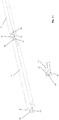
- FIGs 8 and 9 show the positioning elements (16, 17) provided on the lower fastening elements (9) for aligning adjacent panels.
- Figure 11 shows a detail drawing of an embodiment of the reinforcing elements (3) with adapted coupling elements (4a, 4b), the coupling elements in this case comprising two fingers (19) with a recess (20) between them, the recess suitable for allowing passage of cables and the like.
Landscapes
- Engineering & Computer Science (AREA)
- Architecture (AREA)
- Physics & Mathematics (AREA)
- Electromagnetism (AREA)
- Civil Engineering (AREA)
- Structural Engineering (AREA)
- Finishing Walls (AREA)
- Display Racks (AREA)
Applications Claiming Priority (1)
| Application Number | Priority Date | Filing Date | Title |
|---|---|---|---|
| BE20205352A BE1028327B1 (nl) | 2020-05-20 | 2020-05-20 | Modulaire paneelwanden voor beursstandbouw |
Publications (3)
| Publication Number | Publication Date |
|---|---|
| EP3936675A1 true EP3936675A1 (de) | 2022-01-12 |
| EP3936675B1 EP3936675B1 (de) | 2024-01-31 |
| EP3936675C0 EP3936675C0 (de) | 2024-01-31 |
Family
ID=70968678
Family Applications (1)
| Application Number | Title | Priority Date | Filing Date |
|---|---|---|---|
| EP21175065.8A Active EP3936675B1 (de) | 2020-05-20 | 2021-05-20 | Anordnung von modularen panelwänden für messestandbau |
Country Status (2)
| Country | Link |
|---|---|
| EP (1) | EP3936675B1 (de) |
| BE (1) | BE1028327B1 (de) |
Cited By (1)
| Publication number | Priority date | Publication date | Assignee | Title |
|---|---|---|---|---|
| CN116145884A (zh) * | 2023-01-04 | 2023-05-23 | 安徽省润乾节能建材科技股份有限公司 | 一种便于拼接的蒸压加气块及其生产工艺 |
Citations (4)
| Publication number | Priority date | Publication date | Assignee | Title |
|---|---|---|---|---|
| KR100810650B1 (ko) | 2007-02-16 | 2008-03-06 | 르호봇홀딩스주식회사 | 건축용 패널 및 패널 조립 구조 |
| US20140208673A1 (en) | 2013-01-29 | 2014-07-31 | Cityneon Displays (Taiwan) Co., Ltd. | Partition structure having engaging assembly |
| US20170121961A1 (en) | 2015-11-04 | 2017-05-04 | Earth Technologies Usa Limited | Systems, methods, apparatus, and compositions for building materials and construction |
| US20180347173A1 (en) | 2015-11-20 | 2018-12-06 | Alejandro GAJARDO SILVA | Elasto-mechanical chamber |
-
2020
- 2020-05-20 BE BE20205352A patent/BE1028327B1/nl active IP Right Grant
-
2021
- 2021-05-20 EP EP21175065.8A patent/EP3936675B1/de active Active
Patent Citations (4)
| Publication number | Priority date | Publication date | Assignee | Title |
|---|---|---|---|---|
| KR100810650B1 (ko) | 2007-02-16 | 2008-03-06 | 르호봇홀딩스주식회사 | 건축용 패널 및 패널 조립 구조 |
| US20140208673A1 (en) | 2013-01-29 | 2014-07-31 | Cityneon Displays (Taiwan) Co., Ltd. | Partition structure having engaging assembly |
| US20170121961A1 (en) | 2015-11-04 | 2017-05-04 | Earth Technologies Usa Limited | Systems, methods, apparatus, and compositions for building materials and construction |
| US20180347173A1 (en) | 2015-11-20 | 2018-12-06 | Alejandro GAJARDO SILVA | Elasto-mechanical chamber |
Cited By (1)
| Publication number | Priority date | Publication date | Assignee | Title |
|---|---|---|---|---|
| CN116145884A (zh) * | 2023-01-04 | 2023-05-23 | 安徽省润乾节能建材科技股份有限公司 | 一种便于拼接的蒸压加气块及其生产工艺 |
Also Published As
| Publication number | Publication date |
|---|---|
| EP3936675B1 (de) | 2024-01-31 |
| EP3936675C0 (de) | 2024-01-31 |
| BE1028327A1 (nl) | 2021-12-16 |
| BE1028327B1 (nl) | 2021-12-21 |
Similar Documents
| Publication | Publication Date | Title |
|---|---|---|
| WO1995023899A1 (en) | Connecting member for concrete form | |
| US7445192B2 (en) | Shear wall template | |
| EP2304134B1 (de) | Tragbare verriegelungshilfe und plattformsystem | |
| US6494639B1 (en) | Primary connector for pre-cast structures | |
| US4979554A (en) | Flexible display panel | |
| ITPD20000278A1 (it) | Elementi modulari per la realizzazione di casseforme | |
| US20180334814A1 (en) | Lightweight roofing support system and method of making and using | |
| EP2468972A2 (de) | Trennwand mit einer Vorder- und Rückwand, die an einem Rahmen mittels Klettverschlüssen befestigt ist | |
| HK1047608B (zh) | 立方形型材单元及其型材钢片 | |
| WO2015070342A1 (en) | Extruded deck board with finishing material insert | |
| EP3936675B1 (de) | Anordnung von modularen panelwänden für messestandbau | |
| HU220325B (hu) | Árokmegtámasztó szerkezet | |
| US20220259873A1 (en) | Insulating concrete form apparatus | |
| WO2019077326A1 (en) | IMPROVEMENTS IN OR RELATING TO A SAFETY FLOOR | |
| US20090107078A1 (en) | Modular building system and methods thereof | |
| US20240110389A1 (en) | Interlockable modular floor tile and method of assembling same | |
| US8266845B2 (en) | Device for producing above ground open or closed structures | |
| US9856653B1 (en) | Modular precast concrete steps | |
| US20020134037A1 (en) | Attachment system and method for attaching wall or floor systems to respective floors or walls | |
| ES2230754T3 (es) | Plataforma de andamio. | |
| ES2333305T3 (es) | Sistema de componentes estructurales para estrados/plataformas y/o tribunas y/o tarimas. | |
| CN201874187U (zh) | 一种长板材固定装置及其固定的长板材 | |
| AU2004202341B2 (en) | Modular Platform Assembly & System | |
| US7472779B2 (en) | Chute transition frame and chute system incorporating the same | |
| GB2430461A (en) | Safety Platform Assembly |
Legal Events
| Date | Code | Title | Description |
|---|---|---|---|
| PUAI | Public reference made under article 153(3) epc to a published international application that has entered the european phase |
Free format text: ORIGINAL CODE: 0009012 |
|
| STAA | Information on the status of an ep patent application or granted ep patent |
Free format text: STATUS: THE APPLICATION HAS BEEN PUBLISHED |
|
| AK | Designated contracting states |
Kind code of ref document: A1 Designated state(s): AL AT BE BG CH CY CZ DE DK EE ES FI FR GB GR HR HU IE IS IT LI LT LU LV MC MK MT NL NO PL PT RO RS SE SI SK SM TR |
|
| B565 | Issuance of search results under rule 164(2) epc |
Effective date: 20211215 |
|
| STAA | Information on the status of an ep patent application or granted ep patent |
Free format text: STATUS: REQUEST FOR EXAMINATION WAS MADE |
|
| 17P | Request for examination filed |
Effective date: 20220527 |
|
| RBV | Designated contracting states (corrected) |
Designated state(s): AL AT BE BG CH CY CZ DE DK EE ES FI FR GB GR HR HU IE IS IT LI LT LU LV MC MK MT NL NO PL PT RO RS SE SI SK SM TR |
|
| GRAP | Despatch of communication of intention to grant a patent |
Free format text: ORIGINAL CODE: EPIDOSNIGR1 |
|
| STAA | Information on the status of an ep patent application or granted ep patent |
Free format text: STATUS: GRANT OF PATENT IS INTENDED |
|
| RIC1 | Information provided on ipc code assigned before grant |
Ipc: E04B 2/74 20060101ALI20230301BHEP Ipc: E04B 1/61 20060101AFI20230301BHEP |
|
| INTG | Intention to grant announced |
Effective date: 20230316 |
|
| GRAJ | Information related to disapproval of communication of intention to grant by the applicant or resumption of examination proceedings by the epo deleted |
Free format text: ORIGINAL CODE: EPIDOSDIGR1 |
|
| STAA | Information on the status of an ep patent application or granted ep patent |
Free format text: STATUS: REQUEST FOR EXAMINATION WAS MADE |
|
| INTC | Intention to grant announced (deleted) | ||
| GRAP | Despatch of communication of intention to grant a patent |
Free format text: ORIGINAL CODE: EPIDOSNIGR1 |
|
| STAA | Information on the status of an ep patent application or granted ep patent |
Free format text: STATUS: GRANT OF PATENT IS INTENDED |
|
| INTG | Intention to grant announced |
Effective date: 20230822 |
|
| INTG | Intention to grant announced |
Effective date: 20230901 |
|
| GRAS | Grant fee paid |
Free format text: ORIGINAL CODE: EPIDOSNIGR3 |
|
| GRAA | (expected) grant |
Free format text: ORIGINAL CODE: 0009210 |
|
| STAA | Information on the status of an ep patent application or granted ep patent |
Free format text: STATUS: THE PATENT HAS BEEN GRANTED |
|
| AK | Designated contracting states |
Kind code of ref document: B1 Designated state(s): AL AT BE BG CH CY CZ DE DK EE ES FI FR GB GR HR HU IE IS IT LI LT LU LV MC MK MT NL NO PL PT RO RS SE SI SK SM TR |
|
| REG | Reference to a national code |
Ref country code: GB Ref legal event code: FG4D Ref country code: CH Ref legal event code: EP |
|
| REG | Reference to a national code |
Ref country code: DE Ref legal event code: R096 Ref document number: 602021008865 Country of ref document: DE |
|
| REG | Reference to a national code |
Ref country code: IE Ref legal event code: FG4D |
|
| U01 | Request for unitary effect filed |
Effective date: 20240229 |
|
| U07 | Unitary effect registered |
Designated state(s): AT BE BG DE DK EE FI FR IT LT LU LV MT NL PT SE SI Effective date: 20240307 |
|
| PG25 | Lapsed in a contracting state [announced via postgrant information from national office to epo] |
Ref country code: IS Free format text: LAPSE BECAUSE OF FAILURE TO SUBMIT A TRANSLATION OF THE DESCRIPTION OR TO PAY THE FEE WITHIN THE PRESCRIBED TIME-LIMIT Effective date: 20240531 |
|
| U20 | Renewal fee for the european patent with unitary effect paid |
Year of fee payment: 4 Effective date: 20240603 |
|
| PG25 | Lapsed in a contracting state [announced via postgrant information from national office to epo] |
Ref country code: GR Free format text: LAPSE BECAUSE OF FAILURE TO SUBMIT A TRANSLATION OF THE DESCRIPTION OR TO PAY THE FEE WITHIN THE PRESCRIBED TIME-LIMIT Effective date: 20240501 |
|
| PG25 | Lapsed in a contracting state [announced via postgrant information from national office to epo] |
Ref country code: HR Free format text: LAPSE BECAUSE OF FAILURE TO SUBMIT A TRANSLATION OF THE DESCRIPTION OR TO PAY THE FEE WITHIN THE PRESCRIBED TIME-LIMIT Effective date: 20240131 Ref country code: RS Free format text: LAPSE BECAUSE OF FAILURE TO SUBMIT A TRANSLATION OF THE DESCRIPTION OR TO PAY THE FEE WITHIN THE PRESCRIBED TIME-LIMIT Effective date: 20240430 |
|
| PG25 | Lapsed in a contracting state [announced via postgrant information from national office to epo] |
Ref country code: ES Free format text: LAPSE BECAUSE OF FAILURE TO SUBMIT A TRANSLATION OF THE DESCRIPTION OR TO PAY THE FEE WITHIN THE PRESCRIBED TIME-LIMIT Effective date: 20240131 |
|
| PG25 | Lapsed in a contracting state [announced via postgrant information from national office to epo] |
Ref country code: RS Free format text: LAPSE BECAUSE OF FAILURE TO SUBMIT A TRANSLATION OF THE DESCRIPTION OR TO PAY THE FEE WITHIN THE PRESCRIBED TIME-LIMIT Effective date: 20240430 Ref country code: NO Free format text: LAPSE BECAUSE OF FAILURE TO SUBMIT A TRANSLATION OF THE DESCRIPTION OR TO PAY THE FEE WITHIN THE PRESCRIBED TIME-LIMIT Effective date: 20240430 Ref country code: IS Free format text: LAPSE BECAUSE OF FAILURE TO SUBMIT A TRANSLATION OF THE DESCRIPTION OR TO PAY THE FEE WITHIN THE PRESCRIBED TIME-LIMIT Effective date: 20240531 Ref country code: HR Free format text: LAPSE BECAUSE OF FAILURE TO SUBMIT A TRANSLATION OF THE DESCRIPTION OR TO PAY THE FEE WITHIN THE PRESCRIBED TIME-LIMIT Effective date: 20240131 Ref country code: GR Free format text: LAPSE BECAUSE OF FAILURE TO SUBMIT A TRANSLATION OF THE DESCRIPTION OR TO PAY THE FEE WITHIN THE PRESCRIBED TIME-LIMIT Effective date: 20240501 Ref country code: ES Free format text: LAPSE BECAUSE OF FAILURE TO SUBMIT A TRANSLATION OF THE DESCRIPTION OR TO PAY THE FEE WITHIN THE PRESCRIBED TIME-LIMIT Effective date: 20240131 |
|
| PG25 | Lapsed in a contracting state [announced via postgrant information from national office to epo] |
Ref country code: PL Free format text: LAPSE BECAUSE OF FAILURE TO SUBMIT A TRANSLATION OF THE DESCRIPTION OR TO PAY THE FEE WITHIN THE PRESCRIBED TIME-LIMIT Effective date: 20240131 |
|
| PG25 | Lapsed in a contracting state [announced via postgrant information from national office to epo] |
Ref country code: PL Free format text: LAPSE BECAUSE OF FAILURE TO SUBMIT A TRANSLATION OF THE DESCRIPTION OR TO PAY THE FEE WITHIN THE PRESCRIBED TIME-LIMIT Effective date: 20240131 |
|
| PG25 | Lapsed in a contracting state [announced via postgrant information from national office to epo] |
Ref country code: SM Free format text: LAPSE BECAUSE OF FAILURE TO SUBMIT A TRANSLATION OF THE DESCRIPTION OR TO PAY THE FEE WITHIN THE PRESCRIBED TIME-LIMIT Effective date: 20240131 |
|
| PG25 | Lapsed in a contracting state [announced via postgrant information from national office to epo] |
Ref country code: CZ Free format text: LAPSE BECAUSE OF FAILURE TO SUBMIT A TRANSLATION OF THE DESCRIPTION OR TO PAY THE FEE WITHIN THE PRESCRIBED TIME-LIMIT Effective date: 20240131 |
|
| PG25 | Lapsed in a contracting state [announced via postgrant information from national office to epo] |
Ref country code: SK Free format text: LAPSE BECAUSE OF FAILURE TO SUBMIT A TRANSLATION OF THE DESCRIPTION OR TO PAY THE FEE WITHIN THE PRESCRIBED TIME-LIMIT Effective date: 20240131 |
|
| PG25 | Lapsed in a contracting state [announced via postgrant information from national office to epo] |
Ref country code: SM Free format text: LAPSE BECAUSE OF FAILURE TO SUBMIT A TRANSLATION OF THE DESCRIPTION OR TO PAY THE FEE WITHIN THE PRESCRIBED TIME-LIMIT Effective date: 20240131 Ref country code: SK Free format text: LAPSE BECAUSE OF FAILURE TO SUBMIT A TRANSLATION OF THE DESCRIPTION OR TO PAY THE FEE WITHIN THE PRESCRIBED TIME-LIMIT Effective date: 20240131 Ref country code: RO Free format text: LAPSE BECAUSE OF FAILURE TO SUBMIT A TRANSLATION OF THE DESCRIPTION OR TO PAY THE FEE WITHIN THE PRESCRIBED TIME-LIMIT Effective date: 20240131 Ref country code: CZ Free format text: LAPSE BECAUSE OF FAILURE TO SUBMIT A TRANSLATION OF THE DESCRIPTION OR TO PAY THE FEE WITHIN THE PRESCRIBED TIME-LIMIT Effective date: 20240131 |
|
| REG | Reference to a national code |
Ref country code: DE Ref legal event code: R097 Ref document number: 602021008865 Country of ref document: DE |
|
| PLBE | No opposition filed within time limit |
Free format text: ORIGINAL CODE: 0009261 |
|
| STAA | Information on the status of an ep patent application or granted ep patent |
Free format text: STATUS: NO OPPOSITION FILED WITHIN TIME LIMIT |
|
| REG | Reference to a national code |
Ref country code: CH Ref legal event code: PL |
|
| 26N | No opposition filed |
Effective date: 20241101 |
|
| PG25 | Lapsed in a contracting state [announced via postgrant information from national office to epo] |
Ref country code: MC Free format text: LAPSE BECAUSE OF FAILURE TO SUBMIT A TRANSLATION OF THE DESCRIPTION OR TO PAY THE FEE WITHIN THE PRESCRIBED TIME-LIMIT Effective date: 20240131 |
|
| PG25 | Lapsed in a contracting state [announced via postgrant information from national office to epo] |
Ref country code: MC Free format text: LAPSE BECAUSE OF FAILURE TO SUBMIT A TRANSLATION OF THE DESCRIPTION OR TO PAY THE FEE WITHIN THE PRESCRIBED TIME-LIMIT Effective date: 20240131 Ref country code: CH Free format text: LAPSE BECAUSE OF NON-PAYMENT OF DUE FEES Effective date: 20240531 |
|
| PG25 | Lapsed in a contracting state [announced via postgrant information from national office to epo] |
Ref country code: IE Free format text: LAPSE BECAUSE OF NON-PAYMENT OF DUE FEES Effective date: 20240520 |
|
| U20 | Renewal fee for the european patent with unitary effect paid |
Year of fee payment: 5 Effective date: 20250528 |
|
| PGFP | Annual fee paid to national office [announced via postgrant information from national office to epo] |
Ref country code: GB Payment date: 20250527 Year of fee payment: 5 |
|
| PG25 | Lapsed in a contracting state [announced via postgrant information from national office to epo] |
Ref country code: CY Free format text: LAPSE BECAUSE OF FAILURE TO SUBMIT A TRANSLATION OF THE DESCRIPTION OR TO PAY THE FEE WITHIN THE PRESCRIBED TIME-LIMIT; INVALID AB INITIO Effective date: 20210520 |
|
| PG25 | Lapsed in a contracting state [announced via postgrant information from national office to epo] |
Ref country code: HU Free format text: LAPSE BECAUSE OF FAILURE TO SUBMIT A TRANSLATION OF THE DESCRIPTION OR TO PAY THE FEE WITHIN THE PRESCRIBED TIME-LIMIT; INVALID AB INITIO Effective date: 20210520 |