EP3936402A2 - Electronic control unit for a hybrid vehicle - Google Patents
Electronic control unit for a hybrid vehicle Download PDFInfo
- Publication number
- EP3936402A2 EP3936402A2 EP21193923.6A EP21193923A EP3936402A2 EP 3936402 A2 EP3936402 A2 EP 3936402A2 EP 21193923 A EP21193923 A EP 21193923A EP 3936402 A2 EP3936402 A2 EP 3936402A2
- Authority
- EP
- European Patent Office
- Prior art keywords
- charging
- opportunities
- vehicle
- battery
- control unit
- Prior art date
- Legal status (The legal status is an assumption and is not a legal conclusion. Google has not performed a legal analysis and makes no representation as to the accuracy of the status listed.)
- Pending
Links
Images

Classifications
-
- B—PERFORMING OPERATIONS; TRANSPORTING
- B60—VEHICLES IN GENERAL
- B60L—PROPULSION OF ELECTRICALLY-PROPELLED VEHICLES; SUPPLYING ELECTRIC POWER FOR AUXILIARY EQUIPMENT OF ELECTRICALLY-PROPELLED VEHICLES; ELECTRODYNAMIC BRAKE SYSTEMS FOR VEHICLES IN GENERAL; MAGNETIC SUSPENSION OR LEVITATION FOR VEHICLES; MONITORING OPERATING VARIABLES OF ELECTRICALLY-PROPELLED VEHICLES; ELECTRIC SAFETY DEVICES FOR ELECTRICALLY-PROPELLED VEHICLES
- B60L53/00—Methods of charging batteries, specially adapted for electric vehicles; Charging stations or on-board charging equipment therefor; Exchange of energy storage elements in electric vehicles
-
- B—PERFORMING OPERATIONS; TRANSPORTING
- B60—VEHICLES IN GENERAL
- B60K—ARRANGEMENT OR MOUNTING OF PROPULSION UNITS OR OF TRANSMISSIONS IN VEHICLES; ARRANGEMENT OR MOUNTING OF PLURAL DIVERSE PRIME-MOVERS IN VEHICLES; AUXILIARY DRIVES FOR VEHICLES; INSTRUMENTATION OR DASHBOARDS FOR VEHICLES; ARRANGEMENTS IN CONNECTION WITH COOLING, AIR INTAKE, GAS EXHAUST OR FUEL SUPPLY OF PROPULSION UNITS IN VEHICLES
- B60K15/00—Arrangement in connection with fuel supply of combustion engines or other fuel consuming energy converters, e.g. fuel cells; Mounting or construction of fuel tanks
- B60K15/03—Fuel tanks
-
- B—PERFORMING OPERATIONS; TRANSPORTING
- B60—VEHICLES IN GENERAL
- B60K—ARRANGEMENT OR MOUNTING OF PROPULSION UNITS OR OF TRANSMISSIONS IN VEHICLES; ARRANGEMENT OR MOUNTING OF PLURAL DIVERSE PRIME-MOVERS IN VEHICLES; AUXILIARY DRIVES FOR VEHICLES; INSTRUMENTATION OR DASHBOARDS FOR VEHICLES; ARRANGEMENTS IN CONNECTION WITH COOLING, AIR INTAKE, GAS EXHAUST OR FUEL SUPPLY OF PROPULSION UNITS IN VEHICLES
- B60K6/00—Arrangement or mounting of plural diverse prime-movers for mutual or common propulsion, e.g. hybrid propulsion systems comprising electric motors and internal combustion engines ; Control systems therefor, i.e. systems controlling two or more prime movers, or controlling one of these prime movers and any of the transmission, drive or drive units Informative references: mechanical gearings with secondary electric drive F16H3/72; arrangements for handling mechanical energy structurally associated with the dynamo-electric machine H02K7/00; machines comprising structurally interrelated motor and generator parts H02K51/00; dynamo-electric machines not otherwise provided for in H02K see H02K99/00
- B60K6/20—Arrangement or mounting of plural diverse prime-movers for mutual or common propulsion, e.g. hybrid propulsion systems comprising electric motors and internal combustion engines ; Control systems therefor, i.e. systems controlling two or more prime movers, or controlling one of these prime movers and any of the transmission, drive or drive units Informative references: mechanical gearings with secondary electric drive F16H3/72; arrangements for handling mechanical energy structurally associated with the dynamo-electric machine H02K7/00; machines comprising structurally interrelated motor and generator parts H02K51/00; dynamo-electric machines not otherwise provided for in H02K see H02K99/00 the prime-movers consisting of electric motors and internal combustion engines, e.g. HEVs
- B60K6/22—Arrangement or mounting of plural diverse prime-movers for mutual or common propulsion, e.g. hybrid propulsion systems comprising electric motors and internal combustion engines ; Control systems therefor, i.e. systems controlling two or more prime movers, or controlling one of these prime movers and any of the transmission, drive or drive units Informative references: mechanical gearings with secondary electric drive F16H3/72; arrangements for handling mechanical energy structurally associated with the dynamo-electric machine H02K7/00; machines comprising structurally interrelated motor and generator parts H02K51/00; dynamo-electric machines not otherwise provided for in H02K see H02K99/00 the prime-movers consisting of electric motors and internal combustion engines, e.g. HEVs characterised by apparatus, components or means specially adapted for HEVs
- B60K6/28—Arrangement or mounting of plural diverse prime-movers for mutual or common propulsion, e.g. hybrid propulsion systems comprising electric motors and internal combustion engines ; Control systems therefor, i.e. systems controlling two or more prime movers, or controlling one of these prime movers and any of the transmission, drive or drive units Informative references: mechanical gearings with secondary electric drive F16H3/72; arrangements for handling mechanical energy structurally associated with the dynamo-electric machine H02K7/00; machines comprising structurally interrelated motor and generator parts H02K51/00; dynamo-electric machines not otherwise provided for in H02K see H02K99/00 the prime-movers consisting of electric motors and internal combustion engines, e.g. HEVs characterised by apparatus, components or means specially adapted for HEVs characterised by the electric energy storing means, e.g. batteries or capacitors
-
- B—PERFORMING OPERATIONS; TRANSPORTING
- B60—VEHICLES IN GENERAL
- B60K—ARRANGEMENT OR MOUNTING OF PROPULSION UNITS OR OF TRANSMISSIONS IN VEHICLES; ARRANGEMENT OR MOUNTING OF PLURAL DIVERSE PRIME-MOVERS IN VEHICLES; AUXILIARY DRIVES FOR VEHICLES; INSTRUMENTATION OR DASHBOARDS FOR VEHICLES; ARRANGEMENTS IN CONNECTION WITH COOLING, AIR INTAKE, GAS EXHAUST OR FUEL SUPPLY OF PROPULSION UNITS IN VEHICLES
- B60K6/00—Arrangement or mounting of plural diverse prime-movers for mutual or common propulsion, e.g. hybrid propulsion systems comprising electric motors and internal combustion engines ; Control systems therefor, i.e. systems controlling two or more prime movers, or controlling one of these prime movers and any of the transmission, drive or drive units Informative references: mechanical gearings with secondary electric drive F16H3/72; arrangements for handling mechanical energy structurally associated with the dynamo-electric machine H02K7/00; machines comprising structurally interrelated motor and generator parts H02K51/00; dynamo-electric machines not otherwise provided for in H02K see H02K99/00
- B60K6/20—Arrangement or mounting of plural diverse prime-movers for mutual or common propulsion, e.g. hybrid propulsion systems comprising electric motors and internal combustion engines ; Control systems therefor, i.e. systems controlling two or more prime movers, or controlling one of these prime movers and any of the transmission, drive or drive units Informative references: mechanical gearings with secondary electric drive F16H3/72; arrangements for handling mechanical energy structurally associated with the dynamo-electric machine H02K7/00; machines comprising structurally interrelated motor and generator parts H02K51/00; dynamo-electric machines not otherwise provided for in H02K see H02K99/00 the prime-movers consisting of electric motors and internal combustion engines, e.g. HEVs
- B60K6/42—Arrangement or mounting of plural diverse prime-movers for mutual or common propulsion, e.g. hybrid propulsion systems comprising electric motors and internal combustion engines ; Control systems therefor, i.e. systems controlling two or more prime movers, or controlling one of these prime movers and any of the transmission, drive or drive units Informative references: mechanical gearings with secondary electric drive F16H3/72; arrangements for handling mechanical energy structurally associated with the dynamo-electric machine H02K7/00; machines comprising structurally interrelated motor and generator parts H02K51/00; dynamo-electric machines not otherwise provided for in H02K see H02K99/00 the prime-movers consisting of electric motors and internal combustion engines, e.g. HEVs characterised by the architecture of the hybrid electric vehicle
- B60K6/46—Series type
-
- B—PERFORMING OPERATIONS; TRANSPORTING
- B60—VEHICLES IN GENERAL
- B60L—PROPULSION OF ELECTRICALLY-PROPELLED VEHICLES; SUPPLYING ELECTRIC POWER FOR AUXILIARY EQUIPMENT OF ELECTRICALLY-PROPELLED VEHICLES; ELECTRODYNAMIC BRAKE SYSTEMS FOR VEHICLES IN GENERAL; MAGNETIC SUSPENSION OR LEVITATION FOR VEHICLES; MONITORING OPERATING VARIABLES OF ELECTRICALLY-PROPELLED VEHICLES; ELECTRIC SAFETY DEVICES FOR ELECTRICALLY-PROPELLED VEHICLES
- B60L50/00—Electric propulsion with power supplied within the vehicle
- B60L50/10—Electric propulsion with power supplied within the vehicle using propulsion power supplied by engine-driven generators, e.g. generators driven by combustion engines
- B60L50/15—Electric propulsion with power supplied within the vehicle using propulsion power supplied by engine-driven generators, e.g. generators driven by combustion engines with additional electric power supply
-
- B—PERFORMING OPERATIONS; TRANSPORTING
- B60—VEHICLES IN GENERAL
- B60L—PROPULSION OF ELECTRICALLY-PROPELLED VEHICLES; SUPPLYING ELECTRIC POWER FOR AUXILIARY EQUIPMENT OF ELECTRICALLY-PROPELLED VEHICLES; ELECTRODYNAMIC BRAKE SYSTEMS FOR VEHICLES IN GENERAL; MAGNETIC SUSPENSION OR LEVITATION FOR VEHICLES; MONITORING OPERATING VARIABLES OF ELECTRICALLY-PROPELLED VEHICLES; ELECTRIC SAFETY DEVICES FOR ELECTRICALLY-PROPELLED VEHICLES
- B60L53/00—Methods of charging batteries, specially adapted for electric vehicles; Charging stations or on-board charging equipment therefor; Exchange of energy storage elements in electric vehicles
- B60L53/10—Methods of charging batteries, specially adapted for electric vehicles; Charging stations or on-board charging equipment therefor; Exchange of energy storage elements in electric vehicles characterised by the energy transfer between the charging station and the vehicle
- B60L53/14—Conductive energy transfer
- B60L53/16—Connectors, e.g. plugs or sockets, specially adapted for charging electric vehicles
-
- B—PERFORMING OPERATIONS; TRANSPORTING
- B60—VEHICLES IN GENERAL
- B60L—PROPULSION OF ELECTRICALLY-PROPELLED VEHICLES; SUPPLYING ELECTRIC POWER FOR AUXILIARY EQUIPMENT OF ELECTRICALLY-PROPELLED VEHICLES; ELECTRODYNAMIC BRAKE SYSTEMS FOR VEHICLES IN GENERAL; MAGNETIC SUSPENSION OR LEVITATION FOR VEHICLES; MONITORING OPERATING VARIABLES OF ELECTRICALLY-PROPELLED VEHICLES; ELECTRIC SAFETY DEVICES FOR ELECTRICALLY-PROPELLED VEHICLES
- B60L53/00—Methods of charging batteries, specially adapted for electric vehicles; Charging stations or on-board charging equipment therefor; Exchange of energy storage elements in electric vehicles
- B60L53/50—Charging stations characterised by energy-storage or power-generation means
-
- B—PERFORMING OPERATIONS; TRANSPORTING
- B60—VEHICLES IN GENERAL
- B60L—PROPULSION OF ELECTRICALLY-PROPELLED VEHICLES; SUPPLYING ELECTRIC POWER FOR AUXILIARY EQUIPMENT OF ELECTRICALLY-PROPELLED VEHICLES; ELECTRODYNAMIC BRAKE SYSTEMS FOR VEHICLES IN GENERAL; MAGNETIC SUSPENSION OR LEVITATION FOR VEHICLES; MONITORING OPERATING VARIABLES OF ELECTRICALLY-PROPELLED VEHICLES; ELECTRIC SAFETY DEVICES FOR ELECTRICALLY-PROPELLED VEHICLES
- B60L58/00—Methods or circuit arrangements for monitoring or controlling batteries or fuel cells, specially adapted for electric vehicles
- B60L58/10—Methods or circuit arrangements for monitoring or controlling batteries or fuel cells, specially adapted for electric vehicles for monitoring or controlling batteries
-
- B—PERFORMING OPERATIONS; TRANSPORTING
- B60—VEHICLES IN GENERAL
- B60W—CONJOINT CONTROL OF VEHICLE SUB-UNITS OF DIFFERENT TYPE OR DIFFERENT FUNCTION; CONTROL SYSTEMS SPECIALLY ADAPTED FOR HYBRID VEHICLES; ROAD VEHICLE DRIVE CONTROL SYSTEMS FOR PURPOSES NOT RELATED TO THE CONTROL OF A PARTICULAR SUB-UNIT
- B60W40/00—Estimation or calculation of non-directly measurable driving parameters for road vehicle drive control systems not related to the control of a particular sub unit, e.g. by using mathematical models
- B60W40/08—Estimation or calculation of non-directly measurable driving parameters for road vehicle drive control systems not related to the control of a particular sub unit, e.g. by using mathematical models related to drivers or passengers
- B60W40/09—Driving style or behaviour
-
- B—PERFORMING OPERATIONS; TRANSPORTING
- B60—VEHICLES IN GENERAL
- B60K—ARRANGEMENT OR MOUNTING OF PROPULSION UNITS OR OF TRANSMISSIONS IN VEHICLES; ARRANGEMENT OR MOUNTING OF PLURAL DIVERSE PRIME-MOVERS IN VEHICLES; AUXILIARY DRIVES FOR VEHICLES; INSTRUMENTATION OR DASHBOARDS FOR VEHICLES; ARRANGEMENTS IN CONNECTION WITH COOLING, AIR INTAKE, GAS EXHAUST OR FUEL SUPPLY OF PROPULSION UNITS IN VEHICLES
- B60K6/00—Arrangement or mounting of plural diverse prime-movers for mutual or common propulsion, e.g. hybrid propulsion systems comprising electric motors and internal combustion engines ; Control systems therefor, i.e. systems controlling two or more prime movers, or controlling one of these prime movers and any of the transmission, drive or drive units Informative references: mechanical gearings with secondary electric drive F16H3/72; arrangements for handling mechanical energy structurally associated with the dynamo-electric machine H02K7/00; machines comprising structurally interrelated motor and generator parts H02K51/00; dynamo-electric machines not otherwise provided for in H02K see H02K99/00
- B60K6/20—Arrangement or mounting of plural diverse prime-movers for mutual or common propulsion, e.g. hybrid propulsion systems comprising electric motors and internal combustion engines ; Control systems therefor, i.e. systems controlling two or more prime movers, or controlling one of these prime movers and any of the transmission, drive or drive units Informative references: mechanical gearings with secondary electric drive F16H3/72; arrangements for handling mechanical energy structurally associated with the dynamo-electric machine H02K7/00; machines comprising structurally interrelated motor and generator parts H02K51/00; dynamo-electric machines not otherwise provided for in H02K see H02K99/00 the prime-movers consisting of electric motors and internal combustion engines, e.g. HEVs
- B60K6/42—Arrangement or mounting of plural diverse prime-movers for mutual or common propulsion, e.g. hybrid propulsion systems comprising electric motors and internal combustion engines ; Control systems therefor, i.e. systems controlling two or more prime movers, or controlling one of these prime movers and any of the transmission, drive or drive units Informative references: mechanical gearings with secondary electric drive F16H3/72; arrangements for handling mechanical energy structurally associated with the dynamo-electric machine H02K7/00; machines comprising structurally interrelated motor and generator parts H02K51/00; dynamo-electric machines not otherwise provided for in H02K see H02K99/00 the prime-movers consisting of electric motors and internal combustion engines, e.g. HEVs characterised by the architecture of the hybrid electric vehicle
- B60K6/48—Parallel type
- B60K2006/4825—Electric machine connected or connectable to gearbox input shaft
-
- B—PERFORMING OPERATIONS; TRANSPORTING
- B60—VEHICLES IN GENERAL
- B60K—ARRANGEMENT OR MOUNTING OF PROPULSION UNITS OR OF TRANSMISSIONS IN VEHICLES; ARRANGEMENT OR MOUNTING OF PLURAL DIVERSE PRIME-MOVERS IN VEHICLES; AUXILIARY DRIVES FOR VEHICLES; INSTRUMENTATION OR DASHBOARDS FOR VEHICLES; ARRANGEMENTS IN CONNECTION WITH COOLING, AIR INTAKE, GAS EXHAUST OR FUEL SUPPLY OF PROPULSION UNITS IN VEHICLES
- B60K6/00—Arrangement or mounting of plural diverse prime-movers for mutual or common propulsion, e.g. hybrid propulsion systems comprising electric motors and internal combustion engines ; Control systems therefor, i.e. systems controlling two or more prime movers, or controlling one of these prime movers and any of the transmission, drive or drive units Informative references: mechanical gearings with secondary electric drive F16H3/72; arrangements for handling mechanical energy structurally associated with the dynamo-electric machine H02K7/00; machines comprising structurally interrelated motor and generator parts H02K51/00; dynamo-electric machines not otherwise provided for in H02K see H02K99/00
- B60K6/20—Arrangement or mounting of plural diverse prime-movers for mutual or common propulsion, e.g. hybrid propulsion systems comprising electric motors and internal combustion engines ; Control systems therefor, i.e. systems controlling two or more prime movers, or controlling one of these prime movers and any of the transmission, drive or drive units Informative references: mechanical gearings with secondary electric drive F16H3/72; arrangements for handling mechanical energy structurally associated with the dynamo-electric machine H02K7/00; machines comprising structurally interrelated motor and generator parts H02K51/00; dynamo-electric machines not otherwise provided for in H02K see H02K99/00 the prime-movers consisting of electric motors and internal combustion engines, e.g. HEVs
- B60K6/42—Arrangement or mounting of plural diverse prime-movers for mutual or common propulsion, e.g. hybrid propulsion systems comprising electric motors and internal combustion engines ; Control systems therefor, i.e. systems controlling two or more prime movers, or controlling one of these prime movers and any of the transmission, drive or drive units Informative references: mechanical gearings with secondary electric drive F16H3/72; arrangements for handling mechanical energy structurally associated with the dynamo-electric machine H02K7/00; machines comprising structurally interrelated motor and generator parts H02K51/00; dynamo-electric machines not otherwise provided for in H02K see H02K99/00 the prime-movers consisting of electric motors and internal combustion engines, e.g. HEVs characterised by the architecture of the hybrid electric vehicle
- B60K6/44—Series-parallel type
- B60K6/445—Differential gearing distribution type
-
- B—PERFORMING OPERATIONS; TRANSPORTING
- B60—VEHICLES IN GENERAL
- B60K—ARRANGEMENT OR MOUNTING OF PROPULSION UNITS OR OF TRANSMISSIONS IN VEHICLES; ARRANGEMENT OR MOUNTING OF PLURAL DIVERSE PRIME-MOVERS IN VEHICLES; AUXILIARY DRIVES FOR VEHICLES; INSTRUMENTATION OR DASHBOARDS FOR VEHICLES; ARRANGEMENTS IN CONNECTION WITH COOLING, AIR INTAKE, GAS EXHAUST OR FUEL SUPPLY OF PROPULSION UNITS IN VEHICLES
- B60K6/00—Arrangement or mounting of plural diverse prime-movers for mutual or common propulsion, e.g. hybrid propulsion systems comprising electric motors and internal combustion engines ; Control systems therefor, i.e. systems controlling two or more prime movers, or controlling one of these prime movers and any of the transmission, drive or drive units Informative references: mechanical gearings with secondary electric drive F16H3/72; arrangements for handling mechanical energy structurally associated with the dynamo-electric machine H02K7/00; machines comprising structurally interrelated motor and generator parts H02K51/00; dynamo-electric machines not otherwise provided for in H02K see H02K99/00
- B60K6/20—Arrangement or mounting of plural diverse prime-movers for mutual or common propulsion, e.g. hybrid propulsion systems comprising electric motors and internal combustion engines ; Control systems therefor, i.e. systems controlling two or more prime movers, or controlling one of these prime movers and any of the transmission, drive or drive units Informative references: mechanical gearings with secondary electric drive F16H3/72; arrangements for handling mechanical energy structurally associated with the dynamo-electric machine H02K7/00; machines comprising structurally interrelated motor and generator parts H02K51/00; dynamo-electric machines not otherwise provided for in H02K see H02K99/00 the prime-movers consisting of electric motors and internal combustion engines, e.g. HEVs
- B60K6/42—Arrangement or mounting of plural diverse prime-movers for mutual or common propulsion, e.g. hybrid propulsion systems comprising electric motors and internal combustion engines ; Control systems therefor, i.e. systems controlling two or more prime movers, or controlling one of these prime movers and any of the transmission, drive or drive units Informative references: mechanical gearings with secondary electric drive F16H3/72; arrangements for handling mechanical energy structurally associated with the dynamo-electric machine H02K7/00; machines comprising structurally interrelated motor and generator parts H02K51/00; dynamo-electric machines not otherwise provided for in H02K see H02K99/00 the prime-movers consisting of electric motors and internal combustion engines, e.g. HEVs characterised by the architecture of the hybrid electric vehicle
- B60K6/48—Parallel type
-
- B—PERFORMING OPERATIONS; TRANSPORTING
- B60—VEHICLES IN GENERAL
- B60W—CONJOINT CONTROL OF VEHICLE SUB-UNITS OF DIFFERENT TYPE OR DIFFERENT FUNCTION; CONTROL SYSTEMS SPECIALLY ADAPTED FOR HYBRID VEHICLES; ROAD VEHICLE DRIVE CONTROL SYSTEMS FOR PURPOSES NOT RELATED TO THE CONTROL OF A PARTICULAR SUB-UNIT
- B60W2556/00—Input parameters relating to data
- B60W2556/10—Historical data
-
- B—PERFORMING OPERATIONS; TRANSPORTING
- B60—VEHICLES IN GENERAL
- B60W—CONJOINT CONTROL OF VEHICLE SUB-UNITS OF DIFFERENT TYPE OR DIFFERENT FUNCTION; CONTROL SYSTEMS SPECIALLY ADAPTED FOR HYBRID VEHICLES; ROAD VEHICLE DRIVE CONTROL SYSTEMS FOR PURPOSES NOT RELATED TO THE CONTROL OF A PARTICULAR SUB-UNIT
- B60W2556/00—Input parameters relating to data
- B60W2556/45—External transmission of data to or from the vehicle
- B60W2556/50—External transmission of data to or from the vehicle for navigation systems
-
- B—PERFORMING OPERATIONS; TRANSPORTING
- B60—VEHICLES IN GENERAL
- B60Y—INDEXING SCHEME RELATING TO ASPECTS CROSS-CUTTING VEHICLE TECHNOLOGY
- B60Y2300/00—Purposes or special features of road vehicle drive control systems
- B60Y2300/91—Battery charging
-
- B—PERFORMING OPERATIONS; TRANSPORTING
- B60—VEHICLES IN GENERAL
- B60Y—INDEXING SCHEME RELATING TO ASPECTS CROSS-CUTTING VEHICLE TECHNOLOGY
- B60Y2400/00—Special features of vehicle units
- B60Y2400/11—Electric energy storages
- B60Y2400/112—Batteries
-
- Y—GENERAL TAGGING OF NEW TECHNOLOGICAL DEVELOPMENTS; GENERAL TAGGING OF CROSS-SECTIONAL TECHNOLOGIES SPANNING OVER SEVERAL SECTIONS OF THE IPC; TECHNICAL SUBJECTS COVERED BY FORMER USPC CROSS-REFERENCE ART COLLECTIONS [XRACs] AND DIGESTS
- Y02—TECHNOLOGIES OR APPLICATIONS FOR MITIGATION OR ADAPTATION AGAINST CLIMATE CHANGE
- Y02T—CLIMATE CHANGE MITIGATION TECHNOLOGIES RELATED TO TRANSPORTATION
- Y02T10/00—Road transport of goods or passengers
- Y02T10/60—Other road transportation technologies with climate change mitigation effect
- Y02T10/62—Hybrid vehicles
-
- Y—GENERAL TAGGING OF NEW TECHNOLOGICAL DEVELOPMENTS; GENERAL TAGGING OF CROSS-SECTIONAL TECHNOLOGIES SPANNING OVER SEVERAL SECTIONS OF THE IPC; TECHNICAL SUBJECTS COVERED BY FORMER USPC CROSS-REFERENCE ART COLLECTIONS [XRACs] AND DIGESTS
- Y02—TECHNOLOGIES OR APPLICATIONS FOR MITIGATION OR ADAPTATION AGAINST CLIMATE CHANGE
- Y02T—CLIMATE CHANGE MITIGATION TECHNOLOGIES RELATED TO TRANSPORTATION
- Y02T10/00—Road transport of goods or passengers
- Y02T10/60—Other road transportation technologies with climate change mitigation effect
- Y02T10/70—Energy storage systems for electromobility, e.g. batteries
-
- Y—GENERAL TAGGING OF NEW TECHNOLOGICAL DEVELOPMENTS; GENERAL TAGGING OF CROSS-SECTIONAL TECHNOLOGIES SPANNING OVER SEVERAL SECTIONS OF THE IPC; TECHNICAL SUBJECTS COVERED BY FORMER USPC CROSS-REFERENCE ART COLLECTIONS [XRACs] AND DIGESTS
- Y02—TECHNOLOGIES OR APPLICATIONS FOR MITIGATION OR ADAPTATION AGAINST CLIMATE CHANGE
- Y02T—CLIMATE CHANGE MITIGATION TECHNOLOGIES RELATED TO TRANSPORTATION
- Y02T10/00—Road transport of goods or passengers
- Y02T10/60—Other road transportation technologies with climate change mitigation effect
- Y02T10/7072—Electromobility specific charging systems or methods for batteries, ultracapacitors, supercapacitors or double-layer capacitors
-
- Y—GENERAL TAGGING OF NEW TECHNOLOGICAL DEVELOPMENTS; GENERAL TAGGING OF CROSS-SECTIONAL TECHNOLOGIES SPANNING OVER SEVERAL SECTIONS OF THE IPC; TECHNICAL SUBJECTS COVERED BY FORMER USPC CROSS-REFERENCE ART COLLECTIONS [XRACs] AND DIGESTS
- Y02—TECHNOLOGIES OR APPLICATIONS FOR MITIGATION OR ADAPTATION AGAINST CLIMATE CHANGE
- Y02T—CLIMATE CHANGE MITIGATION TECHNOLOGIES RELATED TO TRANSPORTATION
- Y02T90/00—Enabling technologies or technologies with a potential or indirect contribution to GHG emissions mitigation
- Y02T90/10—Technologies relating to charging of electric vehicles
- Y02T90/12—Electric charging stations
-
- Y—GENERAL TAGGING OF NEW TECHNOLOGICAL DEVELOPMENTS; GENERAL TAGGING OF CROSS-SECTIONAL TECHNOLOGIES SPANNING OVER SEVERAL SECTIONS OF THE IPC; TECHNICAL SUBJECTS COVERED BY FORMER USPC CROSS-REFERENCE ART COLLECTIONS [XRACs] AND DIGESTS
- Y02—TECHNOLOGIES OR APPLICATIONS FOR MITIGATION OR ADAPTATION AGAINST CLIMATE CHANGE
- Y02T—CLIMATE CHANGE MITIGATION TECHNOLOGIES RELATED TO TRANSPORTATION
- Y02T90/00—Enabling technologies or technologies with a potential or indirect contribution to GHG emissions mitigation
- Y02T90/10—Technologies relating to charging of electric vehicles
- Y02T90/14—Plug-in electric vehicles
-
- Y—GENERAL TAGGING OF NEW TECHNOLOGICAL DEVELOPMENTS; GENERAL TAGGING OF CROSS-SECTIONAL TECHNOLOGIES SPANNING OVER SEVERAL SECTIONS OF THE IPC; TECHNICAL SUBJECTS COVERED BY FORMER USPC CROSS-REFERENCE ART COLLECTIONS [XRACs] AND DIGESTS
- Y10—TECHNICAL SUBJECTS COVERED BY FORMER USPC
- Y10S—TECHNICAL SUBJECTS COVERED BY FORMER USPC CROSS-REFERENCE ART COLLECTIONS [XRACs] AND DIGESTS
- Y10S903/00—Hybrid electric vehicles, HEVS
- Y10S903/902—Prime movers comprising electrical and internal combustion motors
- Y10S903/903—Prime movers comprising electrical and internal combustion motors having energy storing means, e.g. battery, capacitor
- Y10S903/904—Component specially adapted for hev
- Y10S903/907—Electricity storage, e.g. battery, capacitor
Definitions
- the present invention relates to hybrid vehicles, and more particularly relates to a hybrid vehicle configured to charge a battery and supply fuel to a fuel tank.
- the aforementioned hybrid vehicle uses the parameter corresponding to fuel consumption consumed by the internal combustion engine from the time of external charging of the battery, it is sometimes difficult to properly determine how much electric travel, which does not involve operation of the internal combustion engine, is being performed or how appropriately the external charging is being conducted.
- a hybrid vehicle of the present invention provides an index that can offer more appropriate determination regarding a utilization status of external charging.
- the hybrid vehicle in a mode of the present invention includes an engine, a fuel tank configured to supply fuel to the engine, a motor, a battery configured to be able to supply electric power to the motor, a battery charger configured to be able to perform external charging that charges the battery using an external power supply, and control means, wherein the control means is configured to count the number of opportunities where the external charging of the vehicle is available as the number of charging opportunities and to count the number of times of charging as the number of times that the vehicle performed the external charging in a predetermined period, and the control means is configured to calculate and store a charging frequency as a ratio of the number of times of charging to the number of opportunities.
- the mode of the present invention can also be defined as below.
- a hybrid vehicle includes: an engine; a fuel tank configured to supply fuel to the engine; a motor; a battery configured to supply electric power to the motor; a battery charger configured to perform external charging that charges the battery using an external power supply; and an electronic control unit configured to i) count the number of times of charging opportunities that the vehicle is in a state where the external charging is available in a predetermined period, as the number of times of opportunities, ii) count the number of times of the external charging that the vehicle performed in the predetermine period as the number of times of charging, and iii) calculate and store a ratio of the number of times of charging to the number of times of opportunities, as a charging frequency.
- the number of opportunities as the number of charging opportunities and the number of times of charging are counted in a predetermined period, and a charging frequency is calculated and stored as a ratio of the number of times of charging to the number of opportunities. It can be determined that as the charging frequency calculated and stored in this way is larger, utilization of external charging is promoted more. Accordingly, the charging frequency can be used as an index that can offer more accurate determination regarding a utilization status of the external charging.
- the predetermined period may be a period predetermined in time, such as in one month or in two months, or may be a period predetermined in terms of opportunities, such as in twenty trips or in thirty trips.
- the control unit may be configured to count the number of times that the vehicle is parked in a residential parking space and a charging station or in one of the residential parking space and the charging station as the number of opportunities.
- the charging frequency is the number of times of charging with respect to the number of times that the vehicle is parked in the residential parking space or the charging station in a predetermined period.
- the control unit may be configured to count the number of times that the vehicle is parked in a charging station within a prescribed distance from a residence as the number of opportunities, or may be configured to count the number of times that the vehicle is parked in a charging station registered in advance as the number of opportunities.
- the charging frequency is the number of times of charging with respect to the number of times that the vehicle is parked in the charging station within a specified distance from the residence in the predetermined period, or is the number of times of charging with respect to the number of times that the vehicle is parked in the charging station registered in advance in the predetermined period. Accordingly, it becomes possible to offer more accurate determination regarding the utilization status of the external charging in the charging station within a specified distance from the residence or the utilization status of the external charging in the charging station registered in advance.
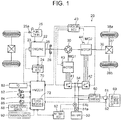
- FIG. 1 is a block diagram illustrating an outlined configuration of a hybrid vehicle 20 as an embodiment of the present invention.
- the hybrid vehicle 20 of the embodiment includes, as illustrated in the drawing, an engine 22, a planetary gear 30, motors MG1, MG2, inverters 41, 42, a battery 50, a battery charger 60, and a hybrid electronic control unit 70 (hereinafter referred to as "HVECU").
- HVECU hybrid electronic control unit
- the engine 22 is configured as an internal combustion engine that outputs motive power by using fuel such as gasoline and gas oil from a fuel tank 25.
- the operation of the engine 22 is controlled by an engine electronic control unit 24 (hereinafter referred to as "engine ECU").
- the engine ECU 24 is configured as a microprocessor having a CPU as a main component.
- the engine ECU 24 includes, in addition to the CPU, a ROM that stores processing programs, a RAM that temporarily stores data, input and output ports, and a communication port.
- the engine ECU 24 receives, through the input port, signals from various sensors needed for operation control of the engine 22, the signals including, for example, a crank angle ⁇ cr from a crank position sensor 23 that detects a rotational position of a crankshaft 26 of the engine 22.
- the engine ECU 24 outputs various control signals for operation control of the engine 22 through the output port.
- the engine ECU 24 is connected with the HVECU 70 through the communication port.
- the engine ECU 24 calculates a speed Ne of the engine 22 based on the crank angle ⁇ cr from the crank position sensor 23.
- the planetary gear 30 is configured as a single pinion-type planetary gear mechanism.
- the planetary gear 30 has a sun gear connected to a rotator of the motor MG1.
- the planetary gear 30 has a ring gear connected to a driving shaft 36 coupled with wheels 38a, 38b through a differential gear 37.
- the planetary gear 30 has a carrier connected to the crankshaft 26 of the engine 22 through a damper 28.
- the motor MG1 which is configured as a synchronous generator-motor for example, has a rotator connected to the sun gear of the planetary gear 30 as stated before.
- the inverters 41, 42 are connected with the battery 50 through an electric power line 54.
- the motors MG1, MG2 are rotationally driven when a motor electronic control unit 40 (hereinafter referred to as "motor ECU") performs switching control of a plurality of unillustrated switching elements of the inverters 41, 42.
- the motor ECU 40 is configured as a microprocessor having a CPU as a main component.
- the motor ECU 40 includes, in addition to the CPU, a ROM that stores processing programs, a RAM that temporarily stores data, input and output ports, and a communication port.
- the motor ECU 40 receives, through the input port, signals from various sensors needed for controlling the operation of the motors MG1, MG2, the signals including, for example, rotational positions ⁇ m1, ⁇ m2 from rotational position detection sensors 43, 44 that detect rotational positions of the rotators of the motors MG1, MG2.
- the motor ECU 40 outputs, through the output port, signals such as a switching control signal to a plurality of unillustrated switching elements of the inverters 41, 42.
- the motor ECU 40 is connected with the HVECU 70 through the communication port.
- the motor ECU 40 calculates the numbers of rotations Nm1, Nm2 of the motors MG1, MG2 based on the rotational positions ⁇ m1, ⁇ m2 of the rotators of the motors MG1, MG2 from the rotational position detection sensors 43, 44.
- the battery 50 is configured, for example, as a lithium-ion secondary battery or a nickel-hydrogen secondary battery.
- the battery 50 is connected with the inverters 41, 42 through the electric power line 54 as stated before.
- the battery 50 is managed by a battery electronic control unit (hereinafter referred to as "battery ECU") 52.
- battery ECU battery electronic control unit
- the battery ECU 52 is configured as a microprocessor having a CPU as a main component.
- the battery ECU 52 includes, in addition to the CPU, a ROM that stores processing programs, a RAM that temporarily stores data, input and output ports, and a communication port.
- the battery ECU 52 receives signals from various sensors needed to manage the battery 50 through the input port. Examples of the signals include a battery voltage Vb from a voltage sensor 51a disposed between terminals of the battery 50, and a battery current Ib from a current sensor 51b attached to an output terminal of the battery 50.
- the battery ECU 52 is connected with the HVECU 70 through the communication port.
- the battery ECU 52 calculates a state of charge SOC based on an integrated value of the battery current Ib from the current sensor 51b.
- the state of charge SOC refers to a ratio of capacity of electric power dischargeable from the battery 50 to the total capacity of the battery 50.
- the battery charger 60 is connected to the electric power line 54 and is configured to be able to perform external charging of the battery 50 with electric power from an external power supply 69, such as a household power supply and an industrial power supply, when a power supply plug 61 of the battery charger 60 is connected to the external power supply 69 at a charging point such as a residence and a charging station.
- an external power supply 69 such as a household power supply and an industrial power supply
- a navigation device 90 includes a main body incorporating a control unit, the control unit having a storage medium such as a hard disk, input and output ports, a communication port and the like, the storage medium storing information such as map information.
- the navigation device 90 also includes a GPS antenna configured to receive information about a present location of the vehicle, and a touch-sensitive display configured to display a variety of information, such as the information about the present location of the vehicle and a travel route to a destination and to enable an operator to input various instructions.
- the map information is stored as a database including service information (such as sightseeing information, parking area information, and charging station information) and traffic information on each preset traveling section (such as sections between signaling devices and between junctions).
- the traffic information includes distance information, width information, area information (urban areas and suburban areas), classification information (general roads and highways), slope information, legal speeds, and the number of signaling devices.
- As the service information a residential parking space and desired locations can be registered as registered locations.
- the navigation device 90 searches for a travel route from the present location of the vehicle to the destination based on the map information, the present location of the vehicle and the destination, and outputs the searched travel route on the display to provide route guidance.
- the navigation device 90 also calculates route information (such as a remaining distance Ln to the destination, and a direction Dn of the destination) for the travel route.
- the HVECU 70 is configured as a microprocessor having a CPU as a main component.
- the electronic control unit 70 includes, in addition to the CPU, a ROM that stores processing programs, a RAM that temporarily stores data, a flash memory 72, input and output ports, and a communication port.
- the HVECU 70 receives signals from various sensors through the input port. Examples of the signals input into the HVECU 70 include an ignition signal from an ignition switch 80, a shift position SP from a shift position sensor 82, an accelerator opening Acc from an accelerator pedal position sensor 84, a brake pedal position BP from a brake pedal position sensor 86, and a vehicle speed V from a vehicle speed sensor 88.
- the examples of the signals also include a fuel quantity Qf from a fuel gauge 25a attached to the fuel tank 25, a connection signal SWC from a connection switch 62 attached to the power supply plug 61 so as to determine whether or not the power supply plug 61 is connected to the external power supply 69.
- the HVECU 70 outputs signals such as a control signal to the battery charger 60 through the output port. As described before, the HVECU 70 is connected with the engine ECU 24, the motor ECU 40, and the battery ECU 52 through the communication port. When fuel is supplied to the fuel tank 25, the HVECU 70 calculates a fuel supply quantity Qin based on the fuel quantity Qf from the fuel gauge 25a.
- hybrid traveling HV traveling
- electric traveling EV traveling
- CD mode Charge Depleting
- CS Charge Sustaining
- the CD mode is a mode that prioritizes the EV traveling more than the CS mode.
- the HV traveling is a mode of traveling involving operation of the engine 22.
- the EV traveling is a mode of traveling without involving operation of the engine 22.
- the HVECU 70 controls the battery charger 60 such that the battery 50 is charged with electric power from the external power supply 69 when the power supply plug 61 is connected to the external power supply 69 while the vehicle is parked in a charging point such as a residence and a charging station with a system of the vehicle being turned off (the system being stopped). If the state of charge SOC of the battery 50 is larger than a threshold Shv1 (that is a value such as 45%, 50%, and 55%) when the system is turned on (the system is started), the vehicle travels in the CD mode until the state of charge SOC of the battery 50 reaches a thresholds Shv2 (that is a value such as 25%, 30%, and 35%) or less.
- a thresholds Shv1 that is a value such as 45%, 50%, and 55%)
- Shv2 that is a value such as 25%, 30%, and 35%) or less.
- the vehicle After the state of charge SOC of the battery 50 reaches the threshold Shv2 or less, the vehicle travels in the CS mode until the system is turned off. When the state of charge SOC of the battery 50 is equal to or less the threshold Shv when the system is turned on, the vehicle travels in the CS mode until the system is turned off.
- FIG. 2 is a flowchart illustrating one example of a charging date storage processing routine executed by the HVECU 70.
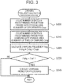
- FIG. 3 is a flowchart illustrating one example of a charging frequency calculation processing routine executed by the HVECU 70.
- the charging date storage processing routine and the charging frequency calculation processing routine are executed when the vehicle is parked and the system is turned off (system is stopped), and then the system is turned on (system is started). A detailed description will be provided in sequence.
- the HVECU 70 When the charging date storage processing routine is executed, the HVECU 70 first acquires a parking position from the navigation device 90 (step S100) and determines whether the acquired parking location is a residential parking space or a charging station (step S110). When the parking location is not the residential parking space nor the charging station, it is determined that the vehicle is parked at a location where external charging is not available, and the present routine is ended. When the parking location is the residential parking space or the charging station, it is determined that the vehicle is parked in the location where external charging is available, and a present date is stored in a parking date storage area predetermined in the flash memory 72 (step S120). Then, it is determined whether or not external charging was performed (step S130).
- Whether or not the external charging was performed can be determined based on a connection signal SWC from the connection switch 62 indicative of connection between the power supply plug 61 of the battery charger 60 and the external power supply 69 and based on whether or not the state of charge SOC of the battery 50 was increased from the SOC at the time when the system was turned off.
- the pertinent date is stored in the charging date storage area predetermined in the flash memory 72 (step S140), and the present routine is ended.
- the present routine is ended without the date being stored.
- the HVECU 70 When the charging frequency calculation processing routine is executed, the HVECU 70 first searches for dates within a predetermined period (for example, a period of past 30 days, and a period of past 30 trips) from the parking date storage area of the flash memory 72, and counts the number of the dates as the number of opportunities Copp (step S200). Next, the HVECU 70 searches for dates within the same period (predetermined period) from the charging date storage area of the flash memory 72, and counts the number of dates as the number of times of charging Cchg (step S210). The HVECU 70 then divides the number of times of charging Cchg by the number of opportunities Copp to calculate a charging frequency Fchg, and stores the charging frequency Fchg in a prescribed area of the flash memory 72 (step S220).
- a predetermined period for example, a period of past 30 days, and a period of past 30 trips
- the charging frequency Fchg is a ratio of the number of times of external charging performed to the number of opportunities where the external charging is available in the predetermined period, it can be determined that as the ratio is larger, utilization of the external charging is promoted more. Accordingly, the ratio can be used as an index that can offer more accurate determination regarding the utilization status of the external charging.
- the charging frequency Fchg is compared with a threshold Fref (step S230). When the charging frequency Fchg is equal to or larger than the threshold Fref, it is determined that the utilization status of the external charging is sufficient and the present routine is ended. When the charging frequency Fchg is less than the threshold Fref, it is determined that the utilization status of the external charging is not sufficient.
- some processing is conducted to promote the external charging, such as notification processing to perform processing such as announcement of a message "Use an external power supply to charge the vehicle", and function restriction processing to perform processing such as restricting the torque necessary for traveling (step S240), and the present routine is ended.
- the number of opportunities Copp and the number of times of charging Cchg are obtained, the number of opportunities Copp being counted as the number of opportunities where external charging of a vehicle parked in a residential parking space or a charging station is available in a predetermined period, the number of times of charging Cchg being counted as the number of times of the external charging performed in the opportunities where the external charging is available in the same predetermined period.
- the number of times of charging Cchg is then divided by the number of opportunities Copp to calculate and store the charging frequency Fchg.
- the charging frequency Fchg is a ratio of the number of times that the external charging was performed to the number of opportunities where the external charging is available in the predetermined period, the ratio is used as an index that can offer more accurate determination regarding the utilization status of the external charging. As a result, various processing to promote external charging can be executed more properly.
- the residential parking space and the charging station are used as a parking location where the number of opportunities Copp is counted.
- a location to count the number of opportunities Copp may be a charging station within a specified distance (such as 3 km or 5 km) from the residential parking space and the residence, or may be a charging station registered in advance as a regular charging location.
- the hybrid vehicle 20 of the embodiment includes the battery charger 60 that charges the battery 50 with the power supply plug 61 being connected to the external power supply 69.
- the hybrid vehicle 20 may include a battery charger that charges the battery 50 by receiving electric power from the external power supply 69 in a non-contact manner.
- the hybrid vehicle 20 of the embodiment is configured such that the engine 22, the motor MG1, and the driving shaft 36 are connected to the planetary gear 30, and the driving shaft 36 is connected to the motor MG2.
- the present invention may be configured such that a driving shaft 36 coupled with wheels 38a, 38b is connected to a motor MG through a transmission 230, and a rotating shaft of the motor MG is connected to an engine 22 through a clutch 229.
- motive power from the engine 22 may be output to the driving shaft 36 through the rotating shaft of the motor MG and the transmission 230
- motive power from the motor MG may be output to the driving shaft through the transmission 230.
- the present invention may also be configured as so-called a series-hybrid vehicle. That is, the present invention may be a hybrid vehicle of any configuration as long as the hybrid vehicle includes an engine, a motor, a battery, and a battery charger connected to an external power supply to charge the battery.
- the engine 22 corresponds to “the engine”
- the fuel tank 25 corresponds to “the fuel tank”
- the motor MG2 corresponds to “the motor”
- the battery 50 corresponds to “the battery”
- the battery charger 60 corresponds to “the battery charger”
- the HVECU 70 that executes the charging date storage processing routine in FIG. 2 and the charging frequency calculation processing routine in FIG. 3 corresponds to "the control unit”.
- the present invention is applicable in the fields such as manufacturing of the hybrid vehicle.
- the number of opportunities where external charging of a vehicle parked in a residential parking space or a charging station in a predetermined period is available is counted as the number of opportunities (S200), and the number of times of the external charging performed in the opportunities in the same predetermined period is counted as the number of times of charging (S210).
- the number of times of charging is then divided by the number of opportunities to calculate and store a charging frequency (S220). Since the charging frequency is a ratio of the number of times that the external charging was performed to the number of opportunities where the external charging is available in the predetermined period, the ratio is used as an index that can offer more accurate determination regarding an external charging utilization status.
Abstract
Description
- The present invention relates to hybrid vehicles, and more particularly relates to a hybrid vehicle configured to charge a battery and supply fuel to a fuel tank.
- Conventionally, as a hybrid vehicle of this type, there has been proposed a vehicle that restricts at least one output out of an output of an electric motor and an output of an internal combustion engine when change in a parameter, which corresponds to fuel consumption consumed by the internal combustion engine from the time of external charging of the battery, reaches a specified value (see, for example,
Japanese Patent Application Publication No. 8-19114 - However, since the aforementioned hybrid vehicle uses the parameter corresponding to fuel consumption consumed by the internal combustion engine from the time of external charging of the battery, it is sometimes difficult to properly determine how much electric travel, which does not involve operation of the internal combustion engine, is being performed or how appropriately the external charging is being conducted.
- A hybrid vehicle of the present invention provides an index that can offer more appropriate determination regarding a utilization status of external charging.
- The hybrid vehicle in a mode of the present invention includes an engine, a fuel tank configured to supply fuel to the engine, a motor, a battery configured to be able to supply electric power to the motor, a battery charger configured to be able to perform external charging that charges the battery using an external power supply, and control means, wherein the control means is configured to count the number of opportunities where the external charging of the vehicle is available as the number of charging opportunities and to count the number of times of charging as the number of times that the vehicle performed the external charging in a predetermined period, and the control means is configured to calculate and store a charging frequency as a ratio of the number of times of charging to the number of opportunities. The mode of the present invention can also be defined as below. A hybrid vehicle includes: an engine; a fuel tank configured to supply fuel to the engine; a motor; a battery configured to supply electric power to the motor; a battery charger configured to perform external charging that charges the battery using an external power supply; and an electronic control unit configured to i) count the number of times of charging opportunities that the vehicle is in a state where the external charging is available in a predetermined period, as the number of times of opportunities, ii) count the number of times of the external charging that the vehicle performed in the predetermine period as the number of times of charging, and iii) calculate and store a ratio of the number of times of charging to the number of times of opportunities, as a charging frequency.
- In the hybrid vehicle in the mode of the present invention, the number of opportunities as the number of charging opportunities and the number of times of charging are counted in a predetermined period, and a charging frequency is calculated and stored as a ratio of the number of times of charging to the number of opportunities. It can be determined that as the charging frequency calculated and stored in this way is larger, utilization of external charging is promoted more. Accordingly, the charging frequency can be used as an index that can offer more accurate determination regarding a utilization status of the external charging. Here, "the predetermined period" may be a period predetermined in time, such as in one month or in two months, or may be a period predetermined in terms of opportunities, such as in twenty trips or in thirty trips.
- In such a hybrid vehicle in the mode of the present invention, the control unit may be configured to count the number of times that the vehicle is parked in a residential parking space and a charging station or in one of the residential parking space and the charging station as the number of opportunities. With the configuration, the charging frequency is the number of times of charging with respect to the number of times that the vehicle is parked in the residential parking space or the charging station in a predetermined period. As a result, it becomes possible to offer more accurate determination regarding the utilization status of the external charging in the residential parking space or the charging station.
- In the hybrid vehicle in the mode of the present invention, the control unit may be configured to count the number of times that the vehicle is parked in a charging station within a prescribed distance from a residence as the number of opportunities, or may be configured to count the number of times that the vehicle is parked in a charging station registered in advance as the number of opportunities. With the configuration, the charging frequency is the number of times of charging with respect to the number of times that the vehicle is parked in the charging station within a specified distance from the residence in the predetermined period, or is the number of times of charging with respect to the number of times that the vehicle is parked in the charging station registered in advance in the predetermined period. Accordingly, it becomes possible to offer more accurate determination regarding the utilization status of the external charging in the charging station within a specified distance from the residence or the utilization status of the external charging in the charging station registered in advance.
- Features, advantages, and technical and industrial significance of exemplary embodiments of the invention will be described below with reference to the accompanying drawings, in which like numerals denote like elements, and wherein:
-
FIG. 1 is a block diagram illustrating an outlined configuration of a hybrid vehicle as an embodiment of the present invention; -
FIG. 2 is a flowchart illustrating one example of a charging date storage processing routine executed by an HVECU; -
FIG. 3 is a flowchart illustrating one example of a charging frequency calculation processing routine executed by the HVECU; and -
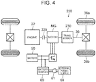
FIG. 4 is a block diagram illustrating an outlined configuration of a hybrid vehicle in a modification. - Now, a mode for carrying out the present invention will be described in detail based on an embodiment.
-
FIG. 1 is a block diagram illustrating an outlined configuration of ahybrid vehicle 20 as an embodiment of the present invention. Thehybrid vehicle 20 of the embodiment includes, as illustrated in the drawing, anengine 22, aplanetary gear 30, motors MG1, MG2,inverters battery 50, abattery charger 60, and a hybrid electronic control unit 70 (hereinafter referred to as "HVECU"). - The
engine 22 is configured as an internal combustion engine that outputs motive power by using fuel such as gasoline and gas oil from afuel tank 25. The operation of theengine 22 is controlled by an engine electronic control unit 24 (hereinafter referred to as "engine ECU"). - Although not illustrated, the engine ECU 24 is configured as a microprocessor having a CPU as a main component. The engine ECU 24 includes, in addition to the CPU, a ROM that stores processing programs, a RAM that temporarily stores data, input and output ports, and a communication port. The engine ECU 24 receives, through the input port, signals from various sensors needed for operation control of the
engine 22, the signals including, for example, a crank angle θcr from acrank position sensor 23 that detects a rotational position of acrankshaft 26 of theengine 22. The engine ECU 24 outputs various control signals for operation control of theengine 22 through the output port. The engine ECU 24 is connected with the HVECU 70 through the communication port. The engine ECU 24 calculates a speed Ne of theengine 22 based on the crank angle θcr from thecrank position sensor 23. - The
planetary gear 30 is configured as a single pinion-type planetary gear mechanism. Theplanetary gear 30 has a sun gear connected to a rotator of the motor MG1. Theplanetary gear 30 has a ring gear connected to adriving shaft 36 coupled withwheels differential gear 37. Theplanetary gear 30 has a carrier connected to thecrankshaft 26 of theengine 22 through adamper 28. - The motor MG1, which is configured as a synchronous generator-motor for example, has a rotator connected to the sun gear of the
planetary gear 30 as stated before. The motor MG2, which is configured as a synchronous generator-motor for example, has a rotator connected to thedriving shaft 36. Theinverters battery 50 through anelectric power line 54. The motors MG1, MG2 are rotationally driven when a motor electronic control unit 40 (hereinafter referred to as "motor ECU") performs switching control of a plurality of unillustrated switching elements of theinverters - Although not illustrated, the motor ECU 40 is configured as a microprocessor having a CPU as a main component. The motor ECU 40 includes, in addition to the CPU, a ROM that stores processing programs, a RAM that temporarily stores data, input and output ports, and a communication port. The motor ECU 40 receives, through the input port, signals from various sensors needed for controlling the operation of the motors MG1, MG2, the signals including, for example, rotational positions θm1, θm2 from rotational
position detection sensors motor ECU 40 outputs, through the output port, signals such as a switching control signal to a plurality of unillustrated switching elements of theinverters position detection sensors - The
battery 50 is configured, for example, as a lithium-ion secondary battery or a nickel-hydrogen secondary battery. Thebattery 50 is connected with theinverters electric power line 54 as stated before. Thebattery 50 is managed by a battery electronic control unit (hereinafter referred to as "battery ECU") 52. - Although not illustrated, the
battery ECU 52 is configured as a microprocessor having a CPU as a main component. Thebattery ECU 52 includes, in addition to the CPU, a ROM that stores processing programs, a RAM that temporarily stores data, input and output ports, and a communication port. Thebattery ECU 52 receives signals from various sensors needed to manage thebattery 50 through the input port. Examples of the signals include a battery voltage Vb from avoltage sensor 51a disposed between terminals of thebattery 50, and a battery current Ib from acurrent sensor 51b attached to an output terminal of thebattery 50. Thebattery ECU 52 is connected with the HVECU 70 through the communication port. Thebattery ECU 52 calculates a state of charge SOC based on an integrated value of the battery current Ib from thecurrent sensor 51b. The state of charge SOC refers to a ratio of capacity of electric power dischargeable from thebattery 50 to the total capacity of thebattery 50. - The
battery charger 60 is connected to theelectric power line 54 and is configured to be able to perform external charging of thebattery 50 with electric power from anexternal power supply 69, such as a household power supply and an industrial power supply, when apower supply plug 61 of thebattery charger 60 is connected to theexternal power supply 69 at a charging point such as a residence and a charging station. - A
navigation device 90 includes a main body incorporating a control unit, the control unit having a storage medium such as a hard disk, input and output ports, a communication port and the like, the storage medium storing information such as map information. Thenavigation device 90 also includes a GPS antenna configured to receive information about a present location of the vehicle, and a touch-sensitive display configured to display a variety of information, such as the information about the present location of the vehicle and a travel route to a destination and to enable an operator to input various instructions. Here, the map information is stored as a database including service information (such as sightseeing information, parking area information, and charging station information) and traffic information on each preset traveling section (such as sections between signaling devices and between junctions). The traffic information includes distance information, width information, area information (urban areas and suburban areas), classification information (general roads and highways), slope information, legal speeds, and the number of signaling devices. As the service information, a residential parking space and desired locations can be registered as registered locations. When a destination is set by the operator, thenavigation device 90 searches for a travel route from the present location of the vehicle to the destination based on the map information, the present location of the vehicle and the destination, and outputs the searched travel route on the display to provide route guidance. Thenavigation device 90 also calculates route information (such as a remaining distance Ln to the destination, and a direction Dn of the destination) for the travel route. - Although not illustrated, the
HVECU 70 is configured as a microprocessor having a CPU as a main component. Theelectronic control unit 70 includes, in addition to the CPU, a ROM that stores processing programs, a RAM that temporarily stores data, aflash memory 72, input and output ports, and a communication port. TheHVECU 70 receives signals from various sensors through the input port. Examples of the signals input into theHVECU 70 include an ignition signal from anignition switch 80, a shift position SP from ashift position sensor 82, an accelerator opening Acc from an acceleratorpedal position sensor 84, a brake pedal position BP from a brakepedal position sensor 86, and a vehicle speed V from avehicle speed sensor 88. The examples of the signals also include a fuel quantity Qf from afuel gauge 25a attached to thefuel tank 25, a connection signal SWC from aconnection switch 62 attached to thepower supply plug 61 so as to determine whether or not thepower supply plug 61 is connected to theexternal power supply 69. TheHVECU 70 outputs signals such as a control signal to thebattery charger 60 through the output port. As described before, theHVECU 70 is connected with theengine ECU 24, themotor ECU 40, and thebattery ECU 52 through the communication port. When fuel is supplied to thefuel tank 25, theHVECU 70 calculates a fuel supply quantity Qin based on the fuel quantity Qf from thefuel gauge 25a. - In the thus-configured
hybrid vehicle 20 of the embodiment, hybrid traveling (HV traveling) or electric traveling (EV traveling) is performed in a Charge Depleting (CD) mode or a Charge Sustaining (CS) mode. Here, the CD mode is a mode that prioritizes the EV traveling more than the CS mode. The HV traveling is a mode of traveling involving operation of theengine 22. The EV traveling is a mode of traveling without involving operation of theengine 22. - In the embodiment, the
HVECU 70 controls thebattery charger 60 such that thebattery 50 is charged with electric power from theexternal power supply 69 when thepower supply plug 61 is connected to theexternal power supply 69 while the vehicle is parked in a charging point such as a residence and a charging station with a system of the vehicle being turned off (the system being stopped). If the state of charge SOC of thebattery 50 is larger than a threshold Shv1 (that is a value such as 45%, 50%, and 55%) when the system is turned on (the system is started), the vehicle travels in the CD mode until the state of charge SOC of thebattery 50 reaches a thresholds Shv2 (that is a value such as 25%, 30%, and 35%) or less. After the state of charge SOC of thebattery 50 reaches the threshold Shv2 or less, the vehicle travels in the CS mode until the system is turned off. When the state of charge SOC of thebattery 50 is equal to or less the threshold Shv when the system is turned on, the vehicle travels in the CS mode until the system is turned off. - A description is now given of operation of the thus-configured
hybrid vehicle 20 of the embodiment, and particularly the operation of calculating and storing a charging frequency Fchg used as a utilization index of charging (external charging) of thebattery 50 by thebattery charger 60.FIG. 2 is a flowchart illustrating one example of a charging date storage processing routine executed by theHVECU 70.FIG. 3 is a flowchart illustrating one example of a charging frequency calculation processing routine executed by theHVECU 70. In the embodiment, the charging date storage processing routine and the charging frequency calculation processing routine are executed when the vehicle is parked and the system is turned off (system is stopped), and then the system is turned on (system is started). A detailed description will be provided in sequence. - When the charging date storage processing routine is executed, the
HVECU 70 first acquires a parking position from the navigation device 90 (step S100) and determines whether the acquired parking location is a residential parking space or a charging station (step S110). When the parking location is not the residential parking space nor the charging station, it is determined that the vehicle is parked at a location where external charging is not available, and the present routine is ended. When the parking location is the residential parking space or the charging station, it is determined that the vehicle is parked in the location where external charging is available, and a present date is stored in a parking date storage area predetermined in the flash memory 72 (step S120). Then, it is determined whether or not external charging was performed (step S130). Whether or not the external charging was performed can be determined based on a connection signal SWC from theconnection switch 62 indicative of connection between thepower supply plug 61 of thebattery charger 60 and theexternal power supply 69 and based on whether or not the state of charge SOC of thebattery 50 was increased from the SOC at the time when the system was turned off. When external charging was performed, the pertinent date is stored in the charging date storage area predetermined in the flash memory 72 (step S140), and the present routine is ended. When the external charging was not performed, the present routine is ended without the date being stored. - When the charging frequency calculation processing routine is executed, the
HVECU 70 first searches for dates within a predetermined period (for example, a period of past 30 days, and a period of past 30 trips) from the parking date storage area of theflash memory 72, and counts the number of the dates as the number of opportunities Copp (step S200). Next, theHVECU 70 searches for dates within the same period (predetermined period) from the charging date storage area of theflash memory 72, and counts the number of dates as the number of times of charging Cchg (step S210). TheHVECU 70 then divides the number of times of charging Cchg by the number of opportunities Copp to calculate a charging frequency Fchg, and stores the charging frequency Fchg in a prescribed area of the flash memory 72 (step S220). Since the charging frequency Fchg is a ratio of the number of times of external charging performed to the number of opportunities where the external charging is available in the predetermined period, it can be determined that as the ratio is larger, utilization of the external charging is promoted more. Accordingly, the ratio can be used as an index that can offer more accurate determination regarding the utilization status of the external charging. Once the charging frequency Fchg is calculated and stored in this way, the charging frequency Fchg is compared with a threshold Fref (step S230). When the charging frequency Fchg is equal to or larger than the threshold Fref, it is determined that the utilization status of the external charging is sufficient and the present routine is ended. When the charging frequency Fchg is less than the threshold Fref, it is determined that the utilization status of the external charging is not sufficient. Accordingly, some processing is conducted to promote the external charging, such as notification processing to perform processing such as announcement of a message "Use an external power supply to charge the vehicle", and function restriction processing to perform processing such as restricting the torque necessary for traveling (step S240), and the present routine is ended. - In the
hybrid vehicle 20 in the embodiment described in the foregoing, the number of opportunities Copp and the number of times of charging Cchg are obtained, the number of opportunities Copp being counted as the number of opportunities where external charging of a vehicle parked in a residential parking space or a charging station is available in a predetermined period, the number of times of charging Cchg being counted as the number of times of the external charging performed in the opportunities where the external charging is available in the same predetermined period. The number of times of charging Cchg is then divided by the number of opportunities Copp to calculate and store the charging frequency Fchg. Since the charging frequency Fchg is a ratio of the number of times that the external charging was performed to the number of opportunities where the external charging is available in the predetermined period, the ratio is used as an index that can offer more accurate determination regarding the utilization status of the external charging. As a result, various processing to promote external charging can be executed more properly. - In the
hybrid vehicle 20 of the embodiment, the residential parking space and the charging station are used as a parking location where the number of opportunities Copp is counted. However, a location to count the number of opportunities Copp may be a charging station within a specified distance (such as 3 km or 5 km) from the residential parking space and the residence, or may be a charging station registered in advance as a regular charging location. - The
hybrid vehicle 20 of the embodiment includes thebattery charger 60 that charges thebattery 50 with thepower supply plug 61 being connected to theexternal power supply 69. However, thehybrid vehicle 20 may include a battery charger that charges thebattery 50 by receiving electric power from theexternal power supply 69 in a non-contact manner. - The
hybrid vehicle 20 of the embodiment is configured such that theengine 22, the motor MG1, and the drivingshaft 36 are connected to theplanetary gear 30, and the drivingshaft 36 is connected to the motor MG2. Like ahybrid vehicle 220 in a modification illustrated inFIG. 4 , the present invention may be configured such that a drivingshaft 36 coupled withwheels transmission 230, and a rotating shaft of the motor MG is connected to anengine 22 through a clutch 229. In this case, motive power from theengine 22 may be output to the drivingshaft 36 through the rotating shaft of the motor MG and thetransmission 230, and motive power from the motor MG may be output to the driving shaft through thetransmission 230. The present invention may also be configured as so-called a series-hybrid vehicle. That is, the present invention may be a hybrid vehicle of any configuration as long as the hybrid vehicle includes an engine, a motor, a battery, and a battery charger connected to an external power supply to charge the battery. - Correspondence relation between the main elements of the embodiment and the main elements of the present invention described in Summary of the Invention will be described. In the embodiment, the
engine 22 corresponds to "the engine", thefuel tank 25 corresponds to "the fuel tank", the motor MG2 corresponds to "the motor", thebattery 50 corresponds to "the battery", thebattery charger 60 corresponds to "the battery charger", and theHVECU 70 that executes the charging date storage processing routine inFIG. 2 and the charging frequency calculation processing routine inFIG. 3 corresponds to "the control unit". - Since the embodiment is one example for specific description of the mode for carrying out the present invention described in Summary of the Invention, the correspondence relation between the main elements of the embodiment and the main elements of the present invention described in Summary of the Invention is not intended to limit the elements of the invention described in Summary of the Invention. More specifically, the invention disclosed in Summary of the Invention should be interpreted based on the description therein, and the embodiment is merely a specific example of the invention disclosed in Summary of the Invention.
- Although the mode for carrying out the present invention has been described using the embodiment, the present invention is not limited in any manner to the embodiment disclosed. It should naturally be understood that the present invention can be carried out in various modes without departing from the scope of the present invention.
- The present invention is applicable in the fields such as manufacturing of the hybrid vehicle.
The number of opportunities where external charging of a vehicle parked in a residential parking space or a charging station in a predetermined period is available is counted as the number of opportunities (S200), and the number of times of the external charging performed in the opportunities in the same predetermined period is counted as the number of times of charging (S210). The number of times of charging is then divided by the number of opportunities to calculate and store a charging frequency (S220). Since the charging frequency is a ratio of the number of times that the external charging was performed to the number of opportunities where the external charging is available in the predetermined period, the ratio is used as an index that can offer more accurate determination regarding an external charging utilization status. As a result, various processing to promote external charging can be executed more properly.
This application is a divisional application ofEuropean patent application no. 17 162 993.4 EP 3 225 491 A1 . The following items corresponding to the originally filed claims of the parent application form part of the content of this description as filed. -
- 1. A hybrid vehicle, comprising:
- an engine (22);
- a fuel tank (25) configured to supply fuel to the engine;
- a motor (MG2);
- a battery (50) configured to supply electric power to the motor;
- a battery charger (60) configured to perform external charging that charges the battery using an external power supply; and
- an electronic control unit (70) configured to
- i) count the number of times of charging opportunities that the vehicle is in a state where the external charging is available in a predetermined period, as the number of times of opportunities,
- ii) count the number of times of the external charging that the vehicle performed in the predetermine period, as the number of times of charging, and
- iii) calculate and store a ratio of the number of times of charging to the number of times of opportunities, as a charging frequency.
- 2. The hybrid vehicle according to item 1, wherein
the electronic control unit is configured to count at least one of the number of times that the vehicle is parked in a residential parking space and the number of times that the vehicle is parked in a charging station as the number of times of opportunities. - 3. The hybrid vehicle according to item 1, wherein
the electronic control unit is configured to count the number of times that the vehicle is parked in a charging station within a prescribed distance from a residence, as the number of times of opportunities. - 4. The hybrid vehicle according to item 1, wherein
the electronic control unit is configured to count the number of times that the vehicle is parked in a charging station registered in advance, as the number of times of opportunities.
Claims (5)
- An electronic control unit (70) configured toi) count the number of times of charging opportunities that a hybrid vehicle is in a state where external charging is available in a predetermined period, as the number of times of opportunities,ii) count the number of times of the external charging that the vehicle performed in the predetermined period, as the number of times of charging, andiii) calculate and store a ratio of the number of times of charging to the number of times of opportunities, as a charging frequency.
- The electronic control unit (70) according to claim 1, further configured to count at least one of the number of times that the vehicle is parked in a residential parking space and the number of times that the vehicle is parked in a charging station as the number of times of opportunities.
- The electronic control unit (70) according to claim 1, further configured to count the number of times that the vehicle is parked in a charging station within a prescribed distance from a residence, as the number of times of opportunities.
- The electronic control unit (70) according to claim 1, further configured to count the number of times that the vehicle is parked in a charging station registered in advance, as the number of times of opportunities.
- The electronic control unit (70) according to any one of claims 1 to 4, wherein the predetermined period is a period predetermined in time or a period predetermined in opportunities.
Applications Claiming Priority (2)
| Application Number | Priority Date | Filing Date | Title |
|---|---|---|---|
| JP2016069253A JP2017178083A (en) | 2016-03-30 | 2016-03-30 | Hybrid motorcar |
| EP17162993.4A EP3225491B1 (en) | 2016-03-30 | 2017-03-27 | Hybrid vehicle |
Related Parent Applications (2)
| Application Number | Title | Priority Date | Filing Date |
|---|---|---|---|
| EP17162993.4A Division EP3225491B1 (en) | 2016-03-30 | 2017-03-27 | Hybrid vehicle |
| EP17162993.4A Division-Into EP3225491B1 (en) | 2016-03-30 | 2017-03-27 | Hybrid vehicle |
Publications (2)
| Publication Number | Publication Date |
|---|---|
| EP3936402A2 true EP3936402A2 (en) | 2022-01-12 |
| EP3936402A3 EP3936402A3 (en) | 2022-04-27 |
Family
ID=58454871
Family Applications (2)
| Application Number | Title | Priority Date | Filing Date |
|---|---|---|---|
| EP21193923.6A Pending EP3936402A3 (en) | 2016-03-30 | 2017-03-27 | Electronic control unit for a hybrid vehicle |
| EP17162993.4A Active EP3225491B1 (en) | 2016-03-30 | 2017-03-27 | Hybrid vehicle |
Family Applications After (1)
| Application Number | Title | Priority Date | Filing Date |
|---|---|---|---|
| EP17162993.4A Active EP3225491B1 (en) | 2016-03-30 | 2017-03-27 | Hybrid vehicle |
Country Status (4)
| Country | Link |
|---|---|
| US (2) | US10384549B2 (en) |
| EP (2) | EP3936402A3 (en) |
| JP (1) | JP2017178083A (en) |
| CN (1) | CN107399240A (en) |
Families Citing this family (5)
| Publication number | Priority date | Publication date | Assignee | Title |
|---|---|---|---|---|
| JP2017178083A (en) | 2016-03-30 | 2017-10-05 | トヨタ自動車株式会社 | Hybrid motorcar |
| JP2018114874A (en) * | 2017-01-19 | 2018-07-26 | トヨタ自動車株式会社 | Hybrid vehicle |
| JP6897528B2 (en) * | 2017-12-05 | 2021-06-30 | トヨタ自動車株式会社 | Hybrid vehicle control device |
| DE102019121415A1 (en) * | 2019-08-08 | 2021-02-11 | Bayerische Motoren Werke Aktiengesellschaft | Hybrid vehicle with an internal combustion engine drive |
| JP7371596B2 (en) * | 2020-09-23 | 2023-10-31 | トヨタ自動車株式会社 | hybrid vehicle |
Citations (2)
| Publication number | Priority date | Publication date | Assignee | Title |
|---|---|---|---|---|
| JPH0819114A (en) | 1994-04-28 | 1996-01-19 | Mitsubishi Motors Corp | Fuel use regulating type hybrid electric motor vehicle |
| EP3225491A1 (en) | 2016-03-30 | 2017-10-04 | Toyota Jidosha Kabushiki Kaisha | Hybrid vehicle |
Family Cites Families (40)
| Publication number | Priority date | Publication date | Assignee | Title |
|---|---|---|---|---|
| RU2048309C1 (en) | 1992-11-02 | 1995-11-20 | Иван Федорович Маслянцев | Electric vehicle |
| JPH08237810A (en) | 1995-02-27 | 1996-09-13 | Aqueous Res:Kk | Hybrid vehicle |
| JP3013764B2 (en) | 1995-10-03 | 2000-02-28 | 三菱自動車工業株式会社 | Charge and discharge control device for hybrid electric vehicles |
| US6081097A (en) * | 1998-01-19 | 2000-06-27 | Matsushita Electric Industrial Co., Ltd. | Method for charging lithium secondary battery |
| US6127798A (en) | 1998-04-14 | 2000-10-03 | Lansang; Enrique | Electric power supply having two electrical battery storage means for vehicles and other applications |
| JP2000032606A (en) | 1998-07-14 | 2000-01-28 | Toyota Motor Corp | Vehicle |
| JP2001268719A (en) | 2000-03-23 | 2001-09-28 | Toyota Motor Corp | Battery charging controller for hybrid vehicle |
| JP4308408B2 (en) | 2000-04-28 | 2009-08-05 | パナソニック株式会社 | Secondary battery input / output controller |
| ES2275854T3 (en) | 2001-04-05 | 2007-06-16 | Electrovaya Inc. | ENERGY STORAGE DEVICE FOR LOADS THAT HAVE RANGES OF VARIABLE ENERGY. |
| US6814170B2 (en) | 2001-07-18 | 2004-11-09 | Nissan Motor Co., Ltd. | Hybrid vehicle |
| JP3632634B2 (en) * | 2001-07-18 | 2005-03-23 | 日産自動車株式会社 | Control device for hybrid vehicle |
| JP3617475B2 (en) | 2001-07-18 | 2005-02-02 | 日産自動車株式会社 | Control device for hybrid vehicle |
| JP4118035B2 (en) | 2001-08-03 | 2008-07-16 | トヨタ自動車株式会社 | Battery control device |
| JP4228760B2 (en) * | 2002-07-12 | 2009-02-25 | トヨタ自動車株式会社 | Battery charge state estimation device |
| JP2004229354A (en) | 2003-01-20 | 2004-08-12 | Hitachi Unisia Automotive Ltd | Controller for hybrid vehicle |
| JP4682740B2 (en) | 2005-08-08 | 2011-05-11 | トヨタ自動車株式会社 | Vehicle power supply |
| JP4736678B2 (en) * | 2005-09-29 | 2011-07-27 | トヨタ自動車株式会社 | Vehicle preferential system, electric vehicle and server |
| JP4692246B2 (en) * | 2005-11-29 | 2011-06-01 | 日産自動車株式会社 | Secondary battery input / output possible power estimation device |
| JP4274257B2 (en) | 2007-02-20 | 2009-06-03 | トヨタ自動車株式会社 | Hybrid vehicle |
| JP5181732B2 (en) * | 2007-05-02 | 2013-04-10 | 日産自動車株式会社 | Hybrid vehicle mode switching control device |
| JP2009126456A (en) * | 2007-11-27 | 2009-06-11 | Fujitsu Ten Ltd | Controller for hybrid vehicle |
| JP4450087B2 (en) * | 2008-03-31 | 2010-04-14 | トヨタ自動車株式会社 | Hybrid vehicle and control method thereof |
| JP5044524B2 (en) * | 2008-10-27 | 2012-10-10 | トヨタ自動車株式会社 | Point registration device |
| WO2010089843A1 (en) * | 2009-02-03 | 2010-08-12 | トヨタ自動車株式会社 | Charging system for vehicle and method for controlling charging system |
| US8849499B2 (en) * | 2011-01-06 | 2014-09-30 | Ford Global Technologies, Llc | Methods and systems for monitoring a vehicle's energy source |
| JP5923944B2 (en) * | 2011-01-25 | 2016-05-25 | 日産自動車株式会社 | Control device for hybrid vehicle |
| JP5673798B2 (en) * | 2011-03-24 | 2015-02-18 | トヨタ自動車株式会社 | Cord storage device and vehicle |
| JP5696708B2 (en) * | 2012-10-02 | 2015-04-08 | トヨタ自動車株式会社 | Control device for plug-in hybrid vehicle |
| JP5549726B2 (en) * | 2012-11-22 | 2014-07-16 | 三菱自動車工業株式会社 | Cruising range calculation device |
| JP6349384B2 (en) * | 2013-05-15 | 2018-06-27 | ボルボトラックコーポレーション | Method and structure for controlling charging of an energy storage system |
| WO2014196075A1 (en) * | 2013-06-07 | 2014-12-11 | 三菱電機株式会社 | Charging-discharging control device and electric vehicle |
| DE102013215208A1 (en) * | 2013-08-02 | 2015-02-05 | Ford Global Technologies, Llc | Method and device for parking assistance of a vehicle |
| EP3105743A4 (en) * | 2014-02-13 | 2018-01-24 | Recargo, Inc. | Performing actions associated with a connected vehicle |
| JP6363493B2 (en) * | 2014-12-19 | 2018-07-25 | トヨタ自動車株式会社 | Hybrid vehicle |
| JP6439722B2 (en) * | 2016-03-08 | 2018-12-19 | トヨタ自動車株式会社 | Hybrid car |
| JP6436124B2 (en) * | 2016-03-30 | 2018-12-12 | トヨタ自動車株式会社 | Hybrid car |
| JP6361681B2 (en) * | 2016-03-30 | 2018-07-25 | トヨタ自動車株式会社 | Hybrid car |
| JP6489054B2 (en) * | 2016-03-30 | 2019-03-27 | トヨタ自動車株式会社 | Hybrid car |
| JP6376164B2 (en) * | 2016-03-30 | 2018-08-22 | トヨタ自動車株式会社 | Hybrid vehicles and external systems |
| JP6399026B2 (en) * | 2016-03-30 | 2018-10-03 | トヨタ自動車株式会社 | Hybrid vehicle and linkage system |
-
2016
- 2016-03-30 JP JP2016069253A patent/JP2017178083A/en active Pending
-
2017
- 2017-03-24 US US15/468,263 patent/US10384549B2/en not_active Expired - Fee Related
- 2017-03-27 EP EP21193923.6A patent/EP3936402A3/en active Pending
- 2017-03-27 EP EP17162993.4A patent/EP3225491B1/en active Active
- 2017-03-28 CN CN201710191604.2A patent/CN107399240A/en active Pending
-
2019
- 2019-07-01 US US16/458,898 patent/US10946752B2/en active Active
Patent Citations (2)
| Publication number | Priority date | Publication date | Assignee | Title |
|---|---|---|---|---|
| JPH0819114A (en) | 1994-04-28 | 1996-01-19 | Mitsubishi Motors Corp | Fuel use regulating type hybrid electric motor vehicle |
| EP3225491A1 (en) | 2016-03-30 | 2017-10-04 | Toyota Jidosha Kabushiki Kaisha | Hybrid vehicle |
Also Published As
| Publication number | Publication date |
|---|---|
| EP3936402A3 (en) | 2022-04-27 |
| US10384549B2 (en) | 2019-08-20 |
| US20190322181A1 (en) | 2019-10-24 |
| US10946752B2 (en) | 2021-03-16 |
| EP3225491A1 (en) | 2017-10-04 |
| EP3225491B1 (en) | 2021-10-13 |
| JP2017178083A (en) | 2017-10-05 |
| US20170282726A1 (en) | 2017-10-05 |
| CN107399240A (en) | 2017-11-28 |
Similar Documents
| Publication | Publication Date | Title |
|---|---|---|
| US10328816B2 (en) | Hybrid vehicle, cooperation system, and control method for hybrid vehicle | |
| US10946752B2 (en) | Hybrid vehicle | |
| EP3225490B1 (en) | Hybrid vehicle | |
| US10336251B2 (en) | Hybrid vehicle | |
| CN109572664B (en) | Hybrid vehicle and method of controlling hybrid vehicle | |
| EP3225485A1 (en) | Hybrid vehicle | |
| JP7010039B2 (en) | Hybrid car | |
| JP2007099030A (en) | Automobile and control method thereof | |
| JP6512151B2 (en) | Hybrid car | |
| JP2017178082A (en) | Hybrid motorcar | |
| JP6642206B2 (en) | Hybrid car | |
| CN110155035B (en) | Hybrid electric vehicle | |
| JP7010038B2 (en) | Hybrid car | |
| JP7067004B2 (en) | Hybrid car | |
| JP6939628B2 (en) | Vehicle control device | |
| JP6969419B2 (en) | Hybrid car | |
| JP2021059294A (en) | Hybrid vehicle | |
| JP2021084541A (en) | Vehicle control device | |
| JP2020120495A (en) | vehicle | |
| JP2017178081A (en) | Hybrid motorcar |
Legal Events
| Date | Code | Title | Description |
|---|---|---|---|
| PUAI | Public reference made under article 153(3) epc to a published international application that has entered the european phase |
Free format text: ORIGINAL CODE: 0009012 |
|
| STAA | Information on the status of an ep patent application or granted ep patent |
Free format text: STATUS: REQUEST FOR EXAMINATION WAS MADE |
|
| 17P | Request for examination filed |
Effective date: 20210831 |
|
| AC | Divisional application: reference to earlier application |
Ref document number: 3225491 Country of ref document: EP Kind code of ref document: P |
|
| AK | Designated contracting states |
Kind code of ref document: A2 Designated state(s): AL AT BE BG CH CY CZ DE DK EE ES FI FR GB GR HR HU IE IS IT LI LT LU LV MC MK MT NL NO PL PT RO RS SE SI SK SM TR |
|
| PUAL | Search report despatched |
Free format text: ORIGINAL CODE: 0009013 |
|
| AK | Designated contracting states |
Kind code of ref document: A3 Designated state(s): AL AT BE BG CH CY CZ DE DK EE ES FI FR GB GR HR HU IE IS IT LI LT LU LV MC MK MT NL NO PL PT RO RS SE SI SK SM TR |
|
| RIC1 | Information provided on ipc code assigned before grant |
Ipc: B60W 40/09 20120101AFI20220319BHEP |