EP3935985B1 - Skischuhsystem - Google Patents
Skischuhsystem Download PDFInfo
- Publication number
- EP3935985B1 EP3935985B1 EP21166660.7A EP21166660A EP3935985B1 EP 3935985 B1 EP3935985 B1 EP 3935985B1 EP 21166660 A EP21166660 A EP 21166660A EP 3935985 B1 EP3935985 B1 EP 3935985B1
- Authority
- EP
- European Patent Office
- Prior art keywords
- sole
- connecting structure
- pivot axis
- ski
- boot
- Prior art date
- Legal status (The legal status is an assumption and is not a legal conclusion. Google has not performed a legal analysis and makes no representation as to the accuracy of the status listed.)
- Active
Links
Images


Classifications
-
- A—HUMAN NECESSITIES
- A43—FOOTWEAR
- A43B—CHARACTERISTIC FEATURES OF FOOTWEAR; PARTS OF FOOTWEAR
- A43B5/00—Footwear for sporting purposes
- A43B5/04—Ski or like boots
- A43B5/0411—Ski or like boots for cross-country
- A43B5/0413—Adaptations for soles or accessories associated with soles for cross-country bindings
Definitions
- the invention relates to a ski boot system comprising a ski boot and at least two connecting structures each for securing the ski boot to a binding of a ski or board.
- the ski boot system i.e. the ski boot and the connecting structures, may in particular be configured for Nordic skiing and any closely related sports such as roller skiing.
- a Nordic ski boot system it may advantageously be configured for classic cross-country skiing and/or skate skiing and/or roller skiing.
- a Nordic ski boot system can, as an alternative, be configured for light touring skiing which involves cross-country skis and Nordic touring boots which are slightly wider in the lateral direction than the skis and boots for classic cross-country skiing.
- Nordic ski boots are secured to the ski binding and via the ski binding to the ski such that the ski boot can pivot about a pivot axis located in the forefoot region of the ski boot.
- the skiing experience is affected by where and how the ski boot is secured to the ski via the ski binding. Locating the pivot axis closer to the ski boot tip increases the gliding length for each kick. Moving the pivot axis rearwards makes it easier to maintain or increase the cadence.
- the optimal position of the pivot axis depends on external factors, such as the profile of the terrain and snow conditions, and individual factors, such as the skier's size, body weight, body strength and experience. A single ski boot can hardly meet the various and sometimes contradicting demands resulting from the different external conditions and personal factors.
- US 2012/0151801 A1 proposes a ski boot in combination with a connecting structure that comprises a first rod and a second rod spaced from one another in the longitudinal direction of the ski boot.
- the connecting structure is releasably mounted on the sole of the ski boot by means of a screw connection.
- the connecting structure can be mounted with either the first rod or the second rod in front of the respective other rod by turning the connecting structure accordingly.
- Securement to the ski binding is made with the forward rod.
- the forward rod does accordingly define the pivot axis of the ski boot.
- the rods are asymmetrically positioned with respect to the longitudinal direction.
- the position of the pivot axis, defined by the forward rod, can be varied by turning the connecting structure by 180 ° and/or shifting it in the longitudinal direction between a more forward and a more rearward position.
- the known connecting structure has a large extent in the longitudinal direction not the least for the longitudinally spaced apart rods. This limits the extent to which the position of the pivot axis can be changed by shifting the connecting structure in the longitudinal direction.
- By turning the connecting structure the pivot axis can also only be positioned backwards to a small extent because the portion of the connecting structure which becomes to lay in front of the forward pivot axis will limit the degree to which the ski boot can pivot when secured to the ski binding.
- WO 2007/058719 A2 discloses winter articles of footwear pivot system allowing transition from one binding apparatus to another providing different modes of winter foot travel with a footwear pivot system.
- Another object is to create a ski boot system for Nordic skiing and/or roller skiing, the system comprising a ski boot having a sole that can be used with connecting structures of the system that differ with respect to the position of the pivot axis of the ski boot, wherein the sole does not need to be changed or as little as possible for this purpose.
- Another goal may be to facilitate the positioning of the pivot axis in ski boots for Nordic skiing in a large axial area of the ski boot.
- a still further object is to provide a ski boot system which comprises a ski boot with a sole which enables the pivot axis to be placed either in a front position or in a rear position, the rear position being further back than in the case of the ski boots of the prior art.
- the invention is set out in the appended set of claims.
- the invention is directed to a ski boot system comprising a ski boot and at least two connecting structures, namely, a first connecting structure for securing the ski boot to a first binding of a first ski or roller skiing and a second connecting structure for securing the ski boot to a second binding of a second ski or roller ski.
- the first connecting structure and the second connecting structure are separate and can be mounted independently from one another on the ski boot sole. Only the first connecting structure or the second connecting structure is mounted on the sole.
- the terms "ski” and "ski binding” include both skis and ski bindings for gliding on snow and roller skis and their bindings.
- the ski boot comprises a sole having a sole forefoot portion and a sole heel portion located along a longitudinal axis of the ski boot.
- the first connecting structure if mounted, defines a lateral first pivot axis below the sole forefoot portion for pivoting the ski boot about the first pivot axis relative to the first ski.
- the first pivot axis intersects the longitudinal axis, as seen in a plan view onto the sole.
- the second connecting structure if mounted, defines a lateral second pivot axis for pivoting the ski boot about the second pivot axis relative to the second ski or board.
- the second pivot axis intersects the longitudinal axis of the ski boot, in the plan view, in front of the first pivot axis. This does not mean that the first connecting structure has to be mounted.
- the first connecting structure and the second connecting structure are not mounted at the same time.
- the ski boot is secured to the respective binding in the respective pivot axis.
- the first pivot axis is fixed vertically and/or in the longitudinal direction relative to the toe piece of the first ski binding when the ski boot is secured to the first ski binding.
- the second pivot axis is fixed vertically and/or in the longitudinal direction relative to the toe piece of the second ski binding when the ski boot is secured to the second ski binding.
- the engagement of the respective connecting structure and the toe piece of the associated ski binding can be designed in such a way that the ski boot is fixed with respect to any translational movement relative to the toe piece, apart from movements due to any play in the engagement. In advantageous embodiments, the engagement enables a rotary movement only about the respective pivot axis.
- the sole comprises a downward facing first mounting area for mounting the first connecting structure in surface contact with the first mounting area and a downward facing second mounting area for mounting the second connecting structure in surface contact with the second mounting area.
- the second mounting area is axially further forward than the first mounting area.
- the second connecting structure may be designed to engage with a conventional Nordic ski binding. It may comprise a base for surface contact with the second mounting area of the sole and an engaging member, such as a rod, which extends laterally between sidebars of the base. The sidebars keep the engaging member spaced from the underside of the sole and may be connected via the engaging member to form the second connecting structure as a mounting unit.
- the second connecting structure comprises a second base with a contact surface for contacting the second mounting area of the sole and one or more engaging members for pivoting engagement with a toe piece of the second ski binding.
- the one or more engaging members of the second connecting structure When engaged the one or more engaging members of the second connecting structure form a pivot joint with the toe piece of the second ski binding, the second pivot axis being the rotary axis of the pivot joint.
- the second connecting structure comprises only one engaging member, for example a lateral rod, this engaging member defines the second pivot axis.
- the second connecting structure comprises two or more engaging members all these engaging members together may define the second pivot axis.
- the sidebars mentioned above may constitute the second base.
- the second base may however be provided in addition and the sidebars protrude from such a second base.
- the first connecting structure comprises a first base with a contact surface for contacting the first mounting area of the sole and left and right engaging members for pivoting engagement with a toe piece of the first ski binding.
- the engaging members of the first connecting structure form a pivot joint with the toe piece of the first ski binding, the first pivot axis being the rotary axis of the pivot joint.
- the first connecting structure comprises a left engaging member and a right engaging member.
- the engaging members are laterally aligned to form the first pivot axis. They may be movable, relative to the first base, in the lateral direction.
- the first connecting structure may comprise one or more spring members.
- the one or more spring members may tension the left engaging member to the left and the right engaging member to the right, that is to say laterally outward, so that the engaging members can move laterally towards one another against the restoring force of the one or more spring members.
- the engaging members can for example be formed each as an engaging pin or ball.
- the first connecting structure comprises a bearing structure that protrudes from the first base in a direction transverse to the respective pivot axis and carries the engaging members for engagement with the toe piece of the first ski binding.
- the bearing structure may also carry the one or more spring members, if present.
- the base may have a platelike shape.
- the base may comprise a front mounting region in front of the bearing structure and a rear mounting region behind the bearing structure, the mounting regions being flat compared to the bearing structure.
- the base may comprise fastening elements, such as through-holes for screws, pins or rivets. At least one of these fastening elements may be arranged in the front mounting region and at least another one may be arranged in the rear mounting region.
- the bearing structure creates or increases the distance between the first pivot axis and the sole.
- the bearing structure carries the left engaging member and the right engaging member mentioned above.
- the left engaging member and the right engaging member may protrude laterally from the bearing structure and be supported by the bearing structure movably in the lateral direction towards each other against the restoring force of the one or more spring members for a releasable locking engagement with the toe piece of the first ski binding.
- the left engaging member and the right engaging member may alternatively be formed by or joint to the bearing structure so that the respective engaging member is immovable relative to the bearing structure.
- the immovable engaging members may be provided each as a lateral cavity or as a lateral protrusion.
- the first connecting structure does in advantageous embodiments comprise the right and left engaging members to define the first pivot axis and no further engaging member for defining a further pivot axis axially offset from the first pivot axis.
- the second connecting structure does in advantageous embodiments comprise one member only to define the second pivot axis and no further engaging member for defining a further pivot axis axially offset from the second pivot axis.
- a connecting structure that only defines one pivot axis favors a compact design. It can be kept shorter than connecting structures with axially offset engaging members.
- the ski boot system of the invention can accordingly cover a larger axial area for the position of the pivot axis.
- the first connecting structure may be provided as a mounting unit and/or the second connecting structure may be provided as a mounting unit.
- the respective mounting unit comprises all components required to secure the ski boot to the corresponding ski binding, such as a base for surface contact with the mounting area and fastening to the ski boot sole, and the left and right engaging members of the first connecting structure or the one engaging member of the second engaging member for the pivotal engagement with a toe piece of the ski binding.
- the respective base may comprise one or more fastening elements, such as one or more through-holes or deepenings and/or one or more protrusions extending in a direction transverse to the respective pivot axis, for jointing the respective connecting structure to the sole by means of a form and/or force fit.
- fastening elements such as one or more through-holes or deepenings and/or one or more protrusions extending in a direction transverse to the respective pivot axis, for jointing the respective connecting structure to the sole by means of a form and/or force fit.
- the ski boot may be configured to allow the manufacturer or even the skier to mount either the first or the second connecting structure.
- the ski boot may be configured for replacement of one of the connecting structures by the respective other one.
- the ski boot may be configured to allow the manufacturer or even the skier to non-destructively demount one of the connecting structures and mount the respective other one.
- the first connecting structure may comprise a contact surface conformed to the first mounting area of the sole and/or the second connecting structure may comprise a contact surface conformed to the second mounting area of the sole for making the respective surface contact.
- the first connecting structure has a contact surface shaped to nestle against the first mounting area of the sole and/or the second connecting structure has a contact surface shaped to nestle against the second mounting area of the sole.
- the first mounting area of the sole can be planar and/or the second mounting area of the sole can be planar. More preferred, the first mounting area of the sole is curved in the longitudinal and/or the lateral direction, as for example in adaption to a standard or an individual foot.
- the second mounting area of the sole may be curved in the longitudinal and/or the lateral direction. If the first mounting area of the sole and/or the second mounting area of the sole is/are curved, the respective mounting area may in particular be convexly curved with respect to the longitudinal and/or lateral direction.
- the first connecting structure if mounted, may contact the sole only within the first mounting area, as preferred. In principle however, the first connecting structure, if mounted, may contact the sole also within the second mounting area. It is preferred that at least a portion or at least the majority of the second mounting area is located forward of the first connecting structure.
- the second connecting structure if mounted, may contact the sole only within the second mounting area, as preferred. In principle however, the second connecting structure, if mounted, may contact the sole also within the first mounting area. It is preferred that at least a portion or at least the majority of the first mounting area is located rearward of the second connecting structure.
- the sole may comprise one or more first fastening elements located in the first mounting area for mounting the first connecting structure to the sole and/or one or more second fastening elements located in the second mounting area for mounting the second connecting structure to the sole. At least one first fastening element, if any is present, is expediently located rearwardly offset with respect to the second mounting area, and at least one second fastening element, if any is present, is expediently located forwardly offset with respect to the first mounting area.
- At least one first fastening element and/or at least one second fastening element may be formed as a cavity, such as a through-hole or deepening, in the sole or as a protrusion, for example a pin or threaded shaft or part of a rivet, which protrudes from the underside of the sole.
- the sole comprises a sole base.
- the sole base may form the sole forefoot portion and the sole heel portion in one piece.
- the sole base is a laminated fiber reinforced structure of a polymer material.
- the sole base is a cast structure of a polymer material optionally filled with reinforcing particles and/or fibers.
- the one or more first fastening elements may be formed each as a cavity, such as a through-hole or deepening, in the sole base.
- the sole may consist of the sole base or comprise one or more outsole elements formed separately from the sole base and attached to the sole base.
- the sole may comprise, for example, a forefoot outsole element attached to the sole base.
- the forefoot outsole element may form the underside of the sole over at least a sub-portion or at least the major part of the sole forefoot portion.
- the sole base constitutes the sole forefoot portion, i.e. the sole forefoot portion may consist only of the sole base.
- the sole base forms the first mounting area and/or the second mounting area for mounting the first connecting structure or the connecting structure directly to the sole base.
- the surface contact is made between the respective connecting structure and the sole base.
- the forefoot outsole element may form the first mounting area and/or the second mounting area for mounting the first connecting structure or the connecting structure directly to the forefoot outsole element.
- the surface contact is in such embodiments made between the respective connecting structure and the forefoot outsole element.
- the sole comprises the sole base and the forefoot outsole element, the division may for example be such that the sole base forms the first mounting area and the forefoot outsole element forms the second mounting area.
- the sole may comprise the one or more first fastening elements and the one or more second fastening elements. If the one or more first fastening elements and/or the one or more second fastening elements are provided as through-holes, the one or more through-holes not required to mount the respective connecting structure may be sealed to prevent the ingress of moisture.
- the sole may be provided in a first and a second sole variant each variant comprising the first mounting area and the second mounting area.
- the sole variants may differ from one another, for a given boot size, only in that the first sole variant comprises the one or more first fastening elements and no second fastening element and the second sole variant comprises the one or more second fastening elements and no first fastening element.
- the first connecting structure if mounted, is mounted directly to the sole base, i.e. in surface contact with the first mounting area which is provided by the sole base.
- the second connecting structure if mounted, is mounted to the forefoot outsole element, if present, i.e. in surface contact with the second mounting area which is in such embodiments provided by the forefoot outsole element.
- the first connecting structure and/or the second connecting structure are designed to be removably mountable on the sole, for example by means of a screw connection or a plug connection.
- a riveted connection is a further option.
- the one or more second fastening elements may each be formed as a through-hole in the forefoot outsole element.
- the sole base may comprise one or more cavities, such as one or more through-holes or deepenings, in alignment with the one or more second fastening elements to allow the shaft of a screw or rivet or a pin to protrude through the respective second fastening element and through or into the aligned cavity of the sole base for mounting the second connecting structure to the sole.
- the sole may comprise a heel support which provides a heel tread surface.
- the sole may form the heel support as an integral sole portion. It is however preferred if the heel support is provided as an outsole heel support located below and secured to the sole heel portion. In advantageous embodiments the heel support is secured to the sole base removably and can be exchanged against another heel support.
- the system may comprise a first heel support and a second heel support wherein the ski boot and the heel supports are configured so that the heel supports can be interchanged.
- the first heel support and the second heel support may differ in one or more features such as, for example, in height and/or shape of the heel tread surface and/or cushioning characteristics.
- the first heel support can be configured for use in combination with the first connecting structure.
- the second heel support can be configured for use in combination with the second connecting structure.
- the first heel support and the second heel support may differ from each other to compensate for differences that a ski boot comprising the first connecting structure may have from a ski boot comprising the second connecting structure, that is, differences caused by the connecting structures.
- the sole may comprise an interface located in or below the sole heel portion to secure the respective removable heel support to the sole, for example to the sole base described above.
- the interface may be manufactured separately from the sole base and attached to the sole base.
- the sole base may, alternatively, form the interface, i.e. the sole base and the interface may be formed together, for example, by laminating or moulding the sole base with the interface or by moulding the interface onto the sole base or by generative forming.
- the respective heel support may be secured to the sole base removably by means of the interface.
- the respective heel support can be detached from the interface and thereby from the sole base in a non-destructive way.
- the respective heel support is reusable if not worn or destroyed during regular use, i.e. it can be detached and re-attached if desired.
- the securement via the interface may be designed such that the first and/or second heel support can be mounted and/or removed by the aid of a simple hand tool such as a screwdriver and the like. In preferred embodiments, however, the securement via the interface is designed such that the respective heel support can be mounted and/or removed simply by hand without need for any tool.
- Securing the heel support removably allows for exchange of the heel support against another heel support, e.g. a first heel support against a second heel support or another first heel support, with only a few hand movements and, preferably, without the need for any tool.
- the new heel support must of course match with the interface.
- the first heel support and the second heel support may be configured each for positive retaining engagement with the interface.
- the respective heel support may be movable, in the retaining engagement, relative to the interface between an initial position of engagement and a use position of engagement.
- the respective heel support may be locked in the use position by a releasable locking engagement of the respective heel support and the interface.
- the interface and the respective heel support may form a slider joint in which the interface engages behind the respective heel support thereby holding the heel support at the interface while allowing it to slide.
- the invention enlarges the longitudinal area in which the pivot axis may cross the longitudinal axis of the ski boot.
- the first pivot axis may accordingly intersect the longitudinal axis of the ski boot, as seen in a plan view onto the sole, at an axial distance d A of more than 20 mm from a virtual front axis that is tangential to a foremost end of a boot internal rim described below and orthogonal to the longitudinal axis.
- the axial distance d A is measured along the longitudinal axis.
- the longitudinal axis as seen in the plan view onto the sole, extends from a rearmost point on the boot internal rim and through a center region of the sole forefoot portion.
- Placement of the pivot axis back closer to the ball of the foot is advantageous in combination with the provision of the two connecting structures and adapted mounting areas of the ski boot sole, as a result of which the ski boot becomes a universal ski boot for Nordic skiing.
- placing the pivot axis back closer to the ball of the foot is also advantageous in and of itself.
- An upper may extend upwards from an upward facing surface of the sole along a boot internal rim that borders the upward facing surface of the sole within the boot internal space.
- the sole comprises one or more sections, which could be formed by the sole base and/or an outsole element
- the sole upstanding portion extends upwards from the upward facing surface of the sole along the boot internal rim and does accordingly border the upward facing surface of the sole along the boot internal rim.
- the sole upstanding portion if present, may extend upwards from the sole upward facing surface all around and define the boot internal rim.
- the sole upstanding portion if present, may alternatively extend upwards from the sole upward facing surface only in one or more sections and the upper may border the sole upward facing surface in the remainder.
- a Nordic ski boot with at least the following features is a further subject, namely, a ski boot for Nordic skiing, comprising:
- the axial distance d A may advantageously be equal or greater than 27 or even more preferred equal or greater than 40 mm.
- the axial distance d A is smaller than 80 mm and, as preferred, equal or smaller than 60 mm.
- the axial distance d A may even more expediently be chosen from the range of 27 to 55 mm or 46 ⁇ 6 mm.
- the longitudinal axis may pass through a center point located on a straight connecting line that connects, within the sole forefoot portion, a most medial point and a most lateral point of the boot internal rim.
- the center point is in the middle between the most medial point and the most lateral point measured along the connecting line, i.e. the center point is equidistant along the connecting line to each of these two points.
- the connecting line may serve as a substitute for a straight line that intersects, in a plan view, the metatarsal tibiale and the metatarsale fibulare of a person's foot having a foot size that corresponds to the size of the ski boot.
- the center point on that connecting line is representative for the center point of the metatarsophalangeal joints of a person whom the ski boot fits.
- the first pivot axis may intersect the ski boot longitudinal axis, in the plan view, in a section in the middle between the front axis and the center point.
- d CP is the axial distance of the pivot axis from the center point, measured along the longitudinal axis, an optimum can be achieved if d A is within d CP ⁇ 27 %, i.e. if 0.7 • d CP ⁇ d A ⁇ 1.3 • d CP .
- the axial distance d A may even better be chosen to be larger than 0.8 • d CP or 0.9 • d CP . Expedient upper limits are d A ⁇ 1.2 • d CP or d A ⁇ 1.1 • d CP .
- the axial position of the first pivot axis may additionally or alternatively be described in relation to an overall axial length of the sole upward facing surface.
- the overall axial length is measured in the plan view along the longitudinal axis as the axial distance D between the front axis and the rearmost point of the boot internal rim.
- the axial distance may advantageously be chosen from the range of 0.1 • D ⁇ d A ⁇ 0.2 • D.
- the pivot axis intersects the longitudinal axis in embodiments fulfilling these two relations with an axial offset to the front axis of 10 to 20% of the overall length.
- the axial offset d A may even more preferred be equal or greater than 0.12 • D and/or it may be equal or smaller than 0.18 • D.
- the axial position of the first pivot axis may additionally or alternatively be described in relation to anatomical characteristics of a foot of a person having a foot size corresponding with the ski boot size and wearing the ski boot.
- a longitudinal axis of the foot is orthogonal to a plane that is tangential to a foremost end and orthogonal to a plane that is tangential to a rearmost end, the pternion, of the foot.
- the pivot axis of the ski boot in a plan view onto the foot encased by or overlaid with the ski boot, intersects the foot longitudinal axis between the plane that is tangential to the foot foremost end and a center point of the metatarsophalangeal joints of the foot at an axial distance d FA from the foremost contact plane and an axial distance d CP from the foot center point of the metatarsophalangeal joints.
- the center point of the metatarsophalangeal joints and the pternion are located on the foot longitudinal axis and the axial distances d FA and d CP are measured along the longitudinal axis of the foot.
- d FA is larger than 0,7 • d CP .
- the front axis of the boot internal rim is a certain although small axial distance offset forward of the plane that is tangential to the foremost end of the foot.
- the axial distance between the front axis of the boot internal rim and the plane that is tangential to the foremost end of the foot provides for a clearance between the foremost end of the foot and an opposing inner surface of the ski boot.
- an axial distance or length such as d A and/or d CP and/or D
- the axial position of the first pivot axis is described in relation to anatomical characteristics of a foot of a person having a foot size corresponding with the ski boot size, the person will get in the ski boot or step on the sole as such (no upper), the ski boot or sole being secured and positioned as described.
- the first connecting structure may be provided in one piece as a cleat, for example, a metal cleat.
- the cleat may be joint directly to the sole. If the sole comprises two or more components joint together to form an integrated sole, for example a sole base and one or more outsole elements such as a forefoot outsole element and/or a heel outsole element, the connecting structure or cleat may advantageously be joint directly to the sole base.
- the connecting structure or cleat may be joint with the sole or the sole base of an integrated sole by material bond, exclusively or including also positive and/or non-positive locking.
- the (first) connecting structure is joint with the stand-alone sole or the sole base of the integrated sole by positive and/or non-positive locking only and, as most preferred, by non-positive locking only thereby pressing the connecting structure firmly against the sole or sole base.
- the connecting structure or cleat may be pressed firmly against the sole or sole base, for example, by means of a screw connection.
- the sole forefoot portion is shaped to balance between sufficient freedom of pivoting and control over the ski, i.e. between increasing the vertical clearance of the sole from the vertically opposite surface while keeping the pivot axis close to the ski.
- the distance d' A is greater than 20 mm or is at least 27 mm.
- the sole is shaped such that the ratio h A : d' A is greater than 2:10 or is at least 2:9. A good balance is achieved if h A : d' A is 0.25 ⁇ 0.05.
- the free space may widen vertically towards the foremost end of the sole, when seen from the first pivot axis, to increase the pivot angle by which the ski boot can pivot about the first pivot axis.
- the underside of the sole may extend upwards from the first mounting area and over the second mounting area towards the foremost end of the sole when seen in the side view of the ski boot.
- the first mounting area, as a whole, and/or the second mounting area, as a whole, may be inclined upwards in the direction of the foremost end of the sole. If the first mounting area is inclined upwards the first connecting structure is also inclined and the free space can widen already below the first connecting structure and may widen directly from the first pivot axis.
- the free space may widen smoothly all over its length from the first connecting structure or already below the first connecting structure up to the foremost end of the sole. It may alternatively widen in a step between the first mounting area and the second mounting area or may include such a step and then widen smoothly further over the second mounting area.
- the invention is directed to the system as such and also in combination with the first ski binding and/or the second ski binding, wherein
- the ski boot system is configured to allow for demounting the mounted connecting structure and mount instead the other.
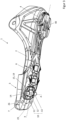
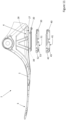
- Figure 1 is a view of a sole 1 of a ski boot showing the sole 1 mainly from the side, slightly from above and from the rear to the front.
- the sole 1 is an integrated sole 1 comprising a sole base 2, a forefoot outsole element 6, and an outsole heel support 40.
- the forefoot outsole element 6 and the heel support 40 are attached to the underside of the sole base 2.
- the outsole element 6 may be joint to the sole base 2, for example, by adhesive bond or some other type of bonding. The respective jointing may be supplemented by positive and/or non-positive locking of one or both of the elements 6 and 40 to the sole base 2.
- the sole 1, in the example embodiment the sole base 2 in combination with the forefoot outsole element 6, provides an upward facing surface on which the foot of the skier is resting during use.
- the sole base 2 may expediently be formed in one-piece of a polymer material that is reenforced with fibers and/or formed structures and/or particles. It may in particular be laminated or molded.
- the sole base 2 may have a laminate structure or contain one or more laminate layers.
- the heel support 40 may be joint to the sole base 2, for example, by adhesive bond or some other type of bonding, as mentioned earlier. In the example embodiment, however, the heel support 40 is more advantageously removably secured to the sole base 2 by means of a positive engagement and, optionally, in addition by a force-fitting engagement, without bonding.
- the sole 1 may comprise an interface 30 located in the sole heel portion 4 at the underside of sole base 2.
- Heel support 40 may removably be connected to the sole base 2 by means of a positive retaining engagement with the interface 30.
- the securement is designed such that heel support 40 can easily and rapidly be removed and exchanged against another heel support configured to match with the interface 30.
- the securement allows for non-destructive removal and replacement of heel support 40 by hand and the aid of a simple hand tool, such as a screw driver or the like, or preferably without the aid of any tool.
- the sole base 2 may be formed originally with the interface 30.
- the interface 30 may be provided as an interface structure manufactured separately from and immovably connected to the sole base 2, for example by adhesive bonding or some other type of bonding.
- Interface 30 is located between sole heel portion 4 and heel support 40. It may be joint with sole base 2 in direct contact.
- the interface 30 overall has the shape of a plate. It is relatively thin but strong and stiff enough to firmly retain the heel support 40 in the positive retaining engagement at the sole base 2.
- the ski boot may be divided into three general regions, namely, a forefoot region, a midfoot region, and a heel region.
- Sole 1 comprises correspondingly a sole forefoot portion 3, a sole midfoot portion, and a sole heel portion 4.
- Sole 1 also includes a lateral side and a medial side.
- Forefoot portion 3 corresponds with the toes and the joints connecting the metatarsals with the phalanges.
- Midfoot portion corresponds with the arch area of the foot
- heel portion 4 corresponds with rear portions of the foot, including the calcaneus bone.
- the lateral side and the medial side correspond with opposite sides of the sole 1 and the ski boot.
- the ski boot comprises an upper.
- the sole 1 and the upper enclose a boot internal space for accommodating a skier's foot.
- the upper may be formed separately and joint with the sole 1 or formed with the sole 1, for example with the sole base 2, in one piece, for example by additive or generative processes.
- a lower part of the upper is shown in the figures 7 and 8 and denoted there with reference number 9.
- the forefoot outsole element 6 is dished and comprises an upstanding portion 7 that extends upwards around the front end and along adjacent side sections of the upward facing surface of the sole 1.
- the sole base 2 comprises an upstanding portion 8 that extends upwards from the sole upward facing surface and wraps up around the back and sides in the heel portion 4.
- the upstanding portion 8 may be provided with holes 18, as illustrated, to enable an ankle cuff or part of an ankle cuff to be connected to the sole base 2 in a hinged manner.
- the upstanding portions 7 and 8 and the upper extend from the sole upward facing surface along a boot internal rim 5 that marks the outer skirt of the sole upward facing surface within the boot internal space.
- the sole upward facing surface constitutes the underside of the boot internal space whereas the upstanding portions 7 and 8 and the upper provide for the remainder of the envelope of the boot internal space.
- the upstanding portions 7 and 8 may be regarded to constitute part of the upper in so far as they limit the boot internal space to the front, the rear and to the medial and lateral sides, i. e. upstanding portions 7 and 8 border the sole upward facing surface and, hence, the skier's foot to the front, the rear, and also to the sides.
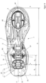
- Figure 2 is a plan view onto the sole upward facing surface.
- the sole upward facing surface formed by the integrated sole 1 and enclosed by the boot internal rim 5 extends along a longitudinal axis X of the ski boot between a virtual front axis F and a virtual rear axis R which are both orthogonal to the longitudinal axis X and tangential to a foremost end and a rearmost end of the boot internal rim 5, respectively.
- the rear axis R intersects the longitudinal axis X at a rearmost point RP of the rim 5.
- a straight connecting line BG connects a most medial point MP and a most lateral point LP both located in the sole forefoot portion 3 on the boot internal rim 5.
- CP denotes a center point located in the middle between the most medial point MP and the most lateral point LP on connecting line BG.
- the longitudinal axis X intersects the rear axis R at the rearmost point RP and the connecting line BG at the center point CP.
- the ski boot comprises a connecting structure 10 for securement to a toe piece of a ski binding of a ski for cross-country or Nordic skiing or a roller ski board.
- the connecting structure 10 defines a lateral pivot axis A below the sole forefoot portion 3 to allow for pivoting movement of the ski boot relative to the ski.
- Figure 3 is a view of the sole 1 showing its underside where the connecting structure 10 is mounted.
- the connecting structure 10 is mounted directly to the sole base 2.
- the ski boot differs from prior art ski boots which comprise connecting structures mounted to outsole elements such as the forefoot outsole element 6 and not directly to a sole base such as sole base 2.
- the forefoot outsole element 6 comprises a recess 19 in the region where the connecting structure 10 is located to allow for directly jointing the connecting structure 10 to the sole base 2.
- the connecting structure 10 is joint to the sole base 2 by non-positive locking.
- the joint connection is a screw connection, as preferred, but could instead be formed as a riveted joint or the like.
- a purely non-positive locking, in particular a pure screw connection, is the preferred joint between the connecting structure 10 and the sole base 2.
- the connecting structure 10 is formed in one piece as a cleat and may in particular be a metal cleat. It comprises an attachment base 11 with through-holes 12 for fastening elements such as screws or rivets that penetrate the attachment base 11 to fasten the connecting structure 10 to the sole base 2.
- the connecting structure 10 furthermore comprises a bearing structure 13 that protrudes downwardly from the attachment base 11 to define the pivot axis A at a vertical distance from the sole 1.
- the bearing structure 13 accommodates engaging members 14, a left and a right engaging member 14, moveably in the lateral direction parallel to the pivot axis A.
- the engaging members 14 may be formed as pins. They may be biased, for example spring-loaded, each to an outward position and can be suppressed towards one another, against the biasing or spring force.
- the ski boot is pressed towards a toe piece of the ski binding such that the engaging members 14 first yield against the biasing force and then snap forward into respective holes or deepenings of the toe piece of the ski binding thereby securing the ski boot to the toe piece of the ski binding and establishing the pivot axis A of the ski boot relative to the ski.
- the left and right engaging members 14 are movable laterally relative to the ski boot.
- the engaging members 14 may be immovable relative to the rest of the connecting structure 10.
- the toe piece of the ski binding may provide for the movability to enable a snap-in securement of connecting structure 10 to the ski binding.
- the protruding engaging members 14 could be substituted by holes or deepenings in the bearing structure 13 and the ski binding provided with corresponding engagement pins or the like that protrude laterally to engage into the holes or deepenings of the modified connecting structure 10.
- the connecting structure 10 may comprise a rigid lateral bar to define pivot axis A.
- the connecting structure 10 is mounted to the sole 1 in surface contact with a first mounting area 15 of the sole 1.
- the first connecting structure 10 covers the first mounting area 15, i.e. the first mounting area 15 is not visible.
- the first mounting area 15 is a downward facing surface of the sole 1. More specifically, it is a downward facing surface of the sole base 2.
- the sole 1 furthermore comprises a second mounting area 25 with fastening elements 26 for mounting a second connecting structure in surface contact with the second mounting area 25, as will be explained later.
- Figure 4 is a plan view onto the underside of the sole 1. As can be seen, the pivot axis A is positioned relatively far to the rear, as compared with conventional ski boots, to improve the efficiency of power transmission when pushing back on the ski during cross-country skiing.
- the pivot axis A intersects the longitudinal axis X in a mid-section between the front axis F and the center point CP.
- the longitudinal axis X extends from the rearmost point RP of the boot internal rim 5 in the forward direction through the center point CP on the connecting line BG.
- the axes F and R are parallel one to the other and orthogonal to the longitudinal axis X.
- Front axis F is tangential to the boot internal rim 5 at the foremost point of rim 5.
- Rear axis R is tangential to the boot internal rim 5 at the rearmost point RP of the rim 5.
- the pivot axis A intersects the longitudinal axis X between the front axis F and the center point CP at an axial distance d A from the front axis F and an axial distance d CP from the center point CP.
- the axial distances d A and d CP may be equal. In the example embodiment, they are only approximately the same in that the axial distance d A is slightly larger than the axial distance d CP . It is advantageous if d A > 0.7 • d CP . Better results can be achieved if d A ⁇ 0.8 • d CP . The results are best if d A ⁇ 0.9 • d CP .
- the pivot axis A should, on the other hand, not be located too far towards the rear in order not to restrict the pivoting movement of the ski unnecessarily. Good results are achieved if d A ⁇ 1.3 • d CP . More advantageously d A ⁇ 1.2 • d CP or d A ⁇ 1.1 • d CP .
- An overall axial length of the sole upward facing surface is measured in the plan view along the longitudinal axis X as the axial distance D between the front axis F and the rearmost point RP or rear axis R of the boot internal rim 5.
- the axial distance d A may advantageously be chosen such that 0.1 • D ⁇ d A ⁇ 0.2 • D.
- the pivot axis A intersects the longitudinal axis in embodiments fulfilling these two relations with an axial offset d A to the front axis F of 10 to 20% of the overall length D.
- the axial offset d A may even more preferred be equal or greater than 0.12 • D and/or it may be equal or smaller than 0.18 • D.
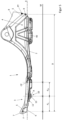
- Figure 5 shows the sole 1 in a side view and in relation to a supporting plane that may serve as a plane of measurement M.
- a ski equipped with a ski binding suitable for co-operation with the ski boot is placed on the plane of measurement M.
- the ski boot is connected to the ski by engaging the connecting structure 10 with the toe piece of the ski binding and the ski boot is pivoted towards the ski such that the sole 1 is resting on a heel piece of the ski binding if the ski binding regularly comprises a heel piece, or directly on the ski if the ski binding does not regularly comprise a heel piece.
- the sole 1 occupies a position it is supposed to occupy in relation to the plane of measurement M supporting the ski.
- the pivot axis A, the front axis F, the center point CP, the rear axis R, and the longitudinal axis X are then projected each orthogonal onto the plane of measurement M.
- the axial distances d A and d CP and D are measured along the longitudinal axis X on the plane of measurement M.
- the rear axis R of rim 5 is shown to extend axially offset forward of the rearmost point of the boot internal space.
- the rearmost point of the boot internal space is denoted PT for its correspondence to the rearmost point, the pternion, of a foot that matches the ski boot in size.
- rear axis R may extend exactly below or slightly to the rear of PT.
- Figure 6 is a plan view onto the underside of a foot.
- Figure 6 serves to explain anatomical measures helpful to understand the background of the invention.
- the foot size is measured along the longitudinal axis X as the length between a rearmost plane contacting the foot at the rearmost point of the heel, the so-called pternion PT, and a foremost plane contacting the tip of the toes.
- the two planes are parallel one to the other and orthogonal to the longitudinal axis X.
- the front axis F and the rear axis R, which are tangential to the boot internal rim 5 are shown in dotted lines.
- the front axis F intersects the longitudinal axis X at a certain, typically small distance forward of the foremost plane of contact.
- This axial offset is denoted as clearance ⁇ .
- Clearance ⁇ may measure a few millimeters and may, for example, be 3 ⁇ 2 mm.
- the rear axis R intersects the longitudinal axis X at a certain distance forward of the rearmost plane of contact but could alternatively extend in the rearmost plane of contact or slightly aft of it, as mentioned above.
- the metatarsophalangeal joints are represented by the straight line BG which is the orthogonal projection of the ball girth cross-section onto a plane supporting the foot.
- the line BG passes through the metatarsale tibiale MT and the metatarsale fibulare MF.
- Line BG also passes through a most medial point and a most lateral point of the foot.
- the longitudinal axis X extends from the pternion PT forward and through the center point CP which is located on the line BG in the middle between MP and LP.
- Pivot axis A is slightly tilted towards the longitudinal axis X, mainly to show that pivot axis A must not necessarily be exactly orthogonal to the longitudinal axis X. The deviation from a right angle is only a few degrees.
- the pivot axis A intersects the longitudinal axis X between the foremost plane of contact and the foot center point CP at an axial distance d FA from the foremost plane of contact and an axial distance d CP from the foot center point CP.
- Figure 6 may be regarded as an overlay of a foot having the foot size L and the ski boot having a corresponding boot size.
- the longitudinal axis X of the ski boot is an approximation for the foot longitudinal axis X. The same is true with respect to the connecting line BG and the center point CP of the ski boot which correspond to the ball girth line BG of the foot and the foot center point CP.
- the boot internal rim 5 ( Fig. 2 ) is a line that follows the outer contour of the foot of corresponding size with a certain outsize, i. e.
- the front axis F is located a certain although small distance forward of the foremost tip of the toes and the most medial and most lateral points MP and LP on the boot internal rim 5 are at a certain although small distance to the left and right of the corresponding points MP and LP of the foot.
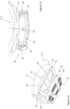
- Figures 7 and 8 are schematic illustrations showing the front part of the ski boot in a longitudinal section along the longitudinal axis X.
- Figure 7 shows an embodiment in which an upper 9 is joint with the sole 1 at an inner circumferential surface of upstanding portion 7.
- the lower part of upper 9 limits the boot internal space available for the foot in the boot forefoot region.
- the boot internal rim 5 that skirts the sole upward facing surface is accordingly defined by the sole upward facing surface in conjunction with the upper 9.
- Figure 8 shows an embodiment that is modified in that the upper 9 surrounds the upstanding portion 7, i. e. the upper 9 is joint to the sole 1 at the outer circumferential surface of the upstanding portion 7.
- upstanding portion 7 limits the boot internal space available for the foot in the boot forefoot region.
- the boot internal rim 5 that skirts the sole upward facing surface is accordingly defined by the sole upward facing surface in conjunction with the upstanding portion 7 of the sole 1, in the example embodiment, of the forefoot outsole element 6.
- Figures 7 and 8 also show the mounting of the connecting structure 10 directly on the sole base 2 which comprises the first mounting area 15 in the example embodiment.
- the forefoot outsole element 6 is spared to form the recess 19 in which the connecting structure 10 is located for directly mounting it on the sole base 2, for example, by screw connection, as preferred, or rivet joint.
- the ski boot sole 1 and the connecting structure 10 may be components of a ski boot system which provides the choice to equip a ski boot either with the connecting structure 10, as a first connecting structure, or another connecting structure, as a second connecting structure.
- the second connecting structure if mounted, defines a lateral second pivot axis for pivoting the respective ski boot about the second pivot axis relative to the second ski, wherein the second pivot axis intersects the longitudinal axis X of the ski boot, in the plan view, further forward than the pivot axis A does. Equipping the ski boot with either the first or the second connecting structure involves no or only minor modifications to the ski boot sole.
- the shape of the sole base 2, in particular, is the same for both variants.
- the upper of the boot can stay the same but may instead be designed as desired.
- a first ski boot comprising a sole 1 with the first connecting structure 10 mounted and a first upper and a second ski boot comprising a sole 1 with the second connecting structure 20 mounted and a second upper that differs from the first upper not only because of different boot sizes are both regarded as ski boots of the ski boot system according to the invention.
- the respective sole 1 must however comprise mounting areas, such as the mounting areas 15 and 25, to offer a choice between distinct connecting structures.
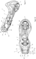
- Figures 9 and 10 show the second variant of the ski boot which differs from the first variant of which the sole 1 is illustrated in the figures 1 to 8 in that a second connecting structure 20 has replaced the first connecting structure 10.
- the second connecting structure 20 is mounted to the second mounting area 25 of the sole 1.
- the first mounting area 15 for mounting the first connecting structure 10 is no longer occupied and visible in the view of figure 9 and the plan view of figure 10 .
- the first mounting area 15 is circumscribed by an inner rim of the forefoot outsole element 6, the inner rim defining the recess 19 of the forefoot outsole element 6.
- First fastening elements 16 are arranged within the first mounting area of the sole base 2.
- the first fastening elements 16, each formed as a cavity such as a deepening or preferably as a through-hole, are indicated in figure 10 in dashed lines but not shown in figure 9 .
- the sole base 2 is provided with the fastening elements 16 at least in the first variant of the ski boot in which the first connecting structure 10 is mounted in surface contact with the first mounting area 15 and fastened by means of pins or rivets or preferably by means of screws protruding through the through-holes 12 of the first connecting structure 10 ( figures 3 and 4 ) and through or into the first fastening elements 16 of the sole base 2.
- the first fastening elements 16 are not shown in the isometric view of figure 9 not the least to demonstrate that the sole 1 does not necessarily comprise first fastening elements in the second variant.
- the sole 1, or as in the example embodiments its sole base 2 may accordingly differ between the two variants of the ski boot in that it comprises the first fastening elements 16 only in the first variant.
- the sole base 2 comprises the first fastening elements 16, for example arranged as shown, in both variants.
- the sole base 2 comprises the first fastening elements 16 also in the second variant of the ski boot, in which the second connecting structure 20 is mounted, such first fastening elements 16 are not needed or needed only to facilitate exchanging the second connecting structure 20 against the first connecting structure 10.
- the first fastening elements 16 may be sealed to prevent the ingress of moisture. Sealing can be provided by filling the respective through-hole with sealing mass.
- the ski boot system may comprise a modified forefoot outsole element to substitute the forefoot outsole element 6 of the example embodiment.
- the modified forefoot outsole element does not comprise the recess 19 and covers the not used first mounting area 15 of the sole base 2.
- the modified forefoot outsole element may comprise protrusions which protrude into the through-holes 16 to seal the same and at the same time provide for additional hold on the sole base 2.
- the ski boot system may comprise a plug-in element for sealing the fastening elements 16.
- the plug-in element comprises protrusions to be plugged into the fastening elements 16 thereby sealing the same and retaining the plug-in element on the sole base 2.
- the plug-in element may be formed to fill the recess 19 of the forefoot outsole element 6 completely or only partially.
- the sole 1 may comprise the second fastening elements 26 assigned to the second connecting structure 20 either only if the second connecting structure 20 is mounted, i.e. in the second variant, or in both variants.
- the sole 1 of the example embodiment comprises the second fastening elements 26 not only in the second variant but also in the first variant, as can be seen in the figures 3 and 4 .
- the second mounting area 25 is provided on the underside of the forefoot outsole element 6.
- the second fastening elements 26 are provided each as a through-hole in the forefoot outsole element 6.
- the forefoot outsole element 6 may comprise at least one second fastening element 26 to the left and at least one second fastening element 26 to the right of the longitudinal axis X.
- the sole base 2 may comprise second fastening elements in alignment with the second fastening elements 26 of the forefoot outsole element 6.
- the second fastening elements of the sole base 2 may be provided as cavities, such as through-holes or deepenings, arranged in alignment with the second fastening elements 26 of the forefoot outsole element 6 in order to allow a pin, screw shaft or rivet shaft to protrude through the second fastening elements 26 and into or through the corresponding cavities of the sole base 2 in order to fasten the second connecting structure 20 via the forefoot outsole element 6 to the sole base 2.
- the second connecting structure 20 may in a modification be fastened by means of the second fastening elements 26 only to the forefoot outsole element 6 and connected to the sole base 2 indirectly via the forefoot outsole element 6.
- a direct connection via the second fastening elements 26 and corresponding cavities in the sole base 2 is however preferred.
- the ski boot system may accordingly comprise a further forefoot outsole element which differs from the forefoot outsole element 6 in that it does not comprise the second fasting elements 26. It can be identical in the remainder.
- the sole base 2 comprises cavities in alignment with the second fastening elements 26 also in the first variant of the sole 1 and if the cavities are provided as through-holes these through-holes may be sealed by means of a sealing mass filling the through-holes and/or covered by the further forefoot outsole element.
- the further forefoot outsole element may comprise protrusions which protrude into the through-holes of the sole base 2 to seal the same and at the same provide for additional hold on the sole base 2.
- the second connecting structure 20 is a conventional connecting structure used already in Nordic skiing. It comprises an attachment base consisting of two sidebars 21. One of the sidebars 21 is arranged left of the longitudinal axis X and the other sidebar 21 is arranged to the right of the longitudinal axis X. The sidebars 21 protrude from the underside of the sole 1 in a direction transverse to the second pivot axis B.
- the sidebars 21 are interconnected by means of an engaging member 24 which defines the second pivot axis B and engages with a toe piece of a second ski binding when the ski boot is secured to the second ski binding.
- the engaging member 24 may be formed as a rod or bar which extends in the lateral direction between the two sidebars 21.
- the engaging member 24 may on both ends be embedded in the sidebars 21 or joint thereto in some other way in order to hold the two sidebars 21 together.
- the connecting structure 20 as a whole is thereby provided as a compact mounting unit.
- the second mounting area 25 is arranged further forward than the first mounting area 15.
- the second mounting area 25 may advantageously be arranged in its entirety forward of the first mounting area 15, with no overlap, as in the example embodiment.
- the connecting structures 10 and 20 are sufficiently short in the longitudinal direction to avoid a major axial overlap. They may be short enough to avoid any axial overlap of the two mounting areas 15 and 25. Only one of the two connecting structures 10 and 20 is mounted.
- Figure 10 shows the relationships with regard to the axial position of the first pivot axis A and the axial position of the second pivot axis B.
- the first pivot axis A measured along the longitudinal axis X, is axially offset considerably to the rear relative to the second pivot axis B.
- the second pivot axis B intersects the longitudinal axis X, as seen in the plan view, in an axial region which extends from below the tip of the skier's foot rearward below the most distal phalanx.
- the pivot axis B intersects the longitudinal axis X at an axial distance d B from the front axis F.
- the axial distance d B is smaller than 20 mm or smaller than 15 mm.
- the axial distance d B is at most 10 mm.
- the axial offset d A - d B of the pivot axes A and B is greater than 10 mm or is at least 20 mm. It may be equal or greater than 25 mm or 27 mm.
- the ski boot system may comprise a plurality of outsole heel supports, such as the outsole heel support 40 shown in the figures 1 to 5 as a first heel support and at least one further outsole heel support, for example the outsole heel support 50 shown in the figures 9 and 10 as a second heel support.
- the heel supports 40 and 50 are removable and interchangeable.
- the sole 1, here the sole base 2, and the heel supports 40 and 50 are designed accordingly.
- the heel supports 40 and 50 may be identical in all respects, so that one of the heel supports 40 and 50 may simply serve as a substitute for the other to replace the other, for example, in the event of wear. In further developments, the heel supports 40 and 50 differ from each other in at least one characteristic. In the example embodiment, the heel supports 40 and 50 differ in thickness, measured transversely to the underside of the sole base 2. A ski boot with the sole base 2 and interface 30, together with the heel supports 40 and 50, forms a ski boot system that offers the possibility of optionally mounting either the first heel support 40 or the second heel support 50.
- the sole base 2 is formed with a platform 27 arranged in the sole heel portion 4 and there forming the underside of the sole base 2.
- the platform 27 has a downward facing surface 28, for example a planar surface 28, to which the interface 30 will be attached and preferably bonded.
- the interface 30 has an upward facing surface, for example a planar surface, facing the platform 27.
- the interface 30 may comprise one or more positioning elements 39. Each respective positioning element 39 co-operates with an associated positioning counter element of the sole base 2.
- the interface 30 comprises a first and a second positioning element 39.
- the positioning elements 39 are protrusions which protrude from the upward facing surface 38 of the interface 30 towards the downward facing surface 28 of the platform 27.
- the positioning counter elements of the sole base 2 are cavities, such as through-holes or deepenings, each arranged and shaped to match with an associated one of the positioning elements 39.
- the positioning elements 39 may alternatively be provided as cavities, such as through-holes or deepenings, in the interface 30. The positioning counter elements would then be provided as protrusions which protrude from the downward facing surface 28 of the platform 27 towards the upward facing surface 38 of the interface 30.
- the platform 27 and the interface 30 both are thin, as measured in the vertical direction, to reduce any increase in height which could result from providing the interface 30.
- the platform 27 may ensure that the interface 30 is exposed from the underside of the sole base 2 or can enlarge an already existing exposure in order to make it easier to handle the heel supports 40 and 50 when mounting the respective one.
- the interface 30 may have a planar upward facing surface facing the platform 27.
- the interface 30 without the positioning elements 39 may, for example, have an overall thickness of less than 12 mm or less than 8 mm.
- the heel supports 40 and 50 each comprises an engagement portion 42 and 52, respectively, designed to positively engage with the interface 30 in a positive retaining engagement.
- the heel supports 40 and 50 may each furthermore comprise a covering 43 and 53 forming the heel tread surface 41 and 51, respectively.
- the covering 43 and the covering 53 may cover at least a part of the associated one of the engagement portions 42 and 52 in a plan view of the respective heel tread surface 41 and 51.
- the coverings 43 and 53 may differ in shape, such as the shape of the heel tread surface 41 and 51, and/or in dimension, such as vertical thickness, and/or in at least one material property, such as modulus of elasticity, hardness, and damping. In the example embodiment the coverings 43 and 53 differ in vertical thickness, as will be explained below.
- Figure 11 shows the sole base 2 without any forefoot outsole element.
- a forefoot outsole element such as the forefoot outsole element 6, can be attached and fastened to the sole base 2 by means of a positive and/or a force-fitting engagement and/or by bonding.
- a forefoot outsole element such as the forefoot outsole element 6, may furthermore be moulded to and around the sole forefoot portion 3.
- the sole 1 may do without a forefoot outsole element so that the sole forefoot portion 3 is formed by the sole base 2 alone.
- the sole base 2 may be the same for the first connecting structure 10 and the second connecting structure 20. It may include all of the fastening elements for selectively mounting either the first connecting structure 10 or the second connecting structure 20. If the number of fastening elements, such as through-holes, is to be reduced, a first sole base 2 may be provided for the first connecting structure 10 and a second sole base 2 may be provided for the second connecting structure 20, the two sole bases 2 differing only in that the first sole base 2 has no fastening elements for the second connecting structure 20 and the second sole base 2 has no fastening elements for the first connecting structure 10.
- the interface 30 may be identical in each of the variants.
- Figures 12 and 13 are views showing the sole heel portion 4 from behind.
- Fig. 12 is a view from below and Fig. 13 is a view slightly from above.
- the interface 30 is positioned and aligned for mounting to the sole base 2 but still not mounted so that the downward facing surface 28 of the platform 27 and a rear positioning counter element 29 are visible.
- the interface 30 is in the positive retaining engagement with the first heel support 40.
- the interface 30 and the heel support 40 form a slider joint in which the interface 30 guides the heel support 40 from an initial position of engagement to a use position of engagement.
- the slider joint may be a linear (prismatic) joint.
- the interface 30 may guide the heel support 40 axially, i.e. in the longitudinal direction.
- heel support 40 When heel support 40 reaches its use position it is locked in the use position by a releasable locking engagement.
- the locking engagement may be established automatically when the heel support 40 has reached its use position.
- the interface 30 and the heel support 40 may comprise a locking member and a locking counter member which engage with one another in the locking engagement. To engage automatically, at least one of these members may be forced to yield against an elastic restoring force during the sliding movement and snap into the locking engagement once the use position is reached.
- the locking engagement can be released by actuating a respective element, as for example the locking member, and moving it out of the locking engagement against the restoring force.
- Figures 12 and 13 show the heel support 40 in an intermediate position of engagement between the initial position and the use position.
- the heel support 40 slides from its initial position rearward towards the use position.
- the rearward sliding movement may be blocked by means of the releasable locking engagement and/or by means of an axial blocking element 35 of the interface 30.
- the optional blocking element 35 may, for example, protrude downward at the rear end of the interface 30.
- the interface 30 has guideways 34 that extend axially. These may be lateral guideways 34, a left guideway 34 and a right guideway 34. Guideways 34 may project freely to the sides. Heel support 40 comprises associated guided members 44 for engaging the guideways 34. These may be lateral guided members 44, a left guided member 44 for engaging the left guideway 34 and a right guided member 44 for engaging the right guideway 34. The respective guided member 44 reaches behind the associated guideway 34 thereby retaining the heel support 40 at the interface 30 and via the interface 30 at the sole base 2 in sliding engagement with the interface 30.
- the guided members 44 may protrude into an axially extending gap 33 which, in advantageous embodiments, remains between the respective guideway 34 and the underside of the sole heel portion 4, here, between the guideways 34 and the downward-facing surface 28 of the platform 27.
- Each of the guideways 34 is a retaining member and each of the guided members 44 is a retaining counter member, as mentioned above in connection with Fig. 1 .
- the gap 33 is not created until the interface 30 is connected to the sole base 2. However, Fig. 2 gives a good impression of how the respective gap 33 is determined.
- the heel support 40 may engage around the guideways 34 with its guided members 44 to create the positive retaining engagement. Heel support 40 may clamp interface 30 in the engagement around. If a gap 33 is formed between the underside of the sole heel portion 4 and the guideways 34 of interface 30, the guided members 44 of heel support 40 may alternatively or in addition be clamped in the gap 33.
- the respective clamping engagement if realized, is configured such that heel support 40 is not prevented from sliding.
- the interface 30 may taper in a step-like manner in cross-section outwardly to the left and right away from the underside of the sole heel portion 4, or in other words, the interface 30 may rise between the guideways 34 in a raised manner toward the sole heel portion 4. In the lateral direction between the guideways 34, the interface 30 may form a flat plateau and correspondingly the left and right gaps 33 towards the sole heel portion 4.
- the guided members 44 may project upwardly from the heel support 40 toward the sole heel portion 4 and may project inwardly toward each other in their upper end portion, the respective inward projection forming a retaining section.
- the respective retaining section may form an upper end of the respective guided member 44.
- the guided members 44 may be hook-shaped, for example having the shape of an angle, in particular a right angle.
- the left and right guided members 44 may each include an upstanding lateral guide section that may engage the interface 30 on the left and right sides in sliding contact with the guideways 34.
- An axially elongated lateral guide section may be provided on the left side and/or the right side of the heel support 40, from which an elongated retaining section or, more expediently, two or more axially shorter and axially spaced apart retaining sections project inwardly and engage behind the respective guideway 34 in the retaining engagement.
- the pivot axes A and B can also have a transverse, at least predominantly vertical offset to each other. More specifically, a first pivot axis plane which is parallel to the longitudinal axis X and contains the pivot axis A may have a transverse offset from a second pivot axis plane which is parallel to the longitudinal axis X and contains the pivot axis B.
- the transverse offset is measured orthogonally to one of the two planes by a point on the pivot axis, e.g. the first pivot axis A, extending in the one of the two planes, the point being laterally within the boundaries of the respective connecting structure, e.g. the first connecting structure 10.
- the first heel support 40 and the second heel support 50 are identical as far as the engagement with the interface 30 is concerned and can accordingly be interchanged. They may differ with respect to thickness, as mentioned, so that the distance between the interface 30 and the downward facing heel tread surface 41 and 51 of the respective heel support 40 and 50 can be varied. The difference in thickness of the heel supports 40 and 50 may compensate for variations with respect to the position of the pivot axes A and B relative to the sole 1.
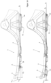
- Figure 14 the position of the first pivot axis A and the position of the second pivot axis B are compared with respect to the transverse or vertical direction.
- sole 1 is shown with the first connecting structure 10 and the associated first heel support 40 mounted.
- the sole 1 is shown with the second connecting structure 20 and the associated second heel support 50 mounted.
- the two variants, namely, sole 1, connecting structure 10 and heel support 40 in the upper part and sole 1, connecting structure 20 and heel support 50 in the lower part, are each shown in a horizontal side view which is orthogonal to the longitudinal axis X of the respective ski boot.
- Each of the two variants is shown in a position it assumes when its connecting structure and thereby the respective ski boot is secured to the associated ski binding of a ski which is laying on a planar horizontal underground. It is assumed that the longitudinal axis X is a horizontal.
- the respective ski boot rests on the heel tread surface 41 and 51 of the associated heel support 40 and 50 and can pivot about its pivot axis A and B, respectively.
- X A is a first pivot axis plane which contains the first pivot axis A and is parallel to the underground at least in the longitudinal direction.
- X B is a second pivot axis plane that contains the second pivot axis B and is parallel to the underground at least in the longitudinal direction.
- the first pivot axis A and also its pivot axis plane X A are plotted in relation to the second pivot axis B and its pivot axis plane X B .
- the comparison in the example embodiment reveals that the first pivot axis A is positioned lower than the second pivot axis B.
- the offset h AB is the transverse distance between the two pivot axis planes X A and X B .
- the first heel support 40 may be thicker than the second heel support 50 to compensate for the transverse offset h AB . This does not mean that the difference in thickness is exactly h AB since the difference in thickness may compensate for other or further variations caused by the axial offset of the pivot axes A and B. Other factors such as individual factors and preferences of the skier may also play a role.
- the sole 1 is optimized with respect to the first variant in which the pivot axis is at an advantageous rearward position.
- the optimization aims at balancing the freedom of pivoting on the one and control over the ski on the other hand.
- the first connecting structure 10 When the first connecting structure 10 is mounted, there is a point or line on the underside of the sole 1 with which the ski boot comes closest to the ski or the binding, i.e. to the vertically opposite surface, when pivoting about the first pivot axis A.
- This point or line is a critical point with respect to pivoting and is denoted by P crit in the upper part of figure 14 .
- the distance d' A is greater than 20 mm or is at least 27 mm.
- the distance d' A is greater than d A , i.e. the critical point P crit is further forward than the front axis F of the boot internal rim 5. It is advantageous if the axial offset from the front axis is small, e.g. smaller than 10 mm or smaller than 5 mm and preferably smaller than 3 mm.
- the sole 1, in the example embodiment the sole base 2 and the forefoot outsole element 6, is shaped such that the ratio h A : d' A is greater than 2:10 or is at least 2:9. A good balance is achieved if h A : d' A is 0.25 ⁇ 0.05.
- the connecting structure 10 as such accounts for a part of the distance h A .
- the distance between the pivot axis A and the upward facing contact surface of the connecting structure 10 may be used as a representative of this part.
- the contact surface of the connecting structure 10 is the surface with which the connecting structure 10 is in contact with the sole 1.
- the shape of the sole 1, such as the shape axially over the second mounting area 25, makes up the remaining part of the distance h A .
- the shape of the first connecting area 15 also contributes to this, in particular if the first mounting area 15 is inclined upwards in the direction of the tip of the ski boot away from the pivot axis plane X A , as is advantageously the case in the example embodiment.
- the distance between the pivot axis A and the upward facing contact surface of the connecting structure 10 is small, not the least in order to prevent the connecting structure 10 from protruding too much for walking without ski.
- This internal distance with respect to the connecting structure 10 may advantageously be smaller than half of the distance h A .
Landscapes
- Health & Medical Sciences (AREA)
- General Health & Medical Sciences (AREA)
- Physical Education & Sports Medicine (AREA)
- Footwear And Its Accessory, Manufacturing Method And Apparatuses (AREA)
Claims (17)
- Skischuhsystem, das Folgendes umfasst:1.1 einen Skischuh mit einer Sohle (1), die einen Sohlenvorderfußabschnitt (3) und einen Sohlenfersenabschnitt (4) aufweist, die entlang einer Längsachse (X) des Skischuhs angeordnet sind,1.2 eine erste Verbindungsstruktur (10) zur Sicherung des Skischuhs an einer ersten Skibindung eines ersten Skis und1.3 eine von der ersten Verbindungsstruktur (10) separate zweite Verbindungsstruktur (20) zur Sicherung des Skischuhs an einer zweiten Skibindung eines zweiten Skis,1.4 wobei die erste Verbindungsstruktur (10), sofern angebracht, unter dem Sohlenvorderfußabschnitt (3) eine seitliche erste Schwenkachse (A) zum Schwenken des Skischuhs um die erste Schwenkachse (A) relativ zum ersten Ski definiert, wobei die erste Schwenkachse (A) in einer Draufsicht auf die Sohle (1) gesehen die Längsachse (X) schneidet,1.5 wobei die zweite Verbindungsstruktur (20), sofern angebracht, unter dem Sohlenvorderfußabschnitt (3) eine seitliche zweite Schwenkachse (B) zum Schwenken des Skischuhs um die zweite Schwenkachse (B) relativ zum zweiten Ski definiert, wobei die zweite Schwenkachse (B) in der Draufsicht die Längsachse (X) vor der ersten Schwenkachse (A) schneidet,1.6 wobei die Sohle (1) einen nach unten weisenden ersten Anbringungsbereich (15) zur Anbringung der ersten Verbindungsstruktur (10) in Flächenberührung mit dem ersten Anbringungsbereich (15) und einen nach unten weisenden zweiten Anbringungsbereich (25) zur Anbringung der zweiten Verbindungsstruktur (20) in Flächenberührung mit dem zweiten Anbringungsbereich (25) umfasst,1.7 wobei der zweite Anbringungsbereich (25) axial weiter vorne liegt als der erste Anbringungsbereich (15),1.8 wobei nur eine aus erster Verbindungsstruktur (10) und zweiter Verbindungsstruktur (20) an der Sohle (1) angebracht ist,1.9 wobei die erste Verbindungsstruktur (10) eine erste Basis (11) mit einer Berührungsfläche zur Berührung des ersten Anbringungsbereichs (15) der Sohle (1) und ein linkes Eingriffsglied (14) und ein rechtes Eingriffsglied (14) umfasst, die die erste Schwenkachse (A) definieren und mit einem Vorderbacken der ersten Skibindung ein Schwenkgelenk bilden, wobei die erste Schwenkachse (A) die Drehachse des Schwenkgelenks ist, wobei die erste Verbindungsstruktur (10) eine Lagerstruktur (13) umfasst, die von der ersten Basis (11) in einer quer zur jeweiligen Schwenkachse weisenden Richtung vorragt und das linke Eingriffsglied (14) und das rechte Eingriffsglied (14) zum Eingriff mit dem Vorderbacken der ersten Skibindung trägt, und1.10 wobei die zweite Verbindungsstruktur (20) eine zweite Basis (21) mit einer Berührungsfläche zur Berührung des zweiten Anbringungsbereichs (25) der Sohle (1) und ein einziges Eingriffsglied (24) umfasst, das sich seitlich zwischen Seitenleisten (21) der Basis erstreckt und die zweite Schwenkachse (B) definiert und mit einem Vorderbacken der zweiten Skibindung ein Schwenkgelenk bildet, wobei die zweite Schwenkachse (B) die Drehachse des Schwenkgelenks ist.
- System nach Anspruch 1,- wobei die erste Verbindungsstruktur (10) angebracht ist und zumindest der Großteil des zweiten Anbringungsbereichs (25) vor der ersten Verbindungsstruktur (10) angeordnet ist oder- wobei die zweite Verbindungsstruktur (20) angebracht ist und zumindest der Großteil des ersten Anbringungsbereichs (15) hinter der zweiten Verbindungsstruktur (20) angeordnet ist.
- System nach einem der vorhergehenden Ansprüche, wobei das Eingriffsglied (24) der zweiten Verbindungsstruktur (20) eine Eingriffsstange (24) ist.
- System nach einem der vorhergehenden Ansprüche, wobei die erste Verbindungsstruktur (10) eine Berührungsfläche aufweist, die so geformt ist, dass sie sich an den ersten Anbringungsbereich (15) der Sohle (1) anschmiegt, und/oder die zweite Verbindungsstruktur (20) eine Berührungsfläche aufweist, die so geformt ist, dass sie sich an den zweiten Anbringungsbereich (25) der Sohle (1) anschmiegt.
- System nach einem der vorhergehenden Ansprüche, wobei die erste Verbindungsstruktur (10) so ausgelegt ist, dass sie nur die erste Schwenkachse (A) definiert, und/oder die zweite Verbindungsstruktur (20) so ausgelegt ist, dass sie nur die zweite Schwenkachse (B) definiert.
- System nach einem der vorhergehenden Ansprüche, wobei die erste Verbindungsstruktur (10) angebracht ist und die Sohle (1) ein oder mehrere zweite Befestigungselemente (26) zur Anbringung der zweiten Verbindungsstruktur (20) an der Sohle (1) umfasst, und wobei das eine oder die mehreren zweiten Befestigungselement(e) (26) axial weiter vorne angeordnet ist/sind als die erste Verbindungsstruktur (10), wobei das jeweilige zweite Befestigungselement (26) optional ein gegen Feuchtigkeitseintritt abgedichtetes Loch in der Sohle (1) ist.
- System nach einem der Ansprüche 1 bis 5, wobei die zweite Verbindungsstruktur (20) angebracht ist und die Sohle (1) ein oder mehrere erste Befestigungselemente (16) zur Anbringung der ersten Verbindungsstruktur (10) an der Sohle (1) umfasst, und wobei das eine oder die mehreren ersten Befestigungselement(e) (16) axial weiter hinten angeordnet ist/sind als die zweite Verbindungsstruktur (20), wobei das jeweilige erste Befestigungselement (16) optional ein gegen Feuchtigkeitseintritt abgedichtetes Loch in der Sohle (1) ist.
- System nach einem der vorhergehenden Ansprüche, wobei die Sohle (1) eine Sohlenbasis (2) umfasst, die den Sohlenvorderfußabschnitt (3) und den Sohlenfersenabschnitt (4) in einem Stück bildet.
- System nach dem vorhergehenden Anspruch, wobei die Sohle (1) ein Vorderfußlaufsohlenelement (6) umfasst, das an der Sohlenbasis (2) befestigt ist und zumindest teilweise die Unterseite des Sohlenvorderfußabschnitts (3) der Sohlenbasis (2) bedeckt.
- System nach dem vorhergehenden Anspruch, wobei das
Vorderfußlaufsohlenelement (6) ein oder mehrere Durchgangslöcher (26) umfasst und die Sohlenbasis (2) eine oder mehrere Ausnehmungen wie etwa ein oder mehrere Durchgangslöcher oder eine oder mehrere Vertiefungen umfasst, die mit dem einen oder den mehreren Durchgangslöchern (26) des Vorderfußlaufsohlenelements (6) fluchten, damit der Schaft einer Schraube oder einer Niete oder eines Stifts durch das jeweilige Durchgangsloch (26) des Vorderfußlaufsohlenelements (6) hindurch und durch die entsprechende Ausnehmung der Sohlenbasis (2) hindurch oder in diese hineinragen kann, um die zweite Verbindungsstruktur (20) an der Sohle (1) anzubringen. - System nach einem der drei unmittelbar vorhergehenden Ansprüche,- wobei die Sohlenbasis (2) den ersten Anbringungsbereich (15) bildet und die erste Verbindungsstruktur (10), sofern angebracht, direkt an der Sohlenbasis (2) angebracht ist und/oder- wobei das Vorderfußlaufsohlenelement (6) nach Anspruch 9 den zweiten Anbringungsbereich (25) bildet und die zweite Verbindungsstruktur (20), sofern angebracht, an dem Vorderfußlaufsohlenelement (6) angebracht ist.
- System nach einem der vorhergehenden Ansprüche in Kombination mit Anspruch 8, das Folgendes umfasst:- eine Schnittstelle (30), die an der Sohlenbasis (2) befestigt ist oder von dieser gebildet wird und in oder unter dem Sohlenfersenabschnitt (4) der Sohlenbasis (2) angeordnet ist,- eine erste Fersenstütze (40) und- eine zweite Fersenstütze (50),wobei die Schnittstelle (30), die erste Fersenstütze (40) und die zweite Fersenstütze (50) so ausgelegt sind, dass jede der Fersenstützen (40, 50) über die Schnittstelle (30), vorzugsweise durch einen formschlüssigen Halteeingriff mit der Schnittstelle (30), lösbar mit der Sohlenbasis (2) verbindbar ist und gegen die andere austauschbar ist.
- System nach dem vorhergehenden Anspruch, wobei die erste Fersenstütze (40) und die zweite Fersenstütze (50) jeweils für einen formschlüssigen Halteeingriff mit der Schnittstelle (30) ausgelegt sind, wobei die jeweilige Fersenstütze (40, 50) im Halteeingriff relativ zur Schnittstelle (30) zwischen einer Ausgangsposition und einer Gebrauchsposition bewegbar ist, wobei die jeweilige Fersenstütze (40, 50) optional durch einen lösbaren Rasteingriff der jeweiligen Fersenstütze (40, 50) mit der Schnittstelle (30) in der Gebrauchsposition arretiert ist.
- System nach einem der vorhergehenden Ansprüche, wobei die zweite Schwenkachse (B) in der Draufsicht mit einem axialen Versatz (dA - dB) zu der ersten Schwenkachse (A) die Längsachse (X) schneidet, wobei der axiale Versatz ausreichend groß ist, damit die zweite Verbindungsstruktur (20) an der Sohle (1) axial vor der ersten Verbindungsstruktur (10) bei noch angebrachter erster Verbindungsstruktur (10) angebracht werden kann.
- System nach einem der vorhergehenden Ansprüche,15.1 wobei der Skischuh ein Oberteil (19) umfasst, wobei die Sohle (1) und das Oberteil (19) einen Schuhinnenraum zur Aufnahme des Fußes eines Skifahrers umschließen,15.2 wobei die Sohle (1) optional einen aufrechten Sohlenabschnitt (7, 8) umfasst,15.3 wobei sich das Oberteil (19) und/oder der aufrechte Sohlenabschnitt (7, 8), sofern vorhanden, von einer nach oben weisenden Fläche der Sohle (1) entlang eines Schuhinnenrandes (5) nach oben erstreckt/erstrecken, der innerhalb des Schuhinnenraumes an die nach oben weisende Fläche der Sohle (1) angrenzt,15.4 wobei sich die Längsachse (X) in der Draufsicht auf die Sohle (1) gesehen von einem hintersten Punkt (RP) des Schuhinnenrandes (5) durch einen zentralen Bereich des Sohlenvorderfußabschnitts (3) hindurch erstreckt,15.5 wobei die erste Schwenkachse (A) in der Draufsicht auf die Sohle (1) gesehen in einem ersten axialen Abstand (dA) hinter einer Vorderachse (F) der Sohle (1) die Längsachse (X) schneidet, wobei die Vorderachse (F) orthogonal zur Längsachse (X) und tangential zu einem vordersten Ende des Schuhinnenrandes (5) steht,15.6 wobei der erste axiale Abstand (dA) größer als 20 mm oder größer als 30 mm und kleiner als 70 mm oder kleiner als 55 mm ist.
- System nach dem vorhergehenden Anspruch, wobei die Längsachse (X) in der Draufsicht einen Mittelpunkt (CP) durchläuft, der an einer Verbindungsgeraden (BG) angeordnet ist, die im Sohlenvorderfußabschnitt (3) einen medialsten Punkt (MP) und einen lateralsten Punkt (LP) des Schuhinnenrandes (5) verbindet, wobei entlang der Verbindungsgeraden (BG) der Mittelpunkt (CP) äquidistant zum medialsten Punkt (MP) und zum lateralsten Punkt (LP) ist, und wobei die Schwenkachse (A) in der Draufsicht die Längsachse (X) vor dem Mittelpunkt (CP) schneidet.
- System nach einem der vorhergehenden Ansprüche,- wobei die erste Verbindungsstruktur (10) wird angebracht und der Skischuh an der ersten Skibindung des auf einem ebenen horizontalen Untergrund liegenden ersten Skis gesichert wird, wobei der Skischuh um die erste Schwenkachse (A) schwenkbar ist und auf einer Fersenberührungsfläche der ersten Skibindung des ersten Skis aufliegt,- wobei sich in einer zur Längsachse (X) orthogonalen, horizontalen Seitenansicht ein Freiraum zwischen der Unterseite der Sohle (1) und einer Schwenkachsebene (XA) erstreckt, die die erste Schwenkachse (A) enthält und zumindest in Längsrichtung (X) parallel zum Untergrund ist,- wobei sich der Freiraum von der ersten Schwenkachse (A) nach vorne bis zum vordersten Ende des Skischuhs erstreckt,- wobei die Sohle (1) einen kritischen Punkt (Pkrit) umfasst, der beim Schwenken des Skischuhs um die erste Schwenkachse (A) dem Untergrund am nächsten kommt,- wobei der kritische Punkt (PA) mit einen vertikalen Abstand (hA) von der Schwenkachsebene (XA) beabstandet ist und seine vertikale Projektion auf die Schwenkachsebene (XA) mit einem horizontalen Abstand (d'A) von der Schwenkachse (A) beabstandet ist, der größer als 20 mm oder größer als 30 mm ist, wobei beide Abstände in der Seitenansicht gemessen werden,- wobei das Verhältnis hA : d'A größer als 2 : 10 ist oder mindestens 2 : 9 beträgt.
Priority Applications (1)
| Application Number | Priority Date | Filing Date | Title |
|---|---|---|---|
| SI202130310T SI3935985T1 (sl) | 2020-07-09 | 2021-04-01 | Sistem smučarskih čevljev |
Applications Claiming Priority (1)
| Application Number | Priority Date | Filing Date | Title |
|---|---|---|---|
| EP20185060.9A EP3935984B1 (de) | 2020-07-09 | 2020-07-09 | Skistiefel mit bindungsstruktur für schwenkbewegung |
Publications (2)
| Publication Number | Publication Date |
|---|---|
| EP3935985A1 EP3935985A1 (de) | 2022-01-12 |
| EP3935985B1 true EP3935985B1 (de) | 2025-03-12 |
Family
ID=71575070
Family Applications (2)
| Application Number | Title | Priority Date | Filing Date |
|---|---|---|---|
| EP20185060.9A Active EP3935984B1 (de) | 2020-07-09 | 2020-07-09 | Skistiefel mit bindungsstruktur für schwenkbewegung |
| EP21166660.7A Active EP3935985B1 (de) | 2020-07-09 | 2021-04-01 | Skischuhsystem |
Family Applications Before (1)
| Application Number | Title | Priority Date | Filing Date |
|---|---|---|---|
| EP20185060.9A Active EP3935984B1 (de) | 2020-07-09 | 2020-07-09 | Skistiefel mit bindungsstruktur für schwenkbewegung |
Country Status (2)
| Country | Link |
|---|---|
| EP (2) | EP3935984B1 (de) |
| SI (2) | SI3935984T1 (de) |
Families Citing this family (2)
| Publication number | Priority date | Publication date | Assignee | Title |
|---|---|---|---|---|
| NO348548B1 (no) * | 2022-09-29 | 2025-03-10 | Rottefella As | Skisko med myk tupp |
| FR3151968B1 (fr) | 2023-08-09 | 2026-01-02 | Salomon Sas | Chaussure de sport destinée à être connectée à un engin de sport |
Family Cites Families (19)
| Publication number | Priority date | Publication date | Assignee | Title |
|---|---|---|---|---|
| DE3915531A1 (de) | 1988-07-13 | 1990-01-18 | Salomon Sa | Langlaufskibindung |
| FR2697140B1 (fr) * | 1992-10-27 | 1994-12-02 | Rossignol Sa | Chaussure de ski de fond. |
| FR2770096B1 (fr) * | 1997-10-29 | 1999-12-17 | Salomon Sa | Semelle de chaussure de sport |
| FR2738157B1 (fr) | 1995-09-06 | 1997-10-17 | Salomon Sa | Dispositif de fixation automatique |
| FR2741543A1 (fr) | 1995-11-27 | 1997-05-30 | Bibollet Jean Claude | Fixations pour ski de fond |
| FR2819690B1 (fr) | 2001-01-22 | 2003-04-11 | Tsl Sport Equipment | Chaussure pour raquette a neige avec son insert |
| AT411018B (de) | 2001-04-11 | 2003-09-25 | Fischer Gmbh | Skibindung für langlauf- und tourenski |
| FI114615B (fi) | 2002-02-01 | 2004-11-30 | M X Sport Oy | Sovitelma hiihtokengän kiinnittämiseksi sukseen |
| EP1669113A1 (de) * | 2004-12-07 | 2006-06-14 | Mikael Östberg | Skibindung |
| WO2007058719A2 (en) * | 2005-10-07 | 2007-05-24 | Ekberg Lane A | Pivoting footwear systems and, configurable traction systems |
| FR2899443B1 (fr) * | 2006-04-07 | 2008-07-04 | Salomon Sa | Semelle de chaussure de ski de fond comportant des moyens perfectionnes d'ancrage d'un moyen de liaison et chaussure munie d'une telle semelle |
| US7444769B2 (en) * | 2006-11-03 | 2008-11-04 | Black Diamond Equipment, Ltd. | Boot binding interface system |
| FR2955466B1 (fr) * | 2010-01-25 | 2012-04-20 | Salomon Sas | Chaussure a semelage ameliore |
| FR2968898B1 (fr) | 2010-12-15 | 2013-07-26 | Salomon Sas | Chaussure de sport |
| US8960711B2 (en) | 2011-12-09 | 2015-02-24 | K-2 Corporation | Ski boot |
| NO334595B1 (no) * | 2012-10-08 | 2014-04-14 | Rottefella As | Såle med flyttbart innfestingspunkt |
| US9326563B2 (en) | 2012-10-26 | 2016-05-03 | K-2 Corporation | Base for a ski boot and ski boot incorporating such a base |
| US20140151981A1 (en) * | 2012-11-30 | 2014-06-05 | Salomon S.A.S. | Sports footwear with adjustable bending |
| FR2998764B1 (fr) | 2012-11-30 | 2015-06-19 | Salomon Sas | Chaussure de sport adaptable |
-
2020
- 2020-07-09 SI SI202030287T patent/SI3935984T1/sl unknown
- 2020-07-09 EP EP20185060.9A patent/EP3935984B1/de active Active
-
2021
- 2021-04-01 SI SI202130310T patent/SI3935985T1/sl unknown
- 2021-04-01 EP EP21166660.7A patent/EP3935985B1/de active Active
Also Published As
| Publication number | Publication date |
|---|---|
| EP3935984A1 (de) | 2022-01-12 |
| SI3935985T1 (sl) | 2025-07-31 |
| SI3935984T1 (sl) | 2023-12-29 |
| EP3935984B1 (de) | 2023-09-06 |
| EP3935985A1 (de) | 2022-01-12 |
Similar Documents
| Publication | Publication Date | Title |
|---|---|---|
| US7850194B2 (en) | Footbed for gliding board binding | |
| CA2829434C (en) | Base for a ski boot and ski boot incorporating such a base | |
| US4351120A (en) | Removable traction surfaces for footwear | |
| EP1254611B1 (de) | Steigeisen, Bergschuh und Befestigungsvorrichtung | |
| CA2184143C (en) | Method and apparatus for interfacing a snowboard boot to a binding | |
| CA2829437C (en) | Base for a ski boot and ski boot incorporating such a base | |
| US7828303B2 (en) | Gliding board assembly and a device for retaining an article of footwear on the board | |
| US20010018805A1 (en) | Sole-support assembly for a boot | |
| US6371494B1 (en) | Sports boot with variable rigidity | |
| US7444769B2 (en) | Boot binding interface system | |
| JPH0722082Y2 (ja) | スキー靴 | |
| EP3935985B1 (de) | Skischuhsystem | |
| EP1015080A1 (de) | Verbesserte skischuhbindung für snowboards | |
| EP0570048B1 (de) | Bio-mechanischer Schischuh | |
| WO1998001051A1 (en) | Grinding apparatus and associated footwear | |
| EP4066670A1 (de) | Skischuh mit fersenstütze | |
| US6845574B2 (en) | Boot for ski or in-line roller skate | |
| EP0572862A1 (de) | Sportschuh | |
| CA1076348A (en) | Inner boot for a ski boot | |
| CA2307942A1 (en) | Boot binding system for a snowboard |
Legal Events
| Date | Code | Title | Description |
|---|---|---|---|
| PUAI | Public reference made under article 153(3) epc to a published international application that has entered the european phase |
Free format text: ORIGINAL CODE: 0009012 |
|
| STAA | Information on the status of an ep patent application or granted ep patent |
Free format text: STATUS: THE APPLICATION HAS BEEN PUBLISHED |
|
| AK | Designated contracting states |
Kind code of ref document: A1 Designated state(s): AL AT BE BG CH CY CZ DE DK EE ES FI FR GB GR HR HU IE IS IT LI LT LU LV MC MK MT NL NO PL PT RO RS SE SI SK SM TR |
|
| B565 | Issuance of search results under rule 164(2) epc |
Effective date: 20210825 |
|
| STAA | Information on the status of an ep patent application or granted ep patent |
Free format text: STATUS: REQUEST FOR EXAMINATION WAS MADE |
|
| 17P | Request for examination filed |
Effective date: 20220707 |
|
| RBV | Designated contracting states (corrected) |
Designated state(s): AL AT BE BG CH CY CZ DE DK EE ES FI FR GB GR HR HU IE IS IT LI LT LU LV MC MK MT NL NO PL PT RO RS SE SI SK SM TR |
|
| STAA | Information on the status of an ep patent application or granted ep patent |
Free format text: STATUS: EXAMINATION IS IN PROGRESS |
|
| 17Q | First examination report despatched |
Effective date: 20221011 |
|
| GRAP | Despatch of communication of intention to grant a patent |
Free format text: ORIGINAL CODE: EPIDOSNIGR1 |
|
| STAA | Information on the status of an ep patent application or granted ep patent |
Free format text: STATUS: GRANT OF PATENT IS INTENDED |
|
| INTG | Intention to grant announced |
Effective date: 20240705 |
|
| GRAJ | Information related to disapproval of communication of intention to grant by the applicant or resumption of examination proceedings by the epo deleted |
Free format text: ORIGINAL CODE: EPIDOSDIGR1 |
|
| STAA | Information on the status of an ep patent application or granted ep patent |
Free format text: STATUS: EXAMINATION IS IN PROGRESS |
|
| GRAP | Despatch of communication of intention to grant a patent |
Free format text: ORIGINAL CODE: EPIDOSNIGR1 |
|
| STAA | Information on the status of an ep patent application or granted ep patent |
Free format text: STATUS: GRANT OF PATENT IS INTENDED |
|
| INTC | Intention to grant announced (deleted) | ||
| INTG | Intention to grant announced |
Effective date: 20241112 |
|
| P01 | Opt-out of the competence of the unified patent court (upc) registered |
Free format text: CASE NUMBER: APP_60389/2024 Effective date: 20241108 |
|
| GRAS | Grant fee paid |
Free format text: ORIGINAL CODE: EPIDOSNIGR3 |
|
| GRAA | (expected) grant |
Free format text: ORIGINAL CODE: 0009210 |
|
| STAA | Information on the status of an ep patent application or granted ep patent |
Free format text: STATUS: THE PATENT HAS BEEN GRANTED |
|
| AK | Designated contracting states |
Kind code of ref document: B1 Designated state(s): AL AT BE BG CH CY CZ DE DK EE ES FI FR GB GR HR HU IE IS IT LI LT LU LV MC MK MT NL NO PL PT RO RS SE SI SK SM TR |
|
| REG | Reference to a national code |
Ref country code: GB Ref legal event code: FG4D |
|
| REG | Reference to a national code |
Ref country code: CH Ref legal event code: EP |
|
| REG | Reference to a national code |
Ref country code: DE Ref legal event code: R096 Ref document number: 602021027377 Country of ref document: DE |
|
| REG | Reference to a national code |
Ref country code: IE Ref legal event code: FG4D |
|
| PG25 | Lapsed in a contracting state [announced via postgrant information from national office to epo] |
Ref country code: RS Free format text: LAPSE BECAUSE OF FAILURE TO SUBMIT A TRANSLATION OF THE DESCRIPTION OR TO PAY THE FEE WITHIN THE PRESCRIBED TIME-LIMIT Effective date: 20250612 |
|
| PG25 | Lapsed in a contracting state [announced via postgrant information from national office to epo] |
Ref country code: FI Free format text: LAPSE BECAUSE OF FAILURE TO SUBMIT A TRANSLATION OF THE DESCRIPTION OR TO PAY THE FEE WITHIN THE PRESCRIBED TIME-LIMIT Effective date: 20250312 |
|
| PG25 | Lapsed in a contracting state [announced via postgrant information from national office to epo] |
Ref country code: ES Free format text: LAPSE BECAUSE OF FAILURE TO SUBMIT A TRANSLATION OF THE DESCRIPTION OR TO PAY THE FEE WITHIN THE PRESCRIBED TIME-LIMIT Effective date: 20250312 |
|
| REG | Reference to a national code |
Ref country code: LT Ref legal event code: MG9D |
|
| PGFP | Annual fee paid to national office [announced via postgrant information from national office to epo] |
Ref country code: NO Payment date: 20250429 Year of fee payment: 5 |
|
| PG25 | Lapsed in a contracting state [announced via postgrant information from national office to epo] |
Ref country code: HR Free format text: LAPSE BECAUSE OF FAILURE TO SUBMIT A TRANSLATION OF THE DESCRIPTION OR TO PAY THE FEE WITHIN THE PRESCRIBED TIME-LIMIT Effective date: 20250312 |
|
| REG | Reference to a national code |
Ref country code: NL Ref legal event code: MP Effective date: 20250312 |
|
| PG25 | Lapsed in a contracting state [announced via postgrant information from national office to epo] |
Ref country code: LV Free format text: LAPSE BECAUSE OF FAILURE TO SUBMIT A TRANSLATION OF THE DESCRIPTION OR TO PAY THE FEE WITHIN THE PRESCRIBED TIME-LIMIT Effective date: 20250312 |
|
| PGFP | Annual fee paid to national office [announced via postgrant information from national office to epo] |
Ref country code: FR Payment date: 20250425 Year of fee payment: 5 |
|
| PG25 | Lapsed in a contracting state [announced via postgrant information from national office to epo] |
Ref country code: GR Free format text: LAPSE BECAUSE OF FAILURE TO SUBMIT A TRANSLATION OF THE DESCRIPTION OR TO PAY THE FEE WITHIN THE PRESCRIBED TIME-LIMIT Effective date: 20250613 Ref country code: BG Free format text: LAPSE BECAUSE OF FAILURE TO SUBMIT A TRANSLATION OF THE DESCRIPTION OR TO PAY THE FEE WITHIN THE PRESCRIBED TIME-LIMIT Effective date: 20250312 |
|
| PGFP | Annual fee paid to national office [announced via postgrant information from national office to epo] |
Ref country code: AT Payment date: 20250721 Year of fee payment: 5 |
|
| PGFP | Annual fee paid to national office [announced via postgrant information from national office to epo] |
Ref country code: SI Payment date: 20250331 Year of fee payment: 5 |
|
| PG25 | Lapsed in a contracting state [announced via postgrant information from national office to epo] |
Ref country code: NL Free format text: LAPSE BECAUSE OF FAILURE TO SUBMIT A TRANSLATION OF THE DESCRIPTION OR TO PAY THE FEE WITHIN THE PRESCRIBED TIME-LIMIT Effective date: 20250312 |
|
| PG25 | Lapsed in a contracting state [announced via postgrant information from national office to epo] |
Ref country code: SE Free format text: LAPSE BECAUSE OF FAILURE TO SUBMIT A TRANSLATION OF THE DESCRIPTION OR TO PAY THE FEE WITHIN THE PRESCRIBED TIME-LIMIT Effective date: 20250312 |
|
| PG25 | Lapsed in a contracting state [announced via postgrant information from national office to epo] |
Ref country code: SM Free format text: LAPSE BECAUSE OF FAILURE TO SUBMIT A TRANSLATION OF THE DESCRIPTION OR TO PAY THE FEE WITHIN THE PRESCRIBED TIME-LIMIT Effective date: 20250312 |
|
| PG25 | Lapsed in a contracting state [announced via postgrant information from national office to epo] |
Ref country code: PT Free format text: LAPSE BECAUSE OF FAILURE TO SUBMIT A TRANSLATION OF THE DESCRIPTION OR TO PAY THE FEE WITHIN THE PRESCRIBED TIME-LIMIT Effective date: 20250714 |
|
| PG25 | Lapsed in a contracting state [announced via postgrant information from national office to epo] |
Ref country code: IT Free format text: LAPSE BECAUSE OF FAILURE TO SUBMIT A TRANSLATION OF THE DESCRIPTION OR TO PAY THE FEE WITHIN THE PRESCRIBED TIME-LIMIT Effective date: 20250312 Ref country code: PL Free format text: LAPSE BECAUSE OF FAILURE TO SUBMIT A TRANSLATION OF THE DESCRIPTION OR TO PAY THE FEE WITHIN THE PRESCRIBED TIME-LIMIT Effective date: 20250312 |
|
| PG25 | Lapsed in a contracting state [announced via postgrant information from national office to epo] |
Ref country code: EE Free format text: LAPSE BECAUSE OF FAILURE TO SUBMIT A TRANSLATION OF THE DESCRIPTION OR TO PAY THE FEE WITHIN THE PRESCRIBED TIME-LIMIT Effective date: 20250312 Ref country code: CZ Free format text: LAPSE BECAUSE OF FAILURE TO SUBMIT A TRANSLATION OF THE DESCRIPTION OR TO PAY THE FEE WITHIN THE PRESCRIBED TIME-LIMIT Effective date: 20250312 |
|
| PG25 | Lapsed in a contracting state [announced via postgrant information from national office to epo] |
Ref country code: RO Free format text: LAPSE BECAUSE OF FAILURE TO SUBMIT A TRANSLATION OF THE DESCRIPTION OR TO PAY THE FEE WITHIN THE PRESCRIBED TIME-LIMIT Effective date: 20250312 |
|
| PG25 | Lapsed in a contracting state [announced via postgrant information from national office to epo] |
Ref country code: SK Free format text: LAPSE BECAUSE OF FAILURE TO SUBMIT A TRANSLATION OF THE DESCRIPTION OR TO PAY THE FEE WITHIN THE PRESCRIBED TIME-LIMIT Effective date: 20250312 |
|
| PG25 | Lapsed in a contracting state [announced via postgrant information from national office to epo] |
Ref country code: IS Free format text: LAPSE BECAUSE OF FAILURE TO SUBMIT A TRANSLATION OF THE DESCRIPTION OR TO PAY THE FEE WITHIN THE PRESCRIBED TIME-LIMIT Effective date: 20250712 |
|
| REG | Reference to a national code |
Ref country code: DE Ref legal event code: R119 Ref document number: 602021027377 Country of ref document: DE |
|
| REG | Reference to a national code |
Ref country code: CH Ref legal event code: H13 Free format text: ST27 STATUS EVENT CODE: U-0-0-H10-H13 (AS PROVIDED BY THE NATIONAL OFFICE) Effective date: 20251125 |
|
| PG25 | Lapsed in a contracting state [announced via postgrant information from national office to epo] |
Ref country code: LU Free format text: LAPSE BECAUSE OF NON-PAYMENT OF DUE FEES Effective date: 20250401 |
|
| PG25 | Lapsed in a contracting state [announced via postgrant information from national office to epo] |
Ref country code: MC Free format text: LAPSE BECAUSE OF FAILURE TO SUBMIT A TRANSLATION OF THE DESCRIPTION OR TO PAY THE FEE WITHIN THE PRESCRIBED TIME-LIMIT Effective date: 20250312 |
|
| REG | Reference to a national code |
Ref country code: BE Ref legal event code: MM Effective date: 20250430 |
|
| PG25 | Lapsed in a contracting state [announced via postgrant information from national office to epo] |
Ref country code: DE Free format text: LAPSE BECAUSE OF NON-PAYMENT OF DUE FEES Effective date: 20251104 |
|
| PG25 | Lapsed in a contracting state [announced via postgrant information from national office to epo] |
Ref country code: DK Free format text: LAPSE BECAUSE OF FAILURE TO SUBMIT A TRANSLATION OF THE DESCRIPTION OR TO PAY THE FEE WITHIN THE PRESCRIBED TIME-LIMIT Effective date: 20250312 |
|
| PG25 | Lapsed in a contracting state [announced via postgrant information from national office to epo] |
Ref country code: BE Free format text: LAPSE BECAUSE OF NON-PAYMENT OF DUE FEES Effective date: 20250430 |
|
| PLBE | No opposition filed within time limit |
Free format text: ORIGINAL CODE: 0009261 |
|
| STAA | Information on the status of an ep patent application or granted ep patent |
Free format text: STATUS: NO OPPOSITION FILED WITHIN TIME LIMIT |
|
| PG25 | Lapsed in a contracting state [announced via postgrant information from national office to epo] |
Ref country code: CH Free format text: LAPSE BECAUSE OF NON-PAYMENT OF DUE FEES Effective date: 20250430 |
|
| REG | Reference to a national code |
Ref country code: CH Ref legal event code: L10 Free format text: ST27 STATUS EVENT CODE: U-0-0-L10-L00 (AS PROVIDED BY THE NATIONAL OFFICE) Effective date: 20260121 |
|
| 26N | No opposition filed |
Effective date: 20251215 |
|
| GBPC | Gb: european patent ceased through non-payment of renewal fee |
Effective date: 20250612 |