EP3935337B1 - Aktive vorrichtung zur vollständigen unterdrückung des rückstosses einer feuerwaffe bezüglich der laufachse - Google Patents
Aktive vorrichtung zur vollständigen unterdrückung des rückstosses einer feuerwaffe bezüglich der laufachse Download PDFInfo
- Publication number
- EP3935337B1 EP3935337B1 EP20725805.4A EP20725805A EP3935337B1 EP 3935337 B1 EP3935337 B1 EP 3935337B1 EP 20725805 A EP20725805 A EP 20725805A EP 3935337 B1 EP3935337 B1 EP 3935337B1
- Authority
- EP
- European Patent Office
- Prior art keywords
- fluid
- discharge
- weapon
- tank
- pressure
- Prior art date
- Legal status (The legal status is an assumption and is not a legal conclusion. Google has not performed a legal analysis and makes no representation as to the accuracy of the status listed.)
- Active
Links
Images


Classifications
-
- F—MECHANICAL ENGINEERING; LIGHTING; HEATING; WEAPONS; BLASTING
- F41—WEAPONS
- F41A—FUNCTIONAL FEATURES OR DETAILS COMMON TO BOTH SMALLARMS AND ORDNANCE, e.g. CANNONS; MOUNTINGS FOR SMALLARMS OR ORDNANCE
- F41A1/00—Missile propulsion characterised by the use of explosive or combustible propellant charges
- F41A1/08—Recoilless guns, i.e. guns having propulsion means producing no recoil
Definitions
- the invention belongs to the field of devices for assisting in firing a firearm.
- the invention belongs to the field of devices for assisting in firing a firearm, by absorbing the recoil of the weapon.
- the invention belongs to the field of devices for assisting in firing a firearm, by actively absorbing the recoil of the weapon.
- Firing a projectile from a firearm generates a momentum that is generally applied to the breech in the direction opposite to the motion of the projectile.
- the recoil force can be more or less significant depending on the time span during which the support will dissipate the energy associated with the recoil.
- Recoilless barrels are for example known today, these barrels have tubes that guide a self-propelled projectile. Starting from a use for standard ammunition, they gradually found their use against anti-tank weapons. The first were used during the First World War (eg Davis gun). The combustion gases are used to push the shell into the barrel by relying on the air at the rear of the barrel.
- First World War eg Davis gun
- the present invention proposes a radical solution to this problem: Total inhibition in the axis of the barrel of the recoil transmitted to the support by means of a device fixed to the rear of a weapon.
- the invention relates to a device for inhibiting the recoil of firearms, and to be effective, the device must be perfectly aligned with the axis of the projectile/breech.
- the invention relates to a device for inhibiting recoil in the axis of the barrel intended to be implemented with a firearm according to claim 1.
- the ultimate goal is that the fluid expelled at a certain velocity through the discharge zone equalizes in momentum that of the projectile and the burnt gases.
- the shape of the discharge zone, the pressure and volume of the fluid in the reservoir can be optimized for each type of firearm ranging from small caliber to artillery gun.
- the primary mechanism comprises a needle valve having a head regulating the discharge flow of fluid by sealing/unsealing the neck of the discharge zone, and the pressure rise in the pipeline causes the needle valve to move when the pressure rise is greater than the internal pressure of the tank, thereby allowing the discharge of the pressurized fluid contained in said tank.
- the system transmitting the discharge command relies on the recoil of the breech relative to the mount or relies on the detection of gas or combustion gas pressure of the weapon to transmit the discharge command to the primary system to discharge the fluid, said discharge command being transmitted by means of a mechanism selected from an electrical, mechanical, electromechanical or hydraulic mechanism.
- the device uses the movement of the breech relative to the frame to actuate the valve of the primary mechanism by means of an electromechanical mechanism thereby enabling the discharge of fluid.
- the present invention provides a weapon recoil inhibiting device for attachment to the rear of a weapon.
- the device is highly advantageous in that it can be adapted for use with various types of commercially available weapons.
- said device is adapted to perform a fluid discharge generating a momentum counteracting the momentum generated by the projectile and the burnt gas when said weapon is fired.
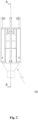
- the present invention relates to a device ( Fig. 1 ) for inhibiting the recoil in the axis of the barrel intended to be implemented with a firearm, said device carrying out a discharge of pressurized fluid in a direction opposite to the axis of the barrel to absorb the recoil of the weapon.
- the device of the invention is particular in that it is an independent part of the weapon which is fixed to the rear of the latter and comprises specific and exclusive elements for the operation of said device.
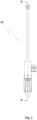
- the device illustrated in Figures 1-6 corresponds to an embodiment in which the system transmitting the discharge order comprises a pipe comprising an incompressible fluid capable of connecting with a gas borrow pipe of the weapon when the device is fixed with said weapon. Said pipe opens onto the primary mechanism ensuring the sealing and discharge of the tank (13) and transmits the discharge order by means of a pressure increase in said pipe, as will be detailed below.
- This embodiment is given as an example and the device of the invention can use other mechanisms to transmit the discharge order to the primary mechanism (15) without departing from the scope of the invention.
- the reservoir (13) contains a pressurized fluid which in this embodiment may be air.
- This reservoir is supplied by an external system via a secondary filling mechanism (12).
- the filling may be provided permanently or synchronized with the mechanism of the firearm.
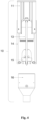
- the burning chemical element contained in the cartridge case (84) when the firearm (80) is fired, the burning chemical element contained in the cartridge case (84) generates hot gases that push the projectile (82) forward.
- the piston (85) is moved by the pressure transmitting the pressure wave generated by the burning gases to the gas borrow pipe (14).
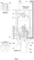
- the fluid (14a) of this pipe will, via the pipe (16f) and (15c) accumulate in the space (14c), between the support (15a) and the tail of the needle (15g) (fig. 7).
- This pressure increase greater than the internal pressure of the tank will move the needle (15d).
- the movement of the latter will break the seal between the head of the needle (15f) and the rear of the neck (16b) (fig. 8), which will release the pressurized fluid into the expansion zone (16c).
- the neck (16b) and the expansion zone (16c) take the form of a Laval nozzle.
- This neck (16b) imposes a sonic limit on the outgoing fluid and consequently the mass flow rate of the device (10).
- the expansion zone (16c) of divergent shape allows the expansion of this fluid by reducing pressure and increasing speed.
- the end diameter of this zone (16d) is said to be "adapted" to allow maximum use of the energy contained in the pressurized fluid by ensuring an outlet pressure of the fluid equivalent to the pressure of the external environment.
- the nozzle has a physical phenomenon of its own where the velocity of the fluid in its throat cannot have a speed greater than the speed of sound in the throat.
- the flow can be subsonic, sonic, but not supersonic.
- the pressure and temperature of the tank define the density of the fluid in the neck.
- the throat section, the temperature and the pressure in the tank determine the mass flow rate obtained through the throat.
- the fluid in this throat is not fully expanded and will gradually do so in the divergent until its pressure is equal to the external pressure (adapted nozzle).
- the pressure in the nozzle diverge decreases, but the volume increases and continues to accelerate to reach its exit velocity which is a function only of the final section of the diverge.
- This device according to the invention is particularly intended for the military field where the forces and impulses generated during firing are limiting factors in current or future designs and uses.
- the use of the device allows, for example, self-propelled artillery systems using wheeled vehicles to be able to fire in any direction without relying on the ground.
Landscapes
- Engineering & Computer Science (AREA)
- Chemical & Material Sciences (AREA)
- Combustion & Propulsion (AREA)
- General Engineering & Computer Science (AREA)
- Toys (AREA)
- Filling Or Discharging Of Gas Storage Vessels (AREA)
- Aiming, Guidance, Guns With A Light Source, Armor, Camouflage, And Targets (AREA)
Claims (10)
- Vorrichtung (10) zum Hemmen des Rückschlags in der Achse des Laufs, die dazu bestimmt ist, mit einer Feuerwaffe eingesetzt zu werden, wobei die Vorrichtung eine Entladung eines unter Druck stehenden Fluids in einer entgegengesetzten Richtung zum Schuss des Laufs durchführt, um den Rückschlag der Waffe zu absorbieren, dadurch gekennzeichnet, dass die Vorrichtung hinten an der Waffe fixiert ist, und beinhaltet:- eine Stütze (11) zum Fixieren mit der Waffe ;- einen Behälter (13) ausschließlich für die Vorrichtung, und das zu entladende Fluid beinhaltend;- einen Sekundärmechanismus (12), der für die Abdichtung und das Füllen des Behälters (13) durch ein externes System sorgt, das dazu bestimmt ist, den Behälter zu versorgen, und von der Feuerwaffe unabhängig ist;- ein System, das einen Befehl zum Entladen (14) des Fluids überträgt, der mit dem Schuss der Waffe synchronisiert ist;- einen Primärmechanismus (15), der für die Abdichtung und das Entladen des Fluids sorgt;- ein Teil mit einer Entladezone (16), das einen Kragen (16b) beinhaltet, der mit dem Primärmechanismus (15) zusammenwirkt,und dadurch, dass das System, das den Befehl zum Entladen (14) überträgt, beinhaltet;- eine Kanalisation, die ein inkompressibles Fluid (14a) beinhaltet, und imstande ist, sich mit einer Kanalisation zur Gasdruckladung der Waffe zu verbinden, wenn die Vorrichtung mit der Waffe fixiert ist, und die Kanalisation in den Primärmechanismus (15) mündet, der für die Abdichtung und das Entladen des Fluids (13) sorgt,und in der Vorrichtung der Befehl zum Entladen durch das inkompressible Fluid (14a) übertragen wird, welches einen Druckanstieg in der Kanalisation zur Gasdruckladung bei einem Schuss überträgt, wobei sich der Druckanstieg im Bereich des Primärmechanismus (15) aufstaut, der konfiguriert ist, um das Entladen von Fluid unter eine bestimmte Druckschwelle zu betätigen.
- Vorrichtung (10) nach einem der vorstehenden Ansprüche, dadurch gekennzeichnet, dass die Entladezone den Kragen (16b), eine Ausbreitungszone (16c), und einen Austrittsabschnitt (16d) beinhaltet, der eine Form einer Laval-Düse aufweist.
- Vorrichtung (10) nach einem der vorstehenden Ansprüche, wobei die Entladezone ein Strömungsprofil in konvergenter, danach divergenter Form aufweist, und wobei die Länge und der Durchmesser am Ende der Divergenz es ermöglichen, die Drücke zwischen dem ausgestoßenen Fluid und dem externen Milieu auszugleichen.
- Vorrichtung (10) nach einem der vorstehenden Ansprüche, wobei der Primärmechanismus (15) eine Nadel (15d) beinhaltet, die einen Kopf (15f) beinhaltet, der den Durchsatz zum Entladen von Fluid durch Verstopfen/Freigeben des Kragens (16b) der Entladezone reguliert.
- Vorrichtung (10) nach einem der vorstehenden Ansprüche, wobei der Primärmechanismus konfiguriert ist, um das Entladen einer Menge an unter Druck stehendem Fluid zu ermöglichen, wodurch eine Menge an Bewegung im Bereich eines Austrittsabschnitts (16d) der Entladezone gleich der Menge an Bewegung erzeugt wird, die durch den Schuss des Geschoßes und das Verbrennungsgas der Waffe erzeugt wird.
- Vorrichtung (10) nach einem der vorstehenden Ansprüche, dadurch gekennzeichnet, dass das unter Druck stehende Gas aus einem unter Druck stehenden Gas oder einem unter Druck stehenden Gasgemisch, Luft, CO2, Wasser oder jeder anderen Flüssigkeit ausgewählt ist.
- Vorrichtung (10) nach Anspruch 5, dadurch gekennzeichnet, dass die Entladezone bemessen ist, um die gewünschte Menge an Bewegung zu erzeugen, wenn das Fluid durch deren Austrittsabschnitt (16d) hindurchführt.
- Vorrichtung (10) nach einem der vorstehenden Ansprüche, dadurch gekennzeichnet, dass der Primärmechanismus (15), der das Entladen des unter Druck stehenden Fluids in dem Teil mit der Entladezone (16) ermöglicht, einen Mechanismus verwendet, der aus einem elektrischen, mechanischen, elektromechanischen oder hydraulischen Mechanismus ausgewählt ist, um das Entladen von Fluid zu betätigen und/oder zu kontrollieren.
- Vorrichtung (10) nach einem der vorstehenden Ansprüche, wobei der Primärmechanismus eine Nadel (15d) beinhaltet, die einen Kopf (15f) beinhaltet, der den Durchsatz zum Entladen von Fluid durch Verstopfen/Freigeben des Kragens (16b) der Entladezone reguliert, und der Druckanstieg in der Kanalisation zu einer Verschiebung der Nadel (15d) führt, wenn der Druckanstieg größer als der interne Druck des Behälters (13) ist, wodurch das Entladen des unter Druck stehenden Fluids, das in dem Behälter (13) enthalten ist, ermöglicht wird.
- Vorrichtung (10) nach einem der vorstehenden Ansprüche, dadurch gekennzeichnet, dass die Vorrichtung konfiguriert ist, um das Füllen des Behälters (13) aus einer externen Fluidquelle und infolge eines jeden Schusses der Waffe oder fortlaufend durchzuführen, um das vordefinierte Niveau an Fluid und/oder Fluiddruck zu erhalten.
Applications Claiming Priority (2)
| Application Number | Priority Date | Filing Date | Title |
|---|---|---|---|
| FR1902159A FR3093559B1 (fr) | 2019-03-04 | 2019-03-04 | Dispositif actif d'inhibition total dans l'axe du canon du recul des armes a feu |
| PCT/FR2020/050413 WO2020178515A2 (fr) | 2019-03-04 | 2020-03-02 | Dispositif actif d'inhibition total dans l'axe du canon du recul des armes à feu |
Publications (3)
| Publication Number | Publication Date |
|---|---|
| EP3935337A2 EP3935337A2 (de) | 2022-01-12 |
| EP3935337B1 true EP3935337B1 (de) | 2025-02-12 |
| EP3935337C0 EP3935337C0 (de) | 2025-02-12 |
Family
ID=67999721
Family Applications (1)
| Application Number | Title | Priority Date | Filing Date |
|---|---|---|---|
| EP20725805.4A Active EP3935337B1 (de) | 2019-03-04 | 2020-03-02 | Aktive vorrichtung zur vollständigen unterdrückung des rückstosses einer feuerwaffe bezüglich der laufachse |
Country Status (4)
| Country | Link |
|---|---|
| US (1) | US11624567B2 (de) |
| EP (1) | EP3935337B1 (de) |
| FR (1) | FR3093559B1 (de) |
| WO (1) | WO2020178515A2 (de) |
Families Citing this family (2)
| Publication number | Priority date | Publication date | Assignee | Title |
|---|---|---|---|---|
| CN113465448B (zh) * | 2021-06-17 | 2022-11-18 | 中国人民解放军陆军装甲兵学院 | 一种冷发射防暴系统 |
| CN115540686B (zh) * | 2022-12-05 | 2023-03-07 | 中国人民解放军陆军装甲兵学院 | 一种适用于小型无人机的冷发射系统 |
Family Cites Families (16)
| Publication number | Priority date | Publication date | Assignee | Title |
|---|---|---|---|---|
| US462970A (en) * | 1891-11-10 | krone | ||
| US1877118A (en) * | 1930-12-10 | 1932-09-13 | Gladeon M Barnes | Gun |
| US2489748A (en) * | 1942-05-07 | 1949-11-29 | Burney Charles Dennistoun | Controlled pressure gun |
| US2638339A (en) * | 1951-02-09 | 1953-05-12 | Us Navy | Fluid buffing device |
| US2965000A (en) * | 1951-11-07 | 1960-12-20 | Leslie A Skinner | Liquid propellant, regenerative feed and recoilless gun |
| DE2040863A1 (de) * | 1970-08-18 | 1972-03-02 | Eta Corp | Rohrfeuerwaffe,insbesondere rueckstossfreie Kanone fuer huelsenlose Ladungen |
| US4050348A (en) * | 1976-06-10 | 1977-09-27 | General Electric Company | Liquid propellant gun (controlled leakage regenerative piston) |
| US4043248A (en) * | 1976-06-10 | 1977-08-23 | General Electric Company | Liquid propellant gun (recoilless regenerative piston) |
| US4307652A (en) * | 1979-11-02 | 1981-12-29 | Leonard Witt | Muzzle-guard for firearms |
| US4934242A (en) * | 1988-12-18 | 1990-06-19 | General Electric Company | Liquid propellant gun for projectiles of different masses and velocities |
| US4962689A (en) * | 1989-08-01 | 1990-10-16 | Hughes Aircraft Company | Gas generator missile launch system |
| US7984581B2 (en) * | 2004-10-29 | 2011-07-26 | Lockheed Martin Corporation | Projectile accelerator and related vehicle and method |
| US7418896B1 (en) * | 2004-12-08 | 2008-09-02 | The United States Of America As Represented By The Secretary Of The Army | Recoilless weapon system |
| DE102007005939A1 (de) * | 2007-02-01 | 2008-08-07 | Oerlikon Contraves Ag | Tragbare Mehrzweckwaffe |
| DE102014115721B4 (de) * | 2014-10-29 | 2022-08-11 | Bayern-Chemie Gesellschaft Für Flugchemische Antriebe Mbh | Aktive Bremsung eines Ausstoßtriebwerkes |
| US11703291B2 (en) * | 2020-10-21 | 2023-07-18 | Zhisong Huang | Recoilless automatic firearm |
-
2019
- 2019-03-04 FR FR1902159A patent/FR3093559B1/fr active Active
-
2020
- 2020-03-02 EP EP20725805.4A patent/EP3935337B1/de active Active
- 2020-03-02 US US17/435,968 patent/US11624567B2/en active Active
- 2020-03-02 WO PCT/FR2020/050413 patent/WO2020178515A2/fr not_active Ceased
Also Published As
| Publication number | Publication date |
|---|---|
| WO2020178515A3 (fr) | 2020-10-22 |
| EP3935337A2 (de) | 2022-01-12 |
| FR3093559B1 (fr) | 2023-03-24 |
| FR3093559A1 (fr) | 2020-09-11 |
| WO2020178515A2 (fr) | 2020-09-10 |
| US11624567B2 (en) | 2023-04-11 |
| US20220146218A1 (en) | 2022-05-12 |
| EP3935337C0 (de) | 2025-02-12 |
Similar Documents
| Publication | Publication Date | Title |
|---|---|---|
| US6901689B1 (en) | Firearm pneumatic counter-recoil modulator and airgun thrust-adjustor | |
| US8910558B2 (en) | Firearm recoil modifying device | |
| EP3935337B1 (de) | Aktive vorrichtung zur vollständigen unterdrückung des rückstosses einer feuerwaffe bezüglich der laufachse | |
| EP0228961A2 (de) | Druckgaszuführung in Luftgewehren | |
| US5353779A (en) | Self-contained cartridge for launching a low speed projectile | |
| ES2257659T3 (es) | Metodo y dispositivo para el lanzamiento de proyectiles de vuelo libre. | |
| EP0030051B1 (de) | Gewehrgranate | |
| CA2547395A1 (en) | Low energy training cartridge | |
| EP0557209B1 (de) | Stossdämpfende Vorrichtung für Schulterwaffen mit auswechselbarem Wegwerfdämpferelement | |
| EP0107117A1 (de) | Hydropneumatische Rückstossbremse mit Energierückgewinnung für Artilleriegeschütze und Handfeuerwaffen | |
| EP0884553B1 (de) | Antriebsgerät für eine die Rückstossenergie begrenzendes Geschoss | |
| BE1003971A3 (fr) | Perfectionnements aux projectiles. | |
| RU2803899C1 (ru) | Газовый двигатель стрелкового оружия | |
| FR2725268A1 (fr) | Lanceur de projectile, a canon consommable | |
| FR3094472A1 (fr) | Fourreau de soupape pour canon CT40 | |
| WO2006083280A3 (en) | A muzzle launcher for use with impulse cartridges with fixed propellant charge | |
| FR2733315A1 (fr) | Moteur-pousseur pour projectiles sans etuis tous calibres | |
| EP2088393A2 (de) | Geschoss zur Streuung von Projektilen | |
| FR2534681A1 (fr) | Perfectionnements apportes aux systemes d'armes lanceurs de projectiles, notamment aux charges propulsives et a la balistique interieure | |
| BE571129A (de) | ||
| FR2720821A1 (fr) | Perfectionnements apportés aux systèmes d'arme par régulation de leur balistique interne. | |
| EP0611196B1 (de) | Munition für Kanonen, Mörser oder dergleichen mit eingeschränkter Rückstossenergie | |
| WO2025046204A1 (fr) | Cartouche pyrotechnique et lanceur pour premelange de gaz inflammable | |
| RU2371546C1 (ru) | Газодинамическое строительное артиллерийское орудие | |
| FR2627853A1 (fr) | Lance-grenades |
Legal Events
| Date | Code | Title | Description |
|---|---|---|---|
| STAA | Information on the status of an ep patent application or granted ep patent |
Free format text: STATUS: UNKNOWN |
|
| STAA | Information on the status of an ep patent application or granted ep patent |
Free format text: STATUS: THE INTERNATIONAL PUBLICATION HAS BEEN MADE |
|
| PUAI | Public reference made under article 153(3) epc to a published international application that has entered the european phase |
Free format text: ORIGINAL CODE: 0009012 |
|
| STAA | Information on the status of an ep patent application or granted ep patent |
Free format text: STATUS: REQUEST FOR EXAMINATION WAS MADE |
|
| 17P | Request for examination filed |
Effective date: 20210924 |
|
| AK | Designated contracting states |
Kind code of ref document: A2 Designated state(s): AL AT BE BG CH CY CZ DE DK EE ES FI FR GB GR HR HU IE IS IT LI LT LU LV MC MK MT NL NO PL PT RO RS SE SI SK SM TR |
|
| DAV | Request for validation of the european patent (deleted) | ||
| DAX | Request for extension of the european patent (deleted) | ||
| GRAP | Despatch of communication of intention to grant a patent |
Free format text: ORIGINAL CODE: EPIDOSNIGR1 |
|
| STAA | Information on the status of an ep patent application or granted ep patent |
Free format text: STATUS: GRANT OF PATENT IS INTENDED |
|
| INTG | Intention to grant announced |
Effective date: 20240903 |
|
| GRAS | Grant fee paid |
Free format text: ORIGINAL CODE: EPIDOSNIGR3 |
|
| GRAA | (expected) grant |
Free format text: ORIGINAL CODE: 0009210 |
|
| STAA | Information on the status of an ep patent application or granted ep patent |
Free format text: STATUS: THE PATENT HAS BEEN GRANTED |
|
| AK | Designated contracting states |
Kind code of ref document: B1 Designated state(s): AL AT BE BG CH CY CZ DE DK EE ES FI FR GB GR HR HU IE IS IT LI LT LU LV MC MK MT NL NO PL PT RO RS SE SI SK SM TR |
|
| REG | Reference to a national code |
Ref country code: GB Ref legal event code: FG4D Free format text: NOT ENGLISH |
|
| REG | Reference to a national code |
Ref country code: CH Ref legal event code: EP |
|
| REG | Reference to a national code |
Ref country code: DE Ref legal event code: R096 Ref document number: 602020045897 Country of ref document: DE |
|
| REG | Reference to a national code |
Ref country code: IE Ref legal event code: FG4D Free format text: LANGUAGE OF EP DOCUMENT: FRENCH |
|
| U01 | Request for unitary effect filed |
Effective date: 20250304 |
|
| PGFP | Annual fee paid to national office [announced via postgrant information from national office to epo] |
Ref country code: GB Payment date: 20250331 Year of fee payment: 6 |
|
| PGFP | Annual fee paid to national office [announced via postgrant information from national office to epo] |
Ref country code: TR Payment date: 20250328 Year of fee payment: 6 |
|
| U07 | Unitary effect registered |
Designated state(s): AT BE BG DE DK EE FI FR IT LT LU LV MT NL PT RO SE SI Effective date: 20250409 |
|
| U20 | Renewal fee for the european patent with unitary effect paid |
Year of fee payment: 6 Effective date: 20250513 |
|
| PG25 | Lapsed in a contracting state [announced via postgrant information from national office to epo] |
Ref country code: RS Free format text: LAPSE BECAUSE OF FAILURE TO SUBMIT A TRANSLATION OF THE DESCRIPTION OR TO PAY THE FEE WITHIN THE PRESCRIBED TIME-LIMIT Effective date: 20250512 |
|
| PG25 | Lapsed in a contracting state [announced via postgrant information from national office to epo] |
Ref country code: PL Free format text: LAPSE BECAUSE OF FAILURE TO SUBMIT A TRANSLATION OF THE DESCRIPTION OR TO PAY THE FEE WITHIN THE PRESCRIBED TIME-LIMIT Effective date: 20250212 |
|
| PG25 | Lapsed in a contracting state [announced via postgrant information from national office to epo] |
Ref country code: ES Free format text: LAPSE BECAUSE OF FAILURE TO SUBMIT A TRANSLATION OF THE DESCRIPTION OR TO PAY THE FEE WITHIN THE PRESCRIBED TIME-LIMIT Effective date: 20250212 |
|
| PG25 | Lapsed in a contracting state [announced via postgrant information from national office to epo] |
Ref country code: NO Free format text: LAPSE BECAUSE OF FAILURE TO SUBMIT A TRANSLATION OF THE DESCRIPTION OR TO PAY THE FEE WITHIN THE PRESCRIBED TIME-LIMIT Effective date: 20250512 Ref country code: IS Free format text: LAPSE BECAUSE OF FAILURE TO SUBMIT A TRANSLATION OF THE DESCRIPTION OR TO PAY THE FEE WITHIN THE PRESCRIBED TIME-LIMIT Effective date: 20250612 |
|
| PG25 | Lapsed in a contracting state [announced via postgrant information from national office to epo] |
Ref country code: HR Free format text: LAPSE BECAUSE OF FAILURE TO SUBMIT A TRANSLATION OF THE DESCRIPTION OR TO PAY THE FEE WITHIN THE PRESCRIBED TIME-LIMIT Effective date: 20250212 |
|
| PG25 | Lapsed in a contracting state [announced via postgrant information from national office to epo] |
Ref country code: GR Free format text: LAPSE BECAUSE OF FAILURE TO SUBMIT A TRANSLATION OF THE DESCRIPTION OR TO PAY THE FEE WITHIN THE PRESCRIBED TIME-LIMIT Effective date: 20250513 |
|
| PG25 | Lapsed in a contracting state [announced via postgrant information from national office to epo] |
Ref country code: SM Free format text: LAPSE BECAUSE OF FAILURE TO SUBMIT A TRANSLATION OF THE DESCRIPTION OR TO PAY THE FEE WITHIN THE PRESCRIBED TIME-LIMIT Effective date: 20250212 |
|
| PG25 | Lapsed in a contracting state [announced via postgrant information from national office to epo] |
Ref country code: CZ Free format text: LAPSE BECAUSE OF FAILURE TO SUBMIT A TRANSLATION OF THE DESCRIPTION OR TO PAY THE FEE WITHIN THE PRESCRIBED TIME-LIMIT Effective date: 20250212 |
|
| REG | Reference to a national code |
Ref country code: CH Ref legal event code: H13 Free format text: ST27 STATUS EVENT CODE: U-0-0-H10-H13 (AS PROVIDED BY THE NATIONAL OFFICE) Effective date: 20251023 |
|
| PG25 | Lapsed in a contracting state [announced via postgrant information from national office to epo] |
Ref country code: SK Free format text: LAPSE BECAUSE OF FAILURE TO SUBMIT A TRANSLATION OF THE DESCRIPTION OR TO PAY THE FEE WITHIN THE PRESCRIBED TIME-LIMIT Effective date: 20250212 |
|
| U1N | Appointed representative for the unitary patent procedure changed after the registration of the unitary effect |
Representative=s name: SANTARELLI; FR |
|
| PLBE | No opposition filed within time limit |
Free format text: ORIGINAL CODE: 0009261 |
|
| STAA | Information on the status of an ep patent application or granted ep patent |
Free format text: STATUS: NO OPPOSITION FILED WITHIN TIME LIMIT |
|
| PG25 | Lapsed in a contracting state [announced via postgrant information from national office to epo] |
Ref country code: MC Free format text: LAPSE BECAUSE OF FAILURE TO SUBMIT A TRANSLATION OF THE DESCRIPTION OR TO PAY THE FEE WITHIN THE PRESCRIBED TIME-LIMIT Effective date: 20250212 |
|
| PG25 | Lapsed in a contracting state [announced via postgrant information from national office to epo] |
Ref country code: CH Free format text: LAPSE BECAUSE OF NON-PAYMENT OF DUE FEES Effective date: 20250331 |
|
| PG25 | Lapsed in a contracting state [announced via postgrant information from national office to epo] |
Ref country code: IE Free format text: LAPSE BECAUSE OF NON-PAYMENT OF DUE FEES Effective date: 20250302 |
|
| 26N | No opposition filed |
Effective date: 20251113 |