EP3934992B1 - Transport container, guiding rail and associated methods - Google Patents
Transport container, guiding rail and associated methods Download PDFInfo
- Publication number
- EP3934992B1 EP3934992B1 EP20712867.9A EP20712867A EP3934992B1 EP 3934992 B1 EP3934992 B1 EP 3934992B1 EP 20712867 A EP20712867 A EP 20712867A EP 3934992 B1 EP3934992 B1 EP 3934992B1
- Authority
- EP
- European Patent Office
- Prior art keywords
- blocking
- guiding
- channel
- rail
- guiding rail
- Prior art date
- Legal status (The legal status is an assumption and is not a legal conclusion. Google has not performed a legal analysis and makes no representation as to the accuracy of the status listed.)
- Active
Links
Images



Classifications
-
- B—PERFORMING OPERATIONS; TRANSPORTING
- B65—CONVEYING; PACKING; STORING; HANDLING THIN OR FILAMENTARY MATERIAL
- B65D—CONTAINERS FOR STORAGE OR TRANSPORT OF ARTICLES OR MATERIALS, e.g. BAGS, BARRELS, BOTTLES, BOXES, CANS, CARTONS, CRATES, DRUMS, JARS, TANKS, HOPPERS, FORWARDING CONTAINERS; ACCESSORIES, CLOSURES, OR FITTINGS THEREFOR; PACKAGING ELEMENTS; PACKAGES
- B65D19/00—Pallets or like platforms, with or without side walls, for supporting loads to be lifted or lowered
- B65D19/02—Rigid pallets with side walls, e.g. box pallets
- B65D19/06—Rigid pallets with side walls, e.g. box pallets with bodies formed by uniting or interconnecting two or more components
-
- B—PERFORMING OPERATIONS; TRANSPORTING
- B65—CONVEYING; PACKING; STORING; HANDLING THIN OR FILAMENTARY MATERIAL
- B65D—CONTAINERS FOR STORAGE OR TRANSPORT OF ARTICLES OR MATERIALS, e.g. BAGS, BARRELS, BOTTLES, BOXES, CANS, CARTONS, CRATES, DRUMS, JARS, TANKS, HOPPERS, FORWARDING CONTAINERS; ACCESSORIES, CLOSURES, OR FITTINGS THEREFOR; PACKAGING ELEMENTS; PACKAGES
- B65D19/00—Pallets or like platforms, with or without side walls, for supporting loads to be lifted or lowered
- B65D19/38—Details or accessories
- B65D19/44—Elements or devices for locating articles on platforms
-
- A—HUMAN NECESSITIES
- A47—FURNITURE; DOMESTIC ARTICLES OR APPLIANCES; COFFEE MILLS; SPICE MILLS; SUCTION CLEANERS IN GENERAL
- A47F—SPECIAL FURNITURE, FITTINGS, OR ACCESSORIES FOR SHOPS, STOREHOUSES, BARS, RESTAURANTS OR THE LIKE; PAYING COUNTERS
- A47F5/00—Show stands, hangers, or shelves characterised by their constructional features
- A47F5/08—Show stands, hangers, or shelves characterised by their constructional features secured to the wall, ceiling, or the like; Wall-bracket display devices
- A47F5/0807—Display panels, grids or rods used for suspending merchandise or cards supporting articles; Movable brackets therefor
- A47F5/0846—Display panels or rails with elongated channels; Sliders, brackets, shelves, or the like, slidably attached therein
- A47F5/0853—Rail constructions; Brackets
-
- B—PERFORMING OPERATIONS; TRANSPORTING
- B65—CONVEYING; PACKING; STORING; HANDLING THIN OR FILAMENTARY MATERIAL
- B65D—CONTAINERS FOR STORAGE OR TRANSPORT OF ARTICLES OR MATERIALS, e.g. BAGS, BARRELS, BOTTLES, BOXES, CANS, CARTONS, CRATES, DRUMS, JARS, TANKS, HOPPERS, FORWARDING CONTAINERS; ACCESSORIES, CLOSURES, OR FITTINGS THEREFOR; PACKAGING ELEMENTS; PACKAGES
- B65D25/00—Details of other kinds or types of rigid or semi-rigid containers
- B65D25/005—Side walls formed with an aperture or a movable portion arranged to allow removal or insertion of contents
-
- B—PERFORMING OPERATIONS; TRANSPORTING
- B65—CONVEYING; PACKING; STORING; HANDLING THIN OR FILAMENTARY MATERIAL
- B65D—CONTAINERS FOR STORAGE OR TRANSPORT OF ARTICLES OR MATERIALS, e.g. BAGS, BARRELS, BOTTLES, BOXES, CANS, CARTONS, CRATES, DRUMS, JARS, TANKS, HOPPERS, FORWARDING CONTAINERS; ACCESSORIES, CLOSURES, OR FITTINGS THEREFOR; PACKAGING ELEMENTS; PACKAGES
- B65D2519/00—Pallets or like platforms, with or without side walls, for supporting loads to be lifted or lowered
- B65D2519/00004—Details relating to pallets
- B65D2519/00258—Overall construction
- B65D2519/00313—Overall construction of the base surface
- B65D2519/00328—Overall construction of the base surface shape of the contact surface of the base
- B65D2519/00338—Overall construction of the base surface shape of the contact surface of the base contact surface having a discrete foot-like shape
-
- B—PERFORMING OPERATIONS; TRANSPORTING
- B65—CONVEYING; PACKING; STORING; HANDLING THIN OR FILAMENTARY MATERIAL
- B65D—CONTAINERS FOR STORAGE OR TRANSPORT OF ARTICLES OR MATERIALS, e.g. BAGS, BARRELS, BOTTLES, BOXES, CANS, CARTONS, CRATES, DRUMS, JARS, TANKS, HOPPERS, FORWARDING CONTAINERS; ACCESSORIES, CLOSURES, OR FITTINGS THEREFOR; PACKAGING ELEMENTS; PACKAGES
- B65D2519/00—Pallets or like platforms, with or without side walls, for supporting loads to be lifted or lowered
- B65D2519/00004—Details relating to pallets
- B65D2519/00736—Details
- B65D2519/00805—Means for facilitating the removal of the load
-
- B—PERFORMING OPERATIONS; TRANSPORTING
- B65—CONVEYING; PACKING; STORING; HANDLING THIN OR FILAMENTARY MATERIAL
- B65D—CONTAINERS FOR STORAGE OR TRANSPORT OF ARTICLES OR MATERIALS, e.g. BAGS, BARRELS, BOTTLES, BOXES, CANS, CARTONS, CRATES, DRUMS, JARS, TANKS, HOPPERS, FORWARDING CONTAINERS; ACCESSORIES, CLOSURES, OR FITTINGS THEREFOR; PACKAGING ELEMENTS; PACKAGES
- B65D2519/00—Pallets or like platforms, with or without side walls, for supporting loads to be lifted or lowered
- B65D2519/00004—Details relating to pallets
- B65D2519/00736—Details
- B65D2519/0081—Elements or devices for locating articles
- B65D2519/0082—Elements or devices for locating articles in the side wall
Definitions
- the invention pertains to the technical field of flexible dunnage systems for transport and storage of goods.
- the invention relates to guiding rails for supporting such flexible dunnage systems.
- Transport and storage containers having movable dunnage are considered to be well-known.
- the dunnage may provide pockets for accommodating goods during transport/storage.
- the dunnage is suspended from sliding elements, and slidable along guiding rails.
- US 9 010 563 describes a shipment container having U-shaped pockets of dunnage.
- the container comprises a metal frame.
- the frame is further provided with tracks on opposite sides of the container.
- Slider bars extend between the tracks, wherein nylon slider heads enhance slidable movement of the slider bars along the tracks.
- Some tracks further have a cut-out portion. This may allow for the removal of damaged sliders from the tracks, and/or for the insertion of replacement sliders. When in use, the cut-out portions are covered by means of dedicated caps.
- WO 2017 076 516 further describes a transport container having a self-supportive dunnage structure.
- the dunnage is suspended from sliding elements, wherein each sliding element is slidably engaged within a recess of a guiding rail.
- the guiding rail may further be provided with a polymer insert. This lowers friction.
- the ends of the latter are covered by means of end caps.
- a portion of the guiding rail may be "insert-free", thereby allowing insertion of the sliding elements. When in use, however, further blocking elements must be mounted onto such insert-free portions of the guiding rail.
- the containers do not have sharp edges or protruding parts. These might damage the goods, and these might hinder loading/unloading.
- Complex designs comprising mountable/demountable parts (e.g. separate caps or separate, mountable/demountable blocking elements) are to be avoided.
- their design should preferably allow for replacing container parts. This is especially advantageous for parts that are particularly subject to wear.
- the present invention aims to provide a novel and improved guiding rail for transport containers.
- An further object is to solve one or more of the above-mentioned problems.
- a container according to claim 1 and a guiding rail according to claim 12 are provided.
- the latter has a blocking element featuring a blocking portion that is movable between a first position and a second position.
- the blocking portion will in its first position obstruct a passage for the sliding elements. It may for instance prevent a sliding element from unintentionally escaping the guiding channel.
- the blocking portion may allow a passage for the sliding elements, in its second position.
- the invention thus advantageously provides a blocking element that selectively controls a passage of sliding elements, within the guiding channel.
- the invention moreover provides a method for engaging a sliding element within a guiding channel of a guiding rail of a container according to claim 13 and a method for disengaging a sliding element from a guiding channel of a guiding rail of a container according to claim 14.
- the present invention concerns a guiding rail for supporting movable dunnage structures within transport/storage containers, a container as such, and associated methods.
- dunnage further may refer to an assembly of one or more pockets mounted in a transport/storage container.
- the dunnage is movable. Such dunnage may be suspended between a set of guiding rails, for instance by means of a solid support bar that features sliding elements at both end portions. Alternatively, the dunnage may be self-supportively suspended from a plurality of sliding elements, engaged within said guiding rails. Such flexible, freely-supported dunnage is highly convenient for the design of foldable containers. In any case, the dunnage is "movable", through slidability of the sliding elements along the guiding rails.
- the present invention concerns an improved guiding rail which can be used in such transport and/or storage containers.
- the invention concerns a guiding rail according to claim 12.
- the guiding rail is provided with:
- the blocking element is further adapted for its blocking portion to be movable between a first position and a second position, in which the blocking portion respectively blocks and allows said passage of the sliding elements.
- the guiding rail extends into a "longitudinal direction".
- the guiding rail thereby has a transverse cross-section, mostly invariant between its two end portions.
- Any "transverse direction" w.r.t. the guiding rail may refer to a direction comprised in a plane perpendicular to said longitudinal direction.
- the guiding rail may comprise an extruded rail profile.
- the guiding rail may comprise an aluminum or composite extruded rail profile.
- the guiding rail further comprises or embraces a so-called guiding channel.
- the transverse cross-section of the guiding rail may comprise two arms embracing such a guiding channel. Said arms are further parted by a slit opening.
- the guiding rail may comprise a substantially U-shaped or C-shaped transverse cross-section.
- One or more sliding elements and preferably a plurality of sliding elements is engaged within the guiding channel. They are able to slide back and forth along said channel. Simultaneously, they provide a support through the slit opening.
- one or more dunnage straps may extend towards the guiding channel, where they are coupled to sliding elements provided within said channel.
- a portion of the sliding element may extend through the slit opening, providing an exterior eyelet. The invention is not limited to any of these.
- the sliding elements are slidably fitted in the rail. "To be slidably fitted in a rail” means that an element is fitted in the rail. At the same time, it is able to slide along a guiding channel formed by the rail. Of course, a certain tolerance may apply to the sliding element dimensions.
- the sliding elements may be fitted directly into the guiding channel.
- the sliding elements may be fitted into an "intermediate material" that is provided within the guiding channel. Such an intermediate material may for instance comprise an insert, as described below.
- the guiding rail is further provided with a blocking element.
- the blocking element is coupled to the guiding rail.
- the blocking element may be releasably coupled to the guiding rail (e.g. via threaded fasteners, snap-fit, clamping action,).
- the blocking element may be permanently coupled to the guiding rail (e.g. via gluing, multi-component molding,).
- the blocking element remains coupled to the guiding rail. In particular, moving its blocking portion between the first and second positions does preferably not interfere with the blocking element being coupled to the guiding rail.
- the blocking portion of the blocking element is movable between "a first position" and "a second position".
- the blocking portion will in its first position obstruct a passage of the sliding elements. It may for instance prevent a sliding element from unintentionally escaping the guiding channel. For instance, it may block a passage towards a zone where the sliding elements can be removed from the guiding channel.
- the blocking portion may equally allow a passage of the sliding elements, in its second position.
- the invention thus advantageously provides a blocking element that may selectively control the passage of sliding elements, within the guiding channel.
- the sliding elements are replaceable. For instance, sliding elements may be subject to wear, especially when the dunnage is used for accommodating respectively heavy goods. The present invention may thereby allow for selectively extracting sliding elements from the guiding rail.
- the blocking element may or may not extend into the guiding channel.
- the blocking portion may or may not be positioned within the guiding channel, in its first and/or second positions.
- the blocking element may or may not be integrally formed.
- the blocking portion is preferably movable (e.g. through sliding motion, pivotal motion, bending,%) with respect to at least one further portion of the blocking element.
- the blocking element is adapted for its blocking portion to be movable in a substantially transverse direction w.r.t. the guiding rail, between its first and second positions. These positions may have a substantially different transverse location w.r.t. the guiding rail.
- the corresponding motion of the blocking portion may comprise a transverse component of movement. However, the movement of the blocking portion need not necessarily be strictly transverse. It may comprise an inclined transverse-longitudinal motion.
- a substantially transverse motion is substantially perpendicular to the longitudinal direction.
- the blocking portion may therefore efficiently block the passage of sliding elements that are forced to slide along the longitudinal direction.
- these sliding elements may not force the blocking portion to move substantially transversely, into its second (non-blocking) position.
- the blocking element is adapted for its blocking portion to be resiliently movable between a relaxed position and a tensed position. These preferably correspond to the first blocking and second non-blocking positions respectively. The blocking portion will thus automatically return to its relaxed blocking position.
- the blocking element comprises a resilient member.
- the blocking element comprises a resilient lip.
- the blocking element comprises a pivotable lip.
- the lip may be resiliently pivotable. Additionally or alternatively, the lip may be resiliently bendable.
- the blocking element comprises a lever for actuating the blocking portion to move between the first position and the second position.
- the blocking portion can be easily operated to selectively block and/or unblock a passage of the sliding elements.
- the guiding rail further has an engagement opening for engaging sliding elements within the guiding channel, and/or for disengaging sliding elements from the guiding channel.
- the blocking portion may selectively block a passage of the sliding elements towards a zone of the guiding rail in which latter engagement opening is provided.
- the engagement opening is arranged in a transverse direction w.r.t. the guiding rail.
- the engagement opening may or may not be arranged as a widening of the slit opening.
- the engagement opening may be formed by a cut-out, extending from the slit opening and through a side wall and/or upper wall of the guiding rail.
- the blocking element is adapted for its blocking portion to be resiliently moveable, away from said engagement opening, between a first relaxed position and a second tensed position.
- the blocking portion is forced away from the engagement opening, against the resilient force. In doing so, the passage for the sliding element is automatically cleared. It is therefore highly straightforward to engage sliding elements within the guiding channel. At the same time, unintentional escape of sliding elements from the guiding channel is prohibited.
- the guiding rail is provided with a friction reducing insert, within the guiding channel.
- the insert need not cover the entire length of the guiding channel.
- the insert may comprise one or more portions.
- the insert may comprise a division as described in WO 2017 076 516 .
- the insert comprises or embraces a so-called insert channel.
- the sliding elements may be engaged within latter channel.
- the sliding elements may be slidably fitted into the insert channel.
- the insert may comprise two arms, parted by an insert slit opening, and enclosing the sliding elements within the insert channel.
- the insert thereby inhibits removal of the sliding elements from the insert channel, through its slit opening. Latter slit opening is sufficiently narrow.
- the guiding rail and insert preferably have a cross-section which is substantially invariant over the longitudinal direction.
- the guiding rail comprises an aluminum extruded profile, while its guiding channel is provided with a polymer insert.
- the insert may or may not comprise a polymer.
- the insert comprises a polymer selected from polyolefins such as high-density polyethylene (HDPE), ultra-high-molecular-weight polyethylene (UHMWPE), medium density polyethylene (MDPE), polypropylene, polyurethane, polystyrene, cross-linked polyethylene (PEX or XLPE), polyoxymethylene (POM), or lubricated or modified versions of any of the polyolefins stated above to create lower friction coefficients.
- polyolefins such as high-density polyethylene (HDPE), ultra-high-molecular-weight polyethylene (UHMWPE), medium density polyethylene (MDPE), polypropylene, polyurethane, polystyrene, cross-linked polyethylene (PEX or XLPE), polyoxymethylene (POM), or lubricated or modified versions of any of the polyolefins stated above to create lower friction coefficients.
- polyolefins such
- the engagement opening is arranged as a cut-off and/or as a cut-out of said insert.
- a cut-off or cut-out may define an termination and/or interruption of the insert, within the guiding channel.
- the guiding rail may provide a slit opening that is sufficiently wide for the sliding elements to be engaged and/or disengaged. The guiding rail thus provides an engagement opening, at the level of said termination/interruption.
- the blocking element is coupled to an open end portion of the guiding rail.
- the blocking element may thus form an end cap.
- Such blocking element may further cover any sharp edges (e.g. burs due to cutting processes) of the rail profile. This is very useful, since it might by quite cumbersome to deburr rail profiles that have a particularly complex cross-section.
- the guiding rail has a guiding channel and at least one anchorage channel, both extending into the longitudinal direction of the rail.
- the blocking element is thereby provided to an open end portion of the guiding rail.
- It has at least one expansion anchor.
- the latter provides a coupling of the blocking element into the anchorage channel, by means of a threaded fastener.
- the expansion anchor has transversely expanded, within the anchorage channel.
- the invention concerns a container for transport and/or storage of goods according to claim 1.
- the container comprises:
- said guiding rails correspond to the guiding rail as described above.
- the same characteristics and advantages may thus apply.
- such a container can be conveniently assembled, and its sliding elements can be replaced.
- the present disclosure concerns a blocking element, suitable for being provided to an open end portion of a guiding rail having a guiding channel, which channel extends into a longitudinal direction of the rail, said blocking element comprising:
- the blocking element is further adapted for its blocking portion to be movable between a first position and a second position, for respectively blocking and allowing said passage of the sliding elements.
- the blocking element may correspond to the blocking element as described above. The corresponding characteristics and advantages may thus be repeated.
- the guiding rail additionally has an anchorage channel, equally extending into the longitudinal direction of the rail.
- the blocking element further comprises an expansion anchor extending longitudinally from the inner side of the cover, which anchor is suitable for extending into the anchorage channel, and which anchor is further adapted for receiving a threaded fastener, upon which said anchor is configured for transversely expanding.
- this allows an easy assembly via straightforward coupling of the blocking element to the guiding rail.
- the invention provides a method for engaging a sliding element within a guiding channel of a guiding rail according to claim 13.
- the sliding element is able to slide back and forth along said channel while providing a support through a slit opening of the rail, which method comprises passing an engagement portion of the sliding element (i) through an engagement opening formed by the rail, and (ii) past a blocking portion of a blocking element coupled to said rail.
- said blocking portion is moved from a first position, in which said blocking portion blocks said passage, into a second position, in which said blocking portion allows said passage of the sliding element.
- the guiding rail and/or blocking element may further correspond to what is described above. The same characteristics and advantages may therefore apply.
- the invention provides a method for disengaging a sliding element from a guiding channel of a guiding rail according to claim 14.
- the sliding element is able to slide back and forth along said channel while providing a support through a slit opening of the rail, which method comprises passing an engagement portion of the sliding element (i) past a blocking portion of a blocking element coupled to the rail, and (ii) through an engagement opening formed by said rail.
- said blocking portion is moved from a first position, in which said blocking portion blocks said passage, into a second position, in which said blocking portion allows said passage of the sliding element.
- the guiding rail and/or blocking element may further correspond to what is described above. The same characteristics and advantages may therefore apply.
- the blocking element may be operated for its blocking portion to move against resilience, from its first blocking position into its second non-blocking position.
- Figure 1A gives a perspective view on a container 1 for transport and/or storage of goods, according to a possible embodiment.
- the container 1 has a bottom 2 and four sides 3, 3, 3', 3', erecting from said bottom 2.
- the interior of the container 1 is further provided with a dunnage structure 4.
- the latter may provide a plurality of pockets 7 for accommodating the goods during transport and/or storage.
- the dunnage structure 4 is suspended from sliding elements 5.
- the dunnage structure 4 is movable, wherein the sliding elements 5 are slidably engaged with a pair of opposite guiding rails 6.
- the guiding rails 6 themselves are supported by two opposite container sides 3, 3.
- Figure 1B further gives a perspective view on possible dunnage structures 4, 4', 4" and corresponding sets of guiding rails 6, 6', 6", compatible with the container 1 of Fig. 1A .
- the container bottom 2 and sides 3, 3, 3', 3' are omitted from the figure.
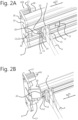
- Figures 2A-B give a perspective view on an end portion 8 of a possible guiding rail 6, further provided with a sliding element 5 and a blocking element 9; the guiding rail 6 itself has been omitted from Fig. 2B .
- the guiding rail 6 forms a longitudinal guiding channel 10 (not indicated), having a slit opening 11.
- the blocking element 9, coupled to the open end portion 8, further comprises a transverse cover 19. As such, it covers the guiding channel 10 at said end portion 8.
- the blocking element 9 further has two expansion anchors 17 (only one of which is visible in Fig. 2A ). These extend into two corresponding anchorage channels 18 (only one of which is visible in Fig. 2A ), formed by the guiding rail 6.
- the expansion anchors 17 have expandable sleeves. They are further adapted for receiving threaded fasteners 16, in which they expand outwardly and transversely. The expansion anchors 17 thus provide a coupling mechanism.
- a friction reducing insert 12 is further provided within said guiding channel 10.
- Latter insert 12 forms an insert channel 13, equally having a slit opening 11'.
- At least one sliding element 5 is slidably engaged within insert channel 13 (and thus also within the guiding channel 10 ) .
- the sliding element 5 is provided with an engagement portion 14.
- the sliding element 5 is thus able to move back and forth along the longitudinal direction 23, along the guiding channel 10.
- the sliding element 5 simultaneously provides a support 15 for the dunnage 4, through the aforementioned slit openings 11, 11'.
- the insert slit opening 11' is sufficiently narrow for retaining the sliding elements 5. As such, it does not allow for disengaging sliding elements 5 from the insert channel 13.
- the insert 12 does not extend over the entire length of the guiding rail 6. It has a cut-off 20. Additionally, in the embodiment shown, the slit opening 11 of the guiding channel 10 is wider than the slit opening 11' of the insert channel 13. By providing a wider opening, the slit opening 11 of the guiding channel 10 may allow for engaging and disengaging the sliding elements 5. See for instance Fig. 3D . As such, the guiding channel 10 slit opening 11 provides an engagement opening 21 at/beyond said cut-off 20. The cut-off 20 is more clearly visible in Fig. 2B , in which the guiding rail 6 has been omitted.
- the blocking element 9 has a blocking portion 22 that blocks a passage of the sliding element 5. More particularly, it prohibits the sliding element 5 to slide past the cut-off 20, where the engagement opening 21 is arranged. As such, the sliding element 5 cannot be disengaged, unless the blocking portion 22 is moved from its first position (shown in Fig. 2A-B ) into a second position, in which it allows said passage. See for instance the embodiment of Fig. 3A-B .
- the blocking element 9 preferably remains coupled to the guiding rail 6. At the same time, it is designed such that its blocking portion 22 can be moved into a second, non-blocking position.
- FIG. 3A-B A number of possible (and non-limiting) mechanisms is shown in Fig. 3A-B , Fig. 5 , and in Fig. 6 .
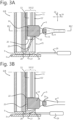
- Figures 3A-B each depict a horizontal cut of a guiding rail 6 end portion 8, accordingto a possible embodiment. The latter may correspond to the embodiment of Fig. 2A-B .
- the guiding rail 6 comprises a guiding channel 10 having a slit opening 11.
- An insert 12 is further provided within the guiding channel 10.
- Latter insert 12 comprises an insert channel 13, also having a slit opening 11'.
- a sliding element 5 is now slidably engaged within the insert channel 13, via its engagement portion 14. The sliding element 5 may simultaneously provide a support 15 for dunnage 4, through both slit openings 11, 11'.
- the insert 12 has a cut-off 20.
- the guiding rail 6 thereby provides an engagement opening 21.
- the latter is positioned at and beyond this cut-off 20.
- a blocking element 9 present on the guiding rail 6 sliding elements 5 cannot be disengaged from the insert channel 13 by coincidence.
- the blocking element 9 features a blocking portion 22.
- the blocking portion 22 is normally positioned in a first, blocking position (see Fig. 3A ). As such, it blocks the passage of the sliding element 5; it prevents the engagement portion 14 of the sliding element 5 from exiting the insert channel 13, in which they may subsequently pass through the engagement opening 21.
- the blocking element 9 is further adapted for its blocking portion 22 to be movable between a first position (see Fig. 3A ) and a second position (see Fig. 3B ).
- the blocking portion is formed by a lip 25.
- Said lip 25 may qualify as a resilient and/or pivotable member.
- the blocking element 5 of Fig. 3A-B is provided with a groove 26, near the base of the lip 25. This groove 26 provides a weakening.
- the lip 25 may therefore be pivoted, wherein the blocking portion 22 is moved from its first position into its second position.
- the lip 25 may be sufficiently thin, such that it is resiliently bendable.
- the blocking portion 22 is moved in a substantially transverse direction 24 w.r.t. the guiding rail, between its first and second positions.
- Fig. 3A shows the lip 25 and blocking portion 22 in their first, relaxed position.
- Fig. 3B shows the lip 25 and blocking portion 22 in their second, tensed position.
- the blocking element 5 In order to disengage the sliding element 5 from the guiding rail 6, the blocking portion 22 is moved into its second position.
- the blocking element 5 may comprise a lever 27.
- An outward edge 28 of said lever 27 is preferably chamfered.
- a fine tool e.g. a flat-blade screwdriver 29
- a fine tool may thus be forced in between the lever 27 and an adjacent structure - e.g. a container front side 3, referring back to Fig. 1A .
- This action causes the lever 27 and lip 25 to pivot within the guiding channel 10.
- the blocking portion 22 is thus moved away from the engagement opening 21, from its first position into its second position. Passage of the sliding element 5 is now allowed.
- the engagement portion 14 of the sliding element 5 may simply be removed from the guiding rail 6, through the engagement opening 21. This may or may not involve an unhooking movement, as shown in Fig. 3D .
- the blocking portion 22 is equally moved into its second position.
- the engagement portion 14 of the sliding element 5 may simply inserted into the guiding rail 6, through the engagement opening 21. This may or may not involve a hooking movement, as shown in Fig. 3D .
- the blocking portion 22 of the blocking element 9 is pushed away from the engagement opening 21; it is pushed into its second position. Only optionally the lever 27 is employed. It is now possible to slide the engagement portion 14 into the insert channel 13. The sliding element 5 is now engaged within the guiding channel 10 and insert channel 13.
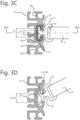
- Figures 3C-D show transverse cross-sections of the guiding rail 6 according to Fig.2A-B , and according to Fig. 3A-B .
- Fig. 3C the cross-section passes through an insert 12 that is provided within the guiding rail 6. Sliding elements 5 are engaged within the insert channel 13. One sliding element 5 is shown in particular. The cross-section plane of the figure thereby additionally passes through the sliding element (not indicated on the figure for reasons of clarity).
- the cross-section passes through the guiding rail 6 only (and not through the insert 12), at the level of a termination/interruption of the insert 12.
- the cross-section thus provides a view on the insert 12 cut-off 20.
- the engagement portion 14 of the sliding element 5 is slid past the blocking portion 22 (see Fig. 3B ), beyond the insert 12 cut-off 20.
- the sliding element 5 is positioned at cross-section level of the figure. Its engagement portion 14 is now hooking into / unhooking from the engagement opening 21.
- Transverse cross-section denotes that the cross-section is taken perpendicularly to the "longitudinal direction" of the guiding rail 6. All directions contained within such a transverse cross-section are referred to as "transverse directions”.
- Figures 4A-C give perspective views on a separate blocking element 9 according to a possible embodiment of the invention.
- the blocking element 9 may optionally correspond to any of Fig. 2A-B and 3A-D .
- the blocking element 9 can be coupled to an open end portion 8 of a guiding rail 6. To such end, it comprises two expansion anchors 17, each adapted for receiving a threaded fastener.
- the expansion anchors 17 are disposed on an inner side (visible in Fig. 4A and 4B ) of the transverse cover 19. They extend into a longitudinal direction w.r.t. the cover 19.
- the blocking element 9 provides a pivotable and/or bendable lip 25 that forms a blocking portion 22.
- the lip 25 extends inclined but substantially longitudinally, wherein the blocking portion 22 is positioned at an inner side w.r.t. the cover 19.
- a groove 26 is present near the base of the lip 25.
- the lip 25 is further provided with a lever 27 having a chamfered edge 28.
- the blocking element 9 is provided with further plugs 30, equally disposed on the inner side of the cover 19. Such plugs 30 may contribute to the blocking element's 9 coupling.
- Figure 5 illustrates an alternative embodiment of the guiding rail 6 and sliding elements 5.
- the sliding elements 5 have cuboid engagement portions 14. They may further provide a dunnage support 15 that passes from the guiding channel 10, through a slit opening 11 of the guiding rail 6.
- the guiding rail 6 does not have an insert 12, however.
- the sliding elements 5 are directly engaged with the guiding channel 10.
- the engagement opening 21 is currently arranged as a widening of the slit opening 11. In particular, the engagement opening 21 extends through a front and upper wall of the guiding channel 6.
- the engagement opening 21 is thus still arranged in a transverse direction (forward and upward) w.r.t the guiding rail 6.
- the blocking element 9 is further designed as a blocking pin 9. The latter passes through an aperture in the lower wall of the guiding channel 6.
- Figure 6 gives an exploded view on yet an alternative embodiment of the guiding rail 6.
- the guiding rail 6 does not have an insert 12.
- the engagement opening 21 is oriented longitudinally 23 instead of transversely 24.
- the blocking element 9 features a movable lip 25 that provides a blocking portion 22.
- a groove 26 is (optionally) provided at the base of the lip 25, such that the lip 25 can be pivoted resiliently. Additionally or alternatively, the lip 25 itself can be bended resiliently.
- the blocking portion 22 can be moved resiliently between a first relaxed position and a second tensed position, in a substantially transverse direction 24 w.r.t. the guiding rail 6.
- the blocking element 9 can further be coupled to the open end portion 8 of the guiding rail 6. To such end, a transverse threaded fastener 16 is provided. Even in the coupled configuration, sliding elements 5 can be slid over the blocking element 9, and past the blocking portion 22.
- the lip 25 and its blocking portion 22 are automatically brought into their second/non-blocking position. Once the blocking element 9 has passed the blocking portion 22, the latter will automatically return to its first/blocking position.
- the sliding element is now engaged within the guiding channel 10 (not shown). Its provides a support 15 through the slit opening 11 of the guiding rail 6.
Landscapes
- Engineering & Computer Science (AREA)
- Mechanical Engineering (AREA)
- Bag Frames (AREA)
- Packging For Living Organisms, Food Or Medicinal Products That Are Sensitive To Environmental Conditiond (AREA)
- Packaging Of Annular Or Rod-Shaped Articles, Wearing Apparel, Cassettes, Or The Like (AREA)
- Vehicle Step Arrangements And Article Storage (AREA)
Applications Claiming Priority (3)
| Application Number | Priority Date | Filing Date | Title |
|---|---|---|---|
| DE202019001052 | 2019-03-07 | ||
| DE202019104028.9U DE202019104028U1 (de) | 2019-03-07 | 2019-07-22 | Führungsschiene und Transportbehälter |
| PCT/EP2020/056154 WO2020178454A1 (en) | 2019-03-07 | 2020-03-09 | Guiding rail and transport container |
Publications (3)
| Publication Number | Publication Date |
|---|---|
| EP3934992A1 EP3934992A1 (en) | 2022-01-12 |
| EP3934992C0 EP3934992C0 (en) | 2024-06-12 |
| EP3934992B1 true EP3934992B1 (en) | 2024-06-12 |
Family
ID=68276681
Family Applications (1)
| Application Number | Title | Priority Date | Filing Date |
|---|---|---|---|
| EP20712867.9A Active EP3934992B1 (en) | 2019-03-07 | 2020-03-09 | Transport container, guiding rail and associated methods |
Country Status (8)
| Country | Link |
|---|---|
| US (1) | US12258174B2 (pl) |
| EP (1) | EP3934992B1 (pl) |
| BE (1) | BE1027072B1 (pl) |
| DE (1) | DE202019104028U1 (pl) |
| ES (1) | ES2986603T3 (pl) |
| HU (1) | HUE067802T2 (pl) |
| PL (1) | PL3934992T3 (pl) |
| WO (1) | WO2020178454A1 (pl) |
Families Citing this family (4)
| Publication number | Priority date | Publication date | Assignee | Title |
|---|---|---|---|---|
| US11376781B2 (en) * | 2018-07-18 | 2022-07-05 | Feurer Febra Gmbh | Transport device |
| DE202019104028U1 (de) | 2019-03-07 | 2019-09-26 | Conteyor International Nv | Führungsschiene und Transportbehälter |
| BE1028553B1 (nl) | 2020-08-20 | 2022-03-21 | Conteyor Int Nv | Opslaginrichting met verticaal beweegbaar gordijn en kit voor bevestiging van verticaal beweegbaar gordijn aan opslaginrichting |
| DE102020134735A1 (de) * | 2020-12-22 | 2022-06-23 | Carl-Peter Schoene | Baukastensystem zur Herstellung eines Lager- und Transportelementes, Verwendung eines Baukastensystems sowie Lager- und Transportelement |
Family Cites Families (11)
| Publication number | Priority date | Publication date | Assignee | Title |
|---|---|---|---|---|
| AT404313B (de) | 1994-10-05 | 1998-10-27 | Fulterer Gmbh | Schubkastenführung für ausziehbare möbelteile |
| DE202005005489U1 (de) * | 2005-04-07 | 2005-06-09 | Paul Hettich Gmbh & Co. Kg | Teleskopführung für ein in einem Möbelkorpus verschiebbar angeordnetes Möbelteil |
| US9016507B2 (en) * | 2011-09-06 | 2015-04-28 | Bradford Company | Container having sliding support assemblies for supporting dunnage |
| US9120597B2 (en) * | 2011-09-06 | 2015-09-01 | Bradford Company | Container having sliding support members for supporting dunnage |
| US9010563B2 (en) | 2012-09-14 | 2015-04-21 | Bradford Company | Container having metal outer frame for supporting L-shaped tracks |
| US9211999B2 (en) | 2013-11-15 | 2015-12-15 | Bradford Company | Container having non-linear tracks for supporting movable dunnage |
| US9731863B2 (en) * | 2013-11-21 | 2017-08-15 | Bradford Company | Container having multiple levels of slots to facilitate movement of dunnage |
| CZ31259U1 (cs) | 2015-11-06 | 2017-12-04 | Conteyor International Nv | Vodicí konzola vybavená vloženým materiálem a zařízení vybavené takovou vodicí konzolou |
| US11174071B2 (en) * | 2016-04-28 | 2021-11-16 | Bradford Company | Container having multiple layers of lockable crossbar assemblies for keeping products inside container |
| US11254483B2 (en) * | 2016-04-28 | 2022-02-22 | Bradford Company | Container having at least one lockable crossbar assembly movable along tracks |
| DE202019104028U1 (de) | 2019-03-07 | 2019-09-26 | Conteyor International Nv | Führungsschiene und Transportbehälter |
-
2019
- 2019-07-22 DE DE202019104028.9U patent/DE202019104028U1/de active Active
-
2020
- 2020-03-09 US US17/435,444 patent/US12258174B2/en active Active
- 2020-03-09 PL PL20712867.9T patent/PL3934992T3/pl unknown
- 2020-03-09 BE BE20205159A patent/BE1027072B1/nl active IP Right Grant
- 2020-03-09 EP EP20712867.9A patent/EP3934992B1/en active Active
- 2020-03-09 HU HUE20712867A patent/HUE067802T2/hu unknown
- 2020-03-09 WO PCT/EP2020/056154 patent/WO2020178454A1/en not_active Ceased
- 2020-03-09 ES ES20712867T patent/ES2986603T3/es active Active
Also Published As
| Publication number | Publication date |
|---|---|
| BE1027072A1 (nl) | 2020-09-14 |
| US12258174B2 (en) | 2025-03-25 |
| DE202019104028U1 (de) | 2019-09-26 |
| EP3934992C0 (en) | 2024-06-12 |
| WO2020178454A1 (en) | 2020-09-10 |
| HUE067802T2 (hu) | 2024-11-28 |
| US20220055796A1 (en) | 2022-02-24 |
| BE1027072B1 (nl) | 2021-04-02 |
| ES2986603T3 (es) | 2024-11-12 |
| PL3934992T3 (pl) | 2024-10-14 |
| EP3934992A1 (en) | 2022-01-12 |
Similar Documents
| Publication | Publication Date | Title |
|---|---|---|
| US12258174B2 (en) | Guiding rail and transport container | |
| US6321622B1 (en) | Structure for attaching a suspending device to an electric power tool | |
| US9428092B2 (en) | Sliding and removable cup holder assembly for vehicle | |
| US9364089B1 (en) | Self-closing slide rail assembly with deceleration mechanism | |
| EP3330475B2 (en) | Rail for an architectural opening covering | |
| US10323916B2 (en) | Mechanical Broadhead | |
| DE102006057582B4 (de) | Kühlschrankschienenanordnung und Kühlschranklagerbehälterauszugs-/-Einschubvorrichtung mit derselben | |
| PT2150151E (pt) | Dispositivo para assegurar um final suave do movimento de abertura de uma gaveta | |
| US20130152744A1 (en) | Automatic screw feeding device | |
| US20150353019A1 (en) | Sliding and removable cup holder assembly for vehicle | |
| US20040240933A1 (en) | Arrangement for receiving a lockable and releasable push-in element and method | |
| KR20170031218A (ko) | 레일 장착 클립을 가진 제품 관리 디스플레이 시스템 | |
| JP2017519924A (ja) | スライドドア用の嵌合具 | |
| RU2719061C1 (ru) | Держатель груза автомобиля и содержащая его система | |
| US10694732B2 (en) | Storage device | |
| JP2004256090A (ja) | 開放式屋根構造体において使用されるサンシェードおよびこのサンシェードを備えた開放式屋根構造体 | |
| EP4620733A1 (en) | System for adjusting the height of cargo boxes on trailers and the like | |
| US7066370B2 (en) | Cassette for stapler | |
| GB2333122A (en) | Window stay with latch for selective locking | |
| TWI526176B (zh) | Drawer cabinets and drawer sliders with sliding parts | |
| JP4474623B2 (ja) | シャッター装置のガイドレール構造 | |
| WO2022038569A1 (en) | Storage device with vertically movable curtain and kit for attaching vertically movable curtain to storage device | |
| US3421470A (en) | Jib hook magazine | |
| JP4936471B2 (ja) | 引込機構 | |
| CN108820030B (zh) | 一种手推车座架换向构造 |
Legal Events
| Date | Code | Title | Description |
|---|---|---|---|
| STAA | Information on the status of an ep patent application or granted ep patent |
Free format text: STATUS: UNKNOWN |
|
| STAA | Information on the status of an ep patent application or granted ep patent |
Free format text: STATUS: THE INTERNATIONAL PUBLICATION HAS BEEN MADE |
|
| PUAI | Public reference made under article 153(3) epc to a published international application that has entered the european phase |
Free format text: ORIGINAL CODE: 0009012 |
|
| STAA | Information on the status of an ep patent application or granted ep patent |
Free format text: STATUS: REQUEST FOR EXAMINATION WAS MADE |
|
| 17P | Request for examination filed |
Effective date: 20211006 |
|
| AK | Designated contracting states |
Kind code of ref document: A1 Designated state(s): AL AT BE BG CH CY CZ DE DK EE ES FI FR GB GR HR HU IE IS IT LI LT LU LV MC MK MT NL NO PL PT RO RS SE SI SK SM TR |
|
| DAV | Request for validation of the european patent (deleted) | ||
| DAX | Request for extension of the european patent (deleted) | ||
| REG | Reference to a national code |
Ref country code: DE Ref legal event code: R079 Free format text: PREVIOUS MAIN CLASS: B65D0019060000 Ipc: B65D0019440000 Ref document number: 602020032279 Country of ref document: DE |
|
| RIC1 | Information provided on ipc code assigned before grant |
Ipc: B65D 19/06 20060101ALI20231207BHEP Ipc: B65D 19/38 20060101ALI20231207BHEP Ipc: B65D 19/44 20060101AFI20231207BHEP |
|
| GRAP | Despatch of communication of intention to grant a patent |
Free format text: ORIGINAL CODE: EPIDOSNIGR1 |
|
| STAA | Information on the status of an ep patent application or granted ep patent |
Free format text: STATUS: GRANT OF PATENT IS INTENDED |
|
| INTG | Intention to grant announced |
Effective date: 20240119 |
|
| GRAS | Grant fee paid |
Free format text: ORIGINAL CODE: EPIDOSNIGR3 |
|
| GRAA | (expected) grant |
Free format text: ORIGINAL CODE: 0009210 |
|
| STAA | Information on the status of an ep patent application or granted ep patent |
Free format text: STATUS: THE PATENT HAS BEEN GRANTED |
|
| AK | Designated contracting states |
Kind code of ref document: B1 Designated state(s): AL AT BE BG CH CY CZ DE DK EE ES FI FR GB GR HR HU IE IS IT LI LT LU LV MC MK MT NL NO PL PT RO RS SE SI SK SM TR |
|
| REG | Reference to a national code |
Ref country code: GB Ref legal event code: FG4D |
|
| REG | Reference to a national code |
Ref country code: CH Ref legal event code: EP |
|
| REG | Reference to a national code |
Ref country code: IE Ref legal event code: FG4D |
|
| REG | Reference to a national code |
Ref country code: DE Ref legal event code: R096 Ref document number: 602020032279 Country of ref document: DE |
|
| U01 | Request for unitary effect filed |
Effective date: 20240712 |
|
| U07 | Unitary effect registered |
Designated state(s): AT BE BG DE DK EE FI FR IT LT LU LV MT NL PT SE SI Effective date: 20240722 |
|
| REG | Reference to a national code |
Ref country code: SK Ref legal event code: T3 Ref document number: E 44665 Country of ref document: SK |
|
| PG25 | Lapsed in a contracting state [announced via postgrant information from national office to epo] |
Ref country code: HR Free format text: LAPSE BECAUSE OF FAILURE TO SUBMIT A TRANSLATION OF THE DESCRIPTION OR TO PAY THE FEE WITHIN THE PRESCRIBED TIME-LIMIT Effective date: 20240612 |
|
| PG25 | Lapsed in a contracting state [announced via postgrant information from national office to epo] |
Ref country code: GR Free format text: LAPSE BECAUSE OF FAILURE TO SUBMIT A TRANSLATION OF THE DESCRIPTION OR TO PAY THE FEE WITHIN THE PRESCRIBED TIME-LIMIT Effective date: 20240913 |
|
| PG25 | Lapsed in a contracting state [announced via postgrant information from national office to epo] |
Ref country code: NO Free format text: LAPSE BECAUSE OF FAILURE TO SUBMIT A TRANSLATION OF THE DESCRIPTION OR TO PAY THE FEE WITHIN THE PRESCRIBED TIME-LIMIT Effective date: 20240912 Ref country code: HR Free format text: LAPSE BECAUSE OF FAILURE TO SUBMIT A TRANSLATION OF THE DESCRIPTION OR TO PAY THE FEE WITHIN THE PRESCRIBED TIME-LIMIT Effective date: 20240612 Ref country code: GR Free format text: LAPSE BECAUSE OF FAILURE TO SUBMIT A TRANSLATION OF THE DESCRIPTION OR TO PAY THE FEE WITHIN THE PRESCRIBED TIME-LIMIT Effective date: 20240913 Ref country code: RS Free format text: LAPSE BECAUSE OF FAILURE TO SUBMIT A TRANSLATION OF THE DESCRIPTION OR TO PAY THE FEE WITHIN THE PRESCRIBED TIME-LIMIT Effective date: 20240912 |
|
| REG | Reference to a national code |
Ref country code: ES Ref legal event code: FG2A Ref document number: 2986603 Country of ref document: ES Kind code of ref document: T3 Effective date: 20241112 |
|
| REG | Reference to a national code |
Ref country code: HU Ref legal event code: AG4A Ref document number: E067802 Country of ref document: HU |
|
| PG25 | Lapsed in a contracting state [announced via postgrant information from national office to epo] |
Ref country code: IS Free format text: LAPSE BECAUSE OF FAILURE TO SUBMIT A TRANSLATION OF THE DESCRIPTION OR TO PAY THE FEE WITHIN THE PRESCRIBED TIME-LIMIT Effective date: 20241012 |
|
| PG25 | Lapsed in a contracting state [announced via postgrant information from national office to epo] |
Ref country code: SM Free format text: LAPSE BECAUSE OF FAILURE TO SUBMIT A TRANSLATION OF THE DESCRIPTION OR TO PAY THE FEE WITHIN THE PRESCRIBED TIME-LIMIT Effective date: 20240612 |
|
| PG25 | Lapsed in a contracting state [announced via postgrant information from national office to epo] |
Ref country code: SM Free format text: LAPSE BECAUSE OF FAILURE TO SUBMIT A TRANSLATION OF THE DESCRIPTION OR TO PAY THE FEE WITHIN THE PRESCRIBED TIME-LIMIT Effective date: 20240612 Ref country code: IS Free format text: LAPSE BECAUSE OF FAILURE TO SUBMIT A TRANSLATION OF THE DESCRIPTION OR TO PAY THE FEE WITHIN THE PRESCRIBED TIME-LIMIT Effective date: 20241012 |
|
| PLBE | No opposition filed within time limit |
Free format text: ORIGINAL CODE: 0009261 |
|
| STAA | Information on the status of an ep patent application or granted ep patent |
Free format text: STATUS: NO OPPOSITION FILED WITHIN TIME LIMIT |
|
| U20 | Renewal fee for the european patent with unitary effect paid |
Year of fee payment: 6 Effective date: 20250325 |
|
| 26N | No opposition filed |
Effective date: 20250313 |
|
| PG25 | Lapsed in a contracting state [announced via postgrant information from national office to epo] |
Ref country code: MC Free format text: LAPSE BECAUSE OF FAILURE TO SUBMIT A TRANSLATION OF THE DESCRIPTION OR TO PAY THE FEE WITHIN THE PRESCRIBED TIME-LIMIT Effective date: 20240612 |
|
| REG | Reference to a national code |
Ref country code: CH Ref legal event code: H13 Free format text: ST27 STATUS EVENT CODE: U-0-0-H10-H13 (AS PROVIDED BY THE NATIONAL OFFICE) Effective date: 20251023 |
|
| PG25 | Lapsed in a contracting state [announced via postgrant information from national office to epo] |
Ref country code: CH Free format text: LAPSE BECAUSE OF NON-PAYMENT OF DUE FEES Effective date: 20250331 |
|
| PG25 | Lapsed in a contracting state [announced via postgrant information from national office to epo] |
Ref country code: IE Free format text: LAPSE BECAUSE OF NON-PAYMENT OF DUE FEES Effective date: 20250309 |
|
| PGFP | Annual fee paid to national office [announced via postgrant information from national office to epo] |
Ref country code: GB Payment date: 20260324 Year of fee payment: 7 |
|
| PGFP | Annual fee paid to national office [announced via postgrant information from national office to epo] |
Ref country code: RO Payment date: 20260303 Year of fee payment: 7 |
|
| PGFP | Annual fee paid to national office [announced via postgrant information from national office to epo] |
Ref country code: HU Payment date: 20260323 Year of fee payment: 7 |
|
| PGFP | Annual fee paid to national office [announced via postgrant information from national office to epo] |
Ref country code: TR Payment date: 20260303 Year of fee payment: 7 |
|
| PGFP | Annual fee paid to national office [announced via postgrant information from national office to epo] |
Ref country code: CZ Payment date: 20260304 Year of fee payment: 7 |
|
| PGFP | Annual fee paid to national office [announced via postgrant information from national office to epo] |
Ref country code: PL Payment date: 20260227 Year of fee payment: 7 |
|
| PGFP | Annual fee paid to national office [announced via postgrant information from national office to epo] |
Ref country code: SK Payment date: 20260306 Year of fee payment: 7 |
|
| U20 | Renewal fee for the european patent with unitary effect paid |
Year of fee payment: 7 Effective date: 20260326 |
|
| PG25 | Lapsed in a contracting state [announced via postgrant information from national office to epo] |
Ref country code: CY Free format text: LAPSE BECAUSE OF FAILURE TO SUBMIT A TRANSLATION OF THE DESCRIPTION OR TO PAY THE FEE WITHIN THE PRESCRIBED TIME-LIMIT Effective date: 20240612 |
|
| PGFP | Annual fee paid to national office [announced via postgrant information from national office to epo] |
Ref country code: ES Payment date: 20260430 Year of fee payment: 7 |