EP3934845B1 - Verfahren und vorrichtung zum ausrichten plattenförmiger werkstücke - Google Patents
Verfahren und vorrichtung zum ausrichten plattenförmiger werkstücke Download PDFInfo
- Publication number
- EP3934845B1 EP3934845B1 EP20719392.1A EP20719392A EP3934845B1 EP 3934845 B1 EP3934845 B1 EP 3934845B1 EP 20719392 A EP20719392 A EP 20719392A EP 3934845 B1 EP3934845 B1 EP 3934845B1
- Authority
- EP
- European Patent Office
- Prior art keywords
- plate
- workpiece
- stop
- type workpiece
- shelf
- Prior art date
- Legal status (The legal status is an assumption and is not a legal conclusion. Google has not performed a legal analysis and makes no representation as to the accuracy of the status listed.)
- Active
Links
Images


Classifications
-
- B—PERFORMING OPERATIONS; TRANSPORTING
- B23—MACHINE TOOLS; METAL-WORKING NOT OTHERWISE PROVIDED FOR
- B23Q—DETAILS, COMPONENTS, OR ACCESSORIES FOR MACHINE TOOLS, e.g. ARRANGEMENTS FOR COPYING OR CONTROLLING; MACHINE TOOLS IN GENERAL CHARACTERISED BY THE CONSTRUCTION OF PARTICULAR DETAILS OR COMPONENTS; COMBINATIONS OR ASSOCIATIONS OF METAL-WORKING MACHINES, NOT DIRECTED TO A PARTICULAR RESULT
- B23Q7/00—Arrangements for handling work specially combined with or arranged in, or specially adapted for use in connection with, machine tools, e.g. for conveying, loading, positioning, discharging, sorting
- B23Q7/04—Arrangements for handling work specially combined with or arranged in, or specially adapted for use in connection with, machine tools, e.g. for conveying, loading, positioning, discharging, sorting by means of grippers
-
- B—PERFORMING OPERATIONS; TRANSPORTING
- B23—MACHINE TOOLS; METAL-WORKING NOT OTHERWISE PROVIDED FOR
- B23Q—DETAILS, COMPONENTS, OR ACCESSORIES FOR MACHINE TOOLS, e.g. ARRANGEMENTS FOR COPYING OR CONTROLLING; MACHINE TOOLS IN GENERAL CHARACTERISED BY THE CONSTRUCTION OF PARTICULAR DETAILS OR COMPONENTS; COMBINATIONS OR ASSOCIATIONS OF METAL-WORKING MACHINES, NOT DIRECTED TO A PARTICULAR RESULT
- B23Q16/00—Equipment for precise positioning of tool or work into particular locations not otherwise provided for
- B23Q16/001—Stops, cams, or holders therefor
-
- B—PERFORMING OPERATIONS; TRANSPORTING
- B27—WORKING OR PRESERVING WOOD OR SIMILAR MATERIAL; NAILING OR STAPLING MACHINES IN GENERAL
- B27B—SAWS FOR WOOD OR SIMILAR MATERIAL; COMPONENTS OR ACCESSORIES THEREFOR
- B27B31/00—Arrangements for conveying, loading, turning, adjusting, or discharging the log or timber, specially designed for saw mills or sawing machines
-
- B—PERFORMING OPERATIONS; TRANSPORTING
- B27—WORKING OR PRESERVING WOOD OR SIMILAR MATERIAL; NAILING OR STAPLING MACHINES IN GENERAL
- B27M—WORKING OF WOOD NOT PROVIDED FOR IN SUBCLASSES B27B - B27L; MANUFACTURE OF SPECIFIC WOODEN ARTICLES
- B27M1/00—Working of wood not provided for in subclasses B27B - B27L, e.g. by stretching
- B27M1/08—Working of wood not provided for in subclasses B27B - B27L, e.g. by stretching by multi-step processes
Definitions
- the invention relates to a method for aligning plate-shaped workpieces according to the preamble of claim 1 and a device for aligning plate-shaped workpieces according to the preamble of claim 10 (see e.g. EP 3 241 788 A1 ).
- panel-shaped workpieces made of wood or wood substitutes must be aligned in a defined manner for further processing. This is usually done on a workpiece table, on which the workpieces are placed using a load-handling device and pushed against stops.
- load-handling devices e.g. suction clamps or the like
- the panels are usually picked up by the load-handling device in an undefined position or rotational orientation, this undefined position or rotational orientation is retained when the workpiece is placed on a shelf. In other words, the workpiece can be twisted relative to the stops. Since the load-handling devices can usually only be moved relatively roughly parallel to the shelf, there are no options for moving the workpieces cleanly against the stops.
- the invention is therefore based on the object of specifying a method and a device for aligning plate-shaped workpieces with which the described disadvantages do not occur and with which a proper movement of the plate-shaped workpiece on the support against stops is possible.
- a plate-shaped workpiece in particular made of wood or wood substitutes, is brought into engagement by a handling device with a load-bearing device designed in particular for lifting and placing the plate-shaped workpiece.
- a load-bearing device designed in particular for lifting and placing the plate-shaped workpiece.
- the method according to the invention now provides as an essential component that the handling device - in contrast to conventional devices - has a driver device.
- the driver device is designed according to the invention in such a way that when the plate-shaped workpiece is carried along, it enables it to rotate about an axis perpendicular to the plane described by the plate-shaped workpiece. In this way, when the handling device or the load-bearing device is moved, that a workpiece carried along by the carrier device can rotate against the stop when it is moved.
- the plate-shaped workpiece is only grasped by the carrier device after being placed on the shelf, without any further engagement with the load-bearing device, and is thus moved against the at least one stop by moving the carrier device relative to the shelf.
- the driver device is preferably part of the load-handling device and can be operated independently of the other load-handling device.
- an engagement position on the plate-shaped workpiece is determined by a machine control system.
- the driver device is then brought into engagement with the plate-shaped workpiece at the engagement position. Since the driver device defines the axis of rotation about which the plate-shaped workpiece rotates when traveling against the stop, the machine control system will determine, depending on the specific position of the deposited workpiece, where the optimal engagement point of the driver device is.
- the machine control system takes into account that the driver device is moved parallel to the workpiece plane in the direction of at least one stop and that the workpiece is rotated in the process.
- the at least one stop can comprise a detection device which detects the impact of a workpiece on the corresponding stop. Such detection serves primarily to to determine whether a workpiece with a given geometry is correctly positioned for further processing after striking.
- the impact is communicated to the machine control in the form of impact signals.
- the machine control evaluates the received impact signals in relation to the dimensions of the workpiece.
- the plate-shaped workpiece is first moved against a first stop and aligned therewith by moving the driver device in the engaged state with the plate-shaped workpiece and then moved against a second stop and aligned therewith.
- the workpiece is not only aligned in terms of direction, but it is also brought into a predetermined position.
- the plate-shaped workpiece is fixed against at least one stop on the support after travel. By fixing it after alignment, a control system can save the workpiece position data and use it for further movement of the workpiece.
- the load-bearing device and/or the driver device can be brought into engagement with the plate-shaped workpiece by suction.
- the engagement can also be quickly released again by suction.
- the workpiece is preferably aligned in a horizontal plane. In order to align the workpiece, especially when it is supported from below, is to be moved through the processing process, no large holding forces are required and the further transport can be carried out in a very energy-efficient manner.
- the load-bearing device and the driver device can be brought into engagement with the plate-shaped workpiece independently of one another, in particular by suction.
- the driver device is designed to be rotatable, in particular about an axis perpendicular to the plane of the plate-shaped workpiece. The workpiece can thus be rotated in the plane by the driver device engaged with the workpiece and moved parallel to the workpiece plane.
- the driver device is arranged on the load-carrying device.
- the driver device can be brought into engagement with the workpiece after the load-bearing device has placed the plate-shaped workpiece on the shelf. After the workpiece has been placed on the shelf, the load-bearing device releases the engagements so that the workpiece is only held by the driver device. If the driver device is provided on the load-bearing device, the driver device can use the translatory movement mimicry of the load-bearing device for alignment. If the driver device is therefore arranged on the load-bearing device, preferably it is then not displaceable relative to it parallel to the plane of the plate-shaped workpiece, the above-described movement of the driver device relative to the shelf for moving the workpiece against the at least one stop takes place by moving the load-bearing device.
- the alignment function of the driver device on the one or more stops can therefore be taken over to a large extent by the load-bearing device. This saves additional degrees of freedom of movement - which may be necessary for displacement parallel to the plane of the plate-shaped workpiece - which are already present in the load-bearing device.
- the driver device can be provided separately from the load-handling device and can be moved independently of it.
- the driver device can be designed to be movable perpendicular to the workpiece plane within the load-handling device.
- the load-bearing device and/or the driver device is movable in at least two different spatial directions (X, Y), in particular those perpendicular to one another and running parallel to the plane of the plate-shaped workpiece.
- the at least one stop is movable. This means that it can be easily adapted to the dimensions of the workpiece and the subsequent processing steps.
- the at least one stop comprises a detection device which is designed to detect when a workpiece is in contact with the stop.
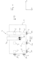
- Figure 1 shows a schematic plan view of a plate-shaped workpiece 1 that is arranged on a support 5, which is indicated here by dashed squares.
- the arrangement shown here is selected so that the plate-shaped workpiece 1 is aligned horizontally.
- stops 2, 3 are arranged on two adjacent sides of the workpiece 1 so that when the stops 2, 3, in particular all of them, are touched, the workpiece 1 is in the desired position.
- the stops 2, 3 are preferably individually adjustable so that they can be aligned according to the contour of the workpiece 1. This is particularly advantageous if the plate-shaped workpiece 1 is not a rectangular workpiece.
- Each of the stops 2, 3 can preferably be equipped with a detection device 2a, 3a, which detects the stop of the workpiece 1 and thus signals to the control that the target position of the workpiece 1 has been reached at the stop 2, 3 as long as the workpiece 1 touches the stop 2, 3.
- a handling device 4 is arranged above the plate-shaped workpiece 1, which has at least one, here for example two, load-bearing device(s) 41, 42 and a driver device 43.
- the driver device 43 is preferably arranged rotatably on a load-bearing device 41, 42, while the load-bearing device 41, 42 can be moved parallel to the spatial directions X and Y and the height Z.
- the load-bearing devices 41, 42 are engaged with the plate-shaped workpiece 1 and transport it to the support 5, on which they place it. Lying on the support 5, the workpiece 1 can be easily moved in the plane.
- the support 5 can be used for this purpose rollers, sliding elements, air cushions or other supporting elements.
- the load-bearing device 41, 42 releases the workpiece 1 when it comes to rest on the support 5.
- the arranged driver device 43 is brought into engagement with the workpiece. This is preferably done by means of suction.
- Figure 3 shows the orientation of the workpiece 1 on the first side, which faces the stops 2.
- the load-bearing device 41, 42 moves in the X direction, in particular the load-bearing device 42 on which it is arranged opposite the rotatable driver device 43, towards the stops 2.
- the original position of the workpiece 1 indicates that the right stop 2 is touched first by the workpiece 1 when the workpiece 1 is moved in the X direction by means of the driver device 43.
- the load-bearing devices 41, 42 are moved further in the X direction, the workpiece 1 rotates counterclockwise until it rests against all stops 2 and all three detection devices 2a of the side report an equal pressure P1 to the control system.
- Figure 4 shows the next step of alignment, in which the workpiece 1 is pressed against the stops 3 on the adjacent side.
- the load-bearing device 41, 42 moves with the driver device 43 in the Y direction until the workpiece 1 presses against the stops 3 in the direction P3.
- light pressure P2 is maintained against the first stops 2 so that the first alignment is not lost due to the movement.
Landscapes
- Engineering & Computer Science (AREA)
- Mechanical Engineering (AREA)
- Life Sciences & Earth Sciences (AREA)
- Wood Science & Technology (AREA)
- Forests & Forestry (AREA)
- Container, Conveyance, Adherence, Positioning, Of Wafer (AREA)
- Warehouses Or Storage Devices (AREA)
- Automatic Assembly (AREA)
Applications Claiming Priority (2)
| Application Number | Priority Date | Filing Date | Title |
|---|---|---|---|
| DE102019109864.5A DE102019109864A1 (de) | 2019-04-15 | 2019-04-15 | Verfahren und Vorrichtung zum Ausrichten plattenförmiger Werkstücke |
| PCT/EP2020/060389 WO2020212306A1 (de) | 2019-04-15 | 2020-04-14 | Verfahren und vorrichtung zum ausrichten plattenförmiger werkstücke |
Publications (2)
| Publication Number | Publication Date |
|---|---|
| EP3934845A1 EP3934845A1 (de) | 2022-01-12 |
| EP3934845B1 true EP3934845B1 (de) | 2025-01-08 |
Family
ID=70289779
Family Applications (1)
| Application Number | Title | Priority Date | Filing Date |
|---|---|---|---|
| EP20719392.1A Active EP3934845B1 (de) | 2019-04-15 | 2020-04-14 | Verfahren und vorrichtung zum ausrichten plattenförmiger werkstücke |
Country Status (4)
| Country | Link |
|---|---|
| EP (1) | EP3934845B1 (pl) |
| DE (1) | DE102019109864A1 (pl) |
| PL (1) | PL3934845T3 (pl) |
| WO (1) | WO2020212306A1 (pl) |
Family Cites Families (5)
| Publication number | Priority date | Publication date | Assignee | Title |
|---|---|---|---|---|
| US4790584A (en) * | 1986-06-09 | 1988-12-13 | Teradyne, Inc. | Compliant link |
| WO2003090969A1 (en) * | 2002-04-26 | 2003-11-06 | Strobbe Graphics N.V. | Positioning device, especially for offset plates |
| DE102014008016B4 (de) * | 2014-05-27 | 2024-10-10 | Ima Schelling Deutschland Gmbh | Verfahren zur Ausrichtung plattenförmiger Werkstücke auf einer Fördereinrichtung einer Bearbeitungsmaschine und Bearbeitungsmaschine |
| ITUA20163215A1 (it) * | 2016-05-06 | 2017-11-06 | Biesse Spa | Manipolatore per il trasferimento di pannelli di legno o simili |
| DE102018111810A1 (de) * | 2018-05-16 | 2019-11-21 | Homag Plattenaufteiltechnik Gmbh | Handhabungseinrichtung zum Handhaben eines plattenförmigen Werkstücks, Plattenbearbeitungsanlage, Verfahren zum Betreiben einer Handhabungseinrichtung, sowie Steuer- und/oder Regeleinrichtung |
-
2019
- 2019-04-15 DE DE102019109864.5A patent/DE102019109864A1/de active Pending
-
2020
- 2020-04-14 EP EP20719392.1A patent/EP3934845B1/de active Active
- 2020-04-14 PL PL20719392.1T patent/PL3934845T3/pl unknown
- 2020-04-14 WO PCT/EP2020/060389 patent/WO2020212306A1/de not_active Ceased
Also Published As
| Publication number | Publication date |
|---|---|
| EP3934845A1 (de) | 2022-01-12 |
| WO2020212306A1 (de) | 2020-10-22 |
| PL3934845T3 (pl) | 2025-04-28 |
| DE102019109864A1 (de) | 2020-10-15 |
Similar Documents
| Publication | Publication Date | Title |
|---|---|---|
| EP0494404A1 (de) | Platterzuführvorrichtung für Plattenaufteilsägen | |
| DE202008012632U1 (de) | Bearbeitungsmaschine für sechsseitige Bearbeitung | |
| DE3622922C2 (pl) | ||
| WO2019219755A1 (de) | Plattenbearbeitungsanlage, verfahren zum betreiben einer plattenbearbeitungsanlage, sowie steuer- und/oder regeleinrichtung | |
| AT501784B1 (de) | Plattenaufteilsäge | |
| DE4234536C2 (de) | Anlage zum Schneiden von Glasscheiben | |
| EP0304928A1 (de) | Einrichtsystem, insbesondere für eine Werkzeugmaschine | |
| EP2457675B1 (de) | Aufnahmeeinheit für Werkstücke | |
| DE19615251C2 (de) | Verfahren und Vorrichtung zum Bearbeiten von Werkstücken in einer Gesenkbiegepresse | |
| DE102010010746A1 (de) | Plattenbearbeitungsanlage | |
| DE3621640C1 (de) | Einrichtung zum Aufbringen von lokal einwirkenden Druckkraeften auf eine Glasscheibe innerhalb einer Fertigungslinie fuer Autoglasscheiben | |
| EP3093078A1 (de) | Verfahren und vorrichtung zum abführen eines werkstücks mit einem unebenen oder konturierten flächenabschnitt aus einer bearbeitungsmaschine | |
| EP2184116A1 (de) | Verfahren zum Ausschleusen von Blechteilen aus Stanzmaschinen | |
| EP3934845B1 (de) | Verfahren und vorrichtung zum ausrichten plattenförmiger werkstücke | |
| EP0566770A1 (de) | Verfahren und Vorrichtung zum Aufteilen von Platten und Bearbeiten der durch das Aufteilen erzeugten Werkstücke | |
| EP3362201B1 (de) | Verfahren zum betreiben einer biegepresse und solche biegepresse | |
| EP3461607B1 (de) | Werkstückbearbeitungsanlage, sowie verfahren zum betreiben einer werkstückbearbeitungsanlage | |
| EP2353813A1 (de) | Plattenbearbeitungsanlage | |
| WO2020120352A1 (de) | Verfahren zum verarbeiten plattenförmiger werkstücke | |
| EP3624989A1 (de) | Beschickungsvorrichtung und beschickungsverfahren | |
| DE102020115230B4 (de) | Verfahren zum Verarbeiten plattenförmiger Werkstücke | |
| DE4412392A1 (de) | Vorrichtung zum Bearbeiten von Holz- oder Kunststoffplatten | |
| DE10311693B3 (de) | Brechvorrichtung für das Vereinzelnen von Keramikleiterplatten | |
| DE102010060179B4 (de) | Metall-Fräsvorrichtung und Verfahren zum Bearbeiten von Längskanten eines Mehrkantprofils aus Metall | |
| DE4316338C2 (de) | Halte- und Transportvorrichtung für insbesondere flächige Werkstücke |
Legal Events
| Date | Code | Title | Description |
|---|---|---|---|
| STAA | Information on the status of an ep patent application or granted ep patent |
Free format text: STATUS: UNKNOWN |
|
| STAA | Information on the status of an ep patent application or granted ep patent |
Free format text: STATUS: THE INTERNATIONAL PUBLICATION HAS BEEN MADE |
|
| PUAI | Public reference made under article 153(3) epc to a published international application that has entered the european phase |
Free format text: ORIGINAL CODE: 0009012 |
|
| STAA | Information on the status of an ep patent application or granted ep patent |
Free format text: STATUS: REQUEST FOR EXAMINATION WAS MADE |
|
| 17P | Request for examination filed |
Effective date: 20201119 |
|
| AK | Designated contracting states |
Kind code of ref document: A1 Designated state(s): AL AT BE BG CH CY CZ DE DK EE ES FI FR GB GR HR HU IE IS IT LI LT LU LV MC MK MT NL NO PL PT RO RS SE SI SK SM TR |
|
| DAV | Request for validation of the european patent (deleted) | ||
| DAX | Request for extension of the european patent (deleted) | ||
| REG | Reference to a national code |
Ref country code: DE Ref legal event code: R079 Ref document number: 502020010154 Country of ref document: DE Free format text: PREVIOUS MAIN CLASS: B23Q0007040000 Ipc: B27B0031000000 |
|
| GRAP | Despatch of communication of intention to grant a patent |
Free format text: ORIGINAL CODE: EPIDOSNIGR1 |
|
| STAA | Information on the status of an ep patent application or granted ep patent |
Free format text: STATUS: GRANT OF PATENT IS INTENDED |
|
| RIC1 | Information provided on ipc code assigned before grant |
Ipc: B27M 1/08 20060101ALI20240701BHEP Ipc: B27B 31/00 20060101AFI20240701BHEP |
|
| INTG | Intention to grant announced |
Effective date: 20240805 |
|
| GRAS | Grant fee paid |
Free format text: ORIGINAL CODE: EPIDOSNIGR3 |
|
| GRAA | (expected) grant |
Free format text: ORIGINAL CODE: 0009210 |
|
| STAA | Information on the status of an ep patent application or granted ep patent |
Free format text: STATUS: THE PATENT HAS BEEN GRANTED |
|
| AK | Designated contracting states |
Kind code of ref document: B1 Designated state(s): AL AT BE BG CH CY CZ DE DK EE ES FI FR GB GR HR HU IE IS IT LI LT LU LV MC MK MT NL NO PL PT RO RS SE SI SK SM TR |
|
| REG | Reference to a national code |
Ref country code: GB Ref legal event code: FG4D Free format text: NOT ENGLISH |
|
| REG | Reference to a national code |
Ref country code: CH Ref legal event code: EP |
|
| REG | Reference to a national code |
Ref country code: DE Ref legal event code: R096 Ref document number: 502020010154 Country of ref document: DE |
|
| REG | Reference to a national code |
Ref country code: IE Ref legal event code: FG4D Free format text: LANGUAGE OF EP DOCUMENT: GERMAN |
|
| REG | Reference to a national code |
Ref country code: LT Ref legal event code: MG9D |
|
| REG | Reference to a national code |
Ref country code: NL Ref legal event code: MP Effective date: 20250108 |
|
| PG25 | Lapsed in a contracting state [announced via postgrant information from national office to epo] |
Ref country code: NL Free format text: LAPSE BECAUSE OF FAILURE TO SUBMIT A TRANSLATION OF THE DESCRIPTION OR TO PAY THE FEE WITHIN THE PRESCRIBED TIME-LIMIT Effective date: 20250108 |
|
| PG25 | Lapsed in a contracting state [announced via postgrant information from national office to epo] |
Ref country code: RS Free format text: LAPSE BECAUSE OF FAILURE TO SUBMIT A TRANSLATION OF THE DESCRIPTION OR TO PAY THE FEE WITHIN THE PRESCRIBED TIME-LIMIT Effective date: 20250408 |
|
| PG25 | Lapsed in a contracting state [announced via postgrant information from national office to epo] |
Ref country code: FI Free format text: LAPSE BECAUSE OF FAILURE TO SUBMIT A TRANSLATION OF THE DESCRIPTION OR TO PAY THE FEE WITHIN THE PRESCRIBED TIME-LIMIT Effective date: 20250108 |
|
| PGFP | Annual fee paid to national office [announced via postgrant information from national office to epo] |
Ref country code: PL Payment date: 20250326 Year of fee payment: 6 Ref country code: DE Payment date: 20250616 Year of fee payment: 6 |
|
| PG25 | Lapsed in a contracting state [announced via postgrant information from national office to epo] |
Ref country code: ES Free format text: LAPSE BECAUSE OF FAILURE TO SUBMIT A TRANSLATION OF THE DESCRIPTION OR TO PAY THE FEE WITHIN THE PRESCRIBED TIME-LIMIT Effective date: 20250108 |
|
| PG25 | Lapsed in a contracting state [announced via postgrant information from national office to epo] |
Ref country code: NO Free format text: LAPSE BECAUSE OF FAILURE TO SUBMIT A TRANSLATION OF THE DESCRIPTION OR TO PAY THE FEE WITHIN THE PRESCRIBED TIME-LIMIT Effective date: 20250408 Ref country code: IS Free format text: LAPSE BECAUSE OF FAILURE TO SUBMIT A TRANSLATION OF THE DESCRIPTION OR TO PAY THE FEE WITHIN THE PRESCRIBED TIME-LIMIT Effective date: 20250508 |
|
| PG25 | Lapsed in a contracting state [announced via postgrant information from national office to epo] |
Ref country code: HR Free format text: LAPSE BECAUSE OF FAILURE TO SUBMIT A TRANSLATION OF THE DESCRIPTION OR TO PAY THE FEE WITHIN THE PRESCRIBED TIME-LIMIT Effective date: 20250108 |
|
| PG25 | Lapsed in a contracting state [announced via postgrant information from national office to epo] |
Ref country code: PT Free format text: LAPSE BECAUSE OF FAILURE TO SUBMIT A TRANSLATION OF THE DESCRIPTION OR TO PAY THE FEE WITHIN THE PRESCRIBED TIME-LIMIT Effective date: 20250508 Ref country code: LV Free format text: LAPSE BECAUSE OF FAILURE TO SUBMIT A TRANSLATION OF THE DESCRIPTION OR TO PAY THE FEE WITHIN THE PRESCRIBED TIME-LIMIT Effective date: 20250108 |
|
| PG25 | Lapsed in a contracting state [announced via postgrant information from national office to epo] |
Ref country code: BG Free format text: LAPSE BECAUSE OF FAILURE TO SUBMIT A TRANSLATION OF THE DESCRIPTION OR TO PAY THE FEE WITHIN THE PRESCRIBED TIME-LIMIT Effective date: 20250108 Ref country code: GR Free format text: LAPSE BECAUSE OF FAILURE TO SUBMIT A TRANSLATION OF THE DESCRIPTION OR TO PAY THE FEE WITHIN THE PRESCRIBED TIME-LIMIT Effective date: 20250409 |
|
| PG25 | Lapsed in a contracting state [announced via postgrant information from national office to epo] |
Ref country code: SE Free format text: LAPSE BECAUSE OF FAILURE TO SUBMIT A TRANSLATION OF THE DESCRIPTION OR TO PAY THE FEE WITHIN THE PRESCRIBED TIME-LIMIT Effective date: 20250108 |
|
| PG25 | Lapsed in a contracting state [announced via postgrant information from national office to epo] |
Ref country code: SM Free format text: LAPSE BECAUSE OF FAILURE TO SUBMIT A TRANSLATION OF THE DESCRIPTION OR TO PAY THE FEE WITHIN THE PRESCRIBED TIME-LIMIT Effective date: 20250108 |
|
| REG | Reference to a national code |
Ref country code: DE Ref legal event code: R097 Ref document number: 502020010154 Country of ref document: DE |
|
| PG25 | Lapsed in a contracting state [announced via postgrant information from national office to epo] |
Ref country code: DK Free format text: LAPSE BECAUSE OF FAILURE TO SUBMIT A TRANSLATION OF THE DESCRIPTION OR TO PAY THE FEE WITHIN THE PRESCRIBED TIME-LIMIT Effective date: 20250108 |
|
| PG25 | Lapsed in a contracting state [announced via postgrant information from national office to epo] |
Ref country code: EE Free format text: LAPSE BECAUSE OF FAILURE TO SUBMIT A TRANSLATION OF THE DESCRIPTION OR TO PAY THE FEE WITHIN THE PRESCRIBED TIME-LIMIT Effective date: 20250108 Ref country code: CZ Free format text: LAPSE BECAUSE OF FAILURE TO SUBMIT A TRANSLATION OF THE DESCRIPTION OR TO PAY THE FEE WITHIN THE PRESCRIBED TIME-LIMIT Effective date: 20250108 |
|
| PG25 | Lapsed in a contracting state [announced via postgrant information from national office to epo] |
Ref country code: RO Free format text: LAPSE BECAUSE OF FAILURE TO SUBMIT A TRANSLATION OF THE DESCRIPTION OR TO PAY THE FEE WITHIN THE PRESCRIBED TIME-LIMIT Effective date: 20250108 |
|
| PG25 | Lapsed in a contracting state [announced via postgrant information from national office to epo] |
Ref country code: SK Free format text: LAPSE BECAUSE OF FAILURE TO SUBMIT A TRANSLATION OF THE DESCRIPTION OR TO PAY THE FEE WITHIN THE PRESCRIBED TIME-LIMIT Effective date: 20250108 |
|
| PLBE | No opposition filed within time limit |
Free format text: ORIGINAL CODE: 0009261 |
|
| STAA | Information on the status of an ep patent application or granted ep patent |
Free format text: STATUS: NO OPPOSITION FILED WITHIN TIME LIMIT |
|
| REG | Reference to a national code |
Ref country code: CH Ref legal event code: L10 Free format text: ST27 STATUS EVENT CODE: U-0-0-L10-L00 (AS PROVIDED BY THE NATIONAL OFFICE) Effective date: 20251119 |
|
| REG | Reference to a national code |
Ref country code: CH Ref legal event code: H13 Free format text: ST27 STATUS EVENT CODE: U-0-0-H10-H13 (AS PROVIDED BY THE NATIONAL OFFICE) Effective date: 20251125 |