EP3934226B1 - A camera and a method - Google Patents
A camera and a method Download PDFInfo
- Publication number
- EP3934226B1 EP3934226B1 EP20183955.2A EP20183955A EP3934226B1 EP 3934226 B1 EP3934226 B1 EP 3934226B1 EP 20183955 A EP20183955 A EP 20183955A EP 3934226 B1 EP3934226 B1 EP 3934226B1
- Authority
- EP
- European Patent Office
- Prior art keywords
- electrical component
- electrical
- enclosure
- state
- air volume
- Prior art date
- Legal status (The legal status is an assumption and is not a legal conclusion. Google has not performed a legal analysis and makes no representation as to the accuracy of the status listed.)
- Active
Links
Images

Classifications
-
- G—PHYSICS
- G03—PHOTOGRAPHY; CINEMATOGRAPHY; ANALOGOUS TECHNIQUES USING WAVES OTHER THAN OPTICAL WAVES; ELECTROGRAPHY; HOLOGRAPHY
- G03B—APPARATUS OR ARRANGEMENTS FOR TAKING PHOTOGRAPHS OR FOR PROJECTING OR VIEWING THEM; APPARATUS OR ARRANGEMENTS EMPLOYING ANALOGOUS TECHNIQUES USING WAVES OTHER THAN OPTICAL WAVES; ACCESSORIES THEREFOR
- G03B17/00—Details of cameras or camera bodies; Accessories therefor
- G03B17/55—Details of cameras or camera bodies; Accessories therefor with provision for heating or cooling, e.g. in aircraft
-
- G—PHYSICS
- G02—OPTICS
- G02B—OPTICAL ELEMENTS, SYSTEMS OR APPARATUS
- G02B27/00—Optical systems or apparatus not provided for by any of the groups G02B1/00 - G02B26/00, G02B30/00
- G02B27/0006—Optical systems or apparatus not provided for by any of the groups G02B1/00 - G02B26/00, G02B30/00 with means to keep optical surfaces clean, e.g. by preventing or removing dirt, stains, contamination, condensation
-
- G—PHYSICS
- G03—PHOTOGRAPHY; CINEMATOGRAPHY; ANALOGOUS TECHNIQUES USING WAVES OTHER THAN OPTICAL WAVES; ELECTROGRAPHY; HOLOGRAPHY
- G03B—APPARATUS OR ARRANGEMENTS FOR TAKING PHOTOGRAPHS OR FOR PROJECTING OR VIEWING THEM; APPARATUS OR ARRANGEMENTS EMPLOYING ANALOGOUS TECHNIQUES USING WAVES OTHER THAN OPTICAL WAVES; ACCESSORIES THEREFOR
- G03B17/00—Details of cameras or camera bodies; Accessories therefor
- G03B17/02—Bodies
-
- G—PHYSICS
- G03—PHOTOGRAPHY; CINEMATOGRAPHY; ANALOGOUS TECHNIQUES USING WAVES OTHER THAN OPTICAL WAVES; ELECTROGRAPHY; HOLOGRAPHY
- G03B—APPARATUS OR ARRANGEMENTS FOR TAKING PHOTOGRAPHS OR FOR PROJECTING OR VIEWING THEM; APPARATUS OR ARRANGEMENTS EMPLOYING ANALOGOUS TECHNIQUES USING WAVES OTHER THAN OPTICAL WAVES; ACCESSORIES THEREFOR
- G03B37/00—Panoramic or wide-screen photography; Photographing extended surfaces, e.g. for surveying; Photographing internal surfaces, e.g. of pipe
- G03B37/04—Panoramic or wide-screen photography; Photographing extended surfaces, e.g. for surveying; Photographing internal surfaces, e.g. of pipe with cameras or projectors providing touching or overlapping fields of view
-
- H—ELECTRICITY
- H04—ELECTRIC COMMUNICATION TECHNIQUE
- H04N—PICTORIAL COMMUNICATION, e.g. TELEVISION
- H04N23/00—Cameras or camera modules comprising electronic image sensors; Control thereof
- H04N23/50—Constructional details
- H04N23/51—Housings
-
- H—ELECTRICITY
- H04—ELECTRIC COMMUNICATION TECHNIQUE
- H04N—PICTORIAL COMMUNICATION, e.g. TELEVISION
- H04N23/00—Cameras or camera modules comprising electronic image sensors; Control thereof
- H04N23/50—Constructional details
- H04N23/52—Elements optimising image sensor operation, e.g. for electromagnetic interference [EMI] protection or temperature control by heat transfer or cooling elements
-
- H—ELECTRICITY
- H04—ELECTRIC COMMUNICATION TECHNIQUE
- H04N—PICTORIAL COMMUNICATION, e.g. TELEVISION
- H04N23/00—Cameras or camera modules comprising electronic image sensors; Control thereof
- H04N23/60—Control of cameras or camera modules
- H04N23/62—Control of parameters via user interfaces
-
- H—ELECTRICITY
- H04—ELECTRIC COMMUNICATION TECHNIQUE
- H04N—PICTORIAL COMMUNICATION, e.g. TELEVISION
- H04N23/00—Cameras or camera modules comprising electronic image sensors; Control thereof
- H04N23/60—Control of cameras or camera modules
- H04N23/65—Control of camera operation in relation to power supply
- H04N23/651—Control of camera operation in relation to power supply for reducing power consumption by affecting camera operations, e.g. sleep mode, hibernation mode or power off of selective parts of the camera
Definitions
- the invention relates to a camera and to a method of counteracting an increase in humidity of an air volume inside a camera enclosure caused by a first electrical component being configured to be shifted from a first state to a second state, the second state being associated with an increase in heat dissipation from the first electrical component compared to the first state.
- EP 3 085 071 A1 discloses a thermal and power management system for use in a camera.
- the thermal and power management system is configured to control the operational parameters of various components inside the camera in order to keep the camera within a thermal budget and/or within a power budget.
- the system is also configured to control the operational parameters in such a manner that any adverse impact on the user experience is minimized.
- this document relates to controlling temperature and power consumption, but it does not mention any problems or any suggestions concerning how to address issues related to humidity inside the camera.
- heaters capable of heating the window and thereby reduce the tendency of condensation of water on the window of the enclosure.
- this increases the overall power consumption.
- Camera devices of today typically include polymer-based materials.
- at least parts of the enclosure, at least parts of a camera chassis, and at least parts of covers of electrical components include polymer-based materials.
- Polymers belong to a group of materials which typically entraps water molecules.
- the absolute humidity of air volumes inside the enclosure will typically increase when the power consumption of the electrical components increases.
- Another part of the inventive concept resides in a realization that it is possible to make active use of the fact that some materials, such as many polymers, has the property of being capable of absorbing or desorbing water molecules when surrounding temperature or humidity level changes.
- some materials, such as many polymers has the property of being capable of absorbing water molecules when being cooled and desorbing water when being heated.
- the shift of the first electrical component from a first state to a second state, the second state being associated with an increase in heat dissipation from the first electrical component compared to heat dissipation from the first electrical component in the first state may refer to a situation where the first state is an off-state and the second state is an on-state or to a situation where the both the first and the second states are on-states; e.g. with the first state being a low power state and the second state being a high power state.
- the first electrical component may, e.g., be an IR LED element, where the first state is an off-state and the second state is an on-state.
- the first electrical component may be a heater.
- a heater is typically designed to be capable of being set at a plurality of different power levels.
- the first state is an off-state and the second state is an on-state.
- the first state is a low power on-state and the second state is a high power on-state.
- the second electrical component having a variable electrical power consumption may refer both to a second electrical component where the power consumption may be varied in a number of different levels, continuously or step-wise, but may also refer to a situation where the power consumption is varied only by being changed between an on-state and an off-state.
- the second electrical component may, e.g., be a step motor used to control focus and/or zoom of the camera and the electrical power consumption may be varied continuously, or in a plurality of different discrete values, e.g., by varying the hold current of the step motor.
- the step motor may also be referred to as a stepper motor or a stepping motor.
- decreasing the consumption of the second electrical component as the first electrical component is shifted to the second state is intended to refer to a simultaneity in practical terms.
- One way of controlling the camera is to provide the decrease in power consumption of the second electrical component in response to the shift in state of the first electrical component.
- the electronic circuitry of the camera may form a decision of a forthcoming shift in state of the first electrical component and that the power consumption of the second electrical component is decreased in response to this decision such that the temperature of the second electrical component has begun to slightly decrease at the point in time when the shift in state of the first electrical component is actually performed.
- the timing does not need to be exactly the same, there should be a simultaneity such that the decrease in temperature of the second electrical component counteracts the increase in humidity induced by the first electrical component.
- Reducing the electrical power consumption of the second electrical component and thereby reducing the temperature of the electrical component will also cause a reduction of a temperature of a material being positioned around, in contact with or at least nearby the second electrical component and being directly or indirectly in contact with an air volume such that the material, as the temperature reduces, absorbs moisture from the air volume.
- Nearby may be said to refer to material being so close or near the electrical component that activation of the electrical component causes the nearby material to be heated, such as by contact heating and radiation heating, by the electrical component such that the material dissipates heat to the first air volume.
- Being remote from the electrical component may be said to refer to materials being so far from the electrical component that the temperature of the material is to a greater extent controlled by another electrical component.
- the second portion of said material being cooled and thereby absorbing water molecules from the first air volume may be referred to as a moisture trap.
- the first portion of a material having the property of being capable of absorbing water molecules when being cooled and desorbing water when being heated may be of the same kind of material or may be different materials as long as it has or they have the property of being capable of absorbing water molecules when being cooled and desorbing water when being heated.
- Other design parameters such as electrical insulation, load bearing capacity, transparency, etc, may be set in respect of the different portions based on their respective position in the camera. Thereby, there might be a need to provide different kinds of materials having different properties.
- first and the second portion of a material having the property of being capable of absorbing water molecules when being cooled and desorbing water when being heated need not have the same rate of absorption and/or desorption at the same temperatures. It may even be suitable to have a first and a second portion having different temperature dependencies of the rates of absorption and/or desorption. With such a configuration it is possible to take into account situations where the first and second electrical components have different running temperatures, and/or where the first and second portions are influenced differently by the heat dissipation from the first, respectively, the second electrical component.
- the first and second portions are provided as a part of the enclosure and/or inside the enclosure.
- the first and the second electrical component are both in direct contact with the first air volume in the sense that the respective electrical component as such or a part of a cover or shell of the respective electrical component is in direct contact and in fluid communication with air in the first air volume.
- the first air volume may also be referred to as a common air volume.
- the first and the second electrical components are arranged at a distance from each other such that material of the enclosure, and/or material being positioned inside the enclosure, having the property of being capable of absorbing water molecules when being cooled and desorbing water when being heated and which is positioned nearby the first electrical component is considered to be positioned remote to the second electrical component, and vice versa.
- the first electrical component is in direct contact with the first air volume in the sense that the first electrical component as such or a part of a cover or shell of the electrical component is in direct contact and in fluid communication with air in the first air volume
- the second electrical component is in indirect contact with the first air volume in the sense that the second electrical component is in direct contact with a second air volume
- the first air volume and the second air volume being separated from each other by a separation wall capable of transfer heat from the first air volume to the second air volume, or vice versa, and at least part of the separation wall being formed of a material having the property of being capable of absorbing water molecules when being cooled and desorbing water when being heated.
- the first electrical component is arranged at a distance from the separation wall such that material of the enclosure or inside the enclosure which has the property of being capable of absorbing water molecules when being cooled and desorbing water when being heated and which is considered positioned nearby the first electrical component is considered to be positioned remote from the separation wall, and vice versa.
- the configuration is the reversed with the second electrical component being in direct contact with the first air volume and the first electrical component being in indirect contact with the first air volume.
- the first and the second electrical component are both in indirect contact with the first air volume in the sense that none of the respective electrical component as such nor any part of a cover or shell of the respective electrical component is in direct contact and in fluid communication with air in the first air volume, whereas both electrical components are in indirect contact with the first air volume in the sense that the respective electrical component is in direct contact with a respective air volume, the respective air volumes being separated from each other and from the first air volume by a respective separation wall capable of transfer heat from the respective air volume to the first air volume, or vice versa, the respective separation wall being formed of a material having the property of being capable of absorbing water molecules when being cooled and desorbing water when being heated.
- the first separation wall between the first air volume and the air volume associated with the first electrical component is arranged at a distance from the second separation wall between the first air volume and the air volume associated with the second electrical component such that the first separation wall is considered to be positioned remote from the second separation wall.
- the respective air volumes being separated from each other does not necessarily mean that there is no fluid connection at all. It is sufficient that the respective air volumes are separated from each other to such an extent that the first air volume will be experiencing different portions where one piece of material, such as the first separation wall, increases in temperature and one piece of material, such as the second separation wall, decreases in temperature. However, when both electrical components are in only indirect contact with the first air volume it is preferred that there is no fluid connection between the respective air volumes associated with the first and the second electrical components, respectively.
- the controller may be further arranged to restore electrical power consumption of the second electrical component after a predetermined time period or in response to a predetermined humidity condition related to the humidity of the first air volume inside the enclosure being fulfilled.
- the enclosure may comprise a window .
- One side of the window may face the first air volume inside the enclosure.
- the window may be in fluid communication with the first air volume inside the enclosure.
- In fluid communication with the first air volume is intended to refer to situations where the air of the first air volume inside the enclosure may flow through the camera such that there is formed a direct contact of the air with the window.
- This may be in the form of the window forming part of a main vessel enclosing the first air volume or the window forming part of a secondary vessel forming a communicating vessel with the main vessel.
- the concept disclosed is useful to reduce condensation of moisture on a window of an enclosure. It is not only suitable for cases where the window faces the first air volume, but the concept is considered especially useful for designs where the window faces the first air volume. Similarly, it is not only suitable for cases where the window is in fluid communication with the first air volume, but the concept is considered especially useful for designs where the window is in fluid communication with the first air volume inside the enclosure. The concept is considered especially useful for designs where the window is a window through which the camera is designed to view a scene.
- the first electrical component may be selected from a group consisting of: an electrical motor, such as an electrical step motor, a heater, a lighting element, such as an IR LED element, and a resistor.
- These electrical components are electrical components that often requires relatively rapid increase in electrical power consumption and which thereby may induce an increase in humidity of the first air volume inside the enclosure.
- the second electrical component may be selected from a group consisting of: an electrical motor, such as an electrical step motor, a heater, and a resistor.
- These electrical components are typically capable of providing heat and are thereby capable of drying the second portion of the material having the property of being capable of absorbing water molecules when being cooled and desorbing water when being heated. Alternatively expressed, these electrical components are typically capable of reducing their temperature when their power consumption is decreased, whereby the second portion of the material, having the property of being capable of absorbing water molecules when being cooled and desorbing water when being heated, may be cooled such that it absorbs water molecules.
- the electrical power consumption may be decreased by decreasing a hold current of the motor.
- the electrical power consumption may be decreased by decreasing the voltage and/or the current across the heater or resistor.
- At least the second portion may be formed of a polymer-based material.
- the polymer-based material of the second portion may form part of a cover of the electrical component.
- the polymer-based material of the second portion may form part of an attachment by which the electrical component is attached to the enclosure or to a camera chassis inside the enclosure.
- the polymer-based material of the second portion may form part of the enclosure.
- the first portion of said material is formed of a polymer-based material since it is as such useful as a cover or as part of an attachment of the first electrical component.
- Suitable materials to use are, e.g., polycarbonate; PC, as such or in combination with other polymers, such as polycarbonate and acrylonitrile butadiene styrene; PC+ABS, polycarbonate and polybutylene terephthalate; PC+PBT, polyamide; PA, acrylonitrile styrene acrylate; ASA.
- the controller may be configured to activate the second electrical element for a predetermined time period before it is contemplated to shift the first electrical component from the first state to the second state.
- the pre-heating may be performed smoothly such that any ordinary drying capacity of the camera is capable of taking care of the moisture induced by this pre-heating.
- the pre-heating may be an additional pre-heating not explicitly warranted by the ordinary function of the camera.
- the ordinary function of some of the electrical components of the camera may be regarded as a pre-heating. It is e.g. typical to provide a hold current to a step motor controlling e.g. the focus and/or zoom of the camera. This hold current provides in a sense a pre-heating which is also part of the ordinary function of the camera. It may be noted that it is also contemplated to increase the power consumption of the second electrical element for a pre-determined time period before it is contemplated to shift the first electrical component from the first state to the second state.
- the controller may be configured to keeping track off electrical power consumption of different electrical components of the camera and decreasing electrical power consumption of an electrical component which recently has had an electrical power consumption above a predetermined threshold value at which the electrical component has dissipated heat and dried and heated a piece of material having the property of being capable of absorbing water molecules when being cooled and desorbing water when being heated.
- the second electrical component will be determined dynamically based on the recent usage of the different electrical components of the camera.
- the second portion may be provided in the form of a moisture absorption element or the camera may further comprise a moisture absorption element, the moisture absorption element being arranged to absorb moisture from the first air volume when decreasing in temperature, the moisture absorption element being located nearby the second electrical component such that the temperature of the moisture absorption element decreases in response to a decrease in power consumption of the second electrical element.
- Suitable materials to use in such an absorption element is e.g. molecular sieve, silica gel, montmorillonite clay, calcium oxide; CaO, and calcium sulphate; CaSO 4
- the above mentioned object of the invention has also been achieved by a method of counteracting an increase in humidity of a first air volume inside an enclosure of a camera, the increase in humidity being induced by a first electrical component being shifted from a first state to a second state, the second state being associated with an increase in heat dissipation from the first electrical component compared to heat dissipation from the first electrical component in the first state, the first electrical component being at least partly positioned in the enclosure and being configured to directly or indirectly dissipate heat to the first air volume inside the enclosure, the method comprising: temporarily decreasing, as the first electrical component is shifted the second state, electrical power consumption of a second electrical component having a variable electrical power consumption, the second electrical component being at least partly arranged in the enclosure and being configured to directly or indirectly dissipate heat to the first air volume inside the enclosure.
- the method is characterised in that the controller temporarily decreasing electrical power consumption of the second electrical component counteracts an increase in humidity of the first air volume inside the enclosure, the increase in humidity being induced by the first electrical component being shifted to said second state and thereby heating a first portion of a material, the first portion having the property of being capable of absorbing water molecules when being cooled and desorbing water when being heated, and the increase in humidity being counteracted by a second portion of a material having the property of being capable of absorbing water molecules when being cooled and desorbing water when being heated being cooled and thereby absorbing water molecules from the first air volume, wherein the first portion is positioned nearby the first electrical component and remote from the second electrical component, and the second portion is positioned nearby the second electrical component and remote from the first electrical component.
- the method may further comprise: restoring electrical power consumption of the second electrical component after a predetermined time period and/or in response to a predetermined humidity condition related to the humidity of the first air volume inside the enclosure being fulfilled.
- the method may be used to counteract condensation of moisture on a window forming part of the enclosure.
- the window may have one side facing the first air volume inside the enclosure.
- the window may be in fluid communication with the first air volume inside the enclosure.
- the method may further comprise selecting the first electrical component from a group consisting of: an electrical motor, such as an electrical step motor, a heater, a lighting element, such as an IR LED element, and a resistor.
- an electrical motor such as an electrical step motor
- a heater such as an IR LED element
- a resistor such as an IR LED element
- the method may further comprise selecting the second electrical component from a group consisting of: an electrical motor, such as an electrical step motor, a heater, and a resistor.
- an electrical motor such as an electrical step motor, a heater, and a resistor.
- the method may further comprise: activating the second electrical component for a predetermined time period before it is contemplated to shift the first electrical component from the first state to the second state.
- the method may further comprise: providing a moisture absorption element, being arranged to absorb moisture from the first air volume when decreasing in temperature, nearby the second electrical component such that the temperature of the moisture absorption element decreases in response to a decrease in power consumption of the second electrical element.
- a moisture absorption element being arranged to absorb moisture from the first air volume when decreasing in temperature, nearby the second electrical component such that the temperature of the moisture absorption element decreases in response to a decrease in power consumption of the second electrical element.
- the invention may also in short be said to relate to a camera and a method of counteracting an increase in humidity of a first air volume inside an enclosure of a camera, the increase in humidity being induced by a first electrical component being shifted from a first state to a second state being associated with an increase in heat dissipation from the first electrical component, the first electrical component directly or indirectly dissipating heat to the first air volume, the method comprising: temporarily decreasing, as the first electrical component is shifted the second state, electrical power consumption of a second electrical component having a variable electrical power consumption, the second electrical component directly or indirectly dissipating heat to the first air volume.
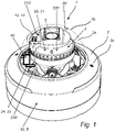
- FIG 1 there is disclosed a camera 1 in which the electronic circuitry and optics 3 of the camera 1 is enclosed in an enclosure 2.
- the enclosure 2 comprises a base part 2c and a window 2b.
- the window 2b is transparent such that light from the scene may enter through the window 2b, through the optics 3 to an image sensor (not shown).
- the imaging function of the optics 3, the image sensor, the electronic circuitry, etc. of the camera 1 is well-known to a person skilled in the art. Moreover, the specific choice of design of the imaging function of the camera 1 is not a crucial part of the inventive concept.
- the optics 3 and the image sensor is provided in an inner housing 4 positioned inside the enclosure 2.
- the inner housing 4 is supported by a chassis 5 inside the enclosure 2.
- the inner housing 4 is typically movable relative to the chassis 5 and the enclosure 2, such that the optics 3 and the image sensor may be oriented in different directions.
- the inventive concept is equally applicable for designs where the optics 3 is fixed relative to the chassis 5 and enclosure 2.
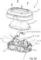
- FIGS 2a and 2b there is disclosed a variant of the camera 1 where there are two inner housings 4 provided inside a single enclosure 2 having a base part 2c and a window 2b. Each inner housing 4 is provided with its own optics 3 and its own image sensor.
- Both cameras 1 of figure 1 and of figures 2a-2b are provided with a lighting element in the form of IR LED elements 13.
- the IR LED elements 13 are arranged inside the enclosure 2.
- the IR LED elements 13 are provided on the inner housing 4.
- the IR LED elements 13 will be given different orientations relative to the enclosure 2.
- the IR LED elements 13 are provided on the chassis 5 of the camera 1.
- the IR LED elements 13 are examples of a first electrical component 10, as referred to in a general description of the inventive concept.
- the IR LED elements 13 are typically in an off-state, also referred to as a first state 10S1, during daytime and set in an on-state, also referred to as a second state 10S2, during night-time to illuminate the scene such that an IR sensitive image sensor may depict the scene.
- a first state 10S1 during daytime
- an on-state also referred to as a second state 10S2
- the IR LED elements 13 When the IR LED elements 13 are set in an on-state, they will become warm and heat will be dissipated from the IR LED elements 13.
- the heat will be dissipated to the air 2a inside the enclosure 2 and also to the portion 210 of the inner housing 4 nearby the LED elements 13.
- the heat will be dissipated to the air 2a inside the enclosure 2 and also to the portions 210 of the chassis 5 nearby the IR LED elements 13.
- the inner housing 4 and the chassis 5 typically comprise materials having the property of being capable of absorbing water molecules when being cooled and desorbing water when being heated.
- the materials typically include polymer-based materials.
- the activation of the IR LED elements 13 have, as such, a tendency to induce an increase in absolute humidity of the air 2a inside the enclosure since the activation of the IR LED elements 13 causes heating of the first portion 210 nearby the respective IR LED element 13, such that the material at the first portion 210 desorbs water into the air 2a.
- the camera 1 typically also comprises one or more electrical motors 21 positioned inside the inner housing 4, and thus also inside the enclosure 2.
- the electrical motors 21 are provided to move different parts of the optics 3 relative to each other and/or relative to the image sensor to thereby control zoom and/or focus of the camera 1.
- the electrical motors are typically so-called step motors 21, also known as stepper motors or stepping motors.
- step motors 21 also known as stepper motors or stepping motors.
- step motor 21 is kept in position, i.e. in its current step, by constantly providing a hold current to the step motor 21.
- This hold current may be varied, optionally between different predetermined hold current levels, and as long as the hold current is above a minimum hold current, the position of the step motor 21 is kept.
- the minimum hold current may be set to different values for different camera types.
- the hold current of the step motor 21 may be set above the minimum value as a safety measure to secure correct positioning of the optics 3, as a measure of heating the camera 1, or for other reasons. As will be apparent from the description below, the hold current of the step motor 21 may also be set above the minimum value as a pre-heating step forming part of the inventive concept.
- the electrical motors 21 are examples of a second electrical component 20, as referred to in a general description of the inventive concept.
- the hold current provided to the step motor 21 will cause heating of the step motor 21. This heat will be dissipated to the housing 4 and to the air 2a inside the enclosure 2.
- the inner housing 4 typically comprises materials having the property of being capable of absorbing water molecules when being cooled and desorbing water when being heated.
- the camera 1 further comprises a controller 30 configured to control the power consumption of the second electrical component 20, such as the step motor 21.
- the controller 30 is configured to temporarily decrease the hold current of the step motor 21 as the IR LED elements 13 are being activated. In general terms, this is referred to as the controller 30 being arranged to temporarily decrease electrical power consumption of the second electrical component 20 as the first electrical component 10 is shifted to the second state 10S2.
- the result of this reduction in power consumption of the step motor 21 is that there is a reduction in heat being dissipated to the inner housing 4 and thereby the temperature of the inner housing 4 will decrease.
- the result of the temporary decrease of electrical power consumption of the second electrical component 20 is that a second portion 220, formed of the inner housing 4, of a material having the property of being capable of absorbing water molecules when being cooled and desorbing water when being heated, is cooled and thereby absorbs water molecules from the air 2a.
- first portion 210 and the second portion 220 both form part of the inner housing 4 in the camera 1 of figure 1 , the first portion 210 is positioned nearby the first electrical component 10 and remote from the second electrical component 20, and the second portion 220 is positioned nearby the second electrical component 20 and remote from the first electrical component 10.
- the enclosure 2 including the window 2b encloses the first and second electrical component 10, 20 and the first and the second portion 210, 220, such that an inside 2b' of the window 2b faces, and is in fluid communication with, the air volume 2a inside the enclosure 2.
- a moisture absorption element 40 In figure 1 , there is also disclosed a moisture absorption element 40.
- the moisture absorption element 40 is arranged to absorb moisture from the air volume 2a inside the enclosure 2 when decreasing in temperature.
- the moisture absorption element 40 is located nearby a second electrical component 20 such that the temperature of the moisture absorption element 40 decreases in response to a decrease in power consumption of the second electrical element 20.
- the moisture absorption element 40 is positioned nearby a heater 22 or resistor 24, which may be said to act as a second electrical component 20.
- Suitable materials to use in such an absorption element is, e.g., molecular sieve, silica gel, montmorillonite clay, calcium oxide; CaO, and calcium sulphate; CaSO 4
- the moisture absorption element 40 may be a separate element 40 as shown in figure 1 .
- the moisture absorption element 40 may form an integral part of or may be attached to a part of the camera 1, such as to the chassis 5, to the inner housing 4, or to the enclosure 2, such as the base part 2c of the enclosure 2. It should also be noted that the moisture absorption element 40 may also be referred to as a second portion 220.
- a bridging element 5b which could be used as a part of the chassis 5, but also be used as a carrier of a moisture absorption element 40 and a resistor 24 or heater 22 and thereby also be referred to as a second portion 220.
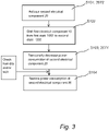
- the controller 30 is configured to in step S101 activate the second electrical element 20 for a predetermined time period 20T2 before it is contemplated to shift the first electrical component 10 from the first state 10S1 to the second state 10S2.
- This activation may be a specific activation provided in response to a contemplated shift.
- the specific activation may alternatively be dispensed with in case it is known that there is already an electrical component running with a power consumption sufficient for that electrical component to heat a second portion 220 such that the power consumption could be decreased, and such that the electrical component in question could act as said second electrical component 20.
- this activation of the second electrical element 20 for a predetermined time period 20T2 before it is contemplated to shift the first electrical component 10 from the first state 10S1 to the second state 10S2 may be referred to as a pre-heating of the second portion 220.
- step S102 the first electrical component 10, such as the IR LED element 13, is shifted from an off-state 10S1 to an on-state 10S2.
- step S103 electrical power consumption of the second electrical component 20, such as the step motor 21, the heater 22 or the resistor 24 close to the moisture absorption element 40, is temporarily decreased.
- One way of controlling the camera is to provide the decrease in power consumption of the second electrical component 20 in response to the shift in state of the first electrical component 10.
- the decrease S103 must be provided after the shift S102; it is, e.g., conceivable that the electronic circuitry, such as the controller 30, of the camera 1 may form a decision of a forthcoming shift in state of the first electrical component 10 and that the power consumption of the second electrical component 20 is decreased in response to this decision such that the temperature of the second electrical component 20 has begun to slightly decrease at the point in time when the shift in state of the first electrical component is actually performed.
- steps S102 and S103 may be the reversed compared to the one indicated in figure 3 .
- the timing does not need to be exactly the same, or the order need to be in a specific order, there should be a simultaneity such that the decrease in temperature of the second electrical component 20 counteracts the increase in absolute humidity induced by the first electrical component 10.
- step S104 After a predetermined time period 20T1 has passed or in response to a predetermined humidity condition HC being fulfilled, the electrical power consumption of the second electrical component 20 is once again restored in step S104, i.e. the power consumption is restored to as it was before the decrease of step S103.
- the humidity condition HC is typically related to the relative humidity in the air 2a. It should be noted that this step S104 may be dispensed with in case the other functionalities of the camera 1 does not necessitate this step.
- the second electrical component 20 is a heater 22 or resistor 24 which is activated as a specific pre-heating step for a predetermined time period 20T2 before it is contemplated to shift the first electrical component 10 from the first state 10S1 to the second state 10S2.
- the step S104 is dispensed with and the second electrical component 20 is not activated until it is anew contemplated to provide a new shift in state of the first electrical component 10.
- the heater 22 or resistor 24 is activated at a predetermined time, in the order of one or two hours, before dusk such that the second portion 220 or moisture absorption element 40 is pre-heated and ready to be cooled.
- the heater 22 or resistor 24 is shut down and the second portion 220 or moisture absorption element 40 act as a moisture trap and absorbs the water molecules desorbed by the first portion 210 nearby the IR LED element 13.
- dawn the IR LED element 13 is shifted to an off-state.
- the first electrical component 10 is preferably selected from a group consisting of: an electrical motor 21, such as an electrical step motor, a heater 22, a lighting element 13, such as an IR LED element, and a resistor 24.
- the inventive concept addresses the case where the second state 10S2 is associated with an increase in heat dissipation from the first electrical component 10 compared to heat dissipation from the first electrical component 10 in the first state 10S1.
- the second electrical component 20 is preferably selected from a group consisting of: an electrical motor 21, such as an electrical step motor, a heater 22, and a resistor 24.
Landscapes
- Engineering & Computer Science (AREA)
- Physics & Mathematics (AREA)
- Multimedia (AREA)
- Signal Processing (AREA)
- General Physics & Mathematics (AREA)
- Aviation & Aerospace Engineering (AREA)
- Electromagnetism (AREA)
- Human Computer Interaction (AREA)
- Optics & Photonics (AREA)
- Studio Devices (AREA)
- Camera Bodies And Camera Details Or Accessories (AREA)
- Cameras Adapted For Combination With Other Photographic Or Optical Apparatuses (AREA)
Priority Applications (6)
| Application Number | Priority Date | Filing Date | Title |
|---|---|---|---|
| EP20183955.2A EP3934226B1 (en) | 2020-07-03 | 2020-07-03 | A camera and a method |
| US17/325,369 US11363173B2 (en) | 2020-07-03 | 2021-05-20 | Camera and a method |
| TW110121873A TW202202931A (zh) | 2020-07-03 | 2021-06-16 | 攝像機及方法 |
| JP2021106255A JP7578550B2 (ja) | 2020-07-03 | 2021-06-28 | カメラおよび方法 |
| CN202110718122.4A CN113965672B (zh) | 2020-07-03 | 2021-06-28 | 摄像机和方法 |
| KR1020210085031A KR102759121B1 (ko) | 2020-07-03 | 2021-06-29 | 카메라와 방법 |
Applications Claiming Priority (1)
| Application Number | Priority Date | Filing Date | Title |
|---|---|---|---|
| EP20183955.2A EP3934226B1 (en) | 2020-07-03 | 2020-07-03 | A camera and a method |
Publications (2)
| Publication Number | Publication Date |
|---|---|
| EP3934226A1 EP3934226A1 (en) | 2022-01-05 |
| EP3934226B1 true EP3934226B1 (en) | 2022-06-22 |
Family
ID=71514934
Family Applications (1)
| Application Number | Title | Priority Date | Filing Date |
|---|---|---|---|
| EP20183955.2A Active EP3934226B1 (en) | 2020-07-03 | 2020-07-03 | A camera and a method |
Country Status (6)
| Country | Link |
|---|---|
| US (1) | US11363173B2 (enExample) |
| EP (1) | EP3934226B1 (enExample) |
| JP (1) | JP7578550B2 (enExample) |
| KR (1) | KR102759121B1 (enExample) |
| CN (1) | CN113965672B (enExample) |
| TW (1) | TW202202931A (enExample) |
Families Citing this family (2)
| Publication number | Priority date | Publication date | Assignee | Title |
|---|---|---|---|---|
| USD982646S1 (en) * | 2020-11-19 | 2023-04-04 | Anker Innovations Technology Co., Ltd. | Camera |
| CN116125733B (zh) * | 2022-08-30 | 2025-11-07 | 合肥中科君达视界技术股份有限公司 | 耐受高低温冲击的内部温度自动调节装置 |
Family Cites Families (6)
| Publication number | Priority date | Publication date | Assignee | Title |
|---|---|---|---|---|
| KR101608729B1 (ko) * | 2009-10-01 | 2016-04-20 | 삼성전자주식회사 | 이미지 센서 모듈, 이의 제조방법, 이미지 센서 모듈을 구비하는 촬상소자 및 이의 제조방법 |
| ITMI20121589A1 (it) * | 2012-09-24 | 2014-03-25 | Videotec Spa | Custodia perfezionata per videocamera di sorveglianza e dispositivo di supporto per una custodia per videocamera di sorveglianza |
| US9420178B2 (en) * | 2013-12-20 | 2016-08-16 | Qualcomm Incorporated | Thermal and power management |
| CN104219433A (zh) * | 2014-09-17 | 2014-12-17 | 深圳英飞拓科技股份有限公司 | 一种监控摄像装置及其降温除湿方法 |
| JP6595199B2 (ja) * | 2015-04-08 | 2019-10-23 | シャープ株式会社 | 調湿装置 |
| EP3553769B1 (en) * | 2018-04-10 | 2020-06-03 | Axis AB | A camera assembly having a cooling arrangement |
-
2020
- 2020-07-03 EP EP20183955.2A patent/EP3934226B1/en active Active
-
2021
- 2021-05-20 US US17/325,369 patent/US11363173B2/en active Active
- 2021-06-16 TW TW110121873A patent/TW202202931A/zh unknown
- 2021-06-28 CN CN202110718122.4A patent/CN113965672B/zh active Active
- 2021-06-28 JP JP2021106255A patent/JP7578550B2/ja active Active
- 2021-06-29 KR KR1020210085031A patent/KR102759121B1/ko active Active
Also Published As
| Publication number | Publication date |
|---|---|
| TW202202931A (zh) | 2022-01-16 |
| JP2022013805A (ja) | 2022-01-18 |
| CN113965672B (zh) | 2024-07-09 |
| KR102759121B1 (ko) | 2025-01-23 |
| KR20220004561A (ko) | 2022-01-11 |
| US20220006961A1 (en) | 2022-01-06 |
| CN113965672A (zh) | 2022-01-21 |
| US11363173B2 (en) | 2022-06-14 |
| JP7578550B2 (ja) | 2024-11-06 |
| EP3934226A1 (en) | 2022-01-05 |
Similar Documents
| Publication | Publication Date | Title |
|---|---|---|
| US11363173B2 (en) | Camera and a method | |
| CN111447704B (zh) | 防凝露装置、拍摄设备以及防凝露方法 | |
| US20110151765A1 (en) | Operating condition adjusting system and method of portable data center | |
| US20120190292A1 (en) | Enclosure and method of cooling same using ambient air | |
| JP2016127624A (ja) | 電気機器収納用キャビネット | |
| AU2021320493B2 (en) | Lens heater assembly | |
| JP2004101154A (ja) | 空気調和機の運転方法及び空気調和機 | |
| TWI822224B (zh) | 攝影裝置、攝影裝置加熱模組與方法 | |
| JP2005236099A (ja) | 電子装置筐体の保温方法及びそれを適用した電子装置収納型熱交換構造体 | |
| JP7438277B2 (ja) | 霜取りレンズ装置 | |
| EP0535531A1 (en) | Thermo-switch apparatus | |
| CN103974602B (zh) | 冷却组件 | |
| JPH0983167A (ja) | 屋外設置電子装置筐体 | |
| KR102247310B1 (ko) | 복합 방열 구조체 및 이를 포함하는 스마트 구조물 | |
| WO2006025688A1 (en) | Cooling device for computer using thermoelectric element | |
| JP2022013805A5 (enExample) | ||
| US9722514B2 (en) | Motor drive and method of controlling a temperature of a motor drive | |
| US5615829A (en) | Air conditioning system thermostat having adjustable cycling rate | |
| US20160123627A1 (en) | Heating appliance comprising a phase-change material | |
| KR101779481B1 (ko) | 자동차 공조장치의 블로워모터 제어장치 | |
| JP2002277954A (ja) | カメラハウジング | |
| WO2025210864A1 (ja) | 空気調和機、及び制御方法 | |
| JP2025119650A (ja) | 制御装置および空気調和装置 | |
| US20020015286A1 (en) | Temperature regulation apparatus for electrical box | |
| CN117190463A (zh) | 电控箱及其温度控制方法、控制装置、空调设备 |
Legal Events
| Date | Code | Title | Description |
|---|---|---|---|
| STAA | Information on the status of an ep patent application or granted ep patent |
Free format text: STATUS: UNKNOWN |
|
| PUAI | Public reference made under article 153(3) epc to a published international application that has entered the european phase |
Free format text: ORIGINAL CODE: 0009012 |
|
| STAA | Information on the status of an ep patent application or granted ep patent |
Free format text: STATUS: REQUEST FOR EXAMINATION WAS MADE |
|
| 17P | Request for examination filed |
Effective date: 20210108 |
|
| AK | Designated contracting states |
Kind code of ref document: A1 Designated state(s): AL AT BE BG CH CY CZ DE DK EE ES FI FR GB GR HR HU IE IS IT LI LT LU LV MC MK MT NL NO PL PT RO RS SE SI SK SM TR |
|
| B565 | Issuance of search results under rule 164(2) epc |
Effective date: 20201130 |
|
| RIC1 | Information provided on ipc code assigned before grant |
Ipc: G03B 37/04 20210101ALI20220221BHEP Ipc: G05D 27/02 20060101ALI20220221BHEP Ipc: G03B 17/55 20210101ALI20220221BHEP Ipc: G05D 22/02 20060101ALI20220221BHEP Ipc: H04N 5/232 20060101ALI20220221BHEP Ipc: H04N 5/225 20060101AFI20220221BHEP |
|
| GRAP | Despatch of communication of intention to grant a patent |
Free format text: ORIGINAL CODE: EPIDOSNIGR1 |
|
| STAA | Information on the status of an ep patent application or granted ep patent |
Free format text: STATUS: GRANT OF PATENT IS INTENDED |
|
| INTG | Intention to grant announced |
Effective date: 20220401 |
|
| GRAS | Grant fee paid |
Free format text: ORIGINAL CODE: EPIDOSNIGR3 |
|
| GRAA | (expected) grant |
Free format text: ORIGINAL CODE: 0009210 |
|
| STAA | Information on the status of an ep patent application or granted ep patent |
Free format text: STATUS: THE PATENT HAS BEEN GRANTED |
|
| AK | Designated contracting states |
Kind code of ref document: B1 Designated state(s): AL AT BE BG CH CY CZ DE DK EE ES FI FR GB GR HR HU IE IS IT LI LT LU LV MC MK MT NL NO PL PT RO RS SE SI SK SM TR |
|
| REG | Reference to a national code |
Ref country code: GB Ref legal event code: FG4D |
|
| REG | Reference to a national code |
Ref country code: CH Ref legal event code: EP |
|
| REG | Reference to a national code |
Ref country code: DE Ref legal event code: R096 Ref document number: 602020003631 Country of ref document: DE |
|
| REG | Reference to a national code |
Ref country code: AT Ref legal event code: REF Ref document number: 1500558 Country of ref document: AT Kind code of ref document: T Effective date: 20220715 |
|
| REG | Reference to a national code |
Ref country code: IE Ref legal event code: FG4D |
|
| REG | Reference to a national code |
Ref country code: SE Ref legal event code: TRGR |
|
| REG | Reference to a national code |
Ref country code: LT Ref legal event code: MG9D |
|
| REG | Reference to a national code |
Ref country code: NL Ref legal event code: MP Effective date: 20220622 |
|
| PG25 | Lapsed in a contracting state [announced via postgrant information from national office to epo] |
Ref country code: NO Free format text: LAPSE BECAUSE OF FAILURE TO SUBMIT A TRANSLATION OF THE DESCRIPTION OR TO PAY THE FEE WITHIN THE PRESCRIBED TIME-LIMIT Effective date: 20220922 Ref country code: LT Free format text: LAPSE BECAUSE OF FAILURE TO SUBMIT A TRANSLATION OF THE DESCRIPTION OR TO PAY THE FEE WITHIN THE PRESCRIBED TIME-LIMIT Effective date: 20220622 Ref country code: HR Free format text: LAPSE BECAUSE OF FAILURE TO SUBMIT A TRANSLATION OF THE DESCRIPTION OR TO PAY THE FEE WITHIN THE PRESCRIBED TIME-LIMIT Effective date: 20220622 Ref country code: GR Free format text: LAPSE BECAUSE OF FAILURE TO SUBMIT A TRANSLATION OF THE DESCRIPTION OR TO PAY THE FEE WITHIN THE PRESCRIBED TIME-LIMIT Effective date: 20220923 Ref country code: FI Free format text: LAPSE BECAUSE OF FAILURE TO SUBMIT A TRANSLATION OF THE DESCRIPTION OR TO PAY THE FEE WITHIN THE PRESCRIBED TIME-LIMIT Effective date: 20220622 Ref country code: BG Free format text: LAPSE BECAUSE OF FAILURE TO SUBMIT A TRANSLATION OF THE DESCRIPTION OR TO PAY THE FEE WITHIN THE PRESCRIBED TIME-LIMIT Effective date: 20220922 |
|
| REG | Reference to a national code |
Ref country code: AT Ref legal event code: MK05 Ref document number: 1500558 Country of ref document: AT Kind code of ref document: T Effective date: 20220622 |
|
| REG | Reference to a national code |
Ref country code: DE Ref legal event code: R079 Ref document number: 602020003631 Country of ref document: DE Free format text: PREVIOUS MAIN CLASS: H04N0005225000 Ipc: H04N0023000000 |
|
| PG25 | Lapsed in a contracting state [announced via postgrant information from national office to epo] |
Ref country code: RS Free format text: LAPSE BECAUSE OF FAILURE TO SUBMIT A TRANSLATION OF THE DESCRIPTION OR TO PAY THE FEE WITHIN THE PRESCRIBED TIME-LIMIT Effective date: 20220622 Ref country code: LV Free format text: LAPSE BECAUSE OF FAILURE TO SUBMIT A TRANSLATION OF THE DESCRIPTION OR TO PAY THE FEE WITHIN THE PRESCRIBED TIME-LIMIT Effective date: 20220622 |
|
| PG25 | Lapsed in a contracting state [announced via postgrant information from national office to epo] |
Ref country code: NL Free format text: LAPSE BECAUSE OF FAILURE TO SUBMIT A TRANSLATION OF THE DESCRIPTION OR TO PAY THE FEE WITHIN THE PRESCRIBED TIME-LIMIT Effective date: 20220622 |
|
| PG25 | Lapsed in a contracting state [announced via postgrant information from national office to epo] |
Ref country code: SM Free format text: LAPSE BECAUSE OF FAILURE TO SUBMIT A TRANSLATION OF THE DESCRIPTION OR TO PAY THE FEE WITHIN THE PRESCRIBED TIME-LIMIT Effective date: 20220622 Ref country code: SK Free format text: LAPSE BECAUSE OF FAILURE TO SUBMIT A TRANSLATION OF THE DESCRIPTION OR TO PAY THE FEE WITHIN THE PRESCRIBED TIME-LIMIT Effective date: 20220622 Ref country code: RO Free format text: LAPSE BECAUSE OF FAILURE TO SUBMIT A TRANSLATION OF THE DESCRIPTION OR TO PAY THE FEE WITHIN THE PRESCRIBED TIME-LIMIT Effective date: 20220622 Ref country code: PT Free format text: LAPSE BECAUSE OF FAILURE TO SUBMIT A TRANSLATION OF THE DESCRIPTION OR TO PAY THE FEE WITHIN THE PRESCRIBED TIME-LIMIT Effective date: 20221024 Ref country code: ES Free format text: LAPSE BECAUSE OF FAILURE TO SUBMIT A TRANSLATION OF THE DESCRIPTION OR TO PAY THE FEE WITHIN THE PRESCRIBED TIME-LIMIT Effective date: 20220622 Ref country code: EE Free format text: LAPSE BECAUSE OF FAILURE TO SUBMIT A TRANSLATION OF THE DESCRIPTION OR TO PAY THE FEE WITHIN THE PRESCRIBED TIME-LIMIT Effective date: 20220622 Ref country code: CZ Free format text: LAPSE BECAUSE OF FAILURE TO SUBMIT A TRANSLATION OF THE DESCRIPTION OR TO PAY THE FEE WITHIN THE PRESCRIBED TIME-LIMIT Effective date: 20220622 Ref country code: AT Free format text: LAPSE BECAUSE OF FAILURE TO SUBMIT A TRANSLATION OF THE DESCRIPTION OR TO PAY THE FEE WITHIN THE PRESCRIBED TIME-LIMIT Effective date: 20220622 |
|
| PG25 | Lapsed in a contracting state [announced via postgrant information from national office to epo] |
Ref country code: PL Free format text: LAPSE BECAUSE OF FAILURE TO SUBMIT A TRANSLATION OF THE DESCRIPTION OR TO PAY THE FEE WITHIN THE PRESCRIBED TIME-LIMIT Effective date: 20220622 Ref country code: IS Free format text: LAPSE BECAUSE OF FAILURE TO SUBMIT A TRANSLATION OF THE DESCRIPTION OR TO PAY THE FEE WITHIN THE PRESCRIBED TIME-LIMIT Effective date: 20221022 |
|
| REG | Reference to a national code |
Ref country code: DE Ref legal event code: R097 Ref document number: 602020003631 Country of ref document: DE |
|
| REG | Reference to a national code |
Ref country code: BE Ref legal event code: MM Effective date: 20220731 |
|
| PG25 | Lapsed in a contracting state [announced via postgrant information from national office to epo] |
Ref country code: MC Free format text: LAPSE BECAUSE OF FAILURE TO SUBMIT A TRANSLATION OF THE DESCRIPTION OR TO PAY THE FEE WITHIN THE PRESCRIBED TIME-LIMIT Effective date: 20220622 Ref country code: AL Free format text: LAPSE BECAUSE OF FAILURE TO SUBMIT A TRANSLATION OF THE DESCRIPTION OR TO PAY THE FEE WITHIN THE PRESCRIBED TIME-LIMIT Effective date: 20220622 |
|
| PG25 | Lapsed in a contracting state [announced via postgrant information from national office to epo] |
Ref country code: LU Free format text: LAPSE BECAUSE OF NON-PAYMENT OF DUE FEES Effective date: 20220703 Ref country code: DK Free format text: LAPSE BECAUSE OF FAILURE TO SUBMIT A TRANSLATION OF THE DESCRIPTION OR TO PAY THE FEE WITHIN THE PRESCRIBED TIME-LIMIT Effective date: 20220622 |
|
| PLBE | No opposition filed within time limit |
Free format text: ORIGINAL CODE: 0009261 |
|
| STAA | Information on the status of an ep patent application or granted ep patent |
Free format text: STATUS: NO OPPOSITION FILED WITHIN TIME LIMIT |
|
| 26N | No opposition filed |
Effective date: 20230323 |
|
| PG25 | Lapsed in a contracting state [announced via postgrant information from national office to epo] |
Ref country code: BE Free format text: LAPSE BECAUSE OF NON-PAYMENT OF DUE FEES Effective date: 20220731 |
|
| P01 | Opt-out of the competence of the unified patent court (upc) registered |
Effective date: 20230505 |
|
| PG25 | Lapsed in a contracting state [announced via postgrant information from national office to epo] |
Ref country code: IE Free format text: LAPSE BECAUSE OF NON-PAYMENT OF DUE FEES Effective date: 20220703 |
|
| PG25 | Lapsed in a contracting state [announced via postgrant information from national office to epo] |
Ref country code: IT Free format text: LAPSE BECAUSE OF FAILURE TO SUBMIT A TRANSLATION OF THE DESCRIPTION OR TO PAY THE FEE WITHIN THE PRESCRIBED TIME-LIMIT Effective date: 20220622 |
|
| REG | Reference to a national code |
Ref country code: CH Ref legal event code: PL |
|
| PG25 | Lapsed in a contracting state [announced via postgrant information from national office to epo] |
Ref country code: MK Free format text: LAPSE BECAUSE OF FAILURE TO SUBMIT A TRANSLATION OF THE DESCRIPTION OR TO PAY THE FEE WITHIN THE PRESCRIBED TIME-LIMIT Effective date: 20220622 Ref country code: CY Free format text: LAPSE BECAUSE OF FAILURE TO SUBMIT A TRANSLATION OF THE DESCRIPTION OR TO PAY THE FEE WITHIN THE PRESCRIBED TIME-LIMIT Effective date: 20220622 Ref country code: CH Free format text: LAPSE BECAUSE OF NON-PAYMENT OF DUE FEES Effective date: 20230731 |
|
| PG25 | Lapsed in a contracting state [announced via postgrant information from national office to epo] |
Ref country code: HU Free format text: LAPSE BECAUSE OF FAILURE TO SUBMIT A TRANSLATION OF THE DESCRIPTION OR TO PAY THE FEE WITHIN THE PRESCRIBED TIME-LIMIT; INVALID AB INITIO Effective date: 20200703 |
|
| PG25 | Lapsed in a contracting state [announced via postgrant information from national office to epo] |
Ref country code: TR Free format text: LAPSE BECAUSE OF FAILURE TO SUBMIT A TRANSLATION OF THE DESCRIPTION OR TO PAY THE FEE WITHIN THE PRESCRIBED TIME-LIMIT Effective date: 20220622 |
|
| PG25 | Lapsed in a contracting state [announced via postgrant information from national office to epo] |
Ref country code: MT Free format text: LAPSE BECAUSE OF FAILURE TO SUBMIT A TRANSLATION OF THE DESCRIPTION OR TO PAY THE FEE WITHIN THE PRESCRIBED TIME-LIMIT Effective date: 20220622 |
|
| PG25 | Lapsed in a contracting state [announced via postgrant information from national office to epo] |
Ref country code: BG Free format text: LAPSE BECAUSE OF FAILURE TO SUBMIT A TRANSLATION OF THE DESCRIPTION OR TO PAY THE FEE WITHIN THE PRESCRIBED TIME-LIMIT Effective date: 20220622 |
|
| PG25 | Lapsed in a contracting state [announced via postgrant information from national office to epo] |
Ref country code: BG Free format text: LAPSE BECAUSE OF FAILURE TO SUBMIT A TRANSLATION OF THE DESCRIPTION OR TO PAY THE FEE WITHIN THE PRESCRIBED TIME-LIMIT Effective date: 20220622 |
|
| PGFP | Annual fee paid to national office [announced via postgrant information from national office to epo] |
Ref country code: GB Payment date: 20250619 Year of fee payment: 6 |
|
| PGFP | Annual fee paid to national office [announced via postgrant information from national office to epo] |
Ref country code: FR Payment date: 20250620 Year of fee payment: 6 |
|
| PGFP | Annual fee paid to national office [announced via postgrant information from national office to epo] |
Ref country code: SE Payment date: 20250619 Year of fee payment: 6 |
|
| PGFP | Annual fee paid to national office [announced via postgrant information from national office to epo] |
Ref country code: DE Payment date: 20250620 Year of fee payment: 6 |