EP3553769B1 - A camera assembly having a cooling arrangement - Google Patents
A camera assembly having a cooling arrangement Download PDFInfo
- Publication number
- EP3553769B1 EP3553769B1 EP18166589.4A EP18166589A EP3553769B1 EP 3553769 B1 EP3553769 B1 EP 3553769B1 EP 18166589 A EP18166589 A EP 18166589A EP 3553769 B1 EP3553769 B1 EP 3553769B1
- Authority
- EP
- European Patent Office
- Prior art keywords
- camera assembly
- heat dissipation
- dissipation portion
- camera
- channel
- Prior art date
- Legal status (The legal status is an assumption and is not a legal conclusion. Google has not performed a legal analysis and makes no representation as to the accuracy of the status listed.)
- Active
Links
Images
Classifications
-
- G—PHYSICS
- G09—EDUCATION; CRYPTOGRAPHY; DISPLAY; ADVERTISING; SEALS
- G09G—ARRANGEMENTS OR CIRCUITS FOR CONTROL OF INDICATING DEVICES USING STATIC MEANS TO PRESENT VARIABLE INFORMATION
- G09G5/00—Control arrangements or circuits for visual indicators common to cathode-ray tube indicators and other visual indicators
-
- G—PHYSICS
- G03—PHOTOGRAPHY; CINEMATOGRAPHY; ANALOGOUS TECHNIQUES USING WAVES OTHER THAN OPTICAL WAVES; ELECTROGRAPHY; HOLOGRAPHY
- G03B—APPARATUS OR ARRANGEMENTS FOR TAKING PHOTOGRAPHS OR FOR PROJECTING OR VIEWING THEM; APPARATUS OR ARRANGEMENTS EMPLOYING ANALOGOUS TECHNIQUES USING WAVES OTHER THAN OPTICAL WAVES; ACCESSORIES THEREFOR
- G03B17/00—Details of cameras or camera bodies; Accessories therefor
- G03B17/02—Bodies
-
- G—PHYSICS
- G03—PHOTOGRAPHY; CINEMATOGRAPHY; ANALOGOUS TECHNIQUES USING WAVES OTHER THAN OPTICAL WAVES; ELECTROGRAPHY; HOLOGRAPHY
- G03B—APPARATUS OR ARRANGEMENTS FOR TAKING PHOTOGRAPHS OR FOR PROJECTING OR VIEWING THEM; APPARATUS OR ARRANGEMENTS EMPLOYING ANALOGOUS TECHNIQUES USING WAVES OTHER THAN OPTICAL WAVES; ACCESSORIES THEREFOR
- G03B17/00—Details of cameras or camera bodies; Accessories therefor
- G03B17/55—Details of cameras or camera bodies; Accessories therefor with provision for heating or cooling, e.g. in aircraft
-
- H—ELECTRICITY
- H04—ELECTRIC COMMUNICATION TECHNIQUE
- H04N—PICTORIAL COMMUNICATION, e.g. TELEVISION
- H04N23/00—Cameras or camera modules comprising electronic image sensors; Control thereof
- H04N23/45—Cameras or camera modules comprising electronic image sensors; Control thereof for generating image signals from two or more image sensors being of different type or operating in different modes, e.g. with a CMOS sensor for moving images in combination with a charge-coupled device [CCD] for still images
-
- H—ELECTRICITY
- H04—ELECTRIC COMMUNICATION TECHNIQUE
- H04N—PICTORIAL COMMUNICATION, e.g. TELEVISION
- H04N23/00—Cameras or camera modules comprising electronic image sensors; Control thereof
- H04N23/50—Constructional details
-
- H—ELECTRICITY
- H04—ELECTRIC COMMUNICATION TECHNIQUE
- H04N—PICTORIAL COMMUNICATION, e.g. TELEVISION
- H04N23/00—Cameras or camera modules comprising electronic image sensors; Control thereof
- H04N23/50—Constructional details
- H04N23/51—Housings
-
- G—PHYSICS
- G03—PHOTOGRAPHY; CINEMATOGRAPHY; ANALOGOUS TECHNIQUES USING WAVES OTHER THAN OPTICAL WAVES; ELECTROGRAPHY; HOLOGRAPHY
- G03B—APPARATUS OR ARRANGEMENTS FOR TAKING PHOTOGRAPHS OR FOR PROJECTING OR VIEWING THEM; APPARATUS OR ARRANGEMENTS EMPLOYING ANALOGOUS TECHNIQUES USING WAVES OTHER THAN OPTICAL WAVES; ACCESSORIES THEREFOR
- G03B2217/00—Details of cameras or camera bodies; Accessories therefor
- G03B2217/002—Details of arrangement of components in or on camera body
Definitions
- the present invention relates to a camera assembly and in particular a camera assembly having a cooling arrangement.
- Such protective housing typically comprises a chassis in which the electronics and camera heads are arranged, and transparent portion, such as a dome or window.
- transparent portion such as a dome or window.
- the purpose of the transparent portion is of course to allow transmission of radiation of interest for sensors of the camera head or camera heads, and as such the properties may be altered (by choice of materials or coatings) depending on the desired transmission properties.
- the properties of the housing may vary depending on intended use, ranging from a dust protection to various IP-classifications, explosion protection, etc. There are numerous examples of such housings, provided separately or as a designated part of a camera assembly, commercially available.
- the housing An effect of the housing is that the camera head(s) will be located in a confined space, and that the heat generated during operation will be confined as well. Excessive heat is a feature that is to be avoided when operating imaging sensors, e.g. CMOS sensors, since it will result in an increase in the noise generated by the system.
- the thermal noise is a white noise that affects all frequencies and all pixels of the imaging system, and as such it will obscure the signal of interest, which in an imaging situation may correspond to finer details in a field of view of the camera head. Thermal noise will always affect the image in a detrimental way, yet it becomes increasingly negative as the overall signal decreases, e.g. during imaging in low-light situations.
- WO2015063890A1 a portable remote monitor camera constructed from a web camera and a router device both arranged in a fan-ventilated housing are disclosed.
- JP9172564A discloses a monitor camera equipment of dome type relying on convection for maintaining a cooling air flow.
- a through-hole is arranged in a surface of the equipment adapted to face a ceiling surface, the purpose being to lead the cooling air into the ceiling to which the camera equipment is arranged.
- document WO2005048586A1 discloses a camera device for 360-degree panorama shots, housing multiple cameras within the same transparent dome.
- a fan arranged on a fixing base plate forces external air to the internal portion of the camera device for transfer of heat from heated components.
- the actual airflow is however not readily deduced from the disclosure of this document.
- the present invention aims at providing an improved cooling arrangement, tailormade for a specific group of camera assemblies.
- the present invention aims at providing a camera assembly comprising an improved cooling arrangement.
- the camera assembly has a housing, a transparent dome, and it is configured to receive at least one camera head arranged in the housing, inside the transparent dome.
- the housing comprises a cooling arrangement having a heat dissipation portion arranged within the housing and extending through the dome, wherein the heat dissipation portion is made from a material configured to transfer heat efficiently, and wherein the cooling arrangement comprises a channel for airflow. Capturing the generated heat inside the camera assembly and efficiently transferring it to an airflow leading out from the assembly enables an efficient cooling and an increased flexibility in the design of the assembly. It also enables for the heat dissipation portion to be a structural part of the assembly, and in that way the number of components may be minimized.
- the heat dissipation portion also constitutes a physical barrier between the channel and a compartment where said at least one camera head is arranged. This means that any interfaces between other components should be adequately sealed.
- the heat dissipation portion in one or several embodiments of the present invention. extends to a chassis of the housing, to enable, e.g., a rigid construction, beneficial heat conduction properties and an adequate seal to the camera compartment.
- the channel may extend to or through the chassis, and continue as a manifold extending outwards towards a perimeter of the housing.
- the design of the manifold may be such that it directs the flow of air over surfaces expected to be heated by heat-generating components.
- chassis may be made from a material configured to transfer heat efficiently.
- the heat dissipation portion may comprise a fitting for a processing unit of the camera assembly.
- the processing unit may be in direct contact with the very component used for dissipating the generated heat.
- a fan may arranged in the heat dissipation portion in order to enhance the airflow.
- the fan is preferably powered directly from a power unit of the camera assembly, yet another power source may be utilized as well.
- the fan may be used to enhance the convective flow being generated by the heated air, yet it may also be used to reverse the direction of the air flow. This may be preferential in some applications where an airflow in the vicinity of the dome is not desired.
- the inlet of the channel may be arranged at a center of the camera assembly, and wherein an outlet of the channel may be arranged at a perimeter of the assembly.
- “Inlet” and “outlet” refers to the normal, or expected, flow direction. The flow could be reversed, either by natural causes, such as a strong draft or an unexpected temperature profile in the channel, or by the use of a fan. In that sense the "inlet” and “outlet” may instead be referred to as a first and a second opening of the channel, yet inlet and outlet are considered to cover most applications.
- an exchangeable filter unit may be arranged near an inlet of the channel.
- the upper part of the heat dissipation portion at an end of the heat dissipation portion extending through the dome, may be removable for access to the interior of the heat dissipation portion.
- the exchangeable filter may be a component requiring periodical replacement it could be preferable to simplify the access to the filter even more. This may be accomplished if the removable upper part of the heat dissipation portion comprises a cap below which the removable filter may be arranged.
- the cap may be pressed into place, or it may comprise an exterior threading fitting matingly with a threading of an opening in the removable upper part.
- the removable upper part may be held in place towards the rest of the heat dissipation portion by means of a pressure exerted by the dome.
- Another inventive concept relates to a camera assembly of the disclosed type, comprising multiple camera heads, such as 2, 3, 4, 5, or more.
- a camera assembly 100 in which the present invention may be embodied, is illustrated in the perspective view of Fig. 1 .
- the camera assembly 100 comprises a housing 102, one or more camera heads 104, and a transparent dome 106.
- a similar version of such a camera assembly is disclosed in EP2887328 , by the present applicant.
- a central part 108 of the assembly may comprise connectors, control units etc. (not shown), for receiving, processing and forwarding the result of the imaging effected by the camera heads 104.
- the central part 108 will in this embodiment comprise the cooling arrangement, or at least a portion thereof, and we will return to that.
- each of the individually mentioned portions may in fact comprise several parts, e.g. the "housing 102" may comprise a base, a chassis, a bracket, several covers etc. Furthermore, these parts may be manufactured from different materials (or the same material).
- the camera assembly 100 is basically upside-down as compared to a normal installation where the camera assembly is attached to a ceiling or mounting base with the camera heads 104 facing down and to the sides to surveil a designated area.
- the most prominent part is the heat dissipation portion 110 extending essentially from a top to a bottom of the camera assembly 100.
- the heat dissipation portion provides a physical barrier between a compartment configured to house the camera head(s) and a channel 112 extending through the heat dissipation portion.
- the heat dissipation portion has a flange or surface for receiving a seal configured to seal off the contact area between the dome 104 and the heat dissipation portion. Further constructional details may be involved in the seal arrangement 114.
- the heat dissipation portion is made from a material with good properties in regard of heat conduction, such that it transports heat efficiently. It may also be noted that the heat dissipation portion is a structural part of the camera assembly, adding to its functionality.
- heat dissipation portion should be coated, using electro deposition is preferred over e.g., powder coating in order to maintain the thermal conductivity.
- powder coating or other surface treatments may be conceivable depending on the application.
- the properties of transporting heat efficiently could also be provided in a more elaborate manner, which also would be acceptable from a functional viewpoint, though such a more elaborate solution would be likely to incorporate a higher cost.
- Such more elaborate solutions could correspond to using heat pipes.
- a more low-tech solution is to use a material having a higher thermal conductivity, such as copper, which would have an effect on cost of the device.
- parts may be manufactured from different materials (or the same material) depending on the desired properties.
- Parts that should have increased rigidity or heat conducting properties could be made of, e.g., aluminum.
- Suitable processes for applying a color to such parts may be powder coating or electro deposition, as already mentioned.
- Other parts may be made from colored plastics, and the transparent dome may be made from, e.g., acrylic or polycarbonate.
- the physical barrier provided allows for outside air to access the channel without any direct impact on the camera head compartment.
- the heat dissipation portion 110 is attached to the housing at the chassis 116, and the channel 112 extends into a manifold 118 between the chassis 116 and the bracket 120 of the housing 102.
- the manifold 118 extends to peripheral edges of the housing, and exits through an outlet arrangement 122 provided in the housing. As such, the outlet arrangement will result in a flow of air over some surfaces of the dome, which may reduce contamination from the surrounding air, in particular if the air used for cooling is filtered.
- the outlet is embodied as a vent arrangement 122, yet the shape, size and position of the outlet may vary with application.
- the outlets suggestively in the form of a vent grid, could be arranged closer to the base of the housing, i.e. more remote from the inlet (to be described later), in order to increase convection.
- the shape of the manifold 118 may vary, yet one design feature may be that it should pass as close as possible to heat-generating components of the camera assembly. Concentrating the cooling air flow such that it passes an area where the most heat is generated would be considered suitable.
- heat-generating components may be arranged in direct physical contact with the heat dissipation portion 110, which is the case for the processor indicated at 124.
- the cooling arrangement also comprises an inlet 126, and for the present embodiment the inlet is arranged in the center of the camera assembly, but more importantly it guides an airflow directly into the heat dissipation portion 110 and the channel 112 where it may serve its purpose of transporting heat away from the heat dissipation portion.
- the interior of the heat dissipation portion may also comprise cooling flanges 128, serving the purpose of increasing the contact area between the channel walls and the flow of air, in a per se known manner.
- a filter 132 may be arranged in the airflow through the channel.
- a filter may be arranged by removing a cap 136 of the inlet (with a screwdriver or by turning the cap manually), arranging a filter that fits in a filter holder, and putting the cap back on again.
- the filter should obviously have a shape that conforms to the portion of the channel in which it is arranged, which in the present case results in that the filter 132 will have a cylindrical shape, a sectional view of which is shown in Fig. 4 .
- a fan 134 may be arranged in the channel.
- the purpose of the fan is to increase the airflow and in that way to increase the heat transfer further.
- the fan is merely illustrated as a propeller in Fig. 4 , and in a real embodiment the fan could be provided in the form of a duct fan that is insertable in the channel and which is powered from the power unit of the camera.
- the choice of fan may vary with several factors, such as the amount of power available and a desired cooling efficiency.
- the fan could assist in maintaining the dome free from dust and debris, as mentioned in relation to the discussion about the outlets 122, or even be used to de-ice or dry the exterior of the dome by blowing the (now preheated) exhaust air over the exterior surface of the dome.
- the air used for cooling may be contaminated to the extent that it is preferable to direct the exhaust away from the dome, to decrease the deposition of grease and dirt, etc.
- the upper (in Fig. 4 ) part 138 of the heat dissipation portion may be removable.
- This removable part may be held in place by means of screws or clamps, yet it may also be held in place by a pressure exerted by the dome 104.
- an inner diameter of the dome will abut an outer flange of the heat dissipation portion (with a seal arranged therebetween), which makes it possible for the dome to hold the removable part in place.
- the camera assembly is shown as having a circular cross section, and this is presently a preferred embodiment.
- the cooling arrangement could obviously be used in camera assemblies having a different shape as well.
- the cooling arrangement is placed in a center of the camera assembly, a location which is advantageous in the present embodiment, but which may not be as relevant for other embodiments.
- the outlet or exhaust of the channel may be arranged on the lateral sides of the camera assembly, or even be directed back so as to exit in the center of the housing. If there is no ceiling above the bracket on which the camera assembly is arranged the outlet could even be placed on an upper side of the camera assembly, on the side opposite to where the inlet is positioned.
- the invention should not be limited to the shown embodiments but should only be defined by the appended claims. Additionally, as the skilled person understands, the shown embodiments may be combined.
Landscapes
- Engineering & Computer Science (AREA)
- Physics & Mathematics (AREA)
- General Physics & Mathematics (AREA)
- Multimedia (AREA)
- Signal Processing (AREA)
- Aviation & Aerospace Engineering (AREA)
- Computer Hardware Design (AREA)
- Theoretical Computer Science (AREA)
- Human Computer Interaction (AREA)
- Studio Devices (AREA)
- Cameras Adapted For Combination With Other Photographic Or Optical Apparatuses (AREA)
Description
- The present invention relates to a camera assembly and in particular a camera assembly having a cooling arrangement.
- Within the context of surveillance cameras use is often made of standalone units comprising one or more camera heads and associated electronics. Surveillance cameras may be arranged in exposed environments in terms of water, moisture, dust, etc., and it may also be of interest to protect camera heads from being affected detrimentally by physical actions, such as criminal damage (vandalism) or from impacts of a more accidental nature. For these reasons it is generally preferred to arrange the camera head or camera heads within a protective housing. Such protective housing typically comprises a chassis in which the electronics and camera heads are arranged, and transparent portion, such as a dome or window. The purpose of the transparent portion is of course to allow transmission of radiation of interest for sensors of the camera head or camera heads, and as such the properties may be altered (by choice of materials or coatings) depending on the desired transmission properties. Furthermore, the properties of the housing may vary depending on intended use, ranging from a dust protection to various IP-classifications, explosion protection, etc. There are numerous examples of such housings, provided separately or as a designated part of a camera assembly, commercially available.
- An effect of the housing is that the camera head(s) will be located in a confined space, and that the heat generated during operation will be confined as well. Excessive heat is a feature that is to be avoided when operating imaging sensors, e.g. CMOS sensors, since it will result in an increase in the noise generated by the system. Theoretically, the thermal noise is a white noise that affects all frequencies and all pixels of the imaging system, and as such it will obscure the signal of interest, which in an imaging situation may correspond to finer details in a field of view of the camera head. Thermal noise will always affect the image in a detrimental way, yet it becomes increasingly negative as the overall signal decreases, e.g. during imaging in low-light situations.
- Known and obvious ways to alleviate the issue of heat is to introduce cooling arrangements, such as cooling fins or water cooling, as well as to minimize the effect by moving the heat generating electronics (the processors) as far from the image sensors as possible. Several of the suggested actions result in an increased complexity during installation or a design that could be perceived as too bulky in some situations.
- In
WO2015063890A1 a portable remote monitor camera constructed from a web camera and a router device both arranged in a fan-ventilated housing are disclosed. - In contrast to the fan of
WO2015063890 the documentJP9172564A - Finally, document
WO2005048586A1 discloses a camera device for 360-degree panorama shots, housing multiple cameras within the same transparent dome. A fan arranged on a fixing base plate forces external air to the internal portion of the camera device for transfer of heat from heated components. The actual airflow is however not readily deduced from the disclosure of this document. - The present invention aims at providing an improved cooling arrangement, tailormade for a specific group of camera assemblies.
- To that end the present invention, according to a first aspect thereof, aims at providing a camera assembly comprising an improved cooling arrangement. The camera assembly has a housing, a transparent dome, and it is configured to receive at least one camera head arranged in the housing, inside the transparent dome. For the inventive purposes the housing comprises a cooling arrangement having a heat dissipation portion arranged within the housing and extending through the dome, wherein the heat dissipation portion is made from a material configured to transfer heat efficiently, and wherein the cooling arrangement comprises a channel for airflow. Capturing the generated heat inside the camera assembly and efficiently transferring it to an airflow leading out from the assembly enables an efficient cooling and an increased flexibility in the design of the assembly. It also enables for the heat dissipation portion to be a structural part of the assembly, and in that way the number of components may be minimized.
- The heat dissipation portion also constitutes a physical barrier between the channel and a compartment where said at least one camera head is arranged. This means that any interfaces between other components should be adequately sealed.
- It is preferred that the heat dissipation portion, in one or several embodiments of the present invention. extends to a chassis of the housing, to enable, e.g., a rigid construction, beneficial heat conduction properties and an adequate seal to the camera compartment.
- Furthermore, the channel may extend to or through the chassis, and continue as a manifold extending outwards towards a perimeter of the housing. The design of the manifold may be such that it directs the flow of air over surfaces expected to be heated by heat-generating components.
- For the same purpose the chassis may be made from a material configured to transfer heat efficiently.
- To further improve the cooling performance, the heat dissipation portion may comprise a fitting for a processing unit of the camera assembly. In this way the processing unit may be in direct contact with the very component used for dissipating the generated heat.
- In one or more embodiments a fan may arranged in the heat dissipation portion in order to enhance the airflow. The fan is preferably powered directly from a power unit of the camera assembly, yet another power source may be utilized as well. The fan may be used to enhance the convective flow being generated by the heated air, yet it may also be used to reverse the direction of the air flow. This may be preferential in some applications where an airflow in the vicinity of the dome is not desired.
- In one or more embodiments the inlet of the channel may be arranged at a center of the camera assembly, and wherein an outlet of the channel may be arranged at a perimeter of the assembly. "Inlet" and "outlet" refers to the normal, or expected, flow direction. The flow could be reversed, either by natural causes, such as a strong draft or an unexpected temperature profile in the channel, or by the use of a fan. In that sense the "inlet" and "outlet" may instead be referred to as a first and a second opening of the channel, yet inlet and outlet are considered to cover most applications.
- In applications where the surrounding air is believed to be detrimental to the cooling channel or components therein (mainly the fan), an exchangeable filter unit may be arranged near an inlet of the channel.
- In order to facilitate the service of the cooling arrangement the upper part of the heat dissipation portion, at an end of the heat dissipation portion extending through the dome, may be removable for access to the interior of the heat dissipation portion.
- Furthermore, since the exchangeable filter may be a component requiring periodical replacement it could be preferable to simplify the access to the filter even more. This may be accomplished if the removable upper part of the heat dissipation portion comprises a cap below which the removable filter may be arranged. The cap may be pressed into place, or it may comprise an exterior threading fitting matingly with a threading of an opening in the removable upper part.
- The removable upper part may be held in place towards the rest of the heat dissipation portion by means of a pressure exerted by the dome.
- Another inventive concept relates to a camera assembly of the disclosed type, comprising multiple camera heads, such as 2, 3, 4, 5, or more.
-
-
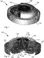
Fig. 1 is a perspective, partly cutaway, view of a camera assembly having the inventive cooling arrangement according to one embodiment thereof. -
Fig. 2 is a sectional view, with a 90-degree section removed, illustrating an example of an airflow through a cooling arrangement according to one embodiment thereof. -
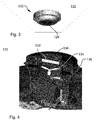
Fig. 3 is a perspective view of a camera assembly arranged in a ceiling. -
Fig. 4 is a detailed sectional view illustrating further details of the cooling arrangement - A
camera assembly 100, in which the present invention may be embodied, is illustrated in the perspective view ofFig. 1 . Thecamera assembly 100 comprises ahousing 102, one ormore camera heads 104, and atransparent dome 106. A similar version of such a camera assembly is disclosed inEP2887328 , by the present applicant. - Part of the
transparent dome 106 has been cutaway so somecamera heads 104 are clearly visible. Acentral part 108 of the assembly may comprise connectors, control units etc. (not shown), for receiving, processing and forwarding the result of the imaging effected by thecamera heads 104. Thecentral part 108 will in this embodiment comprise the cooling arrangement, or at least a portion thereof, and we will return to that. First, two things may be noted to increase the understanding of the present illustratedcamera assembly 100; each of the individually mentioned portions may in fact comprise several parts, e.g. the "housing 102" may comprise a base, a chassis, a bracket, several covers etc. Furthermore, these parts may be manufactured from different materials (or the same material). Since these individual parts are not considered essential for understanding or enabling the present invention we will refrain from providing a detailed description of them, yet further information is readily found by observing commercially available products, e.g. from the present applicant. The other thing is that in the illustrated view thecamera assembly 100 is basically upside-down as compared to a normal installation where the camera assembly is attached to a ceiling or mounting base with the camera heads 104 facing down and to the sides to surveil a designated area. - Returning now to the
central part 108, it will contain a portion of the cooling arrangement, an embodiment of which is most readily explained referring toFig. 2 . The most prominent part is theheat dissipation portion 110 extending essentially from a top to a bottom of thecamera assembly 100. The heat dissipation portion provides a physical barrier between a compartment configured to house the camera head(s) and achannel 112 extending through the heat dissipation portion. Furthermore, the heat dissipation portion has a flange or surface for receiving a seal configured to seal off the contact area between thedome 104 and the heat dissipation portion. Further constructional details may be involved in theseal arrangement 114. - For the purposes of the present invention it is of the essence that the heat dissipation portion is made from a material with good properties in regard of heat conduction, such that it transports heat efficiently. It may also be noted that the heat dissipation portion is a structural part of the camera assembly, adding to its functionality.
- If the heat dissipation portion should be coated, using electro deposition is preferred over e.g., powder coating in order to maintain the thermal conductivity. However, powder coating or other surface treatments may be conceivable depending on the application. The properties of transporting heat efficiently could also be provided in a more elaborate manner, which also would be acceptable from a functional viewpoint, though such a more elaborate solution would be likely to incorporate a higher cost. Such more elaborate solutions could correspond to using heat pipes. A more low-tech solution is to use a material having a higher thermal conductivity, such as copper, which would have an effect on cost of the device.
- In general, parts may be manufactured from different materials (or the same material) depending on the desired properties. Parts that should have increased rigidity or heat conducting properties (such as may be the case for portions of the housing, in particular the chassis thereof, as well as the bracket) could be made of, e.g., aluminum. Suitable processes for applying a color to such parts may be powder coating or electro deposition, as already mentioned. Other parts may be made from colored plastics, and the transparent dome may be made from, e.g., acrylic or polycarbonate.
- The physical barrier provided allows for outside air to access the channel without any direct impact on the camera head compartment. The
heat dissipation portion 110 is attached to the housing at thechassis 116, and thechannel 112 extends into a manifold 118 between thechassis 116 and thebracket 120 of thehousing 102. In the illustrated embodiment the manifold 118 extends to peripheral edges of the housing, and exits through anoutlet arrangement 122 provided in the housing. As such, the outlet arrangement will result in a flow of air over some surfaces of the dome, which may reduce contamination from the surrounding air, in particular if the air used for cooling is filtered. - In the illustrated embodiment the outlet is embodied as a
vent arrangement 122, yet the shape, size and position of the outlet may vary with application. As an example, the outlets, suggestively in the form of a vent grid, could be arranged closer to the base of the housing, i.e. more remote from the inlet (to be described later), in order to increase convection. Also, the shape of the manifold 118 may vary, yet one design feature may be that it should pass as close as possible to heat-generating components of the camera assembly. Concentrating the cooling air flow such that it passes an area where the most heat is generated would be considered suitable. To the same point, heat-generating components may be arranged in direct physical contact with theheat dissipation portion 110, which is the case for the processor indicated at 124. - The cooling arrangement also comprises an
inlet 126, and for the present embodiment the inlet is arranged in the center of the camera assembly, but more importantly it guides an airflow directly into theheat dissipation portion 110 and thechannel 112 where it may serve its purpose of transporting heat away from the heat dissipation portion. The interior of the heat dissipation portion may also comprise coolingflanges 128, serving the purpose of increasing the contact area between the channel walls and the flow of air, in a per se known manner. - Now, let us have a look at a use situation, where the
camera assembly 100 is arranged in aceiling 130, as shown inFig. 3 . As compared to the camera assembly as shown inFigs. 1 and 2 it is now turned upside down, which is the expected use position. The bracket has been attached to the ceiling, and the chassis and the rest of the housing have been attached to the bracket. It is readily appreciated that the inlet will be a lower (not necessarily, but possibly, the lowest) point of the camera assembly in this use situation. As the camera heads and processors heat up, so will the heat dissipation portion. Next, the air inside the channel of the heat dissipation portion will heat up, and as a result it will start to transport upwards, as a result of convection. The stream of heated air will continue to the outlet of the camera assembly, and a continuous flow of air from the surroundings will enter through the inlet as a result. Heat will consequently be transferred from the heat-generating components, to the heat dissipation portion, to the air, and then be expelled from the camera assembly, which all in all results in an adequate cooling of the assembly. The flow described is illustrated inFig. 2 , yet the direction of the flow makes more sense knowing that the assembly is turned upside down inFig. 2 . - The
channel 112 has no fluid communication with the camera compartment, and for that reason the qualities of the outside air is not critical for the functionality of the camera assembly. However, in an application where there, e.g., is a higher dust content in the surrounding air, afilter 132 may be arranged in the airflow through the channel. In one or more embodiments a filter may be arranged by removing acap 136 of the inlet (with a screwdriver or by turning the cap manually), arranging a filter that fits in a filter holder, and putting the cap back on again. The filter should obviously have a shape that conforms to the portion of the channel in which it is arranged, which in the present case results in that thefilter 132 will have a cylindrical shape, a sectional view of which is shown inFig. 4 . - In another embodiment, which may or may not be combined with the embodiment comprising the filter, a
fan 134 may be arranged in the channel. The purpose of the fan is to increase the airflow and in that way to increase the heat transfer further. The fan is merely illustrated as a propeller inFig. 4 , and in a real embodiment the fan could be provided in the form of a duct fan that is insertable in the channel and which is powered from the power unit of the camera. The choice of fan may vary with several factors, such as the amount of power available and a desired cooling efficiency. Notably, apart from cooling, the fan could assist in maintaining the dome free from dust and debris, as mentioned in relation to the discussion about theoutlets 122, or even be used to de-ice or dry the exterior of the dome by blowing the (now preheated) exhaust air over the exterior surface of the dome. In other installations the air used for cooling may be contaminated to the extent that it is preferable to direct the exhaust away from the dome, to decrease the deposition of grease and dirt, etc. - In order to access the fan, e.g., for service or inspection purposes, the upper (in
Fig. 4 )part 138 of the heat dissipation portion may be removable. This removable part may be held in place by means of screws or clamps, yet it may also be held in place by a pressure exerted by thedome 104. In an assembled state an inner diameter of the dome will abut an outer flange of the heat dissipation portion (with a seal arranged therebetween), which makes it possible for the dome to hold the removable part in place. - The camera assembly is shown as having a circular cross section, and this is presently a preferred embodiment. However, the cooling arrangement could obviously be used in camera assemblies having a different shape as well. Also, the cooling arrangement is placed in a center of the camera assembly, a location which is advantageous in the present embodiment, but which may not be as relevant for other embodiments.
- It will be appreciated that a person skilled in the art can modify the above-described embodiments in many ways and still use the advantages of the invention as shown in the embodiments above. As an example, the outlet or exhaust of the channel may be arranged on the lateral sides of the camera assembly, or even be directed back so as to exit in the center of the housing. If there is no ceiling above the bracket on which the camera assembly is arranged the outlet could even be placed on an upper side of the camera assembly, on the side opposite to where the inlet is positioned. Thus, the invention should not be limited to the shown embodiments but should only be defined by the appended claims. Additionally, as the skilled person understands, the shown embodiments may be combined.
Claims (12)
- A camera assembly (100) having a housing (102), a transparent dome (106), and configured to receive at least one camera head (104) arranged in the housing (102), inside the transparent dome (104), wherein- the housing (102) comprises a cooling arrangement having a heat dissipation portion (110) arranged within the housing (102), said heat dissipating portion (110) forming a channel (112) for cooling airflow, which channel (112) extends through an inlet (126) in the transparent dome (106), wherein- said heat dissipation portion (110) is made from a material configured to transfer heat efficiently, and wherein- the heat dissipation portion (110) constitutes a physical barrier between the channel (112) and a compartment where said at least one camera head (104) is arranged.
- The camera assembly of claim 1, wherein the heat dissipation portion (110) extends to a chassis (116) of the housing (102).
- The camera assembly of claim 2, wherein the channel (112) extends to or through the chassis (116) and continues as a manifold (118) extending outwards towards a perimeter of the housing (102).
- The camera assembly of claim 2 or 3, wherein also the chassis (116) is made from a material configured to transfer heat efficiently
- The camera assembly of any one of claims 1-4, wherein the heat dissipation portion (110) comprises a fitting for a processing unit of the camera assembly (100).
- The camera assembly of any one of claims 1-5, wherein a fan (134) is arranged in the heat dissipation portion (110) in order to enhance the airflow.
- The camera assembly of any one of claims 1-6, wherein the inlet (126) of the channel (112) is arranged at a center of the camera assembly (100), and wherein an outlet (122) of the channel (112) is arranged at a perimeter of the camera assembly (100).
- The camera assembly of any one of claims 1-7, wherein an exchangeable filter unit (132) is arranged near the inlet (126) of the channel (112).
- The camera assembly of any one of claims 1-8, wherein an upper part of the heat dissipation portion (110), at an end of the heat dissipation portion (110) extending through the dome (106), is removable for access to the interior of the heat dissipation portion (110).
- The camera assembly of claims 8 and 9, wherein the removable upper part of the heat dissipation portion (110) comprises a cap (136) below which the exchangeable filter (132) may be arranged.
- The camera assembly of claim 9 or 10, wherein the removable upper part is held in place towards the rest of the heat dissipation portion (110) by means of a pressure exerted by the dome (106).
- The camera assembly of any one of claims 1-11, further comprising at least one camera head (104), such as 1, 2, 3, 4, 5 or more camera heads (104).
Priority Applications (6)
| Application Number | Priority Date | Filing Date | Title |
|---|---|---|---|
| EP18166589.4A EP3553769B1 (en) | 2018-04-10 | 2018-04-10 | A camera assembly having a cooling arrangement |
| KR1020190019434A KR102178788B1 (en) | 2018-04-10 | 2019-02-19 | A camera assembly having a cooling arrangement |
| US16/354,726 US10887493B2 (en) | 2018-04-10 | 2019-03-15 | Camera assembly having a cooling arrangement |
| CN201910216197.5A CN110361911B (en) | 2018-04-10 | 2019-03-21 | Camera assembly with cooling device |
| TW108110223A TWI732196B (en) | 2018-04-10 | 2019-03-25 | A camera assembly having a cooling arrangement |
| JP2019066458A JP6966503B2 (en) | 2018-04-10 | 2019-03-29 | Camera assembly with cooling configuration |
Applications Claiming Priority (1)
| Application Number | Priority Date | Filing Date | Title |
|---|---|---|---|
| EP18166589.4A EP3553769B1 (en) | 2018-04-10 | 2018-04-10 | A camera assembly having a cooling arrangement |
Publications (2)
| Publication Number | Publication Date |
|---|---|
| EP3553769A1 EP3553769A1 (en) | 2019-10-16 |
| EP3553769B1 true EP3553769B1 (en) | 2020-06-03 |
Family
ID=61971920
Family Applications (1)
| Application Number | Title | Priority Date | Filing Date |
|---|---|---|---|
| EP18166589.4A Active EP3553769B1 (en) | 2018-04-10 | 2018-04-10 | A camera assembly having a cooling arrangement |
Country Status (6)
| Country | Link |
|---|---|
| US (1) | US10887493B2 (en) |
| EP (1) | EP3553769B1 (en) |
| JP (1) | JP6966503B2 (en) |
| KR (1) | KR102178788B1 (en) |
| CN (1) | CN110361911B (en) |
| TW (1) | TWI732196B (en) |
Families Citing this family (2)
| Publication number | Priority date | Publication date | Assignee | Title |
|---|---|---|---|---|
| EP3934226B1 (en) * | 2020-07-03 | 2022-06-22 | Axis AB | A camera and a method |
| KR102835941B1 (en) * | 2023-07-11 | 2025-07-18 | 주식회사 아이디스 | Bottom housing of dome camera with efficient heat dissipation |
Family Cites Families (35)
| Publication number | Priority date | Publication date | Assignee | Title |
|---|---|---|---|---|
| US4320949A (en) | 1976-03-03 | 1982-03-23 | Pagano Raymond V | Weatherized housing assembly for camera |
| US5394184A (en) * | 1993-08-30 | 1995-02-28 | Sensormatic Electronics Corporation | Surveillance assembly having circumferential delivery of forced air to viewing bubble |
| JP3342273B2 (en) * | 1995-12-19 | 2002-11-05 | スター精密株式会社 | Surveillance camera device |
| US6061087A (en) | 1998-07-16 | 2000-05-09 | Sensormatic Electronics Corporation | Outdoor enclosure for video surveillance system |
| US6643456B1 (en) | 1999-07-09 | 2003-11-04 | Robert Bosch, Gmbh | Environmental shroud |
| US6850025B1 (en) | 2000-06-30 | 2005-02-01 | Sensormatic Electronics Corporation | Integrated enclosure and controller for video surveillance camera |
| US20040169771A1 (en) * | 2003-01-02 | 2004-09-02 | Washington Richard G | Thermally cooled imaging apparatus |
| US20050213960A1 (en) * | 2003-10-31 | 2005-09-29 | Cyrus Baldwin | Heat pumped surveillance camera housing and method of manufacturing the same |
| KR100545903B1 (en) * | 2003-11-12 | 2006-01-31 | 김배훈 | 360 ° panoramic camera device and its operation method |
| WO2006012524A2 (en) * | 2004-07-23 | 2006-02-02 | Vicon Industries Inc. | Surveillance camera system |
| GB0910431D0 (en) | 2009-06-17 | 2009-07-29 | Murphy David B | A piece of street furniture which is a multifunctional communication, surveillance apparatus |
| CN102098426B (en) * | 2009-12-09 | 2014-07-30 | 天津天地伟业数码科技有限公司 | Temperature control structure for infrared high-speed spherical camera |
| US20120154521A1 (en) | 2010-10-26 | 2012-06-21 | Townsend Julie A | 360-degree camera head for unmanned surface sea vehicle |
| JP5717494B2 (en) * | 2011-03-24 | 2015-05-13 | 株式会社トプコン | All-around camera |
| JP2013148634A (en) * | 2012-01-17 | 2013-08-01 | Tamron Co Ltd | Camera |
| WO2014039624A1 (en) * | 2012-09-06 | 2014-03-13 | Sensormatic Electronics, LLC | Pan, tilt, zoom camera system for cooling electronics |
| JP5983398B2 (en) * | 2012-12-28 | 2016-08-31 | 株式会社Jvcケンウッド | Imaging device |
| WO2015063890A1 (en) * | 2013-10-30 | 2015-05-07 | 株式会社アシストユウ | Portable remote monitor camera |
| EP2887328B1 (en) | 2013-12-19 | 2016-04-20 | Axis AB | Monitoring devices slidably mounted on a rail releasably locked to predetermined positions |
| EP3187934B1 (en) * | 2014-08-29 | 2018-11-07 | SZ DJI Technology Co., Ltd. | Image capturing module |
| US10440332B2 (en) * | 2014-11-07 | 2019-10-08 | SeeScan, Inc. | Inspection camera devices and methods with selectively illuminated multisensor imaging |
| JP6727889B2 (en) * | 2015-04-10 | 2020-07-22 | ブラックマジック デザイン ピーティーワイ リミテッドBlackmagic Design Pty Ltd | Digital video camera |
| CN205071148U (en) * | 2015-10-28 | 2016-03-02 | 杭州海康威视数字技术股份有限公司 | Panorama concatenation camera |
| US10488737B2 (en) * | 2016-01-14 | 2019-11-26 | Avigilon Corporation | Dome camera |
| US9939859B2 (en) * | 2016-03-17 | 2018-04-10 | Google Llc | Electronic device with a cooling structure |
| JP6652305B2 (en) * | 2016-04-28 | 2020-02-19 | キヤノン株式会社 | Imaging device and image monitoring system |
| US10212318B2 (en) * | 2016-05-11 | 2019-02-19 | Canon Kabushiki Kaisha | Image pickup apparatus such as network camera, and image monitoring system |
| JP2016224450A (en) * | 2016-07-29 | 2016-12-28 | 株式会社Jvcケンウッド | Rotation device |
| KR102596489B1 (en) * | 2016-10-10 | 2023-11-01 | 한화비전 주식회사 | Cooling apparatus for surveillance camera |
| CN206450949U (en) * | 2016-12-06 | 2017-08-29 | 杭州海康威视数字技术股份有限公司 | A kind of video camera cooling structure and the video camera with it |
| US10812754B2 (en) * | 2017-01-27 | 2020-10-20 | Ivan Onuchin | Cooling system for a 360 degree camera |
| CN206542527U (en) * | 2017-03-09 | 2017-10-03 | 中磊电子(苏州)有限公司 | Network monitor |
| JP6846976B2 (en) * | 2017-04-12 | 2021-03-24 | パナソニックi−PROセンシングソリューションズ株式会社 | Camera device and gravity compensation method |
| JP2019020557A (en) * | 2017-07-14 | 2019-02-07 | キヤノン株式会社 | Imaging apparatus |
| EP3447574B1 (en) * | 2017-08-21 | 2019-07-31 | Axis AB | Camera and method for controlled dew formation inside a camera |
-
2018
- 2018-04-10 EP EP18166589.4A patent/EP3553769B1/en active Active
-
2019
- 2019-02-19 KR KR1020190019434A patent/KR102178788B1/en active Active
- 2019-03-15 US US16/354,726 patent/US10887493B2/en active Active
- 2019-03-21 CN CN201910216197.5A patent/CN110361911B/en active Active
- 2019-03-25 TW TW108110223A patent/TWI732196B/en active
- 2019-03-29 JP JP2019066458A patent/JP6966503B2/en active Active
Non-Patent Citations (1)
| Title |
|---|
| None * |
Also Published As
| Publication number | Publication date |
|---|---|
| JP2019215523A (en) | 2019-12-19 |
| JP6966503B2 (en) | 2021-11-17 |
| EP3553769A1 (en) | 2019-10-16 |
| CN110361911A (en) | 2019-10-22 |
| CN110361911B (en) | 2021-03-19 |
| US20190312994A1 (en) | 2019-10-10 |
| TW201944162A (en) | 2019-11-16 |
| KR20190118500A (en) | 2019-10-18 |
| KR102178788B1 (en) | 2020-11-13 |
| US10887493B2 (en) | 2021-01-05 |
| TWI732196B (en) | 2021-07-01 |
Similar Documents
| Publication | Publication Date | Title |
|---|---|---|
| US10578952B2 (en) | Image capturing module | |
| JP6727889B2 (en) | Digital video camera | |
| CN107113371B (en) | Image acquisition module and aerial photography aircraft | |
| US8792023B2 (en) | Heat dissipating system for an image pickup apparatus | |
| EP3553769B1 (en) | A camera assembly having a cooling arrangement | |
| US20110203770A1 (en) | Equipment case | |
| JP7615087B2 (en) | Imaging device | |
| JP6863662B2 (en) | Aerial camera and electronic equipment and unmanned aerial vehicle equipped with it | |
| CN204089975U (en) | Image capture module | |
| CN112702480A (en) | Camera and communication equipment | |
| JP7111910B2 (en) | Imaging device | |
| JPH09172564A (en) | Surveillance camera device | |
| JP4954625B2 (en) | Surveillance camera | |
| CN117440876A (en) | Robot torso with thermal management | |
| CN102075673A (en) | Imaging apparatus | |
| CN114096466A (en) | Unmanned aerial vehicle | |
| JP2023168933A (en) | Imaging apparatus and imaging element unit | |
| JPH0635577Y2 (en) | TV camera device for outdoor shooting | |
| EP2180775A1 (en) | Equipment case | |
| JP2023036244A (en) | Imaging device | |
| JP2026060573A (en) | Camera device | |
| JP2025130332A (en) | Imaging device and cooling method thereof | |
| JP2011229118A (en) | Electronic apparatus using heat dissipation unit | |
| JP2018078458A (en) | Monitoring device |
Legal Events
| Date | Code | Title | Description |
|---|---|---|---|
| PUAI | Public reference made under article 153(3) epc to a published international application that has entered the european phase |
Free format text: ORIGINAL CODE: 0009012 |
|
| STAA | Information on the status of an ep patent application or granted ep patent |
Free format text: STATUS: REQUEST FOR EXAMINATION WAS MADE |
|
| 17P | Request for examination filed |
Effective date: 20181107 |
|
| AK | Designated contracting states |
Kind code of ref document: A1 Designated state(s): AL AT BE BG CH CY CZ DE DK EE ES FI FR GB GR HR HU IE IS IT LI LT LU LV MC MK MT NL NO PL PT RO RS SE SI SK SM TR |
|
| AX | Request for extension of the european patent |
Extension state: BA ME |
|
| STAA | Information on the status of an ep patent application or granted ep patent |
Free format text: STATUS: EXAMINATION IS IN PROGRESS |
|
| 17Q | First examination report despatched |
Effective date: 20191202 |
|
| GRAP | Despatch of communication of intention to grant a patent |
Free format text: ORIGINAL CODE: EPIDOSNIGR1 |
|
| STAA | Information on the status of an ep patent application or granted ep patent |
Free format text: STATUS: GRANT OF PATENT IS INTENDED |
|
| INTG | Intention to grant announced |
Effective date: 20200323 |
|
| GRAS | Grant fee paid |
Free format text: ORIGINAL CODE: EPIDOSNIGR3 |
|
| GRAA | (expected) grant |
Free format text: ORIGINAL CODE: 0009210 |
|
| STAA | Information on the status of an ep patent application or granted ep patent |
Free format text: STATUS: THE PATENT HAS BEEN GRANTED |
|
| AK | Designated contracting states |
Kind code of ref document: B1 Designated state(s): AL AT BE BG CH CY CZ DE DK EE ES FI FR GB GR HR HU IE IS IT LI LT LU LV MC MK MT NL NO PL PT RO RS SE SI SK SM TR |
|
| REG | Reference to a national code |
Ref country code: GB Ref legal event code: FG4D |
|
| REG | Reference to a national code |
Ref country code: CH Ref legal event code: EP Ref country code: AT Ref legal event code: REF Ref document number: 1277845 Country of ref document: AT Kind code of ref document: T Effective date: 20200615 |
|
| REG | Reference to a national code |
Ref country code: DE Ref legal event code: R096 Ref document number: 602018004980 Country of ref document: DE |
|
| REG | Reference to a national code |
Ref country code: SE Ref legal event code: TRGR |
|
| REG | Reference to a national code |
Ref country code: LT Ref legal event code: MG4D |
|
| PG25 | Lapsed in a contracting state [announced via postgrant information from national office to epo] |
Ref country code: FI Free format text: LAPSE BECAUSE OF FAILURE TO SUBMIT A TRANSLATION OF THE DESCRIPTION OR TO PAY THE FEE WITHIN THE PRESCRIBED TIME-LIMIT Effective date: 20200603 Ref country code: GR Free format text: LAPSE BECAUSE OF FAILURE TO SUBMIT A TRANSLATION OF THE DESCRIPTION OR TO PAY THE FEE WITHIN THE PRESCRIBED TIME-LIMIT Effective date: 20200904 Ref country code: NO Free format text: LAPSE BECAUSE OF FAILURE TO SUBMIT A TRANSLATION OF THE DESCRIPTION OR TO PAY THE FEE WITHIN THE PRESCRIBED TIME-LIMIT Effective date: 20200903 Ref country code: LT Free format text: LAPSE BECAUSE OF FAILURE TO SUBMIT A TRANSLATION OF THE DESCRIPTION OR TO PAY THE FEE WITHIN THE PRESCRIBED TIME-LIMIT Effective date: 20200603 |
|
| REG | Reference to a national code |
Ref country code: NL Ref legal event code: MP Effective date: 20200603 |
|
| PG25 | Lapsed in a contracting state [announced via postgrant information from national office to epo] |
Ref country code: BG Free format text: LAPSE BECAUSE OF FAILURE TO SUBMIT A TRANSLATION OF THE DESCRIPTION OR TO PAY THE FEE WITHIN THE PRESCRIBED TIME-LIMIT Effective date: 20200903 Ref country code: RS Free format text: LAPSE BECAUSE OF FAILURE TO SUBMIT A TRANSLATION OF THE DESCRIPTION OR TO PAY THE FEE WITHIN THE PRESCRIBED TIME-LIMIT Effective date: 20200603 Ref country code: HR Free format text: LAPSE BECAUSE OF FAILURE TO SUBMIT A TRANSLATION OF THE DESCRIPTION OR TO PAY THE FEE WITHIN THE PRESCRIBED TIME-LIMIT Effective date: 20200603 Ref country code: LV Free format text: LAPSE BECAUSE OF FAILURE TO SUBMIT A TRANSLATION OF THE DESCRIPTION OR TO PAY THE FEE WITHIN THE PRESCRIBED TIME-LIMIT Effective date: 20200603 |
|
| REG | Reference to a national code |
Ref country code: AT Ref legal event code: MK05 Ref document number: 1277845 Country of ref document: AT Kind code of ref document: T Effective date: 20200603 |
|
| PG25 | Lapsed in a contracting state [announced via postgrant information from national office to epo] |
Ref country code: NL Free format text: LAPSE BECAUSE OF FAILURE TO SUBMIT A TRANSLATION OF THE DESCRIPTION OR TO PAY THE FEE WITHIN THE PRESCRIBED TIME-LIMIT Effective date: 20200603 Ref country code: AL Free format text: LAPSE BECAUSE OF FAILURE TO SUBMIT A TRANSLATION OF THE DESCRIPTION OR TO PAY THE FEE WITHIN THE PRESCRIBED TIME-LIMIT Effective date: 20200603 |
|
| PG25 | Lapsed in a contracting state [announced via postgrant information from national office to epo] |
Ref country code: ES Free format text: LAPSE BECAUSE OF FAILURE TO SUBMIT A TRANSLATION OF THE DESCRIPTION OR TO PAY THE FEE WITHIN THE PRESCRIBED TIME-LIMIT Effective date: 20200603 Ref country code: AT Free format text: LAPSE BECAUSE OF FAILURE TO SUBMIT A TRANSLATION OF THE DESCRIPTION OR TO PAY THE FEE WITHIN THE PRESCRIBED TIME-LIMIT Effective date: 20200603 Ref country code: PT Free format text: LAPSE BECAUSE OF FAILURE TO SUBMIT A TRANSLATION OF THE DESCRIPTION OR TO PAY THE FEE WITHIN THE PRESCRIBED TIME-LIMIT Effective date: 20201006 Ref country code: IT Free format text: LAPSE BECAUSE OF FAILURE TO SUBMIT A TRANSLATION OF THE DESCRIPTION OR TO PAY THE FEE WITHIN THE PRESCRIBED TIME-LIMIT Effective date: 20200603 Ref country code: SM Free format text: LAPSE BECAUSE OF FAILURE TO SUBMIT A TRANSLATION OF THE DESCRIPTION OR TO PAY THE FEE WITHIN THE PRESCRIBED TIME-LIMIT Effective date: 20200603 Ref country code: EE Free format text: LAPSE BECAUSE OF FAILURE TO SUBMIT A TRANSLATION OF THE DESCRIPTION OR TO PAY THE FEE WITHIN THE PRESCRIBED TIME-LIMIT Effective date: 20200603 Ref country code: CZ Free format text: LAPSE BECAUSE OF FAILURE TO SUBMIT A TRANSLATION OF THE DESCRIPTION OR TO PAY THE FEE WITHIN THE PRESCRIBED TIME-LIMIT Effective date: 20200603 Ref country code: RO Free format text: LAPSE BECAUSE OF FAILURE TO SUBMIT A TRANSLATION OF THE DESCRIPTION OR TO PAY THE FEE WITHIN THE PRESCRIBED TIME-LIMIT Effective date: 20200603 |
|
| PG25 | Lapsed in a contracting state [announced via postgrant information from national office to epo] |
Ref country code: SK Free format text: LAPSE BECAUSE OF FAILURE TO SUBMIT A TRANSLATION OF THE DESCRIPTION OR TO PAY THE FEE WITHIN THE PRESCRIBED TIME-LIMIT Effective date: 20200603 Ref country code: PL Free format text: LAPSE BECAUSE OF FAILURE TO SUBMIT A TRANSLATION OF THE DESCRIPTION OR TO PAY THE FEE WITHIN THE PRESCRIBED TIME-LIMIT Effective date: 20200603 Ref country code: IS Free format text: LAPSE BECAUSE OF FAILURE TO SUBMIT A TRANSLATION OF THE DESCRIPTION OR TO PAY THE FEE WITHIN THE PRESCRIBED TIME-LIMIT Effective date: 20201003 |
|
| RAP2 | Party data changed (patent owner data changed or rights of a patent transferred) |
Owner name: AXIS AB |
|
| REG | Reference to a national code |
Ref country code: DE Ref legal event code: R097 Ref document number: 602018004980 Country of ref document: DE |
|
| PLBE | No opposition filed within time limit |
Free format text: ORIGINAL CODE: 0009261 |
|
| STAA | Information on the status of an ep patent application or granted ep patent |
Free format text: STATUS: NO OPPOSITION FILED WITHIN TIME LIMIT |
|
| PG25 | Lapsed in a contracting state [announced via postgrant information from national office to epo] |
Ref country code: DK Free format text: LAPSE BECAUSE OF FAILURE TO SUBMIT A TRANSLATION OF THE DESCRIPTION OR TO PAY THE FEE WITHIN THE PRESCRIBED TIME-LIMIT Effective date: 20200603 |
|
| 26N | No opposition filed |
Effective date: 20210304 |
|
| PG25 | Lapsed in a contracting state [announced via postgrant information from national office to epo] |
Ref country code: MC Free format text: LAPSE BECAUSE OF FAILURE TO SUBMIT A TRANSLATION OF THE DESCRIPTION OR TO PAY THE FEE WITHIN THE PRESCRIBED TIME-LIMIT Effective date: 20200603 |
|
| PG25 | Lapsed in a contracting state [announced via postgrant information from national office to epo] |
Ref country code: LU Free format text: LAPSE BECAUSE OF NON-PAYMENT OF DUE FEES Effective date: 20210410 |
|
| REG | Reference to a national code |
Ref country code: BE Ref legal event code: MM Effective date: 20210430 |
|
| PG25 | Lapsed in a contracting state [announced via postgrant information from national office to epo] |
Ref country code: CH Free format text: LAPSE BECAUSE OF NON-PAYMENT OF DUE FEES Effective date: 20210430 Ref country code: LI Free format text: LAPSE BECAUSE OF NON-PAYMENT OF DUE FEES Effective date: 20210430 |
|
| PG25 | Lapsed in a contracting state [announced via postgrant information from national office to epo] |
Ref country code: IE Free format text: LAPSE BECAUSE OF NON-PAYMENT OF DUE FEES Effective date: 20210410 |
|
| PG25 | Lapsed in a contracting state [announced via postgrant information from national office to epo] |
Ref country code: IS Free format text: LAPSE BECAUSE OF FAILURE TO SUBMIT A TRANSLATION OF THE DESCRIPTION OR TO PAY THE FEE WITHIN THE PRESCRIBED TIME-LIMIT Effective date: 20201003 |
|
| PG25 | Lapsed in a contracting state [announced via postgrant information from national office to epo] |
Ref country code: BE Free format text: LAPSE BECAUSE OF NON-PAYMENT OF DUE FEES Effective date: 20210430 |
|
| P01 | Opt-out of the competence of the unified patent court (upc) registered |
Effective date: 20230505 |
|
| PG25 | Lapsed in a contracting state [announced via postgrant information from national office to epo] |
Ref country code: CY Free format text: LAPSE BECAUSE OF FAILURE TO SUBMIT A TRANSLATION OF THE DESCRIPTION OR TO PAY THE FEE WITHIN THE PRESCRIBED TIME-LIMIT Effective date: 20200603 |
|
| PG25 | Lapsed in a contracting state [announced via postgrant information from national office to epo] |
Ref country code: HU Free format text: LAPSE BECAUSE OF FAILURE TO SUBMIT A TRANSLATION OF THE DESCRIPTION OR TO PAY THE FEE WITHIN THE PRESCRIBED TIME-LIMIT; INVALID AB INITIO Effective date: 20180410 |
|
| PG25 | Lapsed in a contracting state [announced via postgrant information from national office to epo] |
Ref country code: SI Free format text: LAPSE BECAUSE OF FAILURE TO SUBMIT A TRANSLATION OF THE DESCRIPTION OR TO PAY THE FEE WITHIN THE PRESCRIBED TIME-LIMIT Effective date: 20200603 |
|
| PG25 | Lapsed in a contracting state [announced via postgrant information from national office to epo] |
Ref country code: MK Free format text: LAPSE BECAUSE OF FAILURE TO SUBMIT A TRANSLATION OF THE DESCRIPTION OR TO PAY THE FEE WITHIN THE PRESCRIBED TIME-LIMIT Effective date: 20200603 |
|
| PG25 | Lapsed in a contracting state [announced via postgrant information from national office to epo] |
Ref country code: MT Free format text: LAPSE BECAUSE OF FAILURE TO SUBMIT A TRANSLATION OF THE DESCRIPTION OR TO PAY THE FEE WITHIN THE PRESCRIBED TIME-LIMIT Effective date: 20200603 |
|
| PGFP | Annual fee paid to national office [announced via postgrant information from national office to epo] |
Ref country code: DE Payment date: 20250319 Year of fee payment: 8 |
|
| PG25 | Lapsed in a contracting state [announced via postgrant information from national office to epo] |
Ref country code: TR Free format text: LAPSE BECAUSE OF FAILURE TO SUBMIT A TRANSLATION OF THE DESCRIPTION OR TO PAY THE FEE WITHIN THE PRESCRIBED TIME-LIMIT Effective date: 20200603 |
|
| PGFP | Annual fee paid to national office [announced via postgrant information from national office to epo] |
Ref country code: SE Payment date: 20260319 Year of fee payment: 9 |
|
| PGFP | Annual fee paid to national office [announced via postgrant information from national office to epo] |
Ref country code: GB Payment date: 20260319 Year of fee payment: 9 |
|
| PGFP | Annual fee paid to national office [announced via postgrant information from national office to epo] |
Ref country code: FR Payment date: 20260320 Year of fee payment: 9 |