EP3933912A1 - Kühlkörper für ein elektronisches leistungsbauteil - Google Patents
Kühlkörper für ein elektronisches leistungsbauteil Download PDFInfo
- Publication number
- EP3933912A1 EP3933912A1 EP20183240.9A EP20183240A EP3933912A1 EP 3933912 A1 EP3933912 A1 EP 3933912A1 EP 20183240 A EP20183240 A EP 20183240A EP 3933912 A1 EP3933912 A1 EP 3933912A1
- Authority
- EP
- European Patent Office
- Prior art keywords
- heat
- heat sink
- recess
- electronic component
- circuit board
- Prior art date
- Legal status (The legal status is an assumption and is not a legal conclusion. Google has not performed a legal analysis and makes no representation as to the accuracy of the status listed.)
- Pending
Links
Images





Classifications
-
- H—ELECTRICITY
- H05—ELECTRIC TECHNIQUES NOT OTHERWISE PROVIDED FOR
- H05K—PRINTED CIRCUITS; CASINGS OR CONSTRUCTIONAL DETAILS OF ELECTRIC APPARATUS; MANUFACTURE OF ASSEMBLAGES OF ELECTRICAL COMPONENTS
- H05K1/00—Printed circuits
- H05K1/02—Details
- H05K1/0201—Thermal arrangements, e.g. for cooling, heating or preventing overheating
- H05K1/0203—Cooling of mounted components
- H05K1/0209—External configuration of printed circuit board adapted for heat dissipation, e.g. lay-out of conductors, coatings
-
- H—ELECTRICITY
- H05—ELECTRIC TECHNIQUES NOT OTHERWISE PROVIDED FOR
- H05K—PRINTED CIRCUITS; CASINGS OR CONSTRUCTIONAL DETAILS OF ELECTRIC APPARATUS; MANUFACTURE OF ASSEMBLAGES OF ELECTRICAL COMPONENTS
- H05K7/00—Constructional details common to different types of electric apparatus
- H05K7/20—Modifications to facilitate cooling, ventilating, or heating
- H05K7/2039—Modifications to facilitate cooling, ventilating, or heating characterised by the heat transfer by conduction from the heat generating element to a dissipating body
- H05K7/205—Heat-dissipating body thermally connected to heat generating element via thermal paths through printed circuit board [PCB]
-
- H—ELECTRICITY
- H05—ELECTRIC TECHNIQUES NOT OTHERWISE PROVIDED FOR
- H05K—PRINTED CIRCUITS; CASINGS OR CONSTRUCTIONAL DETAILS OF ELECTRIC APPARATUS; MANUFACTURE OF ASSEMBLAGES OF ELECTRICAL COMPONENTS
- H05K1/00—Printed circuits
- H05K1/02—Details
- H05K1/0201—Thermal arrangements, e.g. for cooling, heating or preventing overheating
- H05K1/0203—Cooling of mounted components
- H05K1/021—Components thermally connected to metal substrates or heat-sinks by insert mounting
-
- H—ELECTRICITY
- H05—ELECTRIC TECHNIQUES NOT OTHERWISE PROVIDED FOR
- H05K—PRINTED CIRCUITS; CASINGS OR CONSTRUCTIONAL DETAILS OF ELECTRIC APPARATUS; MANUFACTURE OF ASSEMBLAGES OF ELECTRICAL COMPONENTS
- H05K7/00—Constructional details common to different types of electric apparatus
- H05K7/20—Modifications to facilitate cooling, ventilating, or heating
- H05K7/2089—Modifications to facilitate cooling, ventilating, or heating for power electronics, e.g. for inverters for controlling motor
- H05K7/209—Heat transfer by conduction from internal heat source to heat radiating structure
-
- H—ELECTRICITY
- H10—SEMICONDUCTOR DEVICES; ELECTRIC SOLID-STATE DEVICES NOT OTHERWISE PROVIDED FOR
- H10W—GENERIC PACKAGES, INTERCONNECTIONS, CONNECTORS OR OTHER CONSTRUCTIONAL DETAILS OF DEVICES COVERED BY CLASS H10
- H10W40/00—Arrangements for thermal protection or thermal control
- H10W40/20—Arrangements for cooling
- H10W40/22—Arrangements for cooling characterised by their shape, e.g. having conical or cylindrical projections
- H10W40/226—Arrangements for cooling characterised by their shape, e.g. having conical or cylindrical projections characterised by projecting parts, e.g. fins to increase surface area
-
- H—ELECTRICITY
- H05—ELECTRIC TECHNIQUES NOT OTHERWISE PROVIDED FOR
- H05K—PRINTED CIRCUITS; CASINGS OR CONSTRUCTIONAL DETAILS OF ELECTRIC APPARATUS; MANUFACTURE OF ASSEMBLAGES OF ELECTRICAL COMPONENTS
- H05K2201/00—Indexing scheme relating to printed circuits covered by H05K1/00
- H05K2201/06—Thermal details
- H05K2201/066—Heatsink mounted on the surface of the printed circuit board [PCB]
-
- H—ELECTRICITY
- H05—ELECTRIC TECHNIQUES NOT OTHERWISE PROVIDED FOR
- H05K—PRINTED CIRCUITS; CASINGS OR CONSTRUCTIONAL DETAILS OF ELECTRIC APPARATUS; MANUFACTURE OF ASSEMBLAGES OF ELECTRICAL COMPONENTS
- H05K2201/00—Indexing scheme relating to printed circuits covered by H05K1/00
- H05K2201/10—Details of components or other objects attached to or integrated in a printed circuit board
- H05K2201/10007—Types of components
- H05K2201/10166—Transistor
-
- H—ELECTRICITY
- H05—ELECTRIC TECHNIQUES NOT OTHERWISE PROVIDED FOR
- H05K—PRINTED CIRCUITS; CASINGS OR CONSTRUCTIONAL DETAILS OF ELECTRIC APPARATUS; MANUFACTURE OF ASSEMBLAGES OF ELECTRICAL COMPONENTS
- H05K7/00—Constructional details common to different types of electric apparatus
- H05K7/20—Modifications to facilitate cooling, ventilating, or heating
- H05K7/2039—Modifications to facilitate cooling, ventilating, or heating characterised by the heat transfer by conduction from the heat generating element to a dissipating body
- H05K7/20509—Multiple-component heat spreaders; Multi-component heat-conducting support plates; Multi-component non-closed heat-conducting structures
-
- H—ELECTRICITY
- H10—SEMICONDUCTOR DEVICES; ELECTRIC SOLID-STATE DEVICES NOT OTHERWISE PROVIDED FOR
- H10W—GENERIC PACKAGES, INTERCONNECTIONS, CONNECTORS OR OTHER CONSTRUCTIONAL DETAILS OF DEVICES COVERED BY CLASS H10
- H10W40/00—Arrangements for thermal protection or thermal control
- H10W40/20—Arrangements for cooling
- H10W40/22—Arrangements for cooling characterised by their shape, e.g. having conical or cylindrical projections
Definitions
- the invention relates to a device with a heat sink for dissipating heat from an electronic component mounted on a circuit board, such as an electronic power component, for example a power transistor, a MOSFET, a shunt resistor or the like.
- a circuit board such as an electronic power component, for example a power transistor, a MOSFET, a shunt resistor or the like.
- the requirements placed on electronic components for controlling and / or switching electrical loads are very high.
- the advancing miniaturization in technology leads to structurally small components that have to control ever larger currents. This leads to a technically unavoidable waste heat in the electronic component, which has to be dissipated via appropriate heat sinks.
- the heat sinks are directly or indirectly in heat transferring connection with the electronic component itself and enlarge the heat-emitting area.
- At least one heat conduction path can also be provided in a circuit board for electronic assemblies in order to dissipate in particular the bottom heat and expediently also the top heat of the component.
- a heat transferring Connection can be created, e.g. B. by heat-transferring spacers. The arranged spacers interfere with an effective heat flow.
- the invention is based on the object of specifying a heat sink for dissipating heat from an electronic component mounted on a circuit board, with which, in particular, the bottom heat of the electronic component can be effectively dissipated.
- the heat sink stands with a foot section directly on a heat conducting section of the board that dissipates the bottom heat, so that the bottom heat is quickly dissipated via the heat conducting section of the board and the heat sink.
- the heat sink is also formed in the foot section with a recess in which the electronic component is at least partially accommodated. This ensures that the foot section stands directly on the heat-conducting section of the circuit board without the use of intermediate pieces, as a result of which good heat transfer is achieved.
- Two foot sections are advantageously formed on the base body of the heat sink. It is expediently provided that a foot section is formed on opposite sides of the recess.
- the circuit board has at least one heat-conducting section on opposite sides of the electronic component, the heat sink engaging over the electronic component and standing on the heat-conducting sections of the circuit board.
- the heat sink thus has a heat-transferring connection with the heat-conducting sections of the circuit board on both sides of the electronic component, which ensures good dissipation of the bottom heat.
- the heat sink stands directly on both heat conducting sections. The term “directly” expresses the fact that no further structural elements are arranged between the heat sink and the heat conducting sections.
- a heat-conducting material in the form of a pad or a heat-conducting paste or a heat-conducting adhesive can be provided for the heat sink and the heat-conducting sections of the circuit board.
- the heat sink spans the electronic component in the manner of a bridge.
- a common heat sink is assigned to the electronic components, such as power components, which are arranged in a row, together with the assigned heat-conducting sections of the board.
- the heat sink is expediently designed in such a way that the electronic components or power components of the row lie in a particularly common recess of the heat sink and the heat sink stands with at least one foot section on a heat conducting section next to the electronic components or power components on the board.
- the heat sink has, in particular, a foot section on both sides of the recess, which extends at least over the length of an electronic component or a series of electronic components or power components.
- the heat sink has, in particular, in the manner of a web on both sides of the recess running foot sections which extend over the length of the row of electronic components.
- Each foot section stands on both longitudinal sides of the row, preferably directly on a heat-conducting section of the board.
- At least one centering element fixed on the board engages in the recess of the cooling body, which centering element is suitable and intended to move the cooling body relative to the to align electronic component.
- at least one centering element is arranged in series with at least one electronic component.
- the centering element fixed on the circuit board engages in the recess and, through its position in the recess, aligns the heat sink relative to the electronic component.
- the recess is designed, in particular, to be larger than the component.
- the component lies in the recess with a lateral distance.
- the alignment of the heat sink relative to the electronic component ensures that the in particular electrically conductive heat sink does not come into contact with the often numerous connections of the electronic component, so that electrical short circuits are reliably avoided.
- the centering element ensures precise positioning of the heat sink on the heat-conducting section, so that good heat transfer is ensured and thus good heat dissipation is ensured.
- the rise in the operating temperature of the electronic component above a permissible temperature can be reliably prevented.
- the length of a centering element across the heat conducting section corresponds to the width of the recess in the heat sink such that a centering element engaging in the recess is suitable, align the heat sink transversely to the longitudinal direction of the heat conducting section and the electronic component.
- the centering element advantageously has a height that is less than or equal to the depth of the recess in the cooling body, in particular the height of the component above the surface of the circuit board. If, in a further development of the invention, the depth of the recess in the heat sink is also adapted to the overall height of the electronic component above the surface of the board, an electronic component or power component located in the recess can advantageously come into contact with the bottom of the recess, whereby the Top heat of the electronic component or the power component can be safely dissipated.
- the centering element can be designed as a rectangle in its basic shape, the length of the centering element being suitably adapted on the one hand to the width of the recess in the heat sink and advantageously bridging the distance between the heat conducting sections of a row.
- the centering element can consist of a thermally conductive material.
- the centering element advantageously consists of an electrically non-conductive material.
- the corners of the centering element are rounded. This ensures that slight angular misalignments of the centering element that occur during assembly do not lead to assembly problems when the heat sinks are placed on the row of electronic components or an individual power component.
- the end faces of the rectangular centering element are rounded.
- the rounded end faces preferably form segments of a circle, the end faces lying with a radius to a center point of a circle.
- At least one centering element is arranged in series with at least one electronic component.
- the length of the centering element transversely to the heat conducting section corresponds to the width of the recess in the base body of the heat sink so that a centering element engaging in the recess is suitable for aligning the heat sink transversely to the longitudinal direction of the row of electronic components or power components.
- a centering element expediently forms the beginning of a row and a centering element forms an end of a row of the electronic components or the power components.
- the electronic component lies in a heat-transferring connection in the recess, so that the top heat of the electronic component can also be dissipated.
- the design of the heat sink for simultaneous thermal contact of the heat conducting section of the circuit board and the electronic component leads to a compact design that is highly efficient for dissipating the operating heat of the electronic component.
- the electronic component has an underside facing the circuit board and an upper side facing away from the circuit board.
- the underside of the electronic component is in a heat-transferring connection with the heat-conducting section of the circuit board in order to dissipate bottom heat.
- the top of the electronic component can advantageously be in a heat-transferring connection with the bottom of the recess of the cooling body in order to dissipate top heat.
- the design is such that the top of the component and the heat conducting sections in the board are in direct heat-transferring contact with the heat sink.
- the bottom of the recess of the heat sink can rest directly on the top of the component, with a thermally conductive material in the form of a pad, a thermally conductive paste, a thermally conductive adhesive, one between the top of the component and the base of the recess Gas (z. B. air) or a vacuum can be provided.
- the heat transfer from the component to the heat sink can take place directly via heat conduction or indirectly via convection or radiation.
- the circuit board 1 shown carries a large number of electronic components 3, of which some electronic components 3 are designed as power components 7 to 14, as well as plug-in connections 4 for connection to further electronic assemblies and / or contact tongues 44 for supplying power to a load such as a EC motor or the like.
- the power components 7 to 11 are arranged in a row 15.
- the power components 12, 13 and 14 are in a row 16 arranged.
- the rows 15 and 16 are parallel to one another. Another arrangement may be appropriate.
- the device for dissipating heat of the electronic components 3 mounted on the circuit board 1 with a heat sink has, for example, a power component 7 or heat conducting sections 20, 21, 22 and 23 formed in the circuit board.
- a heat conducting section 20 preferably extends over the entire length L1, L2 of a row 10, 16 of power components.
- the heat conducting section 20 and / or 21 lies parallel to the row 15 of the power components 7 to 11.
- the heat conducting section 22 and / or 23 is advantageously parallel to the row 16 of the power components 12 to 14.
- the heat conducting section 21 shown consists of four subsections 21a, 21b, 21c and 21d.
- the subsections 21a, 21b and 21c are each assigned to a single power component 7, 8 or 9, while the subsection 21d is assigned to two adjacent power components 10 and 11.
- the heat-conducting section 21 composed of the subsections 21a, 21b, 21c and 21d has a length W1 which is greater than the length L1 of the row of power components 7 to 11.
- the row 16 of electronic components or electronic power components 12, 13 and 14 has, on one side of the row 16, an in particular continuous, common heat-conducting section 23.
- each power component 12, 13 and 14 is assigned its own subsection 22a, 22b and 22c of the heat conducting section 22.
- the heat-conducting section 22 composed of the heat-conducting sections 22a, 22b and 22c has a length W2 which is greater than the length L2 of the row 16.
- the length W1 of the heat conducting sections 20 and 21 is approximately 10% to 30% longer than the length L1 of the row 15 formed by the power components 7 to 11.
- the length W2 of the heat conducting sections 22 and 23 is approximately 10% to 30% longer than the length L2 of the row 16 formed by the power components 12 to 14.
- Each power component 7 to 14 has an upper side 17 and a lower side 18.
- the underside 18 of the electronic component or of the electronic power component 7 to 14 rests on the circuit board 1.
- the underside 18 of the electronic component or the electronic power component 7 to 14 is in a heat-transferring connection with the board 1 or the heat-conducting sections 20, 21, 22 and 23 of the board 1.
- the heat-conducting sections 20, 21, 22 and 23 consist of good heat conducting material. This heat-conducting material can be applied to the circuit board 1, attached to it and / or embedded in the circuit board.
- each heat sink consists of a base body 25 with cooling fins 26, 27, 28 and 29 arranged thereon.
- the cooling fins 26, 27, 28 and 29 run in the longitudinal direction of the base body 25 and are at a distance a from one another.
- the cooling fins 26, 27, 28 and 29 can have the same height;
- the cooling rib 29 of the cooling body 5 is shorter, at least over a partial length Height than the remaining cooling fins 26, 27 and 28.
- the heat sink 6 shown has cooling fins of the same height.
- the heat sinks 5 and 6 have the same basic structure consisting of the base body 25 and cooling fins 26 to 29 arranged thereon, a recess 30 being formed in the base body 25. As the Figures 4 and 6th show, the recess 30 extends advantageously over the entire length K of the heat sink 5.
- the recess 30 is open at its ends 31 and 32.
- the recess 30 forms a receiving groove 33 made in the base body 25.
- the base body 25 of the cooling body 5 or 6 has two foot sections 34 and 35, which are designed in particular as foot webs and delimit the recess 30 and the receiving groove 33 ( Fig. 4 , 6th and 9 ).
- the foot sections 34, 35 preferably extend over the entire length K of the heat sink 5 and have a width B1 or B2 ( Fig. 9 ), which is designed to be adapted to the width B w of a heat-conducting section 20, 21, 22 and 23.
- the width B1 or B2 of the foot section 34 and 35 of the heat sink standing on the heat conducting section 20, 21, 22 and 23 corresponds to at least the width B w of a heat conducting section 20, 21, 22 and 23.
- the width B1 or B2 of the foot section 34 or 35 of the heat sink 5 or 6 is preferably 80% to 120% of the width B w of the heat conducting section 20, 21, 22 or 23, respectively.
- the width B1 or B2 corresponds in particular to 90 % to 110% of the width B w of the heat conducting section.
- the width B1 or B2 is selected to be 95% to 105% of the width B w of the heat conducting section.
- the heat sinks 5 and 6 are placed on the rows 15 and 16 of the power components 7 to 11 or 12 to 14 in such a way that their foot sections 34 and 35 each stand directly on a heat conducting section 20 and 21 or 22 and 23 of the circuit board 1 .
- the arrangement is like this made that the electronic power components 7 to 11 of row 15 or the power components 12 to 14 of row 16 are received in the respective recess 30 of the attached heat sink 5 or 6.
- all power components 7 to 11 of row 15 are in a common recess 30 and / or all power components 12 to 14 of row 16 are in a common recess 30 of associated heat sink 5, 6.
- the electronic power components 7 to 11 of row 15 or the Power components 12 to 14 of the row 16 can be in the recess 30 preferably in heat-transferring connection with the cooling body 5 or 6.
- a common recess 30 in the heat sink 5, 6 it may be useful to form a separate receptacle for each component or power component, so that the base body of a heat sink 5, 6 has a plurality of individual receptacles that are separate from one another. Forming the individual receptacles to form a common recess 30 is an advantageous embodiment of the invention.
- the foot sections 34 and 35 of a heat sink 5 and 6 respectively stand on opposite sides of an electronic component or a power component, each on a heat-conducting section.
- the heat sink 5 or 6 thus forms a bridge that overlaps the electronic component or the power component 7 to 14.
- the arrangement is in particular such that the foot sections 34 and 35 of a cooling body 5 or 6 stand up directly on the heat conducting sections 20 and 21 or 22 and 23.
- a thermally conductive material between a foot section 34 and 35 of a cooling body 5 or 6 and a heat conducting section 20 and 21 or 22 and 23 of the circuit board 1.
- a thermally conductive material can be provided in the form of a pad, a thermally conductive paste, a thermally conductive adhesive or similar material.
- the heat sink 5 or 6 is with its foot sections 34 and 35 with the heat conducting sections 20 and 21 or 22 and 23 of the circuit board 1 in a heat-transferring connection.
- the heat sink 5 or 6 is advantageously at the same time within the recess 30, in particular for dissipating top heat with the electronic component or the electronic power component in a heat-transferring connection.
- the top 17 of a power component 7 to 14 expediently rests on the bottom 36 of the recess 30 in a heat-transferring manner. It is advantageous in a gap u ( Fig. 8 ) a thermally conductive material is provided between the top 17 of the power component and the bottom 36 of the recess 30.
- the thermally conductive material can be provided in the form of a pad, a thermally conductive paste, a thermally conductive adhesive or similar material. Furthermore, a gas (e.g. air) or a vacuum can be provided, the heat transfer from the component to the heat sink taking place via convection or radiation.
- a gas e.g. air
- a vacuum can be provided, the heat transfer from the component to the heat sink taking place via convection or radiation.
- the heat sinks 5 and 6 are made of a material that conducts heat well.
- a material that conducts heat well is often electrically conductive. It must therefore be ensured that the heat sinks 5 and 6 do not have any electrical contact with the terminal lugs of the power components when they are mounted on the power components 7 to 14.
- at least one centering element 40 fixed on the board 1 engages in the recess 30.
- the centering element 40 is determined and suitable for aligning the arranged heat sink 5 or 6 relative to the electronic component or the power component 7 to 14.
- At least one centering element 40 is provided in series with at least one electronic component or power component.
- At least one centering element 40 is provided in the start section 37 and in the end section 38 of a row 15 or 16 of the electronic power components 7 to 14.
- a centering element 40 forms a centering element 40 the beginning and the end of a row 15 and 16 of the power components 7 to 11 and 12 to 14, respectively.
- the centering element 40 is essentially rectangular in shape, such as in particular the Figures 9 to 12 show.
- a centering element 40 has a length Z, which is perpendicular to the length K ( Fig. 9 ) of the heat sink 5 or 6 measured width N of the recess 30 corresponds.
- the length Z of the centering element 40 is advantageously shorter than the width N of the recess 30.
- the length Z advantageously corresponds to 90% to 100% of the width N of the recess.
- the length Z corresponds to 95% to 98% of the width N of the recess 30.
- the length Z of a centering element 40 corresponds to the width N of the recess 30 in such a way that a centering element 40 engaging in the recess 30 is suitable, the heat sink 5 or 6 transversely to the longitudinal direction of an electronic component or a power component 7 to 14 or a row 15 or 16 of the electronic components or the power components 7 to 14 to align. In this way, electrical contact between the heat sink 5 or 6, which extends over a power component 7 to 14, with the terminal lugs of the power components 7 to 14 is reliably avoided.
- the length Z of the centering elements 40 corresponds to the distance y ( Fig. 2 ) corresponds to the heat conducting sections 20, 21 or 22, 23 assigned to a row 15 or 16.
- the length Z of the centering element 40 preferably corresponds, in particular, to 95% to 100% of the distance y of the heat conducting sections 20, 21 or 22, 23 assigned to a power component 7 to 14.
- a power component 7 to 14 to be cooled by the heat sink 5 or 6 has an overall height x ( Fig. 8 ). All power components 7 to 11 of row 15 and all power components 12 to 14 of row 16 preferably have the same overall height x.
- the depth t of the recess 30 advantageously corresponds to the overall height x of a power component; In particular, the depth t is 0.5% to 2% deeper than the height x of a power component 7 to 14.
- the depth t is dimensioned so that all power components of a row 15 or 16 with their top 17 - possibly with the insertion of a thermally conductive Material such as a pad, a thermally conductive paste or a thermally conductive adhesive - have a thermally conductive contact with the bottom 36 of the recess 30.
- the centering element 40 is mechanically fixed on the circuit board 1.
- the centering element 40 has a height c which advantageously corresponds to the depth t of the recess 30 in the cooling body 5 or 6, or is expediently less than the depth t. If, in a further development of the invention, the depth t of the recess 30 in the heat sink 5 or 6 is adapted in particular to the overall height x of the electronic component 3 or the power component 7 to 14, it can advantageously be achieved that the top side 17 of a power component 7 to 14 has a good heat conductive contact with the heat sink 5 or 6.
- the height c of the centering element 40 is less than or equal to the structural height x of the power component 7 to 14. Preferably, the height c of the centering element 40 is less than the structural height x of the power component, so that the centering element 40 only has the function of aligning the heat sink transversely to the row 15 or 16 of the power components 7 to 14 is used.
- the centering element 40 can be the in Fig. 10 Have rectangular shape shown in dashed lines. If the centering plates 40 are precisely positioned on the circuit board 1, the cooling body 5 or 6 can be placed on the centering element 40. If the corners 41 of the centering element 40 are rounded, as shown in FIG Fig. 10 is shown, positional deviations of the positional arrangement of the centering element 40 on the board 1 can be compensated. Due to the rounded corners of the centering element 40 according to Fig. 10 is a simple one even with different angular positions of the centering elements 40 in a row 15 or 16 Assembly of the heat sink 5 or 6 guaranteed. In Fig. 9 it is shown how a sufficient positional alignment of the heat sink 5 or 6 is achieved by the centering elements 40 of a row 15 or 16 with arranged centering elements 40 of a row.
- a centering element 40 In a further embodiment of a centering element 40 according to Fig. 11 it is provided that the end faces 42 of the centering element 40 are rounded.
- the end faces 42 are preferably designed as semicircular arcs.
- an end face can be rounded with a radius R which in particular corresponds to half the length Z of a centering element 40. It can be advantageous to make the radius R of the rounding of an end face larger, for. B. in a range from half a length Z to a multiple of Z, e.g. B. five times the length Z.
Landscapes
- Engineering & Computer Science (AREA)
- Microelectronics & Electronic Packaging (AREA)
- Physics & Mathematics (AREA)
- Thermal Sciences (AREA)
- Cooling Or The Like Of Electrical Apparatus (AREA)
- Cooling Or The Like Of Semiconductors Or Solid State Devices (AREA)
Abstract
Description
- Die Erfindung betrifft eine Vorrichtung mit einem Kühlkörper zur Abfuhr von Wärme eines auf einer Platine montierten elektronischen Bauelementes wie eines elektronischen Leistungsbauteils, zum Beispiel eines Leistungstransistors, eines MOSFET eines Shunt-Widerstandes oder dergleichen.
- Die Anforderungen an elektronische Bauelemente zum Steuern und/oder Schalten von elektrischen Lasten sind sehr hoch. Die in der Technik fortschreitende Miniaturisierung führt zu konstruktiv kleinen Bauelementen, die immer größere Ströme steuern müssen. Dies führt im elektronischen Bauelement zu einer technisch nicht zu vermeidenden Abwärme, die über entsprechende Kühlkörper abzuführen ist. Die Kühlkörper stehen dabei mittelbar oder unmittelbar in Wärme übertragender Verbindung mit dem elektronischen Bauelement selbst und vergrößern die Wärme abgebende Fläche.
- Sind auf einer Platine mehrere Bauelemente eng beieinander angeordnet, kann die Abwärme zu einer unzulässigen Betriebstemperatur der Bauelemente führen und eine Übertemperatur deren Ausfall verursachen. Daher kann in einer Platine für elektronische Baugruppen auch zumindest ein Wärmeleitpfad vorgesehen sein, um insbesondere die Bottomwärme und zweckmäßig auch die Topwärme des Bauelementes abzuführen. Zwischen dem auf dem elektronischen Bauelement meist aufliegenden Kühlkörper und dem Wärmeleitpfad muss eine Wärme übertragende Verbindung geschaffen werden, z. B. durch Wärme übertragende Zwischenstücke. Die angeordneten Zwischenstücke stören einen effektiven Wärmefluss.
- Der Erfindung liegt die Aufgabe zugrunde, einen Kühlkörper zur Abfuhr von Wärme eines auf einer Platine montierten elektronischen Bauelementes anzugeben, mit dem effektiv insbesondere die Bottomwärme des elektronischen Bauelementes abgeführt werden kann.
- Die Aufgabe wird dadurch gelöst, dass der Kühlkörper mit einem Fußabschnitt unmittelbar auf einem die Bottomwärme abführenden Wärmeleitabschnitt der Platine aufsteht, so dass die Bottomwärme über den Wärmeleitabschnitt der Platine und den Kühlkörper zügig abgeführt wird. Der Kühlkörper ist ferner im Fußabschnitt mit einer Ausnehmung ausgebildet, in der zumindest teilweise das elektronische Bauelement aufgenommen ist. Dadurch wird erreicht, dass der Fußabschnitt ohne Verwendung von Zwischenstücken unmittelbar auf dem Wärmeleitabschnitt der Platine aufsteht, wodurch ein guter Wärmeübergang erzielt ist.
- Vorteilhaft sind am Grundkörper des Kühlkörpers zwei Fußabschnitte ausgebildet. Dabei ist zweckmäßig vorgesehen, dass auf einander gegenüberliegenden Seiten der Ausnehmung je ein Fußabschnitt ausgebildet ist.
- In vorteilhafter Weiterbildung der Erfindung weist die Platine auf gegenüberliegenden Seiten des elektronischen Bauelementes jeweils zumindest einen Wärmeleitabschnitt auf, wobei der Kühlkörper das elektronische Bauelement übergreift und auf den Wärmeleitabschnitten der Platine aufsteht. Der Kühlkörper hat somit auf beiden Seiten des elektronischen Bauelementes eine Wärme übertragende Verbindung mit den Wärmeleitabschnitten der Platine, wodurch eine gute Abfuhr der Bottomwärme gewährleistet ist. Insbesondere steht der Kühlkörper unmittelbar auf beiden Wärmeleitabschnitten auf. Mit dem Begriff "unmittelbar" ist zum Ausdruck gebracht, dass zwischen dem Kühlkörper und den Wärmeleitabschnitten keine weiteren konstruktiven Elemente angeordnet sind. Zwischen dem Kühlkörper und den Wärmeleitabschnitten der Platine kann bei Bedarf ein wärmeleitendes Material in Form eines Pads oder einer Wärmeleitpaste oder eines Wärmeleitklebers vorgesehen sein. Insbesondere überspannt der Kühlkörper das elektronische Bauelement nach Art einer Brücke.
- In Weiterbildung der Erfindung ist vorgesehen, dass mehrere elektronische Bauelemente, insbesondere Leistungsbauteile, längs zumindest eines Wärmeleitabschnitts der Platine in einer Reihe nebeneinander angeordnet sind. Den in einer Reihe angeordneten elektronischen Bauelementen wie Leistungsbauteilen ist zusammen mit den zugeordneten Wärmeleitabschnitten der Platine ein gemeinsamer Kühlkörper zugeordnet. Der Kühlkörper ist dabei zweckmäßig derart ausgebildet, dass die elektronischen Bauelemente bzw. Leistungsbauteile der Reihe in einer insbesondere gemeinsamen Ausnehmung des Kühlkörpers liegen und der Kühlkörper mit zumindest einem Fußabschnitt auf einem Wärmeleitabschnitt neben den elektronischen Bauelementen bzw. Leistungsbauteilen auf der Platine aufsteht.
- Der Kühlkörper weist insbesondere beidseitig der Ausnehmung jeweils einen Fußabschnitt auf, der sich zumindest über die Länge eines elektronischen Bauelementes oder einer Reihe von elektronischen Bauelementen bzw. Leistungsbauteilen erstreckt.
- Sind mehrere elektronische Bauelemente bzw. Leistungsbauteile in einer Reihe vorgesehen, weist der Kühlkörper insbesondere nach Art eines Steges beidseitig der Ausnehmung verlaufende Fußabschnitte auf, die sich über die Länge der Reihe der elektronischen Bauelemente erstrecken. Jeder Fußabschnitt steht auf beiden Längsseiten der Reihe jeweils auf einem Wärmeleitabschnitt der Platine vorzugsweise unmittelbar auf.
- In besonderer Weiterbildung der Erfindung ist vorgesehen, dass in die Ausnehmung des Kühlkörpers zumindest ein auf der Platine festgelegtes Zentrierelement eingreift, das geeignet und bestimmt ist, den Kühlkörper relativ zum elektronischen Bauelement auszurichten. Insbesondere ist vorgesehen, in Reihe mit zumindest einem elektronischen Bauelement zumindest ein Zentrierelement anzuordnen. Das auf der Platine festgelegte Zentrierelement greift in die Ausnehmung ein und richtet durch seine Lage in der Ausnehmung den Kühlkörper relativ zum elektronischen Bauelement aus. Die Ausnehmung ist insbesondere größer als das Bauelement ausgebildet. Das Bauelement liegt mit seitlichem Abstand in der Ausnehmung. Durch die Ausrichtung des Kühlkörpers relativ zum elektronischen Bauelement ist gewährleistet, dass der insbesondere elektrisch leitende Kühlkörper nicht mit den oft zahlreich vorhandenen Anschlüssen des elektronischen Bauelements in Kontakt kommt, so dass elektrische Kurzschlüsse sicher vermieden sind. Darüber hinaus gewährleistet das Zentrierelement eine genaue Positionierung des Kühlkörpers auf dem Wärmeleitabschnitt, so dass ein guter Wärmeübergang gewährleistet und damit eine gute Wärmeabfuhr gesichert ist. Das Ansteigen der Betriebstemperatur des elektronischen Bauelementes über eine zulässige Temperatur kann sicher verhindert werden.
- Für eine präzise Ausrichtung der Lage des Zentrierelementes in der Aufnahme und damit der Lage des Kühlkörpers auf der Platine ist vorgesehen, dass quer zum Wärmeleitabschnitt die Länge eines Zentrierelementes der Breite der Ausnehmung im Kühlkörper derart entspricht, dass ein in die Ausnehmung eingreifendes Zentrierelement geeignet ist, den Kühlkörper quer zur Längsrichtung des Wärmeleitabschnittes und des elektronischen Bauelementes auszurichten.
- Das Zentrierelement weist vorteilhaft eine Höhe auf, die geringer als oder gleich der Tiefe der Ausnehmung im Kühlkörper ist, insbesondere der Höhe des Bauelementes über der Oberfläche der Platine ist. Wird in einer Weiterbildung der Erfindung die Tiefe der Ausnehmung im Kühlkörper ferner an die Bauhöhe des elektronischen Bauelementes über der Oberfläche der Platine angepasst, kann ein in der Ausnehmung liegendes elektronisches Bauelement bzw. Leistungsbauteil vorteilhaft in Kontakt mit dem Boden der Ausnehmung kommen, wodurch die Topwärme des elektronischen Bauelementes bzw. des Leistungsbauteils sicher abgeführt werden kann.
- Das Zentrierelement kann in seiner Grundform als Rechteck ausgebildet sein, wobei die Länge des Zentrierelementes einerseits zweckmäßig an die Breite der Ausnehmung im Kühlkörper angepasst ist und vorteilhaft andererseits den Abstand zwischen den Wärmeleitabschnitten einer Reihe überbrückt. Das Zentrierelement kann aus einem wärmeleitenden Material bestehen. Vorteilhaft besteht das Zentrierelement aus einem elektrisch nicht leitenden Material.
- Um Toleranzen bei der mechanischen Montage der Zentrierelemente auf der Platine auszugleichen, ist vorgesehen, die Ecken des Zentrierelementes zu runden. Dadurch kann gewährleistet werden, dass bei der Montage auftretende leichte Winkelfehlstellungen des Zentrierelementes nicht zu Montageproblemen beim Aufsetzen der Kühlkörper auf die Reihe der elektronischen Bauelemente bzw. eines einzelnen Leistungsbauteils führen.
- In Weiterbildung der Erfindung werden die Stirnseiten des rechteckförmigen Zentrierelementes gerundet ausgeführt. Bevorzugt bilden die gerundeten Stirnseiten Kreissegmente, wobei die Stirnseiten mit einem Radius zu einem Kreismittelpunkt liegen.
- Zur Ausrichtung des Kühlkörpers relativ zu einer Reihe von elektronischen Bauelementen bzw. Leistungsbauteilen ist vorgesehen, dass zumindest ein Zentrierelement in Reihe mit zumindest einem elektronischen Bauelement angeordnet ist. Die Länge des Zentrierelementes quer zum Wärmeleitabschnitt entspricht derart der Breite der Ausnehmung im Grundkörper des Kühlkörpers, dass ein in die Ausnehmung eingreifendes Zentrierelement geeignet ist, den Kühlkörper quer zur Längsrichtung der Reihe der elektronischen Bauelemente bzw. Leistungsbauteile auszurichten. Ein elektrischer Kontakt des Kühlkörpers mit den Anschlussfähnchen der elektronischen Bauteile bzw. der Leistungsbauteile kann so sicher vermieden werden.
- Bevorzugt ist vorgesehen, im Anfangsabschnitt und im Endabschnitt einer Reihe der elektronischen Bauelemente zumindest ein Zentrierelement anzuordnen.
- Zweckmäßig bildet ein Zentrierelement einen Anfang einer Reihe und ein Zentrierelement ein Ende einer Reihe der elektronischen Bauelemente bzw. der Leistungsbauteile. Durch die Anordnung des Zentrierelementes im Endabschnitt und im Anfangsabschnitt einer Reihe ist eine präzise Ausrichtung des Kühlkörpers relativ zur Reihe gewährleistet.
- Insbesondere ist vorgesehen, dass das elektronische Bauelement in Wärme übertragender Verbindung in der Ausnehmung liegt, so dass auch die Topwärme des elektronischen Bauelementes abgeführt werden kann. Die Ausbildung des Kühlkörpers zur gleichzeitigen Wärmekontaktierung des Wärmeleitabschnitts der Platine und des elektronischen Bauelementes führt zu einer kompakten Bauweise, die eine hohe Effizienz zur Abfuhr der Betriebswärme des elektronischen Bauelementes aufweist.
- Das elektronische Bauelement weist eine der Platine zugewandte Unterseite und eine von der Platine abgewandte Oberseite auf. Die Unterseite des elektronischen Bauelementes steht zur Abfuhr von Bottomwärme mit dem Wärmeleitabschnitt der Platine in Wärme übertragender Verbindung. Die Oberseite des elektronischen Bauelementes kann zur Abfuhr von Topwärme vorteilhaft mit dem Boden der Ausnehmung des Kühlkörpers in Wärme übertragender Verbindung stehen. Dabei ist die Ausbildung so getroffen, dass die Oberseite des Bauelementes und die Wärmeleitabschnitte in der Platine unmittelbar in einem Wärme übertragenden Kontakt mit dem Kühlkörper stehen. Der Boden der Ausnehmung des Kühlkörpers kann unmittelbar auf der Oberseite des Bauelementes aufliegen, wobei zwischen der Oberseite des Bauelementes und dem Boden der Ausnehmung ein wärmeleitendes Material in Form eines Pads, einer Wärmeleitpaste, eines Wärmeleitklebers, eines Gases (z. B. Luft) oder eines Vakuums vorgesehen sein kann. Der Wärmeübergang vom Bauelement auf den Kühlkörper kann direkt über eine Wärmeleitung oder indirekt über Konvektion oder Strahlung erfolgen.
- Weitere Merkmale der Erfindung ergeben sich aus den weiteren Ansprüchen, der Beschreibung und der Zeichnung, in der ein Ausführungsbeispiel der Erfindung im Einzelnen beschrieben ist. Die in den Ansprüchen und/oder der Beschreibung genannten Merkmale können im Sinne der Erfindung beliebig miteinander kombiniert werden, um eine verbesserte Wärmeabfuhr eines elektronischen Bauelementes zu erzielen.
- Es zeigen:
- Fig. 1
- in schematischer Darstellung eine Vorrichtung zur Abfuhr von Wärme von auf einer Platine angeordneten elektronischen Bauelementen wie Leistungsbauteilen mit einem Kühlkörper,
- Fig. 2
- in schematischer Darstellung eine Platine nach
Figur 1 mit elektronischen Bauelementen wie Leistungsbauteilen ohne Kühlkörper, - Fig. 3
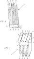
- eine Ansicht eines Ausführungsbeispiels eines ersten Kühlkörpers für ein elektronisches Bauelement wie ein Leistungsbauteil,
- Fig. 4
- eine Ansicht des ersten Kühlkörpers von unten mit einer in Längsrichtung des Kühlkörpers verlaufenden Aufnahmenut,
- Fig. 5
- eine Ansicht eines Ausführungsbeispiels eines zweiten Kühlkörpers für elektronische Bauelemente wie Leistungsbauteile,
- Fig. 6
- eine Ansicht des zweiten Kühlkörpers von unten mit einer in Längsrichtung des Kühlkörpers verlaufenden Aufnahmenut,
- Fig. 7
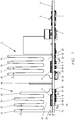
- in schematischer Darstellung einen Schnitt durch die Vorrichtung zur Abfuhr von Wärme von auf einer Platine angeordneten elektronischen Bauelementen wie Leistungsbauteilen und angeordneten Kühlkörpern nach
Fig. 1 , - Fig. 8
- in schematischer Darstellung einen Längsschnitt durch die Platine nach
Fig. 1 auf Höhe des ersten Kühlkörpers, - Fig. 9
- in schematischer Darstellung eine Ansicht von unten auf eine in einem Kühlkörper als Längsnut ausgebildete Ausnehmung mit in die Ausnehmung eingreifenden Zentrierelementen,
- Fig. 10
- eine Draufsicht auf ein rechteckiges Zentrierelement mit gerundeten Ecken,
- Fig. 11
- eine Draufsicht auf ein rechteckiges Zentrierelement mit gerundeten Stirnseiten,
- Fig. 12
- eine Seitenansicht eines Zentrierelementes nach den
Figuren 10 und 11 . - Die in
Fig. 1 gezeigte Platine 1 trägt insbesondere auf ihrer Platinenoberseite 2 eine Vielzahl von elektronischen Bauelementen 3, von denen einige elektronische Bauelemente 3 als Leistungsbauteile 7 bis 14 ausgebildet sind, sowie Steckanschlüsse 4 zur Verbindung mit weiteren elektronischen Baugruppen und/oder Kontaktzungen 44 zur Stromversorgung einer Last wie einem EC-Motor oder dergleichen. - Auf der Platine 1 sind Kühlkörper 5, 6 gehalten, die zur Wärmeabfuhr der Abwärme der elektronischen Bauelemente, insbesondere der elektronischen Leistungsbauteile 7 bis 14 vorgesehen sind. In
Fig. 2 sind die Leistungsbauteile 7 bis 11 in einer Reihe 15 angeordnet. Die Leistungsbauteile 12, 13 und 14 sind in einer Reihe 16 angeordnet. Im gezeigten Ausführungsbeispiel liegen die Reihen 15 und 16 zueinander parallel. Eine andere Anordnung kann zweckmäßig sein. - Die Vorrichtung zur Abfuhr von Wärme der auf der Platine 1 montierten elektronischen Bauelemente 3 mit einem Kühlkörper weist auf gegenüberliegenden Seiten zum Beispiel eines Leistungsbauteils 7 oder in der Platine ausgebildete Wärmeleitabschnitte 20, 21, 22 und 23 auf. Jedes elektronische Bauelement, insbesondere die Leistungsbauteile 7 bis 14 weisen jeweils auf einander gegenüberliegenden Seiten die insbesondere einteilig mit der Platine 1 ausgebildeten Wärmeleitabschnitte 20 bis 23 auf.
- Es kann zweckmäßig sein, mehreren Leistungsbauteilen 7, 8, 9, 10, 11 einen gemeinsamen Wärmeleitabschnitt 20 zuzuordnen, der sich längs der Reihe 15 der Leistungsbauteile 7 bis 11 erstreckt. Bevorzugt erstreckt sich ein Wärmeleitabschnitt über die gesamte Länge L1, L2 einer Reihe 10, 16 von Leistungsbauteilen. Insbesondere liegt der Wärmeleitabschnitt 20 und/oder 21 parallel zur Reihe 15 der Leistungsbauteile 7 bis 11. Vorteilhaft liegt der Wärmeleitabschnitt 22 und/oder 23 parallel zur Reihe 16 der Leistungsbauteile 12 bis 14.
- Es kann vorteilhaft sein, den einem elektronischen Bauelement bzw. einem elektronischen Leistungsbauteil zugeordneten Wärmeleitabschnitt getrennt von dem Wärmeleitabschnitt eines benachbarten Bauelementes bzw. Leistungsbauteils auszubilden. So besteht der in
Figur 2 gezeigte Wärmeleitabschnitt 21 aus vier Teilabschnitten 21a, 21b, 21c und 21d. Die Teilabschnitte 21a, 21b und 21c sind jeweils einem einzigen Leistungsbauteil 7, 8 bzw. 9 zugeordnet, während der Teilabschnitt 21d zwei benachbarten Leistungsbauteilen 10 und 11 zugeordnet ist. Der aus den Teilabschnitten 21a, 21b, 21c und 21d zusammengesetzte Wärmeleitabschnitt 21 hat eine Länge W1, die größer ist als die Länge L1 der Reihe der Leistungsbauteile 7 bis 11. - Entsprechend weist die Reihe 16 von elektronischen Bauelementen bzw. elektronischen Leistungsbauteilen 12, 13 und 14 auf einer Seite der Reihe 16 einen insbesondere durchgehenden gemeinsamen Wärmeleitabschnitt 23 auf. Auf der anderen Seite der Reihe 16 der Leistungsbauteile 12 bis 14 ist jedem Leistungsbauteil 12, 13 und 14 ein eigener Teilabschnitt 22a, 22b und 22c des Wärmeleitabschnitts 22 zugeordnet. Der aus den Wärmeleitabschnitten 22a, 22b und 22c zusammengesetzte Wärmeleitabschnitt 22 hat eine Länge W2, die größer als die Länge L2 der Reihe 16 ist.
- Die Länge W1 der Wärmeleitabschnitte 20 und 21 ist etwa 10% bis 30% länger als die Länge L1 der durch die Leistungsbauteile 7 bis 11 gebildeten Reihe 15. Die Länge W2 der Wärmeleitabschnitte 22 und 23 ist etwa 10% bis 30% länger als die Länge L2 der durch die Leistungsbauteile 12 bis 14 gebildeten Reihe 16.
- Jedes Leistungsbauteil 7 bis 14 weist eine Oberseite 17 und eine Unterseite 18 auf. Die Unterseite 18 des elektronischen Bauelementes bzw. des elektronischen Leistungsbauteils 7 bis 14 liegt auf der Platine 1 auf. Die Unterseite 18 des elektronischen Bauelementes bzw. des elektronischen Leistungsbauteils 7 bis 14 steht dabei in Wärme übertragender Verbindung mit der Platine 1 bzw. den Wärmeleitabschnitten 20, 21, 22 und 23 der Platine 1. Die Wärmeleitabschnitte 20, 21, 22 und 23 bestehen aus gut Wärme leitendem Material. Dieses Wärme leitende Material kann auf der Platine 1 aufgebracht, auf dieser befestigt und/oder in der Platine eingebettet sein.
- In den
Figuren 3 und 4 ist schematisch ein erster Kühlkörper 5 und in denFiguren 5 und 6 ein zweiter Kühlkörper 6 schematisch dargestellt. Jeder Kühlkörper besteht aus einem Grundkörper 25 mit daran angeordneten Kühlrippen 26, 27, 28 und 29. Die Kühlrippen 26, 27, 28 und 29 verlaufen in Längsrichtung des Grundkörpers 25 und liegen mit einem Abstand a zueinander. Die Kühlrippen 26, 27, 28 und 29 können gleich hoch ausgebildet sein; im gezeigten Ausführungsbeispiel hat die Kühlrippe 29 des Kühlkörpers 5 zumindest über eine Teillänge eine geringere Höhe als die übrigen Kühlrippen 26, 27 und 28. Der in denFiguren 5 und 6 dargestellte Kühlkörper 6 weist Kühlrippen gleicher Höhe auf. - Die Kühlkörper 5 und 6 haben einen gleichen Grundaufbau bestehend aus dem Grundkörper 25 und darauf angeordneten Kühlrippen 26 bis 29, wobei im Grundkörper 25 eine Ausnehmung 30 ausgebildet ist. Wie die
Figuren 4 und6 zeigen, erstreckt sich die Ausnehmung 30 vorteilhaft über die gesamte Länge K des Kühlkörpers 5. Die Ausnehmung 30 ist an ihren Enden 31 und 32 offen. Die Ausnehmung 30 bildet eine im Grundkörper 25 eingebrachte Aufnahmenut 33. - Der Grundkörper 25 des Kühlkörpers 5 bzw. 6 weist zwei Fußabschnitte 34 und 35 auf, die insbesondere als Fußstege ausgebildet sind und die Ausnehmung 30 bzw. die Aufnahmenut 33 begrenzen (
Fig. 4 ,6 und9 ). Die Fußabschnitte 34, 35 erstrecken sich vorzugsweise über die gesamte Länge K des Kühlkörpers 5 und haben eine Breite B1 bzw. B2 (Fig. 9 ), die der Breite Bw eines Wärmeleitabschnittes 20, 21, 22 und 23 angepasst ausgebildet ist. Für einen guten Wärmeübergang von einem Wärmeleitabschnitt 20, 21, 22 oder 23 auf den Kühlkörper 5 bzw. 6 ist es vorteilhaft, wenn die Breite B1 bzw. B2 des auf dem Wärmeleitabschnitt 20, 21, 22 und 23 aufstehenden Fußabschnittes 34 und 35 des Kühlkörpers zumindest der Breite Bw eines Wärmeleitabschnittes 20, 21, 22 und 23 entspricht. Bevorzugt beträgt die Breite B1 bzw. B2 des Fußabschnittes 34 bzw. 35 des Kühlkörpers 5 bzw. 6 insbesondere 80% bis 120% der Breite Bw des Wärmeleitabschnittes 20, 21, 22 oder 23. Vorteilhaft entspricht die Breite B1 bzw. B2 insbesondere 90% bis 110% der Breite Bw des Wärmeleitabschnittes. In einer vorteilhaften Ausführungsform ist die Breite B1 bzw. B2 mit 95% bis 105% der Breite Bw des Wärmeleitabschnittes gewählt. - Wie in den
Figuren 1 ,7 und8 gezeigt, werden die Kühlkörper 5 und 6 derart auf die Reihen 15 und 16 der Leistungsbauteile 7 bis 11 bzw. 12 bis 14 aufgesetzt, dass ihre Fußabschnitte 34 und 35 unmittelbar auf jeweils einem Wärmeleitabschnitt 20 und 21 bzw. 22 und 23 der Platine 1 aufstehen. Die Anordnung ist so getroffen, dass die elektronischen Leistungsbauteile 7 bis 11 der Reihe 15 bzw. die Leistungsbauteile 12 bis 14 der Reihe 16 in der jeweiligen Ausnehmung 30 des aufgesetzten Kühlkörpers 5 bzw. 6 aufgenommen sind. Vorteilhaft liegen alle Leistungsbauteile 7 bis 11 der Reihe 15 in einer gemeinsamen Ausnehmung 30 und/oder alle Leistungsbauteile 12 bis 14 der Reihe 16 in einer gemeinsamen Ausnehmung 30 des zugeordneten Kühlkörpers 5, 6. Die elektronischen Leistungsbauteile 7 bis 11 der Reihe 15 bzw. die Leistungsbauteile 12 bis 14 der Reihe 16 können in der Ausnehmung 30 vorzugsweise in Wärme übertragender Verbindung mit dem Kühlkörper 5 bzw. 6 stehen. - Es kann zweckmäßig sein, anstelle einer gemeinsamen Ausnehmung 30 im Kühlkörper 5, 6 für jedes Bauelement oder Leistungsbauteil eine getrennte Aufnahme auszubilden, so dass der Grundkörper eines Kühlkörpers 5, 6 mehrere einzelne, voneinander getrennte Aufnahmen aufweist. Die einzelnen Aufnahmen zu einer gemeinsamen Ausnehmung 30 auszubilden, ist eine vorteilhafte Ausführungsform der Erfindung.
- Wie die
Figuren 1 und7 zeigen, stehen die Fußabschnitte 34 und 35 eines Kühlkörpers 5 bzw. 6 auf gegenüberliegenden Seiten eines elektronischen Bauelementes bzw. eines Leistungsbauteils auf jeweils einem Wärmeleitabschnitt. Der Kühlkörper 5 bzw. 6 bildet somit eine Brücke, die das elektronische Bauelement bzw. das Leistungsbauteil 7 bis 14 übergreift. Die Anordnung ist dabei insbesondere so getroffen, dass die Fußabschnitte 34 und 35 eines Kühlkörpers 5 bzw. 6 unmittelbar auf den Wärmeleitabschnitten 20 und 21 bzw. 22 und 23 aufstehen. Es kann zweckmäßig sein, zwischen einem Fußabschnitt 34 und 35 eines Kühlkörpers 5 bzw. 6 und einem Wärmeleitabschnitt 20 und 21 bzw. 22 und 23 der Platine 1 ein wärmeleitendes Material anzuordnen. Ein derartiges wärmeleitendes Material kann in Form eines Pads, einer Wärmeleitpaste, eines Wärmeleitklebers oder dergleichen Material vorgesehen sein. - Der Kühlkörper 5 bzw. 6 steht mit seinen Fußabschnitten 34 und 35 mit den Wärmeleitabschnitten 20 und 21 bzw. 22 und 23 der Platine 1 in Wärme übertragender Verbindung. Vorteilhaft steht der Kühlkörper 5 bzw. 6 zugleich innerhalb der Ausnehmung 30 insbesondere zur Ableitung von Topwärme mit dem elektronischen Bauelement bzw. dem elektronischen Leistungsbauteil in Wärme übertragender Verbindung. Zweckmäßig liegt die Oberseite 17 eines Leistungsbauteils 7 bis 14 am Boden 36 der Ausnehmung 30 Wärme übertragend an. Vorteilhaft ist in einer Lücke u (
Fig. 8 ) zwischen der Oberseite 17 des Leistungsbauteils und dem Boden 36 der Ausnehmung 30 ein wärmeleitendes Material vorgesehen. Das wärmeleitende Material kann in Form eines Pads, einer Wärmeleitpaste, eines Wärmeleitklebers oder dergleichen Material vorgesehen sein. Ferner kann ein Gas (z. B. Luft) oder ein Vakuums vorgesehen sein, wobei der Wärmeübergang vom Bauelement auf den Kühlkörper über Konvektion oder Strahlung erfolgt. - Die Kühlkörper 5 und 6 bestehen aus einem gut wärmeleitenden Material. Ein gut wärmeleitendes Material ist oft elektrisch leitend. Daher muss sichergestellt werden, dass die Kühlkörper 5 und 6 bei der Montage auf die Leistungsbauteile 7 bis 14 keinen elektrischen Kontakt mit den Anschlussfähnchen der Leistungsbauteile haben. Nach der Erfindung ist vorgesehen, dass in die Ausnehmung 30 zumindest ein auf der Platine 1 festgelegtes Zentrierelement 40 eingreift. Das Zentrierelement 40 ist bestimmt und geeignet, den angeordneten Kühlkörper 5 bzw. 6 relativ zum elektronischen Bauelement bzw. dem Leistungsbauteil 7 bis 14 auszurichten. In Reihe mit zumindest einem elektronischen Bauelement bzw. Leistungsbauteil ist zumindest ein Zentrierelement 40 vorgesehen.
- Wie die
Figuren 2 und8 zeigen, ist im Anfangsabschnitt 37 und im Endabschnitt 38 einer Reihe 15 bzw. 16 der elektronischen Leistungsbauteile 7 bis 14 zumindest ein Zentrierelement 40 vorgesehen. In vorteilhafter Ausbildung bildet ein Zentrierelement 40 den Anfang und das Ende einer Reihe 15 bzw. 16 der Leistungsbauteile 7 bis 11 bzw. 12 bis 14. - Das Zentrierelement 40 ist im gezeigten Ausführungsbeispiel im Wesentlichen rechteckförmig gestaltet, wie insbesondere die
Figuren 9 bis 12 zeigen. Ein Zentrierelement 40 weist dabei eine Länge Z auf, die der quer zur Länge K (Fig. 9 ) des Kühlkörpers 5 bzw. 6 gemessenen Breite N der Ausnehmung 30 entspricht. Vorteilhaft ist die Länge Z des Zentrierelementes 40 kürzer als die Breite N der Ausnehmung 30. Vorteilhaft entspricht die Länge Z 90% bis 100% der Breite N der Ausnehmung. Insbesondere entspricht die Länge Z 95% bis 98% der Breite N der Ausnehmung 30. - Die Länge Z eines Zentrierelementes 40 entspricht derart der Breite N der Ausnehmung 30, dass ein in die Ausnehmung 30 eingreifendes Zentrierelement 40 geeignet ist, den Kühlkörper 5 bzw. 6 quer zur Längsrichtung eines elektronischen Bauelementes bzw. eines Leistungsbauteils 7 bis 14 oder einer Reihe 15 bzw. 16 der elektronischen Bauelemente bzw. der Leistungsbauteile 7 bis 14 auszurichten. Auf diese Weise wird ein elektrischer Kontakt des einen Leistungsbauteils 7 bis 14 übergreifenden Kühlkörpers 5 bzw. 6 mit den Anschlussfähnchen der Leistungsbauteile 7 bis 14 sicher vermieden.
- In besonderer Ausgestaltung der Erfindung ist vorgesehen, dass die Länge Z der Zentrierelemente 40 dem Abstand y (
Fig. 2 ) der einer Reihe 15 bzw. 16 zugeordneten Wärmeleitabschnitte 20, 21 bzw. 22, 23 entspricht. Bevorzugt entspricht die Länge Z des Zentrierelementes 40 insbesondere 95% bis 100% dem Abstand y der einem Leistungsbauteil 7 bis 14 zugeordneten Wärmeleitabschnitte 20, 21 bzw. 22, 23. - Ein durch den Kühlkörper 5 bzw. 6 zu kühlendes Leistungsbauteil 7 bis 14 hat eine Bauhöhe x (
Fig. 8 ). Alle Leistungsbauteile 7 bis 11 der Reihe 15 und alle Leistungsbauteile 12 bis 14 der Reihe 16 haben bevorzugt eine gleiche Bauhöhe x. Die Tiefe t der Ausnehmung 30 entspricht vorteilhaft der Bauhöhe x eines Leistungsbauteils; insbesondere ist die Tiefe t um 0,5% bis 2% tiefer als die Bauhöhe x eines Leistungsbauteils 7 bis 14. Die Tiefe t ist so bemessen, dass alle Leistungsbauteile einer Reihe 15 bzw. 16 mit ihrer Oberseite 17 - gegebenenfalls unter Einfügen eines wärmeleitfähigen Materials wie eines Pads, einer Wärmeleitpaste oder eines Wärmeleitklebers - mit dem Boden 36 der Ausnehmung 30 einen Wärme leitenden Kontakt haben. - Zur Ausrichtung eines Kühlkörpers 5, 6 auf der Platine 1 ist das Zentrierelement 40 auf der Platine 1 mechanisch festgelegt. Das Zentrierelement 40 weist eine Höhe c auf, die vorteilhaft der Tiefe t der Ausnehmung 30 im Kühlkörper 5 bzw. 6 entspricht oder zweckmäßig geringer als die Tiefe t ist. Wird in einer Weiterbildung der Erfindung die Tiefe t der Ausnehmung 30 im Kühlkörper 5 bzw. 6 insbesondere an die Bauhöhe x des elektronischen Bauelementes 3 bzw. des Leistungsbauteils 7 bis 14 angepasst, kann vorteilhaft erreicht werden, dass die Oberseite 17 eines Leistungsbauteils 7 bis 14 einen gut Wärme leitenden Kontakt mit dem Kühlkörper 5 bzw. 6 hat. Die Höhe c des Zentrierelementes 40 ist geringer oder gleich der Bauhöhe x des Leistungsbauteils 7 bis 14. Bevorzugt ist die Höhe c des Zentrierelementes 40 kleiner als die Bauhöhe x des Leistungsbauteils, so dass das Zentrierelement 40 lediglich der Funktion zur Ausrichtung des Kühlkörpers quer zur Reihe 15 bzw. 16 der Leistungsbauteile 7 bis 14 dient.
- Das Zentrierelement 40 kann die in
Fig. 10 strichliert dargestellte Rechteckform aufweisen. Sind die Zentrierplättchen 40 auf der Platine 1 positionsgenau montiert, ist ein Aufsetzen des Kühlkörpers 5 bzw. 6 auf das Zentrierelement 40 möglich. Werden die Ecken 41 des Zentrierelementes 40 gerundet, so wie dies inFig. 10 dargestellt ist, können Positionsabweichungen der Lageanordnung des Zentrierelementes 40 auf der Platine 1 ausgeglichen werden. Aufgrund der gerundeten Ecken des Zentrierelementes 40 nachFig. 10 ist auch bei unterschiedlichen Winkellagen der Zentrierelemente 40 in einer Reihe 15 bzw. 16 eine einfache Montage des Kühlkörpers 5 bzw. 6 gewährleistet. InFig. 9 ist dargestellt, wie mit angeordneten Zentrierelementen 40 einer Reihe eine ausreichende Lageausrichtung des Kühlkörpers 5 bzw. 6 durch die Zentrierelemente 40 einer Reihe 15 bzw. 16 erzielt wird. - In einer weiteren Ausbildung eines Zentrierelementes 40 nach
Fig. 11 ist vorgesehen, die Stirnseiten 42 des Zentrierelementes 40 gerundet auszuführen. Bevorzugt sind die Stirnseiten 42 als Halbkreisbögen ausgebildet. In besonderer Ausgestaltung eines Zentrierelementes 40 kann eine Stirnseite mit einem Radius R gerundet sein, der insbesondere der halben Länge Z eines Zentrierelementes 40 entspricht. Es kann vorteilhaft sein, den Radius R der Rundung einer Stirnseite auch größer auszubilden, z. B. in einem Bereich von einer halben Länge Z bis zu einem Mehrfachen von Z, z. B. der fünffachen Länge Z.
Claims (15)
- Vorrichtung zur Abfuhr von Wärme eines auf einer Platine (1) montierten elektronischen Bauelementes (3) mit einem Kühlkörper, insbesondere zur Abfuhr von Wärme eines elektronischen Leistungsbauteils (7 bis 14), wobei auf der Platine (1) zumindest ein Wärme abführender Wärmeleitabschnitt (20, 21, 22, 23) ausgebildet ist, und der Kühlkörper (5, 6) in Wärme übertragender Verbindung mit dem zumindest einen Wärmeleitabschnitt (20, 21, 22, 23) der Platine (1) steht,
dadurch gekennzeichnet, dass der Kühlkörper (5, 6) mit einem Fußabschnitt (34, 35) unmittelbar auf dem Wärmeleitabschnitt (20, 21, 22, 23) der Platine (1) aufsteht, dass im Grundkörper (25) des Kühlkörpers (5, 6) eine Ausnehmung (30) ausgebildet ist, und dass das elektronische Bauelement (3) zumindest teilweise in der Ausnehmung (30) liegt. - Vorrichtung nach Anspruch 1,
dadurch gekennzeichnet, dass der Kühlkörper (5, 6) auf einander gegenüberliegenden Seiten der Ausnehmung (30) mit je einem Fußabschnitt (34, 35) ausgebildet ist. - Vorrichtung nach Anspruch 2,
dadurch gekennzeichnet, dass die Platine (1) auf gegenüberliegenden Seiten des elektronischen Bauelementes (3) zumindest einen Wärmeleitabschnitt (20, 21, 22, 23) aufweist, wobei der Kühlkörper (5, 6) das elektronische Bauelement (3) als Brücke übergreift und mit je einem Fußabschnitt (34, 35) unmittelbar auf einem Wärmeleitabschnitt (20, 21; 22, 23) aufsteht. - Vorrichtung nach einem der Ansprüche 1 bis 3,
dadurch gekennzeichnet, dass mehrere elektronische Bauelemente (3) längs zumindest eines Wärmeleitabschnittes (20, 21, 22, 23) der Platine (1) in einer Reihe (15, 16) nebeneinander angeordnet sind, und den elektronischen Bauelementen (3) und den Wärmeleitabschnitten (20, 21, 22, 23) der Reihe (15, 16) ein gemeinsamer Kühlkörper (5, 6) zugeordnet ist. - Vorrichtung nach Anspruch 4,
dadurch gekennzeichnet, dass die elektronischen Bauelemente (3) der Reihe (15, 16) in einer gemeinsamen Ausnehmung (30) des Kühlkörpers (5, 6) liegen. - Vorrichtung nach einem der Ansprüche 1 bis 5,
dadurch gekennzeichnet, dass sich der Fußabschnitt (34, 35) des Kühlkörpers (5, 6) über die Länge eines elektronischen Bauelementes (3) oder über die Länge (L1, L2) der Reihe (15, 16) der elektronischen Bauelemente (3) erstreckt. - Vorrichtung nach einem der Ansprüche 1 bis 6,
dadurch gekennzeichnet, dass in die Ausnehmung (30) des Kühlkörpers (5, 6) zumindest ein auf der Platine (1) festgelegtes Zentrierelement (40) eingreift, das geeignet und bestimmt ist, den Kühlkörper (5, 6) relativ zum elektronischen Bauelement (3) auszurichten. - Vorrichtung nach Anspruch 7,
dadurch gekennzeichnet, dass in Reihe mit zumindest einem elektronischen Bauelement (3) das zumindest eine Zentrierelement (40) liegt. - Vorrichtung nach Anspruch 7 oder 8,
dadurch gekennzeichnet, dass quer zum Wärmeleitabschnitt (20, 21, 22, 23) die Länge (Z) eines Zentrierelementes (40) der Breite (Bw) der Ausnehmung (30) im Kühlkörper (5, 6) derart entspricht, dass ein in die Ausnehmung (30) eingreifendes Zentrierelement (40) geeignet ist, den Kühlkörper (5, 6) quer zur Längsrichtung des Wärmeleitabschnittes (20, 21, 22, 23) und des elektronischen Bauelementes (3) auszurichten. - Vorrichtung nach einem der Ansprüche 7 bis 9,
dadurch gekennzeichnet, dass das Zentrierelement (40) eine Höhe (c) aufweist, die geringer als oder gleich ist wie die Tiefe (t) der Ausnehmung (30) im Kühlkörper. - Vorrichtung nach einem der Ansprüche 7 bis 10,
dadurch gekennzeichnet, dass das Zentrierelement (40) mit gerundeten Ecken (41), insbesondere mit gerundeten Stirnseiten (42) ausgebildet ist. - Vorrichtung nach einem der Ansprüche 7 bis 11,
dadurch gekennzeichnet, dass im Anfangsabschnitt (37) und im Endabschnitt (38) einer Reihe (15, 16) von elektronischen Bauelemente (3) zumindest ein Zentrierelement (40) angeordnet ist. - Vorrichtung nach Anspruch 12,
dadurch gekennzeichnet, dass ein Zentrierelement (40) einen Anfang und ein Zentrierelement (40) ein Ende der Reihe (15, 16) der elektronischen Bauelemente (3) bildet. - Vorrichtung nach einem der Ansprüche 1 bis 13,
dadurch gekennzeichnet, dass das elektronische Bauelement (3) in der Ausnehmung (30) in Wärme übertragender Verbindung mit dem Kühlkörper (5, 6) steht. - Vorrichtung nach einem der Ansprüche 1 bis 14,
dadurch gekennzeichnet, dass das elektronische Bauelement (3) eine der Platine (1) zugewandte Unterseite (18) und eine von der Platine (1) abgewandte Oberseite (17) aufweist, wobei die Unterseite (18) des elektronischen Bauelementes (3) zur Abfuhr von Bottomwärme mit einem Wärmeleitabschnitt (20, 21, 22, 23) der Platine (1) in Wärme übertragender Verbindung steht, und die Oberseite (17) des elektronischen Bauelementes (3) zur Abfuhr von Topwärme mit dem Boden (36) der Ausnehmung (30) der Kühlkörpers (5, 6) in Wärme übertragender Verbindung steht.
Priority Applications (3)
| Application Number | Priority Date | Filing Date | Title |
|---|---|---|---|
| EP20183240.9A EP3933912A1 (de) | 2020-06-30 | 2020-06-30 | Kühlkörper für ein elektronisches leistungsbauteil |
| US17/352,539 US11632855B2 (en) | 2020-06-30 | 2021-06-21 | Arrangement for conducting heat away from an electronic component |
| CN202110732066.XA CN113873826A (zh) | 2020-06-30 | 2021-06-30 | 用于电子功率构件的冷却体 |
Applications Claiming Priority (1)
| Application Number | Priority Date | Filing Date | Title |
|---|---|---|---|
| EP20183240.9A EP3933912A1 (de) | 2020-06-30 | 2020-06-30 | Kühlkörper für ein elektronisches leistungsbauteil |
Publications (1)
| Publication Number | Publication Date |
|---|---|
| EP3933912A1 true EP3933912A1 (de) | 2022-01-05 |
Family
ID=71451976
Family Applications (1)
| Application Number | Title | Priority Date | Filing Date |
|---|---|---|---|
| EP20183240.9A Pending EP3933912A1 (de) | 2020-06-30 | 2020-06-30 | Kühlkörper für ein elektronisches leistungsbauteil |
Country Status (3)
| Country | Link |
|---|---|
| US (1) | US11632855B2 (de) |
| EP (1) | EP3933912A1 (de) |
| CN (1) | CN113873826A (de) |
Cited By (2)
| Publication number | Priority date | Publication date | Assignee | Title |
|---|---|---|---|---|
| WO2025261736A1 (de) * | 2024-06-19 | 2025-12-26 | Sew-Eurodrive Gmbh & Co Kg | Elektrogerät, insbesondere umrichter |
| DE102024139669A1 (de) | 2024-12-23 | 2026-06-25 | Andreas Stihl Ag & Co. Kg | Kühlkörper für einen Schaltungsträger einer Leistungskontrolleinheit |
Families Citing this family (2)
| Publication number | Priority date | Publication date | Assignee | Title |
|---|---|---|---|---|
| CN119155881A (zh) * | 2023-06-15 | 2024-12-17 | 台达电子工业股份有限公司 | 电子组件的散热结构 |
| TWI898918B (zh) * | 2024-11-08 | 2025-09-21 | 億光電子工業股份有限公司 | 電子組件 |
Citations (5)
| Publication number | Priority date | Publication date | Assignee | Title |
|---|---|---|---|---|
| US4888637A (en) * | 1988-01-15 | 1989-12-19 | Chrysler Motors Corporation | Multiple semiconductor heat sink/mounting assembly |
| WO2001033927A1 (en) * | 1999-11-02 | 2001-05-10 | Incep Technologies, Inc. | Inter-circuit encapsulated packaging for power delivery |
| US6882041B1 (en) * | 2002-02-05 | 2005-04-19 | Altera Corporation | Thermally enhanced metal capped BGA package |
| DE102010030525A1 (de) * | 2010-06-25 | 2011-12-29 | Zf Friedrichshafen Ag | Elektronische Steuerbaugruppe |
| DE102015210099A1 (de) * | 2015-02-10 | 2016-08-11 | Conti Temic Microelectronic Gmbh | Elektronische Komponente und Verfahren zur Herstellung einer solchen elektronischen Komponente |
Family Cites Families (19)
| Publication number | Priority date | Publication date | Assignee | Title |
|---|---|---|---|---|
| US4879629A (en) * | 1988-10-31 | 1989-11-07 | Unisys Corporation | Liquid cooled multi-chip integrated circuit module incorporating a seamless compliant member for leakproof operation |
| DE59709817D1 (de) * | 1996-02-23 | 2003-05-22 | Tyco Electronics Logistics Ag | Elektronische Schalteinrichtung, insbesondere elektronisches Relais, für Steckmontage |
| US6687126B2 (en) * | 2001-04-30 | 2004-02-03 | Hewlett-Packard Development Company, L.P. | Cooling plate arrangement for electronic components |
| DE10249436A1 (de) * | 2001-11-08 | 2003-05-22 | Tyco Electronics Amp Gmbh | Kühlkörper zur Kühlung eines Leistungsbauelements auf einer Platine |
| US7203065B1 (en) * | 2003-11-24 | 2007-04-10 | Ciena Corporation | Heatsink assembly |
| DE102005013762C5 (de) * | 2005-03-22 | 2012-12-20 | Sew-Eurodrive Gmbh & Co. Kg | Elektronisches Gerät und Verfahren zur Bestimmung der Temperatur eines Leistungshalbleiters |
| US20080001277A1 (en) * | 2006-06-30 | 2008-01-03 | Tsrong Yi Wen | Semiconductor package system and method of improving heat dissipation of a semiconductor package |
| DE102009002992B4 (de) * | 2009-05-11 | 2014-10-30 | Infineon Technologies Ag | Leistungshalbleitermodulanordnung mit eindeutig und verdrehsicher auf einem Kühlkörper montierbarem Leistungshalbleitermodul und Montageverfahren |
| US20110155360A1 (en) * | 2009-12-29 | 2011-06-30 | Kechuan Kevin Liu | Surface mount heat sink apparatus |
| US20110255250A1 (en) * | 2010-04-19 | 2011-10-20 | Richard Hung Minh Dinh | Printed circuit board components for electronic devices |
| DE102012013741B4 (de) * | 2011-08-02 | 2026-07-30 | Sew-Eurodrive Gmbh & Co Kg | Anordnung zum Kühlen, Elektrogerät und Verwendung einer Anordnung zum Kühlen |
| JP2013222861A (ja) * | 2012-04-17 | 2013-10-28 | Molex Inc | 冷却装置 |
| DE102012215673A1 (de) * | 2012-09-04 | 2014-03-06 | Zf Friedrichshafen Ag | Anordnung eines elektrischen Steuergeräts an eine Schaltplatte |
| DE102013001645A1 (de) * | 2013-01-31 | 2014-07-31 | Connaught Electronics Ltd. | Elektronisches Gerät mit verbesserter elektromagnetischer Verträglichkeit, Kamerasystem, Kraftfahrzeug und Verfahren zum Herstellen eines Gehäuses |
| US20150260390A1 (en) * | 2014-03-14 | 2015-09-17 | Eric Colin Bretschneider | Composite Heat Sink For Electrical Components |
| EP3483930B1 (de) * | 2017-11-10 | 2023-08-09 | Valeo Thermal Commercial Vehicles Germany GmbH | Elektronikbaueinheit |
| DE102018109920A1 (de) * | 2018-04-25 | 2019-10-31 | Dr. Ing. H.C. F. Porsche Aktiengesellschaft | Kühlung von leistungselektronischen Schaltungen |
| DE102018110754A1 (de) * | 2018-05-04 | 2019-11-07 | C. & E. Fein Gmbh | Elektronikeinheit |
| CN210405770U (zh) * | 2019-08-17 | 2020-04-24 | 深圳市金致卓科技有限公司 | 一种具有包边散热功能的电路板 |
-
2020
- 2020-06-30 EP EP20183240.9A patent/EP3933912A1/de active Pending
-
2021
- 2021-06-21 US US17/352,539 patent/US11632855B2/en active Active
- 2021-06-30 CN CN202110732066.XA patent/CN113873826A/zh active Pending
Patent Citations (5)
| Publication number | Priority date | Publication date | Assignee | Title |
|---|---|---|---|---|
| US4888637A (en) * | 1988-01-15 | 1989-12-19 | Chrysler Motors Corporation | Multiple semiconductor heat sink/mounting assembly |
| WO2001033927A1 (en) * | 1999-11-02 | 2001-05-10 | Incep Technologies, Inc. | Inter-circuit encapsulated packaging for power delivery |
| US6882041B1 (en) * | 2002-02-05 | 2005-04-19 | Altera Corporation | Thermally enhanced metal capped BGA package |
| DE102010030525A1 (de) * | 2010-06-25 | 2011-12-29 | Zf Friedrichshafen Ag | Elektronische Steuerbaugruppe |
| DE102015210099A1 (de) * | 2015-02-10 | 2016-08-11 | Conti Temic Microelectronic Gmbh | Elektronische Komponente und Verfahren zur Herstellung einer solchen elektronischen Komponente |
Cited By (2)
| Publication number | Priority date | Publication date | Assignee | Title |
|---|---|---|---|---|
| WO2025261736A1 (de) * | 2024-06-19 | 2025-12-26 | Sew-Eurodrive Gmbh & Co Kg | Elektrogerät, insbesondere umrichter |
| DE102024139669A1 (de) | 2024-12-23 | 2026-06-25 | Andreas Stihl Ag & Co. Kg | Kühlkörper für einen Schaltungsträger einer Leistungskontrolleinheit |
Also Published As
| Publication number | Publication date |
|---|---|
| CN113873826A (zh) | 2021-12-31 |
| US20210410271A1 (en) | 2021-12-30 |
| US11632855B2 (en) | 2023-04-18 |
Similar Documents
| Publication | Publication Date | Title |
|---|---|---|
| DE112018001743B4 (de) | Halbleitervorrichtung | |
| DE10251247B4 (de) | Halbleiterbaugruppe mit Halbleiterchip, gebildet unter Verwendung eines Halbleiters mit breitem Bandabstand als Basismaterial | |
| DE112018002547B4 (de) | Schaltungsvorrichtung | |
| DE102018132663B4 (de) | Schaltnetzteil | |
| DE102006045939A1 (de) | Leistungshalbleitermodul mit verbesserter Temperaturwechselstabilität | |
| DE3321321C2 (de) | ||
| DE102014115812B4 (de) | Halbleitermodul und Halbleitermodulanordnung mit geringen Kriechströmen | |
| DE112016003964T5 (de) | Leistungswandler | |
| DE4005333A1 (de) | Elektronischer leistungs-schalter | |
| DE3201296C2 (de) | Transistoranordnung | |
| DE19963883A1 (de) | Leistungshalbleiter-Gehäuse | |
| DE3017750C2 (de) | Halbleiterbauelement vom Planar-Epitaxial-Typ mit mindestens einem bipolaren Leistungstransistor | |
| EP1764832B1 (de) | Bondverbindung für Leistungshalbleiterbauelemente | |
| EP2414725B1 (de) | Led-lichtquelle mit einer vielzahl von led-chips und led-chip zur verwendung in selbiger | |
| EP2162912B1 (de) | Halbleiterbauelement mit ringförmig geschlossener kontaktierung | |
| DE102021207316A1 (de) | Leistungselektronik | |
| EP3432692B1 (de) | Thermische kopplung von kupferspreizflächen | |
| EP1393375A1 (de) | Kontaktanordnung | |
| DE102016203819B4 (de) | Halbleitermodul und Halbleitervorrichtung | |
| EP0001548A1 (de) | Hochleistungsstromrichter mit gekühlten parallelgeschalteten Stromrichterventilen | |
| EP4033867B1 (de) | Elektrische schaltvorrichtung | |
| DE102022205513A1 (de) | Halbbrückenmodul mit isolierten Anschlussflächen zwischen zwei Transistor-Streifenabschnitten | |
| DE102023210040A1 (de) | Leistungselektronik-Kühler zur Kühlung einer Leistungselektronikvorrichtung, Leistungselektronikvorrichtung und Inverter | |
| DE102023131251A1 (de) | Leiterplattenanordnung und Verfahren zu dessen Herstellung | |
| DE20300479U1 (de) | Leistungs-Halbleiter und Anordnung mit einem solchen |
Legal Events
| Date | Code | Title | Description |
|---|---|---|---|
| PUAI | Public reference made under article 153(3) epc to a published international application that has entered the european phase |
Free format text: ORIGINAL CODE: 0009012 |
|
| STAA | Information on the status of an ep patent application or granted ep patent |
Free format text: STATUS: THE APPLICATION HAS BEEN PUBLISHED |
|
| AK | Designated contracting states |
Kind code of ref document: A1 Designated state(s): AL AT BE BG CH CY CZ DE DK EE ES FI FR GB GR HR HU IE IS IT LI LT LU LV MC MK MT NL NO PL PT RO RS SE SI SK SM TR |
|
| B565 | Issuance of search results under rule 164(2) epc |
Effective date: 20201127 |
|
| STAA | Information on the status of an ep patent application or granted ep patent |
Free format text: STATUS: REQUEST FOR EXAMINATION WAS MADE |
|
| 17P | Request for examination filed |
Effective date: 20220627 |
|
| RBV | Designated contracting states (corrected) |
Designated state(s): AL AT BE BG CH CY CZ DE DK EE ES FI FR GB GR HR HU IE IS IT LI LT LU LV MC MK MT NL NO PL PT RO RS SE SI SK SM TR |
|
| STAA | Information on the status of an ep patent application or granted ep patent |
Free format text: STATUS: EXAMINATION IS IN PROGRESS |
|
| 17Q | First examination report despatched |
Effective date: 20260612 |