EP3933539B1 - Autonom führbarer fahrzeugzug - Google Patents
Autonom führbarer fahrzeugzug Download PDFInfo
- Publication number
- EP3933539B1 EP3933539B1 EP21176995.5A EP21176995A EP3933539B1 EP 3933539 B1 EP3933539 B1 EP 3933539B1 EP 21176995 A EP21176995 A EP 21176995A EP 3933539 B1 EP3933539 B1 EP 3933539B1
- Authority
- EP
- European Patent Office
- Prior art keywords
- vehicle
- lead
- following
- following vehicle
- train
- Prior art date
- Legal status (The legal status is an assumption and is not a legal conclusion. Google has not performed a legal analysis and makes no representation as to the accuracy of the status listed.)
- Active
Links
Images


Classifications
-
- G—PHYSICS
- G05—CONTROLLING; REGULATING
- G05D—SYSTEMS FOR CONTROLLING OR REGULATING NON-ELECTRIC VARIABLES
- G05D1/00—Control of position, course, altitude or attitude of land, water, air or space vehicles, e.g. using automatic pilots
- G05D1/02—Control of position or course in two dimensions
- G05D1/021—Control of position or course in two dimensions specially adapted to land vehicles
- G05D1/0287—Control of position or course in two dimensions specially adapted to land vehicles involving a plurality of land vehicles, e.g. fleet or convoy travelling
- G05D1/0291—Fleet control
- G05D1/0295—Fleet control by at least one leading vehicle of the fleet
-
- G—PHYSICS
- G05—CONTROLLING; REGULATING
- G05D—SYSTEMS FOR CONTROLLING OR REGULATING NON-ELECTRIC VARIABLES
- G05D1/00—Control of position, course, altitude or attitude of land, water, air or space vehicles, e.g. using automatic pilots
- G05D1/02—Control of position or course in two dimensions
- G05D1/021—Control of position or course in two dimensions specially adapted to land vehicles
- G05D1/0287—Control of position or course in two dimensions specially adapted to land vehicles involving a plurality of land vehicles, e.g. fleet or convoy travelling
- G05D1/0291—Fleet control
- G05D1/0293—Convoy travelling
-
- B—PERFORMING OPERATIONS; TRANSPORTING
- B60—VEHICLES IN GENERAL
- B60R—VEHICLES, VEHICLE FITTINGS, OR VEHICLE PARTS, NOT OTHERWISE PROVIDED FOR
- B60R19/00—Wheel guards; Radiator guards, e.g. grilles; Obstruction removers; Fittings damping bouncing force in collisions
- B60R19/02—Bumpers, i.e. impact receiving or absorbing members for protecting vehicles or fending off blows from other vehicles or objects
- B60R19/18—Bumpers, i.e. impact receiving or absorbing members for protecting vehicles or fending off blows from other vehicles or objects characterised by the cross-section; Means within the bumper to absorb impact
- B60R19/20—Bumpers, i.e. impact receiving or absorbing members for protecting vehicles or fending off blows from other vehicles or objects characterised by the cross-section; Means within the bumper to absorb impact containing mainly gas or liquid, e.g. inflatable
-
- G—PHYSICS
- G05—CONTROLLING; REGULATING
- G05D—SYSTEMS FOR CONTROLLING OR REGULATING NON-ELECTRIC VARIABLES
- G05D1/00—Control of position, course, altitude or attitude of land, water, air or space vehicles, e.g. using automatic pilots
- G05D1/02—Control of position or course in two dimensions
- G05D1/021—Control of position or course in two dimensions specially adapted to land vehicles
- G05D1/0276—Control of position or course in two dimensions specially adapted to land vehicles using signals provided by a source external to the vehicle
-
- G—PHYSICS
- G05—CONTROLLING; REGULATING
- G05D—SYSTEMS FOR CONTROLLING OR REGULATING NON-ELECTRIC VARIABLES
- G05D1/00—Control of position, course, altitude or attitude of land, water, air or space vehicles, e.g. using automatic pilots
- G05D1/02—Control of position or course in two dimensions
- G05D1/021—Control of position or course in two dimensions specially adapted to land vehicles
- G05D1/0287—Control of position or course in two dimensions specially adapted to land vehicles involving a plurality of land vehicles, e.g. fleet or convoy travelling
- G05D1/0289—Control of position or course in two dimensions specially adapted to land vehicles involving a plurality of land vehicles, e.g. fleet or convoy travelling with means for avoiding collisions between vehicles
Definitions
- the present invention relates to an autonomously driven vehicle train and a method for autonomously driving a vehicle train.
- RCVA rigidly coupled vehicle assembly
- IVs independent vehicles
- the IVs include, for example, a propulsion system and a steering system.
- the improved concept is based on the idea of providing a self-propelled leader vehicle in a vehicle train and at least two follower vehicles that can be coupled to one another and one of which can be coupled to the leader vehicle. The following vehicles then follow the self-driving lead vehicle.
- an autonomously driven vehicle train contains a self-propelled first lead vehicle, a first follower vehicle and a second follower vehicle.
- the vehicle train contains a first coupling unit which is designed to couple the first follower vehicle and the first lead vehicle to one another.
- the vehicle train contains a second coupling unit which is designed to couple the second following vehicle and the first following vehicle to one another.
- the first follower vehicle has a first drive system and a first control unit, wherein the first control unit is set up to automatically control the first drive system so that the first follower vehicle follows the first lead vehicle when the first follower vehicle and the first lead vehicle are coupled to one another.
- the second follower vehicle has a second drive system and a second control unit, wherein the second control unit is set up to automatically control the second drive system so that the second follower vehicle follows the first follower vehicle, and thus indirectly the first lead vehicle, when the second follower vehicle and the first following vehicle are coupled to each other.
- a vehicle train can be understood to mean a combination of at least three vehicles that are guided along a common route or trajectory.
- the at least three vehicles include the first leader vehicle and the first and second follower vehicles.
- a self-driving vehicle in particular the self-driving first lead vehicle, can be understood here and below to mean a motor vehicle that is set up to be guided fully autonomously or fully automatically, and in particular unmanned and without remote control by a human person and without following a reference vehicle can.
- a self-driving vehicle can accordingly also be referred to as a robot vehicle.
- the self-driving vehicle carries out all necessary functions, such as any required steering, braking and/or acceleration maneuvers, observation and detection of traffic and the associated necessary reactions, automatically and fully automatically.
- the self-driving vehicle can be designed as a vehicle according to level 5 of the classification according to SAE J3016.
- SAE J3016 refers to the corresponding standard in the June 2018 version.
- the following vehicles are in particular designed to be driven without direct control or remote control by a human.
- the following vehicles can are therefore viewed as at least partially automated or semi-autonomous motor vehicles.
- the following vehicles are not designed as self-driving vehicles.
- the following vehicles are dependent on the guidance of another vehicle. This can be done, for example, by a self-driving vehicle or by another follow-up vehicle.
- the coupling of two vehicles to one another through the respective coupling unit can be understood here and below to mean that the respective coupling unit enables an exchange of force and/or information between the respective vehicles coupled to one another, so that based on the exchanged force and/or the information exchanged by one of the vehicles can follow the other vehicle. It is irrelevant whether the vehicle being followed is following another vehicle or whether the vehicle being followed is a self-driving vehicle.
- a drive system can be understood in particular as a system with a drive motor for the respective vehicle.
- the drive system can also include a braking system of the respective vehicle and/or a steering system of the respective vehicle.
- the steering system and/or braking system of the respective vehicle can also be designed separately from the drive system.
- a following vehicle does not necessarily have a steering system, but this can be the case in various embodiments of the vehicle train
- the respective control unit can therefore control the corresponding drive system and optionally the corresponding braking and/or steering system of the respective following vehicle in such a way that a longitudinal speed and optionally a steering angle of the respective following vehicle is adapted to the current behavior of the first lead vehicle or first follower vehicle in front, or, in other words, the behavior of the first lead vehicle or first follower vehicle in front is adjusted or imitated.
- the first follower vehicle also carries out or approximately carries out vehicle guidance maneuvers that the first lead vehicle carries out, if necessary with a time delay. This applies analogously to the second following vehicle in order to follow the first following vehicle.
- the improved concept in order to realize an autonomously drivable vehicle train, only the first lead vehicle has to be designed as a self-driving vehicle, whereas the follower vehicles only have to be designed so that they can follow another vehicle.
- significantly reduced effort is required for the following vehicles in terms of the sensor systems, other hardware and software systems and/or safety systems to be provided. This means that costs can be saved for the entire vehicle train.
- a further advantage of the improved concept is that the specific design of the following vehicles can be flexible and can in particular vary depending on the application of the following vehicle. For example, follow-up vehicles for transporting people, follow-up vehicles for providing services and so on can be used equally. It is also possible, but not necessary, for all following vehicles in the vehicle train to have the same design.
- Another advantage of the improved concept is that, due to the above-mentioned reduced effort for sensor systems and hardware of the following vehicles, the installation space of the following vehicles can be reduced or the installation space is available for other components or purposes.
- the vehicle train contains a self-propelled second lead vehicle.
- the statements made regarding the first lead vehicle can be transferred analogously to the second lead vehicle.
- the vehicle train can contain a large number of vehicles which are arranged one behind the other when driving the vehicle train autonomously.
- the plurality of vehicles includes the first and second lead vehicles as well as the first and second follower vehicles and can optionally include one or more further follower vehicles.
- the lead vehicles and the following vehicles are arranged in such a way that the first and the second following vehicle are located and the other following vehicles are located between the first and second lead vehicle.
- the first leader vehicle represents a first vehicle of the vehicle train and the second leader vehicle represents a last vehicle of the vehicle train or vice versa.
- the lead vehicles and, if applicable, the follower vehicles can be set up in such a way that a reversal of direction is also possible, so that the first and second lead vehicle, depending on the direction of movement of the vehicle train, each act as the first vehicle without changing the arrangement of the follower vehicles and the lead vehicles within the vehicle train of the vehicle train as well as the last vehicle in the vehicle train.
- each further follower vehicle has at least one further follower vehicle, a corresponding drive system and a corresponding control unit, which can control the respective drive system in such a way that it can follow the follower vehicle or lead vehicle in front.
- the vehicle train contains a third coupling unit which is designed to couple the second follower vehicle and the second lead vehicle to one another.
- the vehicle train contains a further coupling unit which is designed to couple the at least one further following vehicle, in particular a further following vehicle following the second following vehicle, to one another.
- the savings stated above with regard to the requirements for sensors, hardware and software and thus the corresponding cost savings are even greater.
- the greater the number of following vehicles in the vehicle train the greater the respective savings.
- the vehicle train contains the second self-propelled lead vehicle as well as the at least one follower vehicle and a further third coupling unit.
- the further third coupling unit is set up to provide a final one To couple the follower vehicle of the at least one further follower vehicle and the second lead vehicle to one another.
- the first lead vehicle in particular the brake system of the first lead vehicle, has a brake actuator and a brake control unit, wherein the brake control unit is set up to actuate the brake actuator, in particular automatically.
- the first host vehicle has a communication interface that is set up to wirelessly transmit an information signal to the second host vehicle, in particular a communication interface of the second leader vehicle, depending on the actuation of the brake actuator by the brake control unit.
- the second lead vehicle can react more quickly to a braking maneuver of the first lead vehicle and thus, for example, more reliably maintain a safety distance between the second lead vehicle and the final follower vehicle, or, if the vehicle train does not have at least one further follower vehicle, the second follower vehicle.
- the second lead vehicle can be designed in accordance with the first lead vehicle with regard to the braking system.
- the first control vehicle contains a safety system that is set up to detect the existence of an accident situation.
- the safety system contains an impact protection element and a triggering unit, the triggering unit being set up to activate the impact protection element when the existence of the accident situation has been detected.
- the activated impact protection element is in particular designed or arranged in the activated state in such a way that the first following vehicle colliding with the first leading vehicle can be prevented or dampened.
- the first lead vehicle takes over safety functions of the vehicle train. This allows the necessary requirements for the safety systems of the following vehicles and, accordingly, the costs of the entire vehicle train to be reduced. In addition, the installation space of the following vehicles can be reduced or made available for other purposes.
- the second lead vehicle can, for example, be designed in accordance with the first lead vehicle in terms of the safety system.
- the impact protection element is at least partially arranged between the first lead vehicle and the first follower vehicle when the impact protection element has been activated.
- the impact protection element of which is then at least partially located between the second leading element and the final following vehicle or the second following vehicle when activated.
- the safety system includes an airbag system.
- the impact protection element contains an impact cushion.
- the trigger unit is designed to introduce a gas into the impact cushion in order to activate the impact protection element.
- the first coupling unit contains an environment sensor system that is set up to generate at least one sensor signal that represents an area between the first lead vehicle and the first follower vehicle.
- the first control unit is set up to control the first drive system depending on the at least one sensor signal, so that the first follower vehicle follows the first lead vehicle.
- the environment sensor system is coupled to the first control unit in a wired or wireless manner in order to transmit the at least one sensor signal to the first control unit; the environment sensor system can be on the first leading vehicle, in particular on a side of the first leading vehicle facing the first following vehicle, or on the first Follow vehicle, in particular a side of the first follow vehicle facing the first lead vehicle, may be arranged. In various embodiments, one or more components of the environment sensor system can be arranged on the first lead vehicle and one or more further components of the environment sensor system can be arranged on the first follower vehicle.
- the environment sensor system can in particular have one or more cameras, one or more radar systems, one or more lidar systems, one or more other active optical sensor systems, one or more ultrasonic sensor systems and/or one or more other distance sensor systems.
- the first control unit can, in particular depending on the at least one sensor signal, control the first drive system, and optionally the braking system and/or steering system of the first following vehicle, such that the distance between the first leading vehicle and the first following vehicle is in a predetermined range, so that the first The following vehicle follows the first leading vehicle.
- the environment sensor system of the first coupling unit By using the environment sensor system of the first coupling unit, it is possible in particular to dispense with mechanical or physical connections between the first follower vehicle and the first lead vehicle or to make them simpler. In addition, without a mechanical or physical connecting element, it is not necessary for manual steps to be taken to couple the first host vehicle and the first follower vehicle, for example by a human user.
- first coupling unit can be transferred analogously to all other coupling units of the vehicle train, in particular to the second and third coupling units as well as the further coupling unit.
- the first lead vehicle and the first follower vehicle must then be replaced by the correspondingly adjacent or coupled vehicles.
- different coupling units of the vehicle train can be designed the same or different from one another.
- the first control unit is set up to regulate a distance between the first lead vehicle and the first follower vehicle so that the distance lies within a predetermined distance range and/or so that the distance is greater than or equal to a predetermined minimum distance.
- the distance can be regulated in particular by controlling or regulating the first drive system and optionally the braking system and/or the steering system of the first following vehicle. This can further increase security.
- the first coupling unit contains a mechanical connecting element which is designed to connect the first lead vehicle to the first follower vehicle in order to couple the first lead vehicle and the first follower vehicle to one another.
- the mechanical connecting element can be provided in addition to or as an alternative to the environment sensor system of the first coupling unit.
- the requirements for the environment sensor system and the evaluation of the at least one sensor signal of the environment sensor system can be reduced or, if necessary, the environment sensor system can be completely dispensed with, which in turn leads to savings in installation space and costs for the vehicle train.
- the first coupling unit contains a force sensor which is set up and arranged to generate a force sensor signal depending on a force transmitted by the mechanical connecting element between the first leading vehicle and the first following vehicle.
- the first control unit is set up to control the first drive system depending on the force sensor signal, in particular so that the first follower vehicle follows the first lead vehicle.
- the first lead vehicle and/or the second lead vehicle are designed as a single-axle, self-balancing vehicle.
- a method for autonomously driving a vehicle train is also specified.
- the vehicle train contains a first self-propelled lead vehicle, a first follower vehicle and a second follower vehicle.
- the first follower vehicle and the first lead vehicle are coupled to one another, in particular by means of a first coupling unit.
- the second following vehicle and the first following vehicle are coupled to one another, in particular by means of a second coupling unit.
- the first follower vehicle is automatically controlled so that the first follower vehicle follows the first leader vehicle when the first follower vehicle and the first leader vehicle are coupled to one another.
- the second following vehicle is automatically controlled so that the second following vehicle follows the first following vehicle when the second following vehicle and the first following vehicle are coupled to one another.
- the first lead vehicle is guided autonomously, i.e. in particular fully automatically, from a starting position to a predetermined target position.
- the first follower vehicle and the second follower vehicle then follow the first lead vehicle accordingly from respective positions corresponding to the starting position to the respective position corresponding to the target position.
- FIG. 1 an exemplary embodiment of an autonomously driven vehicle train 1 according to the improved concept is shown schematically.
- the vehicle train 1 has a self-propelled first lead vehicle 2a, a first follower vehicle 3a coupled thereto and a second follower vehicle 3b coupled to the first follower vehicle 3a.
- the vehicle train 1 contains a first coupling unit 4a for coupling the first leading vehicle 2a with the first following vehicle 3b and a second coupling unit 4b for coupling the first following vehicle 3a with the second following vehicle 3b.
- the first and second follower vehicles 3a, 3b contain a first drive system 5a and a second drive system 5b as well as a first control unit 6a and a second control unit 6b.
- the coupling units 4a, 4b can be designed as virtual coupling units or as physical coupling units or as a combination of the two options.
- a virtual coupling unit contains an environmental sensor system, such as one or more cameras, ultrasonic sensors, radar systems or laser distance sensors.
- a physical coupling unit contains one or more mechanical connecting elements for mechanically connecting the lead vehicle 2a to the first follower vehicle 3a. The same applies to the second coupling unit 4b.
- the first lead vehicle 2a is guided fully autonomously from a starting position to a predetermined target position, for example by an electronic vehicle guidance system (not shown) of the first lead vehicle 2a.
- the first control unit 6a is set up to control the first drive system 5a such that the first follower vehicle 3a follows the first lead vehicle 2a during its autonomous journey.
- the second control unit 6b is set up to control the second drive system 5b, so that the second follower vehicle 3b follows the first follower vehicle 3a and thus indirectly also the first lead vehicle 2a.
- the first lead vehicle 2a can be designed in various embodiments as a single-axle, self-balancing vehicle.
- the first lead vehicle 2a and/or the first follower vehicle 3a in particular via the first coupling unit 4a, can ensure that a predetermined safety distance between the first lead vehicle 2a and the first follower vehicle 3a is maintained.
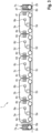
- a further exemplary embodiment of a vehicle train 1 according to the improved concept is shown schematically, the vehicle train 1 being the Fig. 2 on the one of Fig. 1 based.
- the vehicle train 1 of the Fig. 2 also has three further following vehicles 3c, 3d, 3e, the further following vehicle 3c being coupled to the second following vehicle 3b by means of a coupling unit 4c, the further following vehicle 3d being coupled to the following vehicle 3c by means of a coupling unit 4d and the following vehicle 3e being coupled by means of a coupling unit 4e is coupled to the following vehicle 3d.
- the vehicle train 1 has a second self-propelled leader vehicle 2b, which can be designed analogously to the first self-propelled leader vehicle 2a.
- the following vehicles 3a, 3b, 3c, 3d, 3e can be arranged between the first leader vehicle 2a and the second leader vehicle 2b during operation of the vehicle train 1.
- the second leading vehicle 2b is coupled to the following vehicle 3e by means of a coupling unit 4f.
- the other following vehicles 3c, 3d, 3e also have, as described with regard to the following vehicles 3a, 3b, corresponding drive systems 5c, 5d, 5e and control units 4c, 4d, 4e that control them. It is noted that the number of following vehicles in Fig. 2 is only chosen as an example and can also assume different values.
- the further lead vehicle 2b can, for example, be set up, for example by means of the coupling unit 4f, to maintain a safety distance between the follower vehicle 3e and the second lead vehicle 2b.
- the lead vehicles 2a, 2b can each have a communication interface 7a, 7b.
- the control vehicles 2a, 2b can communicate with each other wirelessly via the communication interface 7a, 7b.
- a corresponding information signal can be transmitted to the communication interface 7b of the second lead vehicle 2b by means of the communication interface 7a of the first lead vehicle 2a.
- the second lead vehicle 2b can then react accordingly to the braking action of the first lead vehicle 2a and in particular maintain the safety distance.
- the further coupling units 4c, 4d, 4e, 4f can in particular be designed as was explained with regard to the coupling units 4a, 4b.
- FIG. 3 A further exemplary embodiment of a vehicle train according to the improved concept is shown, the vehicle train 1 being the Fig. 3 on vehicle train 1 of the Fig. 2 based.
- the lead vehicles 2a, 2b of the vehicle train 1 Fig. 3 each have a security system 8a, 8b.
- the safety systems 8a, 8b can be designed, for example, as airbag systems, with corresponding impact cushions being filled with gas when an acceleration sensor or other triggering unit of the corresponding lead vehicle 2a detects the existence of an accident or a high probability of the existence of an accident. This can further increase security.
- Fig. 4A shows vehicle train 1 of the Fig. 3 schematically in a situation in which the first lead vehicle 2a is involved in an accident or has initiated emergency braking. Furthermore, the impact cushion 9 of the safety system 8a is shown in the activated state, i.e. in the gas-filled state. The gas-filled impact cushion 9 is then located between the first leading vehicle 2a and the first following vehicle 3a in order to prevent damage to the first leading vehicle 2a and/or the first following vehicle 3a due to the first following vehicle 3a colliding with the first leading vehicle 2a.
- Fig. 4A are the first lead vehicle 2a and the first follower vehicle 3a of the vehicle train 1 Fig. 3 or the Fig. 4a shown in a top view.
- the improved concept offers a possibility of realizing an autonomously driven vehicle train with lower requirements for sensor systems, hardware and software units to be provided.
- the improved concept achieves increased flexibility in terms of dimensions and functions, particularly for the following vehicles.
- the number of following vehicles can be increased as desired in order to achieve further energy savings.
- the lead vehicle or the lead vehicles also take over safety functions for the following vehicles. Therefore, less stringent requirements for crumple zones of the following vehicles may have to be met, which allows a simpler design of the following vehicles.
Landscapes
- Engineering & Computer Science (AREA)
- Radar, Positioning & Navigation (AREA)
- Remote Sensing (AREA)
- Aviation & Aerospace Engineering (AREA)
- Physics & Mathematics (AREA)
- General Physics & Mathematics (AREA)
- Automation & Control Theory (AREA)
- Mechanical Engineering (AREA)
- Electric Propulsion And Braking For Vehicles (AREA)
- Traffic Control Systems (AREA)
- Control Of Driving Devices And Active Controlling Of Vehicle (AREA)
Description
- Die vorliegende Erfindung betrifft einen autonom führbaren Fahrzeugzug sowie ein Verfahren zum autonomen Führen eines Fahrzeugzugs.
- Aus dem Stand der Technik sind vollautonom betreibbare, also selbstfahrende, Kraftfahrzeuge bekannt. Damit diese vollständig ohne menschliche Steuerung beziehungsweise ohne Unterstützung durch ein weiteres Fahrzeug betrieben werden können, ist eine umfangreiche Ausstattung des selbstfahrenden Kraftfahrzeugs mit Sensorsystemen aller Art, leistungsfähigen Recheneinheiten sowie Softwaresystemen erforderlich. Vor allem wenn mehrere Kraftfahrzeuge autonom betrieben werden sollen, stellt dies einen enormen Entwicklungs- und Kostenaufwand dar. Außerdem wird ein signifikanter Teil des Bauraums durch die Ausstattung belegt.
- Dokument
US 2018/0022405 A1 beschreibt eine starr gekoppelte Fahrzeugbaugruppe ("RCVA"), die durch mehrere unabhängige Fahrzeuge ("IVs"), die miteinander gekoppelt sind, gebildet wird. Jedes der IVs kann ein selbstfahrendes autonomes Fahrzeug sein. Die IVs umfassen beispielsweise ein Antriebssystem und ein Lenksystem. - Vor diesem Hintergrund ist es eine Aufgabe der vorliegenden Erfindung, ein verbessertes Konzept zum autonomen Führen eines Fahrzeugzuges anzugeben, durch das insgesamt die Anforderungen an die Ausstattung der Fahrzeuge des Fahrzeugzuges reduziert werden können.
- Diese Aufgabe wird gelöst durch den jeweiligen Gegenstand der unabhängigen Ansprüche. Vorteilhafte Weiterbildungen und bevorzugte Ausführungsformen sind Gegenstand der abhängigen Ansprüche.
- Das verbesserte Konzept basiert auf dem Gedanken, bei einem Fahrzeugzug ein selbstfahrendes Leitfahrzeug vorzusehen und wenigstens zwei Folgefahrzeuge, die aneinander koppelbar sind und von denen eines an das Leitfahrzeug koppelbar ist. Die Folgefahrzeuge folgen dann dem selbstfahrenden Leitfahrzeug.
- Gemäß dem verbesserten Konzept wird ein autonom führbarer Fahrzeugzug angegeben. Der Fahrzeugzug enthält ein selbstfahrendes erstes Leitfahrzeug, ein erstes Folgefahrzeug und ein zweites Folgefahrzeug. Der Fahrzeugzug enthält eine erste Koppeleinheit, die dazu eingerichtet ist, das erste Folgefahrzeug und das erste Leitfahrzeug aneinander zu koppeln. Der Fahrzeugzug enthält eine zweite Kopplungseinheit, die dazu eingerichtet ist, das zweite Folgefahrzeug und das erste Folgefahrzeug aneinander zu koppeln. Das erste Folgefahrzeug weist ein erstes Antriebssystem auf sowie eine erste Steuereinheit, wobei die erste Steuereinheit dazu eingerichtet ist, das erste Antriebssystem automatisch so anzusteuern, dass das erste Folgefahrzeug dem ersten Leitfahrzeug folgt, wenn das erste Folgefahrzeug und das erste Leitfahrzeug aneinander gekoppelt sind. Das zweite Folgefahrzeug weist ein zweites Antriebssystem und eine zweite Steuereinheit auf, wobei die zweite Steuereinheit dazu eingerichtet ist, das zweite Antriebssystem automatisch so zu steuern, dass das zweite Folgefahrzeug dem ersten Folgefahrzeug folgt, und damit indirekt dem ersten Leitfahrzeug, wenn das zweite Folgefahrzeug und das erste Folgefahrzeug aneinander gekoppelt sind.
- Unter einem Fahrzeugzug kann hier und im Folgenden ein Verbund aus wenigstens drei Fahrzeugen verstanden werden, die entlang einer gemeinsamen Strecke oder Trajektorie geführt werden. Gemäß dem verbesserten Konzept enthalten die wenigstens drei Fahrzeuge das erste Leitfahrzeug sowie das erste und das zweite Folgefahrzeug.
- Unter einem selbstfahrenden Fahrzeug, insbesondere unter dem selbstfahrenden ersten Leitfahrzeug, kann hier und im Folgenden ein Kraftfahrzeug verstanden werden, das dazu eingerichtet ist, vollautonom oder vollautomatisch, und insbesondere unbemannt sowie ohne Fernsteuerung durch eine menschliche Person und ohne einem Referenzfahrzeug zu folgen, geführt werden kann. Ein selbstfahrendes Fahrzeug kann dementsprechend auch als Roboterfahrzeug bezeichnet werden. Das selbstfahrende Fahrzeug führt alle erforderlichen Funktionen, wie gegebenenfalls erforderliche Lenk-, Brems- und/oder Beschleunigungsmanöver, die Beobachtung und Erfassung des Verkehrs sowie die damit verbundenen erforderlichen Reaktionen selbsttätig und vollautomatisch durch. Insbesondere kann das selbstfahrende Fahrzeug als Fahrzeug gemäß Stufe 5 der Klassifizierung gemäß SAE J3016 ausgestaltet sein. Hier und im Folgenden bezieht sich "SAE J3016" auf die entsprechende Norm in der Version vom Juni 2018.
- Die Folgefahrzeuge sind insbesondere dazu eingerichtet, ebenfalls ohne direkte Steuerung oder Fernsteuerung eines Menschen geführt zu werden. Die Folgefahrzeuge können dadurch als wenigstens teilweise automatisierte oder teilautonome Kraftfahrzeuge angesehen werden. Die Folgefahrzeuge sind dabei jedoch nicht als selbstfahrende Fahrzeuge ausgestaltet. Mit anderen Worten sind die Folgefahrzeuge auf die Führung durch ein weiteres Fahrzeug angewiesen. Dies kann beispielsweise durch ein selbstfahrendes Fahrzeug erfolgen oder durch ein weiteres Folgefahrzeug.
- Unter der Kopplung zweier Fahrzeuge aneinander durch die jeweilige Kopplungseinheit kann hier und im Folgenden verstanden werden, dass durch die jeweilige Kopplungseinheit ein Austausch einer Kraft und/oder von Informationen zwischen den jeweiligen aneinander gekoppelten Fahrzeugen möglich ist, sodass basierend auf der ausgetauschten Kraft und/oder den ausgetauschten Informationen eines der Fahrzeuge dem jeweils anderen Fahrzeug folgen kann. Dabei ist es unerheblich, ob das Fahrzeug, dem gefolgt wird, wiederum einem anderen Fahrzeug folgt oder ob das Fahrzeug, dem gefolgt wird, ein selbstfahrendes Fahrzeug ist.
- Unter einem Antriebssystem kann insbesondere ein System mit einem Antriebsmotor für das jeweilige Fahrzeug verstanden werden. Das Antriebssystem kann zusätzlich auch ein Bremssystem des jeweiligen Fahrzeugs und/oder ein Lenksystem des jeweiligen Fahrzeugs beinhalten. Lenksystem und/oder Bremssystem des jeweiligen Fahrzeugs können aber auch separat zu dem Antriebssystem ausgestaltet sein.
- Es wird darauf hingewiesen, dass ein Folgefahrzeug nach dem verbesserten Konzept nicht notwendigerweise ein Lenksystem aufweist, dies aber in verschiedene Ausgestaltungsformen des Fahrzeugzugs der Fall sein kann
Um das erste Folgefahrzeug beziehungsweise das zweite Folgefahrzeug derart zu steuern, dass es dem ersten Leitfahrzeug beziehungsweise dem ersten Folgefahrzeug folgt, kann die jeweilige Steuereinheit also das entsprechende Antriebssystem und optional das entsprechende Brems- und/oder Lenksystem des jeweiligen Folgefahrzeugs derart ansteuern, dass eine Längsgeschwindigkeit und optional ein Lenkwinkel des jeweiligen Folgefahrzeugs an das aktuelle Verhalten des vorausfahrenden ersten Leitfahrzeugs beziehungsweise ersten Folgefahrzeugs angepasst wird, oder dass, mit anderen Worten, das Verhalten des vorausfahrenden ersten Leitfahrzeugs oder ersten Folgefahrzeugs nachgestellt oder imitiert wird. - Mit anderen Worten führt das erste Folgefahrzeug Manöver zur Fahrzeugführung, welche das erste Leitfahrzeug durchführt, ebenfalls aus oder näherungsweise aus, gegebenenfalls zeitversetzt. Analog gilt dies für das zweite Folgefahrzeug, um dem ersten Folgefahrzeug zu folgen.
- Gemäß dem verbesserten Konzept muss also zur Realisierung eines autonom fahrbaren Fahrzeugzugs lediglich das erste Leitfahrzeug als selbstfahrendes Fahrzeug ausgestaltet sein, wohingegen die Folgefahrzeuge lediglich dazu ausgelegt sein müssen, dass sie einem anderen Fahrzeug folgen können. Dadurch ist für die Folgefahrzeuge ein signifikant reduzierter Aufwand hinsichtlich der vorzusehenden Sensorsysteme, sonstiger Hard- und Softwaresysteme und/oder Sicherheitssysteme erforderlich. Damit können für den gesamten Fahrzeugzug Kosten eingespart werden. Ein weiterer Vorteil des verbesserten Konzepts ist, dass die konkrete Ausgestaltung der Folgefahrzeuge flexibel sein kann und insbesondere je nach Anwendungsfall des Folgefahrzeugs unterschiedlich sein kann. So können beispielsweise Folgefahrzeuge zum Personentransport, Folgefahrzeuge zum Bereitstellen von Dienstleistungen und so weiter, gleichermaßen eingesetzt werden. Auch ist es zwar möglich, jedoch nicht erforderlich, dass alle Folgefahrzeuge des Fahrzeugzugs gleich ausgestaltet sind.
- Ein weiterer Vorteil des verbesserten Konzepts ist, dass durch den oben genannten reduzierten Aufwand für Sensorsysteme und Hardware der Folgefahrzeuge ein Bauraum der Folgefahrzeuge reduziert werden kann beziehungsweise der Bauraum für sonstige Komponenten oder Zwecke zur Verfügung steht.
- Gemäß zumindest einer Ausführungsform des autonom führbaren Fahrzeugzugs enthält der Fahrzeugzug ein selbstfahrendes zweites Leitfahrzeug.
- Die bezüglich des ersten Leitfahrzeugs gemachten Ausführungen lassen sich analog auf das zweite Leitfahrzeug übertragen.
- Insbesondere kann der Fahrzeugzug eine Vielzahl von Fahrzeugen beinhalten, die beim autonomen Führen des Fahrzeugzuges hintereinander angeordnet sind. Die Vielzahl von Fahrzeugen beinhaltet dabei das erste und das zweite Leitfahrzeug sowie das erste und das zweite Folgefahrzeug und kann optional eines oder mehrere weitere Folgefahrzeuge beinhalten. Beim autonomen Führen des Fahrzeugzuges sind die Leitfahrzeuge und die Folgefahrzeuge dabei derart angeordnet, dass sich das erste und das zweite Folgefahrzeug sowie die weiteren Folgefahrzeuge zwischen dem ersten und dem zweiten Leitfahrzeug befinden.
- Mit anderen Worten stellt das erste Leitfahrzeug ein erstes Fahrzeug des Fahrzeugzuges dar und das zweite Leitfahrzeug stellt ein letztes Fahrzeug des Fahrzeugzuges dar oder umgekehrt. Insbesondere können die Leitfahrzeuge und gegebenenfalls die Folgefahrzeuge derart eingerichtet sein, dass auch eine Richtungsumkehr möglich ist, sodass das erste und das zweite Leitfahrzeug, je nach Bewegungsrichtung des Fahrzeugzuges, ohne Veränderung der Anordnung der Folgefahrzeuge und der Leitfahrzeuge innerhalb des Fahrzeugzuges jeweils sowohl als erstes Fahrzeug des Fahrzeugzuges als auch als letztes Fahrzeug des Fahrzeugzuges dienen können.
- Die Ausführungen hinsichtlich des ersten und des zweiten Folgefahrzeugs lassen sich analog auf das wenigstens eine weitere Folgefahrzeug übertragen. Insbesondere weist jedes weitere Folgefahrzeug es wenigstens einen weiteren Folgefahrzeugs ein entsprechendes Antriebssystem sowie eine entsprechende Steuereinheit auf, die das jeweilige Antriebssystem derart steuern kann, dass es dem jeweils vorausfahrenden Folgefahrzeug beziehungsweise Leitfahrzeug folgen kann.
- Gemäß zumindest einer Ausführungsform enthält der Fahrzeugzug eine dritte Kopplungseinheit, die dazu eingerichtet ist, das zweite Folgefahrzeug und das zweite Leitfahrzeug aneinander zu koppeln.
- Gemäß zumindest einer Ausführungsform enthält der Fahrzeugzug eine weitere Kopplungseinheit, die dazu eingerichtet ist, das wenigstens eine weitere Folgefahrzeug, insbesondere ein auf das zweite Folgefahrzeug folgendes weiteres Folgefahrzeug, aneinander zu koppeln.
- Weist der Fahrzeugzug das wenigstens eine weitere Folgefahrzeug auf, so ist die oben ausgeführte Einsparung hinsichtlich der Anforderungen an Sensorik, Hard- und Software und damit die entsprechende Kosteneinsparung noch größer. Insbesondere ist die jeweilige Einsparung umso größer, je mehr Folgefahrzeuge der Fahrzeugzug enthält.
- Gemäß zumindest einer Ausführungsform enthält der Fahrzeugzug das zweite selbstfahrende Leitfahrzeug sowie das wenigstens eine Folgefahrzeug und eine weitere dritte Kopplungseinheit. Die weitere dritte Kopplungseinheit ist dazu eingerichtet, ein finales Folgefahrzeug des wenigstens einen weiteren Folgefahrzeugs und das zweite Leitfahrzeug aneinander zu koppeln.
- Gemäß zumindest einer Ausführungsform weist das erste Leitfahrzeug, insbesondere das Bremssystem des ersten Leitfahrzeugs, einen Bremsaktuator und eine Bremssteuereinheit auf, wobei die Bremssteuereinheit dazu eingerichtet ist, den Bremsaktuator, insbesondere automatisch, zu betätigen. Das erste Leitfahrzeug weist eine Kommunikationsschnittstelle auf, die dazu eingerichtet ist, abhängig von der Betätigung des Bremsaktuators durch die Bremssteuereinheit ein Informationssignal drahtlos an das zweite Leitfahrzeug, insbesondere eine Kommunikationsschnittstelle des zweiten Leitfahrzeugs, zu übermitteln.
- In solchen Ausführungsformen kann das zweite Leitfahrzeug schneller auf ein Bremsmanöver des ersten Leitfahrzeugs reagieren und so beispielsweise einen Sicherheitsabstand zwischen dem zweiten Leitfahrzeug und dem finalen Folgefahrzeug, beziehungsweise, falls der Fahrzeugzug das wenigstens eine weitere Folgefahrzeug nicht aufweist, dem zweiten Folgefahrzeug, zuverlässiger einhalten.
- Das zweite Leitfahrzeug kann hinsichtlich des Bremssystems entsprechend dem ersten Leitfahrzeug ausgestaltet sein.
- Gemäß zumindest einer Ausführungsform enthält das erste Leitfahrzeug ein Sicherheitssystem, das dazu eingerichtet ist, das Vorliegen einer Unfallsituation zu detektieren. Das Sicherheitssystem enthält ein Aufprallschutzelement sowie eine Auslöseeinheit, wobei die Auslöseeinheit dazu eingerichtet ist, das Aufprallschutzelement zu aktivieren, wenn das Vorliegen der Unfallsituation detektiert wurde.
- Das aktivierte Aufprallschutzelement ist insbesondere dazu eingerichtet beziehungsweise im aktivierten Zustand derart angeordnet, dass ein Auffahren des ersten Folgefahrzeugs auf das erste Leitfahrzeug verhindert beziehungsweise gedämpft werden kann. Dadurch können die Unfallfolgen bei einem Unfall des ersten Leitfahrzeugs beziehungsweise bei einer Notbremsung des ersten Leitfahrzeugs reduziert werden, indem eine Beschädigung des ersten Folgefahrzeugs und gegebenenfalls des zweiten und/oder der weiteren Folgefahrzeuge verhindert oder begrenzt werden kann.
- In solchen Ausführungsformen übernimmt also das erste Leitfahrzeug Sicherheitsfunktionen des Fahrzeugzugs. Dadurch können die erforderlichen Anforderungen an Sicherheitssysteme der Folgefahrzeuge und dementsprechend Kosten des gesamten Fahrzeugzugs reduziert werden. Außerdem kann auch dadurch der Bauraum der Folgefahrzeuge reduziert beziehungsweise für sonstige Zwecke bereitgestellt werden.
- Das zweite Leitfahrzeug kann beispielsweise hinsichtlich des Sicherheitssystems entsprechend dem ersten Leitfahrzeug ausgestaltet sein.
- Gemäß zumindest einer Ausführungsform ist das Aufprallschutzelement zumindest zum Teil zwischen dem ersten Leitfahrzeug und dem ersten Folgefahrzeug angeordnet, wenn das Aufprallschutzelement aktiviert wurde.
- Analoges gilt für das entsprechend ausgestaltete zweite Leitfahrzeug in entsprechenden Ausführungsformen, dessen Aufprallschutzelement sich dann bei Aktivierung wenigstens zum Teil zwischen dem zweiten Leitelement und dem finalen Folgefahrzeug beziehungsweise dem zweiten Folgefahrzeug befindet.
- Gemäß zumindest einer Ausführungsform enthält das Sicherheitssystem ein Airbagsystem.
- Gemäß zumindest einer Ausführungsform enthält das Aufprallschutzelement ein Aufprallkissen. Die Auslöseeinheit ist dazu eingerichtet, ein Gas in das Aufprallkissen einzuleiten, um das Aufprallschutzelement zu aktivieren.
- Dadurch kann eine besonders platzsparende Ausgestaltung des Sicherheitssystems im Normalbetrieb des Fahrzeugzuges erzielt werden und eine hohe Schutzwirkung im Falle eines Unfalls erreicht werden.
- Gemäß zumindest einer Ausführungsform enthält die erste Kopplungseinheit ein Umfeldsensorsystem, das dazu eingerichtet ist, wenigstens ein Sensorsignal zu erzeugen, das einen Bereich zwischen dem ersten Leitfahrzeug und dem ersten Folgefahrzeug darstellt. Die erste Steuereinheit ist dazu eingerichtet, das erste Antriebssystem abhängig von dem wenigstens einen Sensorsignal zu steuern, sodass das erste Folgefahrzeug dem ersten Leitfahrzeug folgt.
- Insbesondere ist das Umfeldsensorsystem mit der ersten Steuereinheit drahtgebunden oder drahtlos gekoppelt, um das wenigstens eine Sensorsignal an die erste Steuereinheit zu übertragen, das Umfeldsensorsystem kann dabei an dem ersten Leitfahrzeug, insbesondere an einer dem ersten Folgefahrzeug zugewandten Seite des ersten Leitfahrzeugs, oder an dem ersten Folgefahrzeug, insbesondere einer dem ersten Leitfahrzeug zugewandten Seite des ersten Folgefahrzeugs, angeordnet sein. In verschiedenen Ausführungsformen können eine oder mehrere Komponenten des Umfeldsensorsystems an dem ersten Leitfahrzeug angeordnet sein und eine oder mehrere weitere Komponenten des Umfeldsensorsystems können an dem ersten Folgefahrzeug angeordnet sein.
- Das Umfeldsensorsystem kann dabei insbesondere eine oder mehrere Kameras, eines oder mehrere Radarsysteme, eines oder mehrere Lidarsysteme, eines oder mehrere sonstige aktive optische Sensorsysteme, eines oder mehrere Ultraschallsensorsysteme und/oder eines oder mehrere sonstige Abstandssensorsysteme aufweisen.
- Die erste Steuereinheit kann insbesondere abhängig von dem wenigstens einen Sensorsignal das erste Antriebssystem, und optional das Bremssystem und/oder Lenksystem des ersten Folgefahrzeugs, derart ansteuern, dass der Abstand zwischen dem ersten Leitfahrzeug und dem ersten Folgefahrzeug in einem vorgegebenen Bereich liegt, sodass das erste Folgefahrzeug also dem ersten Leitfahrzeug folgt.
- Durch die Verwendung des Umfeldsensorsystems der ersten Kopplungseinheit ist es insbesondere möglich, auf mechanische oder physische Verbindungen zwischen dem ersten Folgefahrzeug und dem ersten Leitfahrzeug zu verzichten beziehungsweise diese einfacher auszuführen. Außerdem ist es ohne ein mechanisches oder physisches Verbindungselement nicht erforderlich, dass manuelle Schritte zur Kopplung zwischen dem ersten Leitfahrzeug und dem ersten Folgefahrzeug vorgenommen werden, beispielsweise durch einen menschlichen Benutzer.
- Die obigen und folgenden Ausführungen bezüglich der ersten Kopplungseinheit lassen sich analog auf sämtliche weitere Kopplungseinheiten des Fahrzeugzugs übertragen, insbesondere auf die zweite und die dritte Kopplungseinheit sowie die weitere Kopplungseinheit. Das erste Leitfahrzeug und das erste Folgefahrzeug sind dann durch die entsprechend benachbarten beziehungsweise aneinander gekoppelten Fahrzeuge zu ersetzen. Es wird darauf hingewiesen, dass verschiedene Kopplungseinheiten des Fahrzeugzugs gleich oder unterschiedlich zueinander ausgestaltet sein können.
- Gemäß zumindest einer Ausführungsform ist die erste Steuereinheit dazu eingerichtet, einen Abstand zwischen dem ersten Leitfahrzeug und dem ersten Folgefahrzeug zu regeln, sodass der Abstand innerhalb eines vorgegebenen Abstandsbereichs liegt und/oder sodass der Abstand größer oder gleich einem vorgegebenen Mindestabstand ist.
- Die Regelung des Abstands kann insbesondere durch Steuern oder Regeln des ersten Antriebssystems und optional des Bremssystems und/oder des Lenksystems des ersten Folgefahrzeugs erfolgen. Dadurch kann die Sicherheit weiter erhöht werden.
- Gemäß zumindest einer Ausführungsform enthält die erste Kopplungseinheit ein mechanisches Verbindungselement, das dazu eingerichtet ist, das erste Leitfahrzeug mit dem ersten Folgefahrzeug zu verbinden, um das erste Leitfahrzeug und das erste Folgefahrzeug aneinander zu koppeln.
- Das mechanische Verbindungselement kann zusätzlich oder alternativ zu dem Umfeldsensorsystem der ersten Kopplungseinheit vorgesehen sein.
- Durch das mechanische Verbindungselement können die Anforderungen an das Umfeldsensorsystem und die Auswertung des wenigstens einen Sensorsignals des Umfeldsensorsystems reduziert werden oder gegebenenfalls vollständig auf das Umfeldsensorsystem verzichtet werden, was wiederum zu Einsparungen bei Bauraum und Kosten für den Fahrzeugzug führt.
- Gemäß zumindest einer Ausführungsform enthält die erste Kopplungseinheit einen Kraftsensor, der dazu eingerichtet und angeordnet ist, abhängig von einer durch das mechanische Verbindungselement zwischen dem ersten Leitfahrzeug und dem ersten Folgefahrzeug übertragenen Kraft ein Kraftsensorsignal zu erzeugen. Die erste Steuereinheit ist dazu eingerichtet, das erste Antriebssystem abhängig von dem Kraftsensorsignal zu steuern, insbesondere sodass das erste Folgefahrzeug dem ersten Leitfahrzeug folgt.
- Dadurch kann eine zu starke mechanische Beanspruchung oder eine mechanische Beschädigung des Verbindungselements vermieden werden. Außerdem kann das Folgefahrzeug so schneller auf Verzögerungen oder Bremsmanöver des ersten Leitfahrzeugs reagieren.
- Gemäß zumindest einer Ausführungsform sind das erste Leitfahrzeug und/oder das zweite Leitfahrzeug als einachsiges, selbstbalancierendes Fahrzeug ausgestaltet.
- Dadurch werden Bauraum und/oder Gewicht des ersten und/oder zweiten Leitfahrzeugs reduziert.
- Gemäß zumindest einer Ausführungsform wird auch ein Verfahren zum autonomen Führen eines Fahrzeugzugs angegeben. Der Fahrzeugzug enthält dabei ein erstes selbstfahrendes Leitfahrzeug, ein erstes Folgefahrzeug und ein zweites Folgefahrzeug. Gemäß dem Verfahren werden das erste Folgefahrzeug und das erste Leitfahrzeug, insbesondere mittels einer ersten Kopplungseinheit, aneinander gekoppelt. Das zweite Folgefahrzeug und das erste Folgefahrzeug werden, insbesondere mittels einer zweiten Kopplungseinheit, aneinander gekoppelt. Das erste Folgefahrzeug wird automatisch so gesteuert, dass das erste Folgefahrzeug dem ersten Leitfahrzeug folgt, wenn das erste Folgefahrzeug und das erste Leitfahrzeug aneinander gekoppelt sind. Das zweite Folgefahrzeug wird automatisch so gesteuert, dass das zweite Folgefahrzeug dem ersten Folgefahrzeug folgt, wenn das zweite Folgefahrzeug und das erste Folgefahrzeug aneinander gekoppelt sind. Gemäß zumindest einer Ausführungsform des Verfahrens wird das erste Leitfahrzeug autonom, also insbesondere vollautomatisch, von einer Ausgangsposition zu einer vorgegebenen Zielposition geführt.
- Das erste Folgefahrzeug und das zweite Folgefahrzeug folgen dann dem ersten Leitfahrzeug entsprechend von jeweiligen Positionen entsprechend der Ausgangsposition zur jeweiligen Position entsprechend der Zielposition.
- Im Folgenden werden Ausführungsbeispiele der Erfindung beschrieben. Hierzu zeigen:
- Fig. 1
- eine schematische Darstellung einer beispielhaften Ausführungsform eines autonom führbaren Fahrzeugzugs nach dem verbesserten Konzept;
- Fig. 2
- eine schematische Darstellung einer weiteren beispielhaften Ausführungsform eines autonom führbaren Fahrzeugzugs nach dem verbesserten Konzept;
- Fig. 3
- eine schematische Darstellung einer weiteren beispielhaften Ausführungsform eines autonom führbaren Fahrzeugzugs nach dem verbesserten Konzept;
- Fig. 4A
- eine schematische Darstellung einer beispielhaften Ausführungsform eines autonom führbaren Fahrzeugzugs nach dem verbesserten Konzept; und
- Fig. 4A
- eine Draufsicht eines Teils des Fahrzeugzugs aus
Fig. 4a . - In den Figuren sind funktionsgleiche Elemente jeweils mit denselben Bezugszeichen versehen.
- In
Fig. 1 ist schematisch eine beispielhafte Ausführungsform eines autonom führbaren Fahrzeugzugs 1 nach dem verbesserten Konzept gezeigt. Der Fahrzeugzug 1 weist ein selbstfahrendes erstes Leitfahrzeug 2a auf, ein damit gekoppeltes erstes Folgefahrzeug 3a sowie ein mit dem ersten Folgefahrzeug 3a gekoppeltes zweites Folgefahrzeug 3b. Dabei enthält der Fahrzeugzug 1 eine erste Kopplungseinheit 4a zur Kopplung des ersten Leitfahrzeugs 2a mit dem ersten Folgefahrzeug 3b und eine zweite Kopplungseinheit 4b zur Kopplung des ersten Folgefahrzeugs 3a mit dem zweiten Folgefahrzeug 3b. Das erste und das zweite Folgefahrzeug 3a, 3b enthalten ein erstes Antriebssystem 5a beziehungsweise ein zweites Antriebssystem 5b sowie eine erste Steuereinheit 6a und eine zweite Steuereinheit 6b. - Die Kopplungseinheiten 4a, 4b können dabei als virtuelle Kopplungseinheiten oder als physische Kopplungseinheiten oder als Kombination der beiden Möglichkeiten ausgestaltet sein. Eine virtuelle Kopplungseinheit enthält dabei ein Umfeldsensorsystem, wie beispielsweise eine oder mehrere Kameras, Ultraschallsensoren, Radarsysteme oder Laserabstandssensoren. Eine physische Kopplungseinheit enthält eines oder mehrere mechanische Verbindungselemente zum mechanischen Verbinden des Leitfahrzeugs 2a mit dem ersten Folgefahrzeug 3a. Analoges gilt hinsichtlich der zweiten Kopplungseinheit 4b.
- Im Betrieb des autonom führbaren Fahrzeugzugs 1 wird das erste Leitfahrzeug 2a beispielsweise durch ein elektronisches Fahrzeugführungssystem (nicht dargestellt) des ersten Leitfahrzeugs 2a vollautonom von einer Ausgangsposition zu einer vorgegebenen Zielposition geführt. Die erste Steuereinheit 6a ist dazu eingerichtet, das erste Antriebssystem 5a derart zu steuern, dass das erste Folgefahrzeug 3a dem ersten Leitfahrzeug 2a bei dessen autonomer Fahrt folgt. Entsprechend ist die zweite Steuereinheit 6b dazu eingerichtet, das zweite Antriebssystem 5b zu steuern, sodass das zweite Folgefahrzeug 3b dem ersten Folgefahrzeug 3a und damit indirekt auch dem ersten Leitfahrzeug 2a folgt.
- Das erste Leitfahrzeug 2a kann dabei in verschiedenen Ausführungsformen als einachsiges, selbstbalancierendes Fahrzeug ausgestaltet sein.
- Beispielsweise kann das erste Leitfahrzeug 2a und/oder das erste Folgefahrzeug 3a, insbesondere über die erste Kopplungseinheit 4a, sicherstellen, dass ein vorgegebener Sicherheitsabstand zwischen dem ersten Leitfahrzeug 2a und dem ersten Folgefahrzeug 3a eingehalten wird.
- In
Fig. 2 ist eine weitere beispielhafte Ausführungsform eines Fahrzeugzugs 1 nach dem verbesserten Konzept schematisch dargestellt, wobei der Fahrzeugzug 1 derFig. 2 auf demjenigen derFig. 1 basiert. - Der Fahrzeugzug 1 der
Fig. 2 weist außerdem drei weitere Folgefahrzeuge 3c, 3d, 3e auf, wobei das weitere Folgefahrzeug 3c mittels einer Kopplungseinheit 4c an das zweite Folgefahrzeug 3b gekoppelt ist, das weitere Folgefahrzeug 3d mittels einer Kopplungseinheit 4d an das Folgefahrzeug 3c gekoppelt ist und das Folgefahrzeug 3e mittels einer Kopplungseinheit 4e an das Folgefahrzeug 3d gekoppelt ist. - Außerdem weist der Fahrzeugzug 1 ein zweites selbstfahrendes Leitfahrzeug 2b auf, das analog zum ersten selbstfahrenden Leitfahrzeug 2a ausgestaltet sein kann. Dabei können die Folgefahrzeuge 3a, 3b, 3c, 3d, 3e im Betrieb des Fahrzeugzugs 1 zwischen dem ersten Leitfahrzeug 2a und dem zweiten Leitfahrzeug 2b angeordnet sein. Das zweite Leitfahrzeug 2b ist mittels einer Kopplungseinheit 4f an das Folgefahrzeug 3e gekoppelt. Die weiteren Folgefahrzeuge 3c, 3d, 3e weisen ebenfalls, wie bezüglich der Folgefahrzeuge 3a, 3b beschrieben, entsprechende Antriebssysteme 5c, 5d, 5e und diese steuerende Steuereinheiten 4c, 4d, 4e auf. Es wird darauf hingewiesen, dass die Anzahl der Folgefahrzeuge in
Fig. 2 lediglich beispielhaft gewählt ist und auch abweichende Werte annehmen kann. - Das weitere Leitfahrzeug 2b kann beispielsweise eingerichtet sein, beispielsweise mittels der Kopplungseinheit 4f, einen Sicherheitsabstand zwischen dem Folgefahrzeug 3e und dem zweiten Leitfahrzeug 2b einzuhalten.
- Optional können die Leitfahrzeuge 2a, 2b jeweils eine Kommunikationsschnittstelle 7a, 7b aufweisen. Über die Kommunikationsschnittstelle 7a, 7b können die Leitfahrzeuge 2a, 2b miteinander drahtlos kommunizieren. Leitet das erste Leitfahrzeug 2a beispielsweise eine Bremsaktion ein, so kann ein entsprechendes Informationssignal mittels der Kommunikationsschnittstelle 7a des ersten Leitfahrzeugs 2a an die Kommunikationsschnittstelle 7b des zweiten Leitfahrzeugs 2b übermittelt werden. Das zweite Leitfahrzeug 2b kann dann entsprechend auf die Bremsaktion des ersten Leitfahrzeugs 2a reagieren und insbesondere den Sicherheitsabstand einhalten.
- Die weiteren Kopplungseinheiten 4c, 4d, 4e, 4f können insbesondere ausgeführt sein, wie dies bezüglich der Kopplungseinheiten 4a, 4b erläutert wurde.
- In
Fig. 3 ist eine weitere beispielhafte Ausführungsform eines Fahrzeugzugs nach dem verbesserten Konzept dargestellt, wobei der Fahrzeugzug 1 derFig. 3 auf dem Fahrzeugzug 1 derFig. 2 basiert. - Die Leitfahrzeuge 2a, 2b des Fahrzeugzugs 1 der
Fig. 3 weisen jeweils ein Sicherheitssystem 8a, 8b auf. Die Sicherheitssysteme 8a, 8b können beispielsweise als Airbagsysteme ausgestaltet sein, wobei entsprechende Aufprallkissen mit Gas befüllt werden, wenn ein Beschleunigungssensor oder eine sonstige Auslöseeinheit des entsprechenden Leitfahrzeugs 2a das Vorliegen eines Unfalls oder eine hohe Wahrscheinlichkeit für das Vorliegen eines Unfalls detektiert. Dadurch kann die Sicherheit weiter erhöht werden. -
Fig. 4A zeigt den Fahrzeugzug 1 derFig. 3 schematisch in einer Situation, in der das erste Leitfahrzeug 2a an einem Unfall beteiligt ist oder eine Notbremsung eingeleitet hat. Ferner ist das Aufprallkissen 9 des Sicherheitssystems 8a im aktivierten Zustand, also im mit Gas befüllten Zustand, gezeigt. Das mit Gas gefüllte Aufprallkissen 9 befindet sich dann zwischen dem ersten Leitfahrzeug 2a und dem ersten Folgefahrzeug 3a, um eine Beschädigung des ersten Leitfahrzeugs 2a und/oder des ersten Folgefahrzeugs 3a durch ein Auffahren des ersten Folgefahrzeugs 3a auf das erste Leitfahrzeug 2a zu verhindern. - In der
Fig. 4A sind das erste Leitfahrzeug 2a und das erste Folgefahrzeug 3a des Fahrzeugzugs 1 derFig. 3 beziehungsweise derFig. 4a in einer Draufsicht dargestellt. - Wie insbesondere hinsichtlich der Figuren ausgeführt, bietet das verbesserte Konzept also eine Möglichkeit, einen autonom führbaren Fahrzeugzug mit geringeren Anforderungen an vorzusehende Sensorsysteme, Hardware- und Softwareeinheiten zu realisieren.
- Durch das verbesserte Konzept wird insbesondere für die Folgefahrzeuge eine erhöhte Flexibilität hinsichtlich deren Abmessungen und Funktionen erzielt. Die Anzahl der Folgefahrzeuge kann prinzipiell beliebig erhöht werden, um eine weitere Energieersparnis zu erzielen.
- Mit Vorteil ist es nach dem verbesserten Konzept nicht erforderlich, für jedes Folgefahrzeug eine Ausstattung zum autonomen Fahren, insbesondere zum vollautonomen Fahren, vorzusehen beziehungsweise ein eigenes Leitfahrzeug vorzusehen. Durch die Auslagerung der vollautonomen Fahrfunktion in das oder die Leitfahrzeuge steht das gesamte Volumen oder der gesamte Bauraum des beziehungsweise der Folgefahrzeuge für deren Einsatzzweck zur Verfügung.
- In den entsprechenden Ausführungsformen übernimmt das Leitfahrzeug beziehungsweise übernehmen die Leitfahrzeuge Sicherheitsfunktionen auch für die Folgefahrzeuge. Deshalb sind gegebenenfalls weniger hohe Anforderungen an Knautschzonen der Folgefahrzeuge einzuhalten, was eine einfachere Konstruktion der Folgefahrzeuge erlaubt.
-
- 1 Fahrzeugzug
- 2a, 2b Leitfahrzeuge
- 3a, 3b, 3c, 3d, 3e Folgefahrzeuge
- 4a, 4b, 4c, 4d, 4e, 4f Kopplungseinheiten
- 5a, 5b, 5c, 5d, 5e Antriebssysteme
- 6a, 6b, 6c, 6d, 6e Steuereinheiten
- 7a, 7b Kommunikationsschnittstellen
- 8a, 8b Sicherheitssysteme
- 9 Aufprallkissen
Claims (14)
- Autonom führbarer Fahrzeugzug (1), wobei- der Fahrzeugzug (1) ein selbstfahrendes erstes Leitfahrzeug (2a), ein erstes Folgefahrzeug (3a) und ein zweites Folgefahrzeug (3b) enthält;- der Fahrzeugzug (1) eine erste Kopplungseinheit (4a) enthält, die dazu eingerichtet ist, das erste Folgefahrzeug (3a) und das erste Leitfahrzeug (2a) aneinander zu koppeln;- der Fahrzeugzug (1) eine zweite Kopplungseinheit (4b) enthält, die dazu eingerichtet ist, das zweite Folgefahrzeug (3b) und das erste Folgefahrzeug (3a) aneinander zu koppeln;- das erste Folgefahrzeug (3a) ein erstes Antriebssystem (5a) und erste Steuereinheit (6a) enthält, die dazu eingerichtet ist, das erste Antriebssystem (5a) automatisch so zu steuern, dass das erste Folgefahrzeug (3a) dem ersten Leitfahrzeug (2a) folgt, wenn das erste Folgefahrzeug (3a) und das erste Leitfahrzeug (2a) aneinander gekoppelt sind;
und- das zweite Folgefahrzeug (3b) ein zweites Antriebssystem (5b) und zweite Steuereinheit (6b) enthält, die dazu eingerichtet ist, das zweite Antriebssystem (5b) automatisch so zu steuern, dass das zweite Folgefahrzeug (3b) dem ersten Folgefahrzeug (3a) folgt, wenn das zweite Folgefahrzeug (3b) und das erste Folgefahrzeug (3a) aneinander gekoppelt sind- das erste Leitfahrzeug (2a) ein Sicherheitssystem (8a) enthält, das dazu eingerichtet ist, das Vorliegen einer Unfallsituation zu detektieren;- das Sicherheitssystem (8a) ein Aufprallschutzelement (9) enthält sowie eine Auslöseeinheit, die dazu eingerichtet ist, das Aufprallschutzelement (9) zu aktivieren, wenn das Vorliegen der Unfallsituation detektiert wurde; und- das Aufprallschutzelement (9) zumindest zum Teil zwischen dem ersten Leitfahrzeug (2a) und dem ersten Folgefahrzeug (3a) angeordnet ist, wenn das Aufprallschutzelement (9) aktiviert wurde. - Autonom führbarer Fahrzeugzug (1) nach Anspruch 1,
dadurch gekennzeichnet, dass- der Fahrzeugzug (1) ein selbstfahrendes zweites Leitfahrzeug (2b) enthält; und- der Fahrzeugzug (1) eine dritte Kopplungseinheit (4f) enthält, die dazu eingerichtet ist, das zweite Folgefahrzeug (3b) und das zweite Leitfahrzeug (2b) aneinander zu koppeln. - Autonom führbarer Fahrzeugzug (1) nach Anspruch 1,
dadurch gekennzeichnet, dass- der Fahrzeugzug (1) wenigstens ein weiteres Folgefahrzeug (3c, 3d, 3e) enthält;- der Fahrzeugzug (1) eine weitere Kopplungseinheit (4c) enthält, die dazu eingerichtet ist, das wenigstens eine weitere Folgefahrzeug (3c, 3d, 3e) und das zweite Folgefahrzeug (3b) aneinander zu koppeln. - Autonom führbarer Fahrzeugzug (1) nach Anspruch 3,
dadurch gekennzeichnet, dass- der Fahrzeugzug (1) ein selbstfahrendes zweites Leitfahrzeug (2b) enthält; und- der Fahrzeugzug (1) eine dritte Kopplungseinheit (4f) enthält, die dazu eingerichtet ist, ein finales Folgefahrzeug (3e) des wenigstens einen weiteren Folgefahrzeugs (3c, 3d, 3e) und das zweite Leitfahrzeug (2b) aneinander zu koppeln. - Autonom führbarer Fahrzeugzug (1) nach Anspruch 4,
dadurch gekennzeichnet, dass- das erste Leitfahrzeug (2a) einen Bremsaktuator und eine Bremssteuereinheit aufweist, die dazu eingerichtet ist, den Bremsaktuator zu betätigen; und- das erste Leitfahrzeug (2a) eine Kommunikationsschnittstelle (7a) aufweist, die dazu eingerichtet ist, abhängig von der Betätigung des Bremsaktuators ein Informationssignal drahtlos an das zweite Leitfahrzeug (2b) zu übermitteln. - Autonom führbarer Fahrzeugzug (1) nach einem der vorhergehenden Ansprüche,
dadurch gekennzeichnet, dass
das Aufprallschutzelement (9) ein Aufprallkissen (9) enthält und die Auslöseeinheit dazu eingerichtet ist, ein Gas in das Aufprallkissen (9) einzuleiten, um das Aufprallschutzelement (9) zu aktivieren. - Autonom führbarer Fahrzeugzug (1) nach einem der vorhergehenden Ansprüche,
dadurch gekennzeichnet, dass- erste Steuereinheit (6a) dazu eingerichtet ist, um das erste Folgefahrzeug (3a) derart zu steuern, dass es dem ersten Leitfahrzeug (2a) folgt, das erste Antriebssystem (5a) derart anzusteuern, dass eine Längsgeschwindigkeit des ersten Folgefahrzeugs (3a) an ein aktuelles Verhalten des vorausfahrenden ersten Leitfahrzeugs (2a) angepasst wird, oder dass das Verhalten des vorausfahrenden ersten Leitfahrzeugs (2a) nachgestellt oder imitiert wird; und/oder- zweite Steuereinheit (6b) dazu eingerichtet ist, um das zweite Folgefahrzeug (3b) derart zu steuern, dass es dem ersten Folgefahrzeug (3a) folgt, das zweite Antriebssystem (5b) derart anzusteuern, dass eine Längsgeschwindigkeit des zweiten Folgefahrzeugs (3b) an ein aktuelles Verhalten des vorausfahrenden ersten Folgefahrzeug (3a) angepasst wird, oder dass das Verhalten des vorausfahrenden ersten Folgefahrzeugs (3a) nachgestellt oder imitiert wird. - Autonom führbarer Fahrzeugzug (1) nach einem der vorhergehenden Ansprüche,
dadurch gekennzeichnet, dass- die erste Kopplungseinheit (4a) ein Umfeldsensorsystem enthält, das dazu eingerichtet ist, wenigstens ein Sensorsignal zu erzeugen, das einen Bereich zwischen dem ersten Leitfahrzeug (2a) und dem ersten Folgefahrzeug (3a) darstellt; und- die erste Steuereinheit (6a) dazu eingerichtet ist, das erste Antriebssystem (5a) abhängig von dem wenigstens einen Sensorsignal zu steuern. - Autonom führbarer Fahrzeugzug (1) nach Anspruch 8,
dadurch gekennzeichnet, dass
die erste Steuereinheit (6a) dazu eingerichtet ist, einen Abstand zwischen dem ersten Leitfahrzeug (2a) und dem ersten Folgefahrzeug (3a) zu regeln, sodass der Abstand größer oder gleich einem vorgegebenen Mindestabstand ist. - Autonom führbarer Fahrzeugzug (1) nach einem der vorhergehenden Ansprüche,
dadurch gekennzeichnet, dass
die erste Kopplungseinheit (4a) ein mechanisches Verbindungselement enthält, das dazu eingerichtet ist, das erste Leitfahrzeug (2a) mit dem ersten Folgefahrzeug (3a) zu verbinden. - Autonom führbarer Fahrzeugzug (1) nach Anspruch 10,
dadurch gekennzeichnet, dass- die erste Kopplungseinheit (4a) einen Kraftsensor enthält, der dazu eingerichtet und angeordnet ist, abhängig von einer durch das mechanische Verbindungselement zwischen dem ersten Leitfahrzeug (2a) und dem ersten Folgefahrzeug (3a) übertragenen Kraft ein Kraftsensorsignal zu bestimmen; und- die erste Steuereinheit (6a) dazu eingerichtet ist, das erste Antriebssystem (5a) abhängig von dem Kraftsensorsignal zu steuern. - Autonom führbarer Fahrzeugzug (1) nach einem der vorhergehenden Ansprüche,
dadurch gekennzeichnet, dass
das erste Leitfahrzeug (2a) als einachsiges selbstbalancierendes Fahrzeug ausgestaltet ist. - Verfahren zum autonomen Führen eines Fahrzeugzugs (1), der ein selbstfahrendes erstes Leitfahrzeug (2a), ein erstes Folgefahrzeug (3a) und ein zweites Folgefahrzeug (3b) enthält, wobei- das erste Folgefahrzeug (3a) und das erste Leitfahrzeug (2a) aneinander gekoppelt werden;- das zweite Folgefahrzeug (3b) und das erste Folgefahrzeug (3a) aneinander gekoppelt werden;- das erste Folgefahrzeug (3a) automatisch so gesteuert wird, dass das erste Folgefahrzeug (3a) dem ersten Leitfahrzeug (2a) folgt, wenn das erste Folgefahrzeug (3a) und das erste Leitfahrzeug (2a) aneinander gekoppelt sind;- das zweite Folgefahrzeug (3b) automatisch so gesteuert wird, dass das zweite Folgefahrzeug (3b) dem ersten Folgefahrzeug (3a) folgt, wenn das zweite Folgefahrzeug (3b) und das erste Folgefahrzeug (3a) aneinander gekoppelt sind;- mittels eines Sicherheitssystems (8a) des ersten Leitfahrzeugs (2a) Vorliegen einer Unfallsituation detektiert wird; und- mittels einer Auslöseeinheit des Sicherheitssystems (8a) ein Aufprallschutzelement (9) des Sicherheitssystems (8a) aktiviert wird, wenn das Vorliegen der Unfallsituation detektiert wurde, wobei das Aufprallschutzelement (9) zumindest zum Teil zwischen dem ersten Leitfahrzeug (2a) und dem ersten Folgefahrzeug (3a) angeordnet wird, wenn das Aufprallschutzelement (9) aktiviert wurde.
- Verfahren nach Anspruch 13,
dadurch gekennzeichnet, dass
das erste Leitfahrzeug (2a) autonom von einer Ausgangsposition zu einer vorgegebenen Zielposition geführt wird.
Applications Claiming Priority (1)
| Application Number | Priority Date | Filing Date | Title |
|---|---|---|---|
| DE102020207960.9A DE102020207960B4 (de) | 2020-06-26 | 2020-06-26 | Autonom führbarer Fahrzeugzug |
Publications (2)
| Publication Number | Publication Date |
|---|---|
| EP3933539A1 EP3933539A1 (de) | 2022-01-05 |
| EP3933539B1 true EP3933539B1 (de) | 2024-03-06 |
Family
ID=76623825
Family Applications (1)
| Application Number | Title | Priority Date | Filing Date |
|---|---|---|---|
| EP21176995.5A Active EP3933539B1 (de) | 2020-06-26 | 2021-05-31 | Autonom führbarer fahrzeugzug |
Country Status (4)
| Country | Link |
|---|---|
| US (1) | US20210405653A1 (de) |
| EP (1) | EP3933539B1 (de) |
| CN (1) | CN216374521U (de) |
| DE (1) | DE102020207960B4 (de) |
Family Cites Families (14)
| Publication number | Priority date | Publication date | Assignee | Title |
|---|---|---|---|---|
| US8947531B2 (en) * | 2006-06-19 | 2015-02-03 | Oshkosh Corporation | Vehicle diagnostics based on information communicated between vehicles |
| US20090261959A1 (en) * | 2008-04-19 | 2009-10-22 | Hyde Roderick A | Energy dissipative cushioning system |
| DE102008038062B3 (de) | 2008-08-16 | 2010-06-17 | Audi Ag | Kraftfahrzeug umfassend ein oder mehrere im Fahrzeuginneren vorgesehene Insassenschutzsysteme |
| US8352112B2 (en) | 2009-04-06 | 2013-01-08 | GM Global Technology Operations LLC | Autonomous vehicle management |
| WO2015127630A1 (en) * | 2014-02-27 | 2015-09-03 | SZ DJI Technology Co., Ltd. | Impact protection apparatus |
| WO2016065055A1 (en) * | 2014-10-21 | 2016-04-28 | Ask Y, Llc | Platooning control via accurate synchronization |
| SG11201708005YA (en) * | 2015-03-31 | 2017-10-30 | Next Future Transp Inc | Selectively combineable independent driving vehicles |
| CN104991557A (zh) * | 2015-07-02 | 2015-10-21 | 深圳乐行天下科技有限公司 | 一种自主跟随小车及其系统 |
| NL2016703B1 (en) * | 2016-04-29 | 2017-11-20 | V O F H J Busscher En Zn | Towed vehicle braking system. |
| US20180208195A1 (en) * | 2017-01-20 | 2018-07-26 | Pcms Holdings, Inc. | Collaborative risk controller for vehicles using v2v |
| US11142229B2 (en) | 2018-12-05 | 2021-10-12 | Transportation Ip Holdings, Llc | Vehicle communication system and method |
| US10303181B1 (en) * | 2018-11-29 | 2019-05-28 | Eric John Wengreen | Self-driving vehicle systems and methods |
| DE102018118744A1 (de) * | 2018-08-02 | 2020-02-06 | Wabco Gmbh | Verfahren zum Einstellen einer Fahrzeug-Verzögerung eines Fahrzeuges in einem Platoon sowie Platooning-Regelsystem und Fahrzeug |
| DE102018220164A1 (de) | 2018-11-23 | 2020-05-28 | Zf Friedrichshafen Ag | Verfahren zum Betreiben eines gekoppelten Fahrzeugkonvois |
-
2020
- 2020-06-26 DE DE102020207960.9A patent/DE102020207960B4/de not_active Expired - Fee Related
-
2021
- 2021-05-31 EP EP21176995.5A patent/EP3933539B1/de active Active
- 2021-06-23 US US17/355,504 patent/US20210405653A1/en not_active Abandoned
- 2021-06-25 CN CN202121420018.9U patent/CN216374521U/zh active Active
Also Published As
| Publication number | Publication date |
|---|---|
| DE102020207960A1 (de) | 2021-12-30 |
| CN216374521U (zh) | 2022-04-26 |
| US20210405653A1 (en) | 2021-12-30 |
| EP3933539A1 (de) | 2022-01-05 |
| DE102020207960B4 (de) | 2022-06-30 |
Similar Documents
| Publication | Publication Date | Title |
|---|---|---|
| WO2009071345A1 (de) | Zentrales steuergerät für mehrere in einem kraftfahrzeug vorgesehene assistenzsysteme und kraftfahrzeug | |
| DE102007024877A1 (de) | Verfahren zur Bildung und Steuerung eines Fahrzeugverbandes | |
| DE102018001054A1 (de) | Verfahren zum Bewegen einer Fahrzeugkolonne auf Basis einer der Fahrzeugkolonne zugeordneten, vorgebbaren Gesamtbetriebsstrategie | |
| EP3580737A1 (de) | Verfahren zum koordinieren eines verkehrs mehrerer kraftfahrzeuge innerhalb eines vorbestimmten infrastrukturbereichs sowie servervorrichtung, kraftfahrzeug und system | |
| DE102012016867A1 (de) | Parkassistenzsystem | |
| DE102016109856A1 (de) | Verfahren zur Vermeidung einer Kollision eines Kraftfahrzeugs mit einem Objekt auf Grundlage eines maximal vorgebbaren Radlenkwinkels, Fahrerassistenzsystem sowie Kraftfahrzeug | |
| DE102018201897A1 (de) | Verfahren zum Betrieb eines selbstfahrenden Kraftfahrzeugs | |
| EP3368388B1 (de) | Verfahren zum manövrieren eines kraftfahrzeugs mit bewegen des kraftfahrzeugs in eine erfassungsposition, fahrerassistenzsystem sowie kraftfahrzeug | |
| DE102019215351A1 (de) | Notfallinformationssystem für ein Fahrzeug und Verfahren zum Betreiben desselben | |
| EP2846209A2 (de) | Verfahren zum externen Steuern eines landwirtschaftlichen Nutzfahrzeuges | |
| EP3018008B1 (de) | Kraftfahrzeug | |
| DE102021001519A1 (de) | Verfahren zur Kollisionsvermeidung bei sich öffnenden Fahrzeugtüren und Fahrzeug | |
| DE102018212266A1 (de) | Anpassung eines auswertbaren Abtastbereichs von Sensoren und angepasste Auswertung von Sensordaten | |
| EP3933539B1 (de) | Autonom führbarer fahrzeugzug | |
| DE102022111422B3 (de) | Verfahren zum Führen eines Fahrzeuges und Fahrzeugführungssystem | |
| DE102016003116A1 (de) | Verfahren zum Betreiben eines Fahrwerks eines Kraftfahrzeugs | |
| DE102017101803B4 (de) | Vorrichtung zum wenigstens teilweisen Unterbrechen einer Kommunikationsleitung eines Fahrzeugs | |
| EP3190023B1 (de) | Verfahren, führungsfahrzeug und lastkraftwagen zum auffahren auf und abfahren von einer autobahn durch den lastkraftwagen | |
| DE102016114376A1 (de) | Feedback-unterstützte Fernsteuerung für Fahrzeugtüren | |
| EP3251909B1 (de) | Verfahren zum betreiben eines fahrerassistenzsystems eines kraftfahrzeugs mit vorgabe eines blockierten lenkwinkelbereichs, fahrerassistenzsystem sowie kraftfahrzeug | |
| DE102013013906B4 (de) | Verfahren zur Steuerung wenigstens einer Komponente eines Kraftfahrzeugs zur Durchführung einer Schutzmaßnahme | |
| DE102016012342A1 (de) | Vorrichtung zur Erfassung der Umgebung eines Fahrzeugs | |
| DE102012012896A1 (de) | Steuerung eines Kraftfahrzeugs von außen | |
| WO2024041830A1 (de) | Verfahren zum anzeigen einer umgebung eines kraftfahrzeugs auf einer anzeigeeinrichtung mittels eines unterstützungssystems, computerprogrammprodukt, computerlesbares speichermedium sowie unterstützungssystem | |
| DE102017118353A1 (de) | Verfahren zum Erkennen einer Parklücke für ein Kraftfahrzeug unter Berücksichtigung einer Belegung des Kraftfahrzeugs, Steuergerät, Fahrassistenzsystem sowie Kraftfahrzeug |
Legal Events
| Date | Code | Title | Description |
|---|---|---|---|
| PUAI | Public reference made under article 153(3) epc to a published international application that has entered the european phase |
Free format text: ORIGINAL CODE: 0009012 |
|
| STAA | Information on the status of an ep patent application or granted ep patent |
Free format text: STATUS: THE APPLICATION HAS BEEN PUBLISHED |
|
| AK | Designated contracting states |
Kind code of ref document: A1 Designated state(s): AL AT BE BG CH CY CZ DE DK EE ES FI FR GB GR HR HU IE IS IT LI LT LU LV MC MK MT NL NO PL PT RO RS SE SI SK SM TR |
|
| B565 | Issuance of search results under rule 164(2) epc |
Effective date: 20211208 |
|
| STAA | Information on the status of an ep patent application or granted ep patent |
Free format text: STATUS: REQUEST FOR EXAMINATION WAS MADE |
|
| 17P | Request for examination filed |
Effective date: 20220705 |
|
| RBV | Designated contracting states (corrected) |
Designated state(s): AL AT BE BG CH CY CZ DE DK EE ES FI FR GB GR HR HU IE IS IT LI LT LU LV MC MK MT NL NO PL PT RO RS SE SI SK SM TR |
|
| STAA | Information on the status of an ep patent application or granted ep patent |
Free format text: STATUS: EXAMINATION IS IN PROGRESS |
|
| 17Q | First examination report despatched |
Effective date: 20221220 |
|
| GRAP | Despatch of communication of intention to grant a patent |
Free format text: ORIGINAL CODE: EPIDOSNIGR1 |
|
| STAA | Information on the status of an ep patent application or granted ep patent |
Free format text: STATUS: GRANT OF PATENT IS INTENDED |
|
| RIC1 | Information provided on ipc code assigned before grant |
Ipc: G05D 1/02 20200101AFI20230802BHEP |
|
| INTG | Intention to grant announced |
Effective date: 20230823 |
|
| GRAJ | Information related to disapproval of communication of intention to grant by the applicant or resumption of examination proceedings by the epo deleted |
Free format text: ORIGINAL CODE: EPIDOSDIGR1 |
|
| STAA | Information on the status of an ep patent application or granted ep patent |
Free format text: STATUS: EXAMINATION IS IN PROGRESS |
|
| GRAJ | Information related to disapproval of communication of intention to grant by the applicant or resumption of examination proceedings by the epo deleted |
Free format text: ORIGINAL CODE: EPIDOSDIGR1 |
|
| GRAP | Despatch of communication of intention to grant a patent |
Free format text: ORIGINAL CODE: EPIDOSNIGR1 |
|
| INTC | Intention to grant announced (deleted) | ||
| STAA | Information on the status of an ep patent application or granted ep patent |
Free format text: STATUS: GRANT OF PATENT IS INTENDED |
|
| P01 | Opt-out of the competence of the unified patent court (upc) registered |
Effective date: 20231129 |
|
| INTC | Intention to grant announced (deleted) | ||
| INTG | Intention to grant announced |
Effective date: 20231221 |
|
| GRAS | Grant fee paid |
Free format text: ORIGINAL CODE: EPIDOSNIGR3 |
|
| GRAA | (expected) grant |
Free format text: ORIGINAL CODE: 0009210 |
|
| STAA | Information on the status of an ep patent application or granted ep patent |
Free format text: STATUS: THE PATENT HAS BEEN GRANTED |
|
| AK | Designated contracting states |
Kind code of ref document: B1 Designated state(s): AL AT BE BG CH CY CZ DE DK EE ES FI FR GB GR HR HU IE IS IT LI LT LU LV MC MK MT NL NO PL PT RO RS SE SI SK SM TR |
|
| REG | Reference to a national code |
Ref country code: CH Ref legal event code: EP |
|
| REG | Reference to a national code |
Ref country code: DE Ref legal event code: R096 Ref document number: 502021002869 Country of ref document: DE |
|
| REG | Reference to a national code |
Ref country code: IE Ref legal event code: FG4D Free format text: LANGUAGE OF EP DOCUMENT: GERMAN |
|
| REG | Reference to a national code |
Ref country code: LT Ref legal event code: MG9D |
|
| PG25 | Lapsed in a contracting state [announced via postgrant information from national office to epo] |
Ref country code: LT Free format text: LAPSE BECAUSE OF FAILURE TO SUBMIT A TRANSLATION OF THE DESCRIPTION OR TO PAY THE FEE WITHIN THE PRESCRIBED TIME-LIMIT Effective date: 20240306 |
|
| REG | Reference to a national code |
Ref country code: NL Ref legal event code: MP Effective date: 20240306 |
|
| PG25 | Lapsed in a contracting state [announced via postgrant information from national office to epo] |
Ref country code: GR Free format text: LAPSE BECAUSE OF FAILURE TO SUBMIT A TRANSLATION OF THE DESCRIPTION OR TO PAY THE FEE WITHIN THE PRESCRIBED TIME-LIMIT Effective date: 20240607 |
|
| PG25 | Lapsed in a contracting state [announced via postgrant information from national office to epo] |
Ref country code: RS Free format text: LAPSE BECAUSE OF FAILURE TO SUBMIT A TRANSLATION OF THE DESCRIPTION OR TO PAY THE FEE WITHIN THE PRESCRIBED TIME-LIMIT Effective date: 20240606 Ref country code: HR Free format text: LAPSE BECAUSE OF FAILURE TO SUBMIT A TRANSLATION OF THE DESCRIPTION OR TO PAY THE FEE WITHIN THE PRESCRIBED TIME-LIMIT Effective date: 20240306 |
|
| PG25 | Lapsed in a contracting state [announced via postgrant information from national office to epo] |
Ref country code: ES Free format text: LAPSE BECAUSE OF FAILURE TO SUBMIT A TRANSLATION OF THE DESCRIPTION OR TO PAY THE FEE WITHIN THE PRESCRIBED TIME-LIMIT Effective date: 20240306 |
|
| PG25 | Lapsed in a contracting state [announced via postgrant information from national office to epo] |
Ref country code: RS Free format text: LAPSE BECAUSE OF FAILURE TO SUBMIT A TRANSLATION OF THE DESCRIPTION OR TO PAY THE FEE WITHIN THE PRESCRIBED TIME-LIMIT Effective date: 20240606 Ref country code: NO Free format text: LAPSE BECAUSE OF FAILURE TO SUBMIT A TRANSLATION OF THE DESCRIPTION OR TO PAY THE FEE WITHIN THE PRESCRIBED TIME-LIMIT Effective date: 20240606 Ref country code: LT Free format text: LAPSE BECAUSE OF FAILURE TO SUBMIT A TRANSLATION OF THE DESCRIPTION OR TO PAY THE FEE WITHIN THE PRESCRIBED TIME-LIMIT Effective date: 20240306 Ref country code: HR Free format text: LAPSE BECAUSE OF FAILURE TO SUBMIT A TRANSLATION OF THE DESCRIPTION OR TO PAY THE FEE WITHIN THE PRESCRIBED TIME-LIMIT Effective date: 20240306 Ref country code: GR Free format text: LAPSE BECAUSE OF FAILURE TO SUBMIT A TRANSLATION OF THE DESCRIPTION OR TO PAY THE FEE WITHIN THE PRESCRIBED TIME-LIMIT Effective date: 20240607 Ref country code: FI Free format text: LAPSE BECAUSE OF FAILURE TO SUBMIT A TRANSLATION OF THE DESCRIPTION OR TO PAY THE FEE WITHIN THE PRESCRIBED TIME-LIMIT Effective date: 20240306 Ref country code: ES Free format text: LAPSE BECAUSE OF FAILURE TO SUBMIT A TRANSLATION OF THE DESCRIPTION OR TO PAY THE FEE WITHIN THE PRESCRIBED TIME-LIMIT Effective date: 20240306 Ref country code: BG Free format text: LAPSE BECAUSE OF FAILURE TO SUBMIT A TRANSLATION OF THE DESCRIPTION OR TO PAY THE FEE WITHIN THE PRESCRIBED TIME-LIMIT Effective date: 20240306 |
|
| PG25 | Lapsed in a contracting state [announced via postgrant information from national office to epo] |
Ref country code: SE Free format text: LAPSE BECAUSE OF FAILURE TO SUBMIT A TRANSLATION OF THE DESCRIPTION OR TO PAY THE FEE WITHIN THE PRESCRIBED TIME-LIMIT Effective date: 20240306 Ref country code: LV Free format text: LAPSE BECAUSE OF FAILURE TO SUBMIT A TRANSLATION OF THE DESCRIPTION OR TO PAY THE FEE WITHIN THE PRESCRIBED TIME-LIMIT Effective date: 20240306 |
|
| PG25 | Lapsed in a contracting state [announced via postgrant information from national office to epo] |
Ref country code: NL Free format text: LAPSE BECAUSE OF FAILURE TO SUBMIT A TRANSLATION OF THE DESCRIPTION OR TO PAY THE FEE WITHIN THE PRESCRIBED TIME-LIMIT Effective date: 20240306 |
|
| PG25 | Lapsed in a contracting state [announced via postgrant information from national office to epo] |
Ref country code: NL Free format text: LAPSE BECAUSE OF FAILURE TO SUBMIT A TRANSLATION OF THE DESCRIPTION OR TO PAY THE FEE WITHIN THE PRESCRIBED TIME-LIMIT Effective date: 20240306 |
|
| PG25 | Lapsed in a contracting state [announced via postgrant information from national office to epo] |
Ref country code: IS Free format text: LAPSE BECAUSE OF FAILURE TO SUBMIT A TRANSLATION OF THE DESCRIPTION OR TO PAY THE FEE WITHIN THE PRESCRIBED TIME-LIMIT Effective date: 20240706 |
|
| PG25 | Lapsed in a contracting state [announced via postgrant information from national office to epo] |
Ref country code: PT Free format text: LAPSE BECAUSE OF FAILURE TO SUBMIT A TRANSLATION OF THE DESCRIPTION OR TO PAY THE FEE WITHIN THE PRESCRIBED TIME-LIMIT Effective date: 20240708 Ref country code: SM Free format text: LAPSE BECAUSE OF FAILURE TO SUBMIT A TRANSLATION OF THE DESCRIPTION OR TO PAY THE FEE WITHIN THE PRESCRIBED TIME-LIMIT Effective date: 20240306 |
|
| PG25 | Lapsed in a contracting state [announced via postgrant information from national office to epo] |
Ref country code: EE Free format text: LAPSE BECAUSE OF FAILURE TO SUBMIT A TRANSLATION OF THE DESCRIPTION OR TO PAY THE FEE WITHIN THE PRESCRIBED TIME-LIMIT Effective date: 20240306 Ref country code: CZ Free format text: LAPSE BECAUSE OF FAILURE TO SUBMIT A TRANSLATION OF THE DESCRIPTION OR TO PAY THE FEE WITHIN THE PRESCRIBED TIME-LIMIT Effective date: 20240306 |
|
| PG25 | Lapsed in a contracting state [announced via postgrant information from national office to epo] |
Ref country code: PL Free format text: LAPSE BECAUSE OF FAILURE TO SUBMIT A TRANSLATION OF THE DESCRIPTION OR TO PAY THE FEE WITHIN THE PRESCRIBED TIME-LIMIT Effective date: 20240306 |
|
| PG25 | Lapsed in a contracting state [announced via postgrant information from national office to epo] |
Ref country code: SK Free format text: LAPSE BECAUSE OF FAILURE TO SUBMIT A TRANSLATION OF THE DESCRIPTION OR TO PAY THE FEE WITHIN THE PRESCRIBED TIME-LIMIT Effective date: 20240306 |
|
| PG25 | Lapsed in a contracting state [announced via postgrant information from national office to epo] |
Ref country code: SM Free format text: LAPSE BECAUSE OF FAILURE TO SUBMIT A TRANSLATION OF THE DESCRIPTION OR TO PAY THE FEE WITHIN THE PRESCRIBED TIME-LIMIT Effective date: 20240306 Ref country code: SK Free format text: LAPSE BECAUSE OF FAILURE TO SUBMIT A TRANSLATION OF THE DESCRIPTION OR TO PAY THE FEE WITHIN THE PRESCRIBED TIME-LIMIT Effective date: 20240306 Ref country code: RO Free format text: LAPSE BECAUSE OF FAILURE TO SUBMIT A TRANSLATION OF THE DESCRIPTION OR TO PAY THE FEE WITHIN THE PRESCRIBED TIME-LIMIT Effective date: 20240306 Ref country code: PT Free format text: LAPSE BECAUSE OF FAILURE TO SUBMIT A TRANSLATION OF THE DESCRIPTION OR TO PAY THE FEE WITHIN THE PRESCRIBED TIME-LIMIT Effective date: 20240708 Ref country code: PL Free format text: LAPSE BECAUSE OF FAILURE TO SUBMIT A TRANSLATION OF THE DESCRIPTION OR TO PAY THE FEE WITHIN THE PRESCRIBED TIME-LIMIT Effective date: 20240306 Ref country code: IS Free format text: LAPSE BECAUSE OF FAILURE TO SUBMIT A TRANSLATION OF THE DESCRIPTION OR TO PAY THE FEE WITHIN THE PRESCRIBED TIME-LIMIT Effective date: 20240706 Ref country code: EE Free format text: LAPSE BECAUSE OF FAILURE TO SUBMIT A TRANSLATION OF THE DESCRIPTION OR TO PAY THE FEE WITHIN THE PRESCRIBED TIME-LIMIT Effective date: 20240306 Ref country code: CZ Free format text: LAPSE BECAUSE OF FAILURE TO SUBMIT A TRANSLATION OF THE DESCRIPTION OR TO PAY THE FEE WITHIN THE PRESCRIBED TIME-LIMIT Effective date: 20240306 |
|
| PG25 | Lapsed in a contracting state [announced via postgrant information from national office to epo] |
Ref country code: IT Free format text: LAPSE BECAUSE OF FAILURE TO SUBMIT A TRANSLATION OF THE DESCRIPTION OR TO PAY THE FEE WITHIN THE PRESCRIBED TIME-LIMIT Effective date: 20240306 |
|
| REG | Reference to a national code |
Ref country code: DE Ref legal event code: R097 Ref document number: 502021002869 Country of ref document: DE |
|
| REG | Reference to a national code |
Ref country code: CH Ref legal event code: PL |
|
| PG25 | Lapsed in a contracting state [announced via postgrant information from national office to epo] |
Ref country code: IT Free format text: LAPSE BECAUSE OF FAILURE TO SUBMIT A TRANSLATION OF THE DESCRIPTION OR TO PAY THE FEE WITHIN THE PRESCRIBED TIME-LIMIT Effective date: 20240306 |
|
| PG25 | Lapsed in a contracting state [announced via postgrant information from national office to epo] |
Ref country code: MC Free format text: LAPSE BECAUSE OF FAILURE TO SUBMIT A TRANSLATION OF THE DESCRIPTION OR TO PAY THE FEE WITHIN THE PRESCRIBED TIME-LIMIT Effective date: 20240306 |
|
| PLBE | No opposition filed within time limit |
Free format text: ORIGINAL CODE: 0009261 |
|
| STAA | Information on the status of an ep patent application or granted ep patent |
Free format text: STATUS: NO OPPOSITION FILED WITHIN TIME LIMIT |
|
| PG25 | Lapsed in a contracting state [announced via postgrant information from national office to epo] |
Ref country code: DK Free format text: LAPSE BECAUSE OF FAILURE TO SUBMIT A TRANSLATION OF THE DESCRIPTION OR TO PAY THE FEE WITHIN THE PRESCRIBED TIME-LIMIT Effective date: 20240306 |
|
| PG25 | Lapsed in a contracting state [announced via postgrant information from national office to epo] |
Ref country code: LU Free format text: LAPSE BECAUSE OF NON-PAYMENT OF DUE FEES Effective date: 20240531 |
|
| PG25 | Lapsed in a contracting state [announced via postgrant information from national office to epo] |
Ref country code: MC Free format text: LAPSE BECAUSE OF FAILURE TO SUBMIT A TRANSLATION OF THE DESCRIPTION OR TO PAY THE FEE WITHIN THE PRESCRIBED TIME-LIMIT Effective date: 20240306 Ref country code: LU Free format text: LAPSE BECAUSE OF NON-PAYMENT OF DUE FEES Effective date: 20240531 Ref country code: DK Free format text: LAPSE BECAUSE OF FAILURE TO SUBMIT A TRANSLATION OF THE DESCRIPTION OR TO PAY THE FEE WITHIN THE PRESCRIBED TIME-LIMIT Effective date: 20240306 Ref country code: CH Free format text: LAPSE BECAUSE OF NON-PAYMENT OF DUE FEES Effective date: 20240531 |
|
| 26N | No opposition filed |
Effective date: 20241209 |
|
| REG | Reference to a national code |
Ref country code: BE Ref legal event code: MM Effective date: 20240531 |
|
| PG25 | Lapsed in a contracting state [announced via postgrant information from national office to epo] |
Ref country code: IE Free format text: LAPSE BECAUSE OF NON-PAYMENT OF DUE FEES Effective date: 20240531 |
|
| PG25 | Lapsed in a contracting state [announced via postgrant information from national office to epo] |
Ref country code: BE Free format text: LAPSE BECAUSE OF NON-PAYMENT OF DUE FEES Effective date: 20240531 Ref country code: SI Free format text: LAPSE BECAUSE OF FAILURE TO SUBMIT A TRANSLATION OF THE DESCRIPTION OR TO PAY THE FEE WITHIN THE PRESCRIBED TIME-LIMIT Effective date: 20240306 |
|
| PGFP | Annual fee paid to national office [announced via postgrant information from national office to epo] |
Ref country code: DE Payment date: 20250531 Year of fee payment: 5 |
|
| PGFP | Annual fee paid to national office [announced via postgrant information from national office to epo] |
Ref country code: GB Payment date: 20250520 Year of fee payment: 5 |
|
| PGFP | Annual fee paid to national office [announced via postgrant information from national office to epo] |
Ref country code: FR Payment date: 20250526 Year of fee payment: 5 |
|
| PGFP | Annual fee paid to national office [announced via postgrant information from national office to epo] |
Ref country code: AT Payment date: 20250721 Year of fee payment: 5 |
|
| PG25 | Lapsed in a contracting state [announced via postgrant information from national office to epo] |
Ref country code: CY Free format text: LAPSE BECAUSE OF FAILURE TO SUBMIT A TRANSLATION OF THE DESCRIPTION OR TO PAY THE FEE WITHIN THE PRESCRIBED TIME-LIMIT; INVALID AB INITIO Effective date: 20210531 |
|
| PG25 | Lapsed in a contracting state [announced via postgrant information from national office to epo] |
Ref country code: HU Free format text: LAPSE BECAUSE OF FAILURE TO SUBMIT A TRANSLATION OF THE DESCRIPTION OR TO PAY THE FEE WITHIN THE PRESCRIBED TIME-LIMIT; INVALID AB INITIO Effective date: 20210531 |