EP3933437B1 - Auflösung von rückkehrsignalen zwischen pixeln in frequenzmodulierten dauerstrich(fmcw)-lidarsystemen - Google Patents
Auflösung von rückkehrsignalen zwischen pixeln in frequenzmodulierten dauerstrich(fmcw)-lidarsystemen Download PDFInfo
- Publication number
- EP3933437B1 EP3933437B1 EP21182491.7A EP21182491A EP3933437B1 EP 3933437 B1 EP3933437 B1 EP 3933437B1 EP 21182491 A EP21182491 A EP 21182491A EP 3933437 B1 EP3933437 B1 EP 3933437B1
- Authority
- EP
- European Patent Office
- Prior art keywords
- signal
- return signal
- return
- template
- comparison result
- Prior art date
- Legal status (The legal status is an assumption and is not a legal conclusion. Google has not performed a legal analysis and makes no representation as to the accuracy of the status listed.)
- Active
Links
Images


Classifications
-
- G—PHYSICS
- G01—MEASURING; TESTING
- G01S—RADIO DIRECTION-FINDING; RADIO NAVIGATION; DETERMINING DISTANCE OR VELOCITY BY USE OF RADIO WAVES; LOCATING OR PRESENCE-DETECTING BY USE OF THE REFLECTION OR RERADIATION OF RADIO WAVES; ANALOGOUS ARRANGEMENTS USING OTHER WAVES
- G01S7/00—Details of systems according to groups G01S13/00, G01S15/00, G01S17/00
- G01S7/48—Details of systems according to groups G01S13/00, G01S15/00, G01S17/00 of systems according to group G01S17/00
- G01S7/481—Constructional features, e.g. arrangements of optical elements
- G01S7/4814—Constructional features, e.g. arrangements of optical elements of transmitters alone
- G01S7/4815—Constructional features, e.g. arrangements of optical elements of transmitters alone using multiple transmitters
-
- G—PHYSICS
- G01—MEASURING; TESTING
- G01S—RADIO DIRECTION-FINDING; RADIO NAVIGATION; DETERMINING DISTANCE OR VELOCITY BY USE OF RADIO WAVES; LOCATING OR PRESENCE-DETECTING BY USE OF THE REFLECTION OR RERADIATION OF RADIO WAVES; ANALOGOUS ARRANGEMENTS USING OTHER WAVES
- G01S7/00—Details of systems according to groups G01S13/00, G01S15/00, G01S17/00
- G01S7/48—Details of systems according to groups G01S13/00, G01S15/00, G01S17/00 of systems according to group G01S17/00
- G01S7/491—Details of non-pulse systems
- G01S7/4912—Receivers
- G01S7/4915—Time delay measurement, e.g. operational details for pixel components; Phase measurement
-
- G—PHYSICS
- G01—MEASURING; TESTING
- G01S—RADIO DIRECTION-FINDING; RADIO NAVIGATION; DETERMINING DISTANCE OR VELOCITY BY USE OF RADIO WAVES; LOCATING OR PRESENCE-DETECTING BY USE OF THE REFLECTION OR RERADIATION OF RADIO WAVES; ANALOGOUS ARRANGEMENTS USING OTHER WAVES
- G01S17/00—Systems using the reflection or reradiation of electromagnetic waves other than radio waves, e.g. lidar systems
- G01S17/02—Systems using the reflection of electromagnetic waves other than radio waves
- G01S17/06—Systems determining position data of a target
- G01S17/08—Systems determining position data of a target for measuring distance only
- G01S17/10—Systems determining position data of a target for measuring distance only using transmission of interrupted, pulse-modulated waves
- G01S17/26—Systems determining position data of a target for measuring distance only using transmission of interrupted, pulse-modulated waves wherein the transmitted pulses use a frequency-modulated or phase-modulated carrier wave, e.g. for pulse compression of received signals
-
- G—PHYSICS
- G01—MEASURING; TESTING
- G01S—RADIO DIRECTION-FINDING; RADIO NAVIGATION; DETERMINING DISTANCE OR VELOCITY BY USE OF RADIO WAVES; LOCATING OR PRESENCE-DETECTING BY USE OF THE REFLECTION OR RERADIATION OF RADIO WAVES; ANALOGOUS ARRANGEMENTS USING OTHER WAVES
- G01S17/00—Systems using the reflection or reradiation of electromagnetic waves other than radio waves, e.g. lidar systems
- G01S17/02—Systems using the reflection of electromagnetic waves other than radio waves
- G01S17/06—Systems determining position data of a target
- G01S17/08—Systems determining position data of a target for measuring distance only
- G01S17/32—Systems determining position data of a target for measuring distance only using transmission of continuous waves, whether amplitude-, frequency-, or phase-modulated, or unmodulated
- G01S17/34—Systems determining position data of a target for measuring distance only using transmission of continuous waves, whether amplitude-, frequency-, or phase-modulated, or unmodulated using transmission of continuous, frequency-modulated waves while heterodyning the received signal, or a signal derived therefrom, with a locally-generated signal related to the contemporaneously transmitted signal
-
- G—PHYSICS
- G01—MEASURING; TESTING
- G01S—RADIO DIRECTION-FINDING; RADIO NAVIGATION; DETERMINING DISTANCE OR VELOCITY BY USE OF RADIO WAVES; LOCATING OR PRESENCE-DETECTING BY USE OF THE REFLECTION OR RERADIATION OF RADIO WAVES; ANALOGOUS ARRANGEMENTS USING OTHER WAVES
- G01S17/00—Systems using the reflection or reradiation of electromagnetic waves other than radio waves, e.g. lidar systems
- G01S17/02—Systems using the reflection of electromagnetic waves other than radio waves
- G01S17/50—Systems of measurement based on relative movement of target
- G01S17/58—Velocity or trajectory determination systems; Sense-of-movement determination systems
-
- G—PHYSICS
- G01—MEASURING; TESTING
- G01S—RADIO DIRECTION-FINDING; RADIO NAVIGATION; DETERMINING DISTANCE OR VELOCITY BY USE OF RADIO WAVES; LOCATING OR PRESENCE-DETECTING BY USE OF THE REFLECTION OR RERADIATION OF RADIO WAVES; ANALOGOUS ARRANGEMENTS USING OTHER WAVES
- G01S17/00—Systems using the reflection or reradiation of electromagnetic waves other than radio waves, e.g. lidar systems
- G01S17/88—Lidar systems specially adapted for specific applications
- G01S17/93—Lidar systems specially adapted for specific applications for anti-collision purposes
- G01S17/931—Lidar systems specially adapted for specific applications for anti-collision purposes of land vehicles
-
- G—PHYSICS
- G01—MEASURING; TESTING
- G01S—RADIO DIRECTION-FINDING; RADIO NAVIGATION; DETERMINING DISTANCE OR VELOCITY BY USE OF RADIO WAVES; LOCATING OR PRESENCE-DETECTING BY USE OF THE REFLECTION OR RERADIATION OF RADIO WAVES; ANALOGOUS ARRANGEMENTS USING OTHER WAVES
- G01S7/00—Details of systems according to groups G01S13/00, G01S15/00, G01S17/00
- G01S7/48—Details of systems according to groups G01S13/00, G01S15/00, G01S17/00 of systems according to group G01S17/00
- G01S7/4802—Details of systems according to groups G01S13/00, G01S15/00, G01S17/00 of systems according to group G01S17/00 using analysis of echo signal for target characterisation; Target signature; Target cross-section
-
- G—PHYSICS
- G01—MEASURING; TESTING
- G01S—RADIO DIRECTION-FINDING; RADIO NAVIGATION; DETERMINING DISTANCE OR VELOCITY BY USE OF RADIO WAVES; LOCATING OR PRESENCE-DETECTING BY USE OF THE REFLECTION OR RERADIATION OF RADIO WAVES; ANALOGOUS ARRANGEMENTS USING OTHER WAVES
- G01S7/00—Details of systems according to groups G01S13/00, G01S15/00, G01S17/00
- G01S7/48—Details of systems according to groups G01S13/00, G01S15/00, G01S17/00 of systems according to group G01S17/00
- G01S7/481—Constructional features, e.g. arrangements of optical elements
- G01S7/4814—Constructional features, e.g. arrangements of optical elements of transmitters alone
-
- G—PHYSICS
- G05—CONTROLLING; REGULATING
- G05D—SYSTEMS FOR CONTROLLING OR REGULATING NON-ELECTRIC VARIABLES
- G05D1/00—Control of position, course, altitude or attitude of land, water, air or space vehicles, e.g. using automatic pilots
- G05D1/02—Control of position or course in two dimensions
- G05D1/021—Control of position or course in two dimensions specially adapted to land vehicles
- G05D1/0231—Control of position or course in two dimensions specially adapted to land vehicles using optical position detecting means
Definitions
- Frequency-modulated continuous-wave (FMCW) lidar is a promising technology for next-generation autonomous-driving sensors because it allows for strong signal-to-noise ratio (SNR), immunity to ambient light, and concurrent measurement of range and range-rate information for nearby objects.
- SNR signal-to-noise ratio
- FMCW lidar systems measure range and range-rate information by comparing a reflected return signal to its corresponding emitted laser signal.
- Some FMCW lidar systems include additional time between transmit signals for different pixels. While this additional time temporally separates return signals from one another and enables the FMCW lidar system to correctly associate each return signal to its corresponding pixel, the additional time between transmissions increases the scan time, and therefore reduces the frame rate, of the FMCW lidar system. Consequently, the reduced frame rate can reduce the reaction time of the FMCW lidar system and reduce the viability of the FMCW lidar system for many automotive applications.
- US 2016/0377721 A1 discloses a method of acquiring two or more beat frequencies for a given target simultaneously, and using these beat frequencies in a heterodyne method to accomplish a beat signal bandwidth compression.
- US 2016/0123718 A1 discloses a system and method for measuring distance or displacement with interferometric precision and accuracy limited by a fundamental NIST-traceable spectroscopic gas absorption frequency.
- DS-OCDMA direct sequence optical code division multiple access
- the present disclosure provides a method performed by a lidar system, a lidar system and a computer readable storage medium according to the independent claims. Embodiments are given in the subclaims, the description and the drawings.
- the described FMCW lidar system transmits signals with different waveforms for consecutive pixels to associate return signals with their corresponding pixels.
- the lidar system receives a return signal and compares it in the frequency domain to at least two template signals.
- the template signals include the waveform of an initial pixel and a subsequent pixel of two consecutive pixels, respectively.
- the lidar system determines, based on the comparison to the template signals, the pixel to which the return signal corresponds and determines a characteristic of an object that reflected the return signal. In this way, the lidar system can confidently resolve detections, including multiple return signals within the same detection window, to reduce the time between the transmit signals.
- This improvement allows the described FMCW lidar system to operate at faster frame rates and realize a faster reaction time for automotive applications.
- this document describes a method to resolve return signals among pixels in FMCW lidar systems.
- the described method transmits signals with different amplitude modulations for consecutive pixels to associate return signals with their corresponding pixels.
- the amplitude modulation applied to an initial pixel is different than the amplitude modulation applied to a subsequent pixel of two consecutive pixels.
- the described method receives a return signal and compares it in the frequency domain to at least two template signals.
- the template signals have the amplitude modulation of the consecutive pixels, respectively.
- the method determines, based on the comparison to the template signals, the pixel to which the return signal corresponds and identifies a characteristic of an object that reflected the return signal.
- lidar systems for performing the above-summarized method and other methods set forth herein.
- a lidar system has a field-of-view that represents a volume of space within which it looks for objects.
- the field-of-view is composed of a large number of pixels (e.g. , one million pixels).
- the time it takes the lidar system to scan each pixel (e.g. , collect information for all the pixels) within the field-of-view is a frame rate. While scanning each pixel in a sequence of frames and depending on characteristics of the transmitted signals, the lidar system can determine range and range-rate information (e . g ., distance and radial velocity, respectively) and angular information of nearby objects.
- An FMCW lidar system scans each pixel by emitting a frequency-modulated laser signal and detecting a return signal.
- Some FMCW lidar systems include a delay time in transmitting signals between each pixel to isolate return signals and avoid ambiguities in associating return signals with their corresponding pixels. This delay varies ( e . g ., one to ten microseconds) based on the desired detection range and confidence.
- an FMCW lidar system that scans an initial pixel and a subsequent pixel of consecutive pixels.
- a first object in the initial pixel is far from the lidar system, while a second object in the subsequent pixel is close.
- Some FMCW lidar systems ensure that a return signal reflected by the first object is associated with the initial pixel by waiting a certain time period for the return signal to be received before transmitting a subsequent signal for the subsequent pixel.
- these lidar systems include time delays among transmit signals to resolve detections among pixels. The increased transmission time slows the frame rate of these FMCW lidar systems, making them less suited for high-throughput applications.
- the FMCW lidar system can receive the return signal that is reflected by the first object and another return signal that is reflected by the second object during a same detection window As such, it can be challenging for the FMCW lidar system to associate the return signals to their corresponding pixels confidently in order to determine the angular position of each object.
- the techniques and systems transmit signals with different waveforms for consecutive pixels to associate return signals with their corresponding pixels.
- the waveform applied to an initial pixel is different than the waveform applied to a subsequent pixel of two consecutive pixels.
- the lidar system receives a return signal and compares it in the frequency domain to at least two template signals.
- the template signals include the waveform of the consecutive pixels, respectively.
- the techniques and systems determine, based on the comparison of the return signal to the template signals, the pixel to which the return signal corresponds and identify a characteristic of an object that reflected the return signal.
- the described FMCW lidar system reduces the transmission time between pixels because it can accurately resolve detections, including multiple return signals, within a detection window.
- the reduced transmission time allows the described FMCW lidar system to increase its frame rate compared to other FMCW lidar systems.
- a vehicle system e.g. , a collision-avoidance system
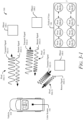
- FIG. 1 illustrates an example environment 100 in which the described FMCW lidar system 102 can be implemented.
- the FMCW lidar system 102 (referred to simply as “lidar system 102") transmits laser light and resolves return signals among pixels.
- the lidar system 102 is mounted to, or integrated within, a vehicle 104.
- the lidar system 102 is capable of detecting one or more objects 108 that are in proximity to the vehicle 104.
- the vehicle 104 can represent other types of motorized vehicles (e.g ., a motorcycle, a bus, a tractor, a semi-trailer truck, or construction equipment), types of non-motorized vehicles (e.g.
- the vehicle 104 can tow or include a trailer or other attachments.
- vehicle manufacturers can mount the lidar system 102 to any moving platform, including moving machinery or robotic equipment.
- the lidar system 102 is mounted on the roof of the vehicle 104 and provides a field-of-view 106 illuminating the object 108.
- the lidar system 102 divides the field-of-view 106 into pixels (as illustrated in FIG. 3-1 ).
- the lidar system 102 can project the field-of-view 106 from any exterior surface of the vehicle 104.
- vehicle manufacturers can integrate the lidar system 102 into a bumper, side mirror, or any other interior or exterior location where distance and radial velocity of the object 108 require detection.
- the vehicle 104 includes multiple lidar systems 102, such as a first lidar system 102 and a second lidar system 102 that together provide a larger field-of-view 106.
- vehicle manufacturers can design the locations of the one or more lidar systems 102 to provide a particular field-of-view 106 that encompasses a region of interest in which the object 108 may be present.
- Example field-of-views 106 include a 360-degree field-of-view, one or more 180-degree fields of view, one or more 90-degree fields of view, and so forth, which can overlap or be combined into a field-of-view 106 of a particular size.
- the object 108 is composed of one or more materials that reflect lidar signals. Depending on the application, the object 108 can represent a target of interest. In some cases, the object 108 is a moving object 110, such as another vehicle 110-1, a semi-trailer truck 110-2, a human 110-3, an animal 110-4, a bicycle 110-5, or a motorcycle 110-6. In other cases, the object 108 represents a stationary object 112, such as a traffic cone 112-1, a concrete barrier 112-2, a guard rail 112-3, a fence 112-4, a tree 112-5, or a parked vehicle 112-6.
- the stationary object 112 can be continuous ( e.g. , the concrete barrier 112-2, the guard rail 112-3) or discontinuous ( e.g. , the traffic cone 112-1) along a portion of the road.
- the lidar system 102 is different than some FMCW lidar systems because it uses a different waveform for consecutive pixels to resolve return signals among pixels instead of incorporating a transmission delay between transmit signals for different pixels.
- the different waveforms can be formed using different amplitude modulations for consecutive pixels, for example.
- the lidar system 102 uses the waveforms to generate template signals in the frequency domain and compares a return signal to the template signals. From the comparison of the return signal to the template signals, the lidar system 102 identifies the pixel that corresponds to the return signal and a characteristic of the object 108 that reflected the return signal.
- Example characteristics include range and range-rate information or angular information for the object 108.
- the lidar system 102 can output one or more of these characteristics for automotive applications (e.g ., autonomous-driving systems, driver-assistance systems). By using different waveforms for consecutive pixels, the lidar system 102 can scan more frames in less time than other lidar systems that must extend the total time for each pixel to isolate return signals. The lidar system 102 can also process and detect return signals for multiple pixels within a single detection window to further increase its throughput.
- automotive applications e.g ., autonomous-driving systems, driver-assistance systems.
- FIG. 2 illustrates the lidar system 102 as part of the vehicle 104.
- the vehicle 104 also includes vehicle-based systems 202 that rely on data from the lidar system 102, such as a driver-assistance system 204 and an autonomous-driving system 206.
- vehicle-based systems 202 use lidar data provided by the lidar system 102 to perform a function.
- the driver-assistance system 204 provides blind-spot monitoring and generates an alert that indicates a potential collision with an object 108 that is detected by the lidar system 102.
- the lidar data from the lidar system 102 indicates when it is safe or unsafe to change lanes.
- the driver-assistance system 204 suppresses alerts responsive to the lidar system 102, indicating that the object 108 represents a stationary object 112, such as a road barrier.
- the driver-assistance system 204 can avoid annoying the driver with alerts while the vehicle 104 is driving next to the road barrier. Suppressing alerts can also be beneficial in situations in which reflections from the road barrier generate false detections that appear to be moving objects. By suppressing the alerts, these false detections will not cause the driver-assistance system 204 to alert the driver.
- the autonomous-driving system 206 may move the vehicle 104 to a particular location on the road while avoiding collisions with objects 108 detected by the lidar system 102.
- the lidar data provided by the lidar system 102 can provide information about distance and radial velocity of the objects 108 to enable the autonomous-driving system 206 to perform emergency braking, perform a lane change, or adjust the speed of the vehicle 104.
- the lidar system 102 includes a communication interface 208 to transmit the lidar data to the vehicle-based systems 202 or another component of the vehicle 104.
- the communication interface 208 can transmit the data over a communication bus of the vehicle 104, for example, when the individual components of the lidar system 102 are integrated within the vehicle 104.
- the lidar data provided by the communication interface 208 is in a format usable by the vehicle-based systems 202.
- the communication interface 208 may provide information to the lidar system 102, such as the speed of the vehicle 104 or whether a turn blinker is on or off. The lidar system 102 can use this information to configure itself appropriately.
- the lidar system 102 can determine an absolute speed of the object 108 by compensating for the speed of the vehicle 104.
- the lidar system 102 can dynamically adjust the field-of-view 106 based on whether a right-turn blinker or a left-turn blinker is on.
- the lidar system 102 also includes beam-steering components 210 and a transceiver 212.
- the beam-steering components 210 can include mechanical and/or electromechanical components to shape or steer lidar laser signals and for detecting lidar reflections. Using the beam-steering components 210, the lidar system 102 can steer and shape lidar signals through various optical beamforming techniques.
- the lidar system 102 can include mechanical beam-steering components.
- the beam-steering components 210 include high-grade optics and a rotating assembly to create a wide ( e.g ., three-hundred-sixty degree) field-of-view 106.
- the lidar system 102 can be a solid-state lidar system, such as a microelectromechanical-system (MEMS)-based lidar system, a flash-based lidar system, or an optical phased-array lidar system.
- MEMS microelectromechanical-system
- the beam-steering components 210 do not include a rotating mechanical component and may, therefore, be less expensive than a mechanical-scanning lidar system.
- the lidar system 102 can include multiple solid-state lidar modules, with each module positioned at a different location on the vehicle 104.
- the modules may be on the front, rear, or sides of the vehicle 104 and, when combined, create a single point cloud.
- the lidar system 102 has a field-of-view 106 that is similar to the field-of-view 106 of a mechanical-scanning lidar system.
- the transceiver 212 includes components, circuitry, and logic for emitting lidar signals via the beam-steering components 210 and receiving reflected lidar signals via the beam-steering components 210.
- the transceiver 212 can include a transmitter and a receiver integrated together into a single package or it can include the transmitter and receiver as separate components. The transceiver 212 and its operation is further described with respect to FIG. 4 .
- the lidar system 102 also includes one or more processors 214 and computer-readable storage media (CRM) 216.
- the CRM 216 includes a signal-matching module 218 and a detection processing module 220.
- the signal-matching module 218 and the detection processing module 220 can be implemented using hardware, software, firmware, or a combination thereof.
- the processor 214 executes instructions for implementing the signal-matching module 218 and the detection processing module 220. Together, the signal-matching module 218 and the detection processing module 220 enable the processor 214 to control the transmission of lidar signals, process responses from the beam-steering components 210, and generate lidar data for the vehicle-based systems 202.
- the signal-matching module 218 processes return signals provided by the transceiver 212 into data that is usable by the detection processing module 220.
- the signal-matching module 218 also analyzes the return signals to resolve detections by the lidar system 102 and map the return signals to their corresponding pixels within the field-of-view 106.
- the signal-matching module 218 can also provide feedback to the transceiver 212 to configure the transmission of lidar signals.
- the signal-matching module 218 can provide feedback data to the transceiver 212 to control the modulation (e.g ., shape, frequency, amplitude, phase) of the transmit signals.
- the detection processing module 220 analyzes the data output by the signal-matching module 218 and produces lidar data for the vehicle-based systems 202.
- Example types of lidar data include a Boolean value that indicates whether a detection from the object 108 is present within a particular region of interest, a number that represents a characteristic of the object 108 ( e.g. , range, range-rate, radial velocity, angular information), or a value that indicates the type of object 108 ( e.g. , a moving object 110, a stationary object 112, a living object, a non-living object).
- FIG. 3-1 illustrates an example operation of the lidar system 102 that resolves return signals among pixels.
- the lidar system 102 includes the field-of-view 106, which shows the pixels 306-11, 306-21, 306-31, ..., 306-X1, ..., 306-XY, 306-3Y, 306-2Y, 306-1Y, and all other pixels scanned during a frame.
- the pixels 306 are shown arranged in an X -pixel-wide-by- Y -pixel-high grid and are scanned individually in the order indicated by the arrows, one row (or column) at a time.
- objects 108-1, 108-2, and 108-3 are located at a particular range and angle from the lidar system 102.
- the lidar system 102 transmits a transmit signal 302.
- the lidar system 102 emits a transmit signal 302-11, which is a portion of the transmit signal 302, in the pixel 306-11.
- the transmit signal 302-11 has a first amplitude modulation.
- the lidar system 102 emits the transmit signals 302-21 and 302-31 in the pixels 306-21 and 306-31, respectively.
- the transmit signals 302-11 to 302-31 are collectively the transmit signal 302.
- the transmit signals 302-21 and 302-31 have a second amplitude modulation and a third amplitude modulation, respectively.
- the second amplitude modulation is different than both the first amplitude modulation (applied to the transmit signal 302-11) and the third amplitude modulation (applied to the transmit signal 302-21).
- the third amplitude modulation can be the same or different than the first amplitude modulation. In other words, the first amplitude modulation can be reused for another pixel within a frame, but the amplitude modulations used for consecutive pixels are different.
- the amplitude modulation applied to the transmit signals 302 provide a different waveform for consecutive pixels to assist in resolving return signals among pixels.
- the lidar system 102 can apply different types of waveforms to consecutive pixels by, for example, varying the phase modulation, frequency modulation, amplitude modulation, or any combination thereof.
- Each transmit signal 302 can include one or more chirps.
- a chirp is a portion of the transmit signal 302 in which the frequency increases (up-chirp), decreases (down-chirp), or remains constant (flat-chirp) over time.
- the lidar system 102 employs a single up-chirp for each transmit signal 302 within a single pixel 306, with the frequency of each chirp linearly increasing over time.
- the lidar system 102 can apply a triangle-slope cycle with two chirps for each transmit signal 302 within a pixel 306, in which the frequency of each chirp alternates between linearly increasing and linearly decreasing over time.
- the lidar system 102 can tailor the number of chirps for each of the transmit signals 302 and the transmission characteristics of the chirps (e.g ., bandwidth, center frequency, duration, transmit power) to achieve a particular detection range, range resolution, or Doppler resolution.
- the transmission characteristics of the chirps e.g ., bandwidth, center frequency, duration, transmit power
- the beam-steering components 210 steer each transmit signal 302 so that the lidar system 102 sequentially scans the pixels 306 within the field-of-view 106.
- the lidar system 102 transmits the transmit signals 302-11 to 302-31 in a continuous sequence and not as a series of discrete signals.
- a frame (not shown) represents the time it takes to scan all the individual pixels 306 within the field-of-view 106.
- At least a part of the transmit signal 302-11 is reflected by the object 108-1.
- the reflected portion represents a return signal 304-11.
- the lidar system 102 receives the return signal 304-11 and processes the return signal 304-11 to extract lidar data regarding the object 108-1 for the vehicle-based systems 202.
- the amplitude of the return signal 304-11 is smaller than the amplitude of the transmit signal 302-11 due to losses incurred during propagation and reflection.
- the lidar system 102 receives the return signals 304-21 and 304-31 and processes the return signals 304-21 and 304-31 to extract lidar data regarding the objects 108-2 and 108-3 for the vehicle-based systems 202.
- the return signals 304-11 to 304-31 are collectively the return signal 304.
- the return signals 304-11 to 304-31 represent a delayed version of the transmit signals 302-11 to 302-31, respectively.
- the amount of delay is proportional to the range ( e.g ., distance) from the objects 108-1 to 108-3 to the lidar system 102. For example, this delay represents the time it takes the transmit signal 302-11 to propagate from the lidar system 102 to the object 108-1 and for the return signal 304-11 to travel back to the lidar system 102.
- the return signals 304 are shifted in frequency relative to the transmit signal 302 due to the Doppler effect. This shift in the frequency of the return signals 304 is known as the Doppler frequency.
- characteristics of the return signals 304 are dependent upon motion of the objects 108, respectively, or motion of the vehicle 104. Similar to the transmit signals 302, the return signals 304 are composed of one or more chirps. This document further describes the characteristics of the transmit signals 302 and the return signals 304 with respect to FIG. 3-2 .
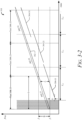
- FIG. 3-2 illustrates a frequency-time plot 310 of the transmit signal 302 and the return signal 304 for the pixels 306 of the lidar system 102 of FIG. 3-1 .
- the vertical axis represents frequency and the horizontal axis represents time.
- the frequency-time plot 310 illustrates the transmit signal 302 and the return signal 304 for a single frame.
- the frequency-time plot 310 depicts multiple pixels 306 and multiple detection windows Ti.
- each detection window Ti is associated with a particular pixel 306.
- the detection windows T i11 , T i21 , and T i31 are associated with the pixels 306-11, 306-21, and 306-31, respectively.
- the detection window T i11 occurs during a time that a portion of the transmit signal 302-11 is transmitted and a portion of the transmit signal 302-12 is transmitted.
- the duration for each detection window T i is sufficient to enable the lidar system 102 to receive reflections for a particular detection range.
- the transceiver 212 collects samples of the return signal 304. As described above with respect to FIG. 3-1 , these return signals 304 represent reflections of the transmit signal 302 for the associated pixel 306 or reflections of the transmit signal 302 associated with a neighboring pixel 306.
- the lidar system 102 receives the return signal 304-11 during a detection window T i11 , obtaining characteristics (e.g. , range information, range-rate information, angular information) of the object 108-1 for the pixel 306-11.
- the lidar system 102 subsequently receives the return signal 304-21 and the return signal 304-31, obtaining characteristics of the object 108-2 and the object 108-3 for the pixel 306-21 and the pixel 306-31, respectively.
- the lidar system 102 can determine angular information of the object 108 (e.g., the object 108-2) based on the angle associated with the corresponding pixel 306 (e.g., the pixel 306-2).
- the lidar system 102 determines a beat frequency ( f b ) for the return signals 304.
- the lidar system 102 can use the beat frequency to obtain range and/or range-rate information for the pixels 306, as presented in the following equations.
- R is range ( e.g. , distance) to the object 108
- v range-rate (e.g., radial velocity) of the object 108
- c is the speed of light
- f c is the frequency of the transmit signal 302 (e.g., the carrier frequency)
- T is the period of the pixel 306, and B is the bandwidth of the pixel 306.
- the lidar system 102 processes the return signal 304 to determine the beat frequency. For example, the return signal 304-11 is received during the detection window T i11 . The process repeats for each of the pixels 306 in the field-of-view 106. In this example, the return signal 304-11 is received during the detection window T i11 , which corresponds to the pixel 306-11, and the beginning portion of the detection window T i21 , which corresponds to the pixel 306-21. During the latter portion of the detection window T i21 and the beginning portion of the detection window T i31 , the lidar system 102 receives both the return signal 304-21 and the return signal 304-31. The return signals 304-21 and 304-31 can overlap because the object 108-2, which reflected the return signal 304-21, is farther away from the lidar system 102 than the object 108-3, which reflected the return signal 304-31.
- the linearly-increasing frequency of the transmit signal 302 (as shown in FIG. 3-2 ) allows the beat frequency of the return signals 304 to be correctly determined via the mixing operation in the receiver 404, which is discussed with respect to FIG. 4 .
- the detection window T i may include return signals 304 from a single pixel ( e.g. , the pixel 306-21) or consecutive pixels ( e.g. , the pixels 306-21 and 306-31).
- a single detection window T i can span a portion of time in which a current transmit signal 302 is transmitted and a portion of a subsequent transmit signal 302 is transmitted.
- the detection windows T i can be lengthened to listen for return signals 304 for larger groups of consecutive pixels.
- the detection window T i11 can be lengthened to listen for return signals 304 for the pixels 306-11 to 306-31.
- the single detection window T i can span a portion of time that the current transmit signal 302 is transmitted and a portion of time that two or more subsequent transmit signals 302 are transmitted.
- the signal-matching module 218 (of FIG. 2 ) can match each return signal 304 to its corresponding pixel 306, as further described with respect to FIG. 4 .
- FIG. 4 illustrates an example transceiver 212 and an example processor 214 of the described lidar system 102.
- the transceiver 212 is coupled between the beam-steering components 210 (of FIG. 2 ) and the processor 214.
- the processor 214 implements the signal-matching module 218 and the detection processing module 220.
- the processor 214 is connected to a data path of the return signal 304.
- the transceiver 212 includes at least one transmitter 402 and at least one receiver 404.
- the transmitter 402 generates the transmit signal 302 and passes the transmit signal 302 to the beam-steering components 210.
- the transmitter 402 includes at least one amplitude modulator 406, at least one frequency modulator 408, and at least one emitter 410.
- the emitter 410 includes a laser or similar component, which generates an optical signal.
- the emitter 410 is coupled to the frequency modulator 408.
- the frequency modulator 408 performs frequency modulation to enable the lidar system 102 to operate as a FMCW lidar system. In some cases, the frequency modulator 408 varies the frequency modulation for transmit signals 302 that are associated with different pixels 306.
- the frequency modulator 408 causes the frequency across the set of transmit signals 302-11 to 302-31 to linearly increase over time. In other words, the frequency modulator 408 causes the transmit signal 302-31 to have a higher center frequency than a center frequency of the transmit signal 302-21 and causes the center frequency of the transmit signal 302-21 to be higher than a center frequency of the transmit signal 302-11.
- the frequency modulator 408 also causes the frequencies of the individual transmit signals 302-11, 302-21, and 302-31 to increase at the same rate (e.g., the same frequency-time slope). If the transmit signal 302 includes multiple chirps, the frequency modulator 408 can also vary the frequency modulation for different chirps that are associated with the same pixel 306.
- the amplitude modulator 406 is coupled to the frequency modulator 408 and applies a unique amplitude modulation scheme to enable detections to be resolved for different return signals 304 among the pixels 306.
- the amplitude modulator 406 can vary the amplitude modulation for transmit signals 302 that are associated with different pixels 306. If the transmit signal 302 includes multiple chirps, the amplitude modulator 406 can also vary the amplitude modulation for different chirps that are associated with the same pixel 306. In other implementations, the amplitude modulator 406 can be implemented as another type of modulator 406 that provides amplitude modulation, frequency modulation, phase modulation, or any combination thereof to generate unique waveforms for consecutive pixels 306.
- the receiver 404 receives and conditions a composite return signal 418 for the processor 214.
- the composite return signal 418 includes at least one of the return signals 304 of FIGs. 3-1 and 3-2 .
- the receiver 404 can include a photo-detector and other receiver elements, such as an amplifier, a mixer, a filter, and an analog-to-digital converter.
- the emitter 410 generates a laser signal 420, which can have a steady (e.g ., constant) frequency.
- the frequency modulator 408 modulates the frequency of the laser signal 420 to generate a frequency-modulated (FM) laser signal 422.
- the amplitude modulator 406 modulates the amplitude of the frequency-modulated laser signal 422 to generate the transmit signal 302, which has a particular amplitude modulation that is associated with its corresponding pixel 306.
- the transmit signal 302 propagates through space and is reflected by the object 108 ( e.g. , one of the objects 108-1 to 108-3 depicted in FIG. 3-1 ).
- the receiver 404 receives the reflected version of the transmit signal 302, which is represented by the composite return signal 418.
- the receiver 404 mixes the composite return signal 418 with the FM laser signal 422 to downconvert and demodulate the frequency of the composite return signal 418.
- the receiver 404 generates a sampled return signal 424, which is a time-domain digital signal.
- the processor 214 accepts the sampled return signal 424 and analyzes the sampled return signal 424 to generate lidar data 428.
- the processor 214 executes the signal-matching module 218 and the detection processing module 220.
- the signal-matching module 218 performs one or more operations to associate the return signal 304 to its corresponding pixel 306.
- the signal-matching module 218 passes detection data 426 to the detection processing module 220.
- the detection data 426 can include each of the sampled return signals 424 and an indication of its corresponding pixel 306.
- the detection processing module 220 analyzes the detection data 426 and generates the lidar data 428.
- the lidar data 428 can include range and/or range-rate information or angular information of the object 108 that reflected the return signal 304. In other cases, the lidar data 428 indicates whether an object 108 is in a blind spot of the vehicle 104.
- the processor 214 provides the lidar data 428 to the vehicle-based systems 202 (of FIG. 2
- the processor 214 outputs a modulation control signal 430 to the amplitude modulator 406 or the frequency modulator 408.
- the processor 214 directs the amplitude modulator 406 or the frequency modulator 408 to apply a particular modulation to the transmit signal 302 associated with a subsequent pixel 306.
- the modulation control signal 430 can be output by different components, including, for example, the signal-matching module 218, the detection processing module 220, or the receiver 404.
- the modulation applied by the amplitude modulator 406 and the frequency modulator 408 can be programmed to cycle through different modulations without receiving the modulation control signal 430.
- the signal-matching module 218 can resolve return signals among different pixels 306, as further described with respect to FIG. 5-1 .
- FIG. 5-1 illustrates an example signal-matching module 218 of the described lidar system 102.
- the signal-matching module 218 includes a transform module 502, a template signal module 504, a comparison module 506, and a signal resolution module 508.
- the lidar system 102 receives the return signal 304-11 during the detection window T i11 , which corresponds to the pixel 306-11.
- the transform module 502 accepts the sampled return signal 424-11 associated with the return 304-11 and generates a transformed return signal 512-11.
- the transform module 502 transforms the sampled return signal 424 associated with the return signal 304 into the frequency domain.
- the transform module 502 performs a Fourier transform, such as a fast Fourier transform, of the composite return signal 418.
- the transform module 502 performs a Fourier transform on the sampled return signal 424-11 to generate a transformed return signal 512-11.
- the transformed return signal 512-11 provides the frequencies and amplitudes of the sampled return signal 424-11.
- the transformed return signal 512 is provided as an input to the comparison module 506.
- the template signal module 504 generates template signals 510 in the frequency domain.
- the template signals 510 have the same side bands as the transmit signal 302 of the pixel(s) corresponding to the current detection window T i ( e.g., the pixel 306-11), the subsequent pixel ( e.g. , pixel 306-21), and/or the previous pixel (not explicitly shown in FIG. 3-2 ).
- the template signal module 504 generates template signals 510-11 and 510-21 in the frequency domain.
- the template signal 510-11 has the same side bands as the transmit signal 302-11, and the template signal 510-21 has the same side bands as the transmit signal 302-21. In this case, the amplitude modulation determines frequency offset of the side bands in the template signals 510.
- the template signal module 504 outputs the template signals 510 to the comparison module 506.
- the comparison module 506 compares the transformed return signal 512 to the template signals 510 to generate comparison results 514.
- the comparison module 506 can utilize a cross-correlation, convolution, or match-filtering method to compare the transformed return signal 512 to the template signals 510 in the frequency domain. In the depicted example, the comparison module 506 compares the transformed return signal 512-11 to the template signals 510-11 and 510-21 to generate the comparison results 514-11 and 514-21.
- the comparison module 506 outputs the comparison results 514 to the signal resolution module 508.
- the signal resolution module 508 determines to which of the pixels 306 the return signal 304 corresponds. For example, the signal resolution module 508 compares a maximum peak of the comparison result 514-11 to a maximum peak of the comparison result 514-21 and identifies the largest peak among the comparison results 514. In the depicted example, the comparison result 514-11 has the largest peak. Accordingly, the signal resolution module 508 associates the return signal 304-11 to the pixel 306-11.
- the signal resolution module 508 can also identify the frequency of the largest peak, which represents the beat frequency of the return signal 304-11. As described with respect to FIG. 3-2 , the lidar system 102 can then compute the range information, range-rate information, and/or angular information associated with object 108-1 based on the beat frequency of the return signal 304-11.
- the signal resolution module 508 can confirm that the return signal 304-11 corresponds to the pixel 306-11 by evaluating sidebands in the comparison result 514-11.
- the signal resolution module 508 compares the offset between the largest peak and the sideband peaks in the comparison result 514-11 to the sideband offset in the template signal 510-11.
- the sideband peaks occur in the comparison result 514-11 at the same offset as they occur in the template signal 510-11.
- the signal resolution module 508 performs additional operations to resolve ambiguities in associating the return signals 304 to their corresponding pixels 306, as further described with respect to FIG. 5-2 .
- FIG. 5-2 illustrates another example implementation of the signal-matching module 218 with feedback.
- the signal resolution module 508 provides a feedback signal 530 to the transform module 502 and a feedback signal 532 to the template signal module 504.
- the feedback is provided to resolve ambiguities in associating the return signals 304 to their corresponding pixels 306. These ambiguities can occur if the beat frequencies of two returns signals 304 are approximately the same and the sideband peaks of the return signals are near each other. As a result, it can be difficult to confirm which return signal 304 corresponds to which pixel 306 because of the peak amplitudes in the comparison results 514 being similar for the different return signals 304.
- the transform module 502 accepts sampled return signals 424-21 and 424-31, which were received by the transceiver 212 as the composite return signal 418 during the detection window T i31 and correspond to the return signals 304-21 and 304-31, as shown in FIG. 3-2 .
- the transform module 502 generates, using a Fourier transform, transformed return signals 512-21 and 512-31 (not shown in FIG. 5-2 ) in the frequency domain.
- the template signal module 504 generates template signals 510-21 and 510-31 in the frequency domain.
- the comparison module 506 compares the transformed return signals 512-21 and 512-31 to the template signals 510-21 and 510-31 to generate comparison results 514 (not shown).
- the signal resolution module 508 then associates, based on the largest peak in the comparison results 514, the return signal 304-21 to the template signal 510-21 and the return signal 304-31 to the template signal 510-31.
- the beat frequency associated with the return signals 304-21 and 304-31 are substantially equal and their associated beat frequencies are near each other, which can occur when the objects 108 that reflected the returns signals 304 are a similar distance away from the lidar system 102.
- the signal resolution module 508 can determine that the composite return signal 418 contains multiple return signals 304 (e.g., the return signal 304-21 and 304-31) by, for example, determining that there are multiple peak amplitudes in the comparison results 514 that are above a threshold value. These multiple return signals 304 can be associated with the same pixel 306 or different pixels 306. The signal resolution module 508 can also determine the presence of multiple return signals 304 by identifying multiple pairs of sideband peaks, which indicates that a specific beat frequency exists for each pair of sideband peaks.
- the signal resolution module 508 can confirm that the return signal 304-21 corresponds to the pixel 306-21 and that the return signal 304-31 corresponds to the pixel 306-31 by performing the comparison process again with the beat frequency filtered out. Filtering out the beat frequency results in only the sideband peaks-not the beat frequencies-contributing to the comparison results generated by the comparison module 506.
- the signal resolution module 508 provides the feedback signal 530 to the transform module 502 and the feedback signal 532 to the template signal module 504. Responsive to accepting the feedback signal 530, the transform module 502 generates a filtered transformed return signal 522 by filtering out the beat frequencies of the return signals 304-21 and 304-31 within the composite return signal 418.
- the filtered transformed return signals 522-21 and 522-31 share approximately the same beat frequency, which is represented by the double-set of dashed lines in the center of the pairs of the sideband peaks.
- the side bands of the filtered transformed return signal 522-21 are represented as solid black in FIG. 5-2 and the side bands of the filtered transformed return signal 522-31 are represented by the white-speckled pattern.
- the template signal module 504 generates filtered template signals 520-21 and 520-31 by filtering out the beat frequency of the transmit signals 302-21 and 302-31.
- the center frequency of the filtered template signals 520 are represented as a dashed line to indicate that these frequencies have been filtered out.
- the comparison module 506 compares the filtered transformed return signal 522, which includes the filtered transformed return signals 522-21 and 522-31, with the filtered template signals 520-21 and 520-31 to generate filtered comparison results 524-21 and 524-31.
- the filtered comparison result 524-21 is the output of comparing the filtered transformed return signal 522-21 with the filtered template signal 520-21 in the frequency domain.
- the filtered comparison result 524-31 is the output of comparing the filtered transformed return signal 522 with the filtered template signal 520-31 in the frequency domain.
- the filtered comparison results 524 corresponding to the return signal 304-21 are represented by solid-black triangles and the filtered comparison results 524 corresponding to the return signal 304-31 are represented by the white-speckled triangles.
- the signal resolution module 508 then associates, based on the largest peak for each pair of side bands in the filtered comparison results 524, the return signal 304-21 to the filtered template signal 520-21 and the return signal 304-31 to the filtered template signal 520-31.
- the pair of side band peaks with the largest amplitude in the filtered comparison result 524-21 are offset from each other by a similar amount as the side bands in the filtered template signal 520-21, which is associated with the transmit signal 302-21, the return signal 304-21, and the pixel 306-21.
- the pair of side band peaks with the largest amplitude in the filtered comparison result 524-31 are offset from each other by a similar amount as the side bands in the filtered template signal 520-31, which is associated with the transmit signal 302-31, the return signal 304-31, and the pixel 306-31.
- the lidar system 102 can then compute the range and range-rate information or the angular information associated with the objects 108 based on the beat frequencies of the return signals 304-21 and 304-31.
- the beat frequency associated with the return signal 304-21 can overlap with a side band of the return signal 304-31.
- the signal resolution module 508 can similarly confirm that the return signal 304-21 corresponds to the pixel 306-21 and that the return signal 304-31 corresponds to the pixel 306-31 by performing the comparison process again with the beat frequency filtered out.
- FIG. 6 depicts an example method 600 performed by a FMCW lidar system that resolves return signals among pixels.
- Method 600 is shown as sets of operations (or acts) performed, but not necessarily limited to the order or combinations in which the operations are shown herein. Further, any of one or more of the operations may be repeated, combined, or reorganized to provide other methods.
- a first signal is transmitted for an initial pixel of two consecutive pixels.
- the first signal has a first amplitude modulation.
- the transmitter 402 of the lidar system 102 on the vehicle 104 transmits, for the pixel 306-11 of the consecutive pixels 306-11 and 306-21, the transmit signal 302-11, as shown in FIG. 3-1 .
- the transmit signal 302-11 has a first amplitude modulation.
- a second signal is transmitted for a subsequent pixel of the two consecutive pixels.
- the second signal has a second amplitude modulation, which is different than the first amplitude modulation.
- the transmitter 402 of the lidar system 102 transmits, for the pixel 306-21, the transmit signal 302-21, as shown in FIG. 3-1 .
- the transmit signal 302-21 has a second amplitude modulation, which is different than the first amplitude modulation.
- the first signal e.g. , the transmit signal 302-11) and the second signal (e.g. , the transmit signal 302-21) are emitted in a continuous sequence ( e.g ., are part of the same transmit signal) and are not discrete signals.
- a return signal is received during a detection window. At least a portion of the first signal and the second signal is transmitted during the detection window.
- the receiver 404 of the lidar system 102 receives, during the detection window T i11 corresponding to the pixel 306-11, the return signal 304-11, as shown in FIG. 3-2 .
- a portion of the transmit signal 302-11 and the transmit signal 302-21 is transmitted during the detection window T i11 .
- the detection window T i11 can correspond to two or more pixels ( e.g. , the pixels 306-11 and 306-21).
- a first comparison result and a second comparison result are generated, by comparing the return signal to a first template signal and a second template signal in a frequency domain, respectively.
- the first template signal has the first amplitude modulation and the second template signal has the second amplitude modulation.
- the signal-matching module 218 of the lidar system 102 generates the template signal 510-11 and the template signal 510-21, as shown in FIG. 5-1 .
- the template signal 510-11 has the first amplitude modulation, which was applied to the transmit signal 302-11 and is associated with the pixel 306-11.
- the template signal 510-21 has the second amplitude modulation, which was applied to the transmit signal 302-21 and is associated with the pixel 306-21.
- the signal-matching module 218 generates, by comparing in the frequency domain the return signal 304-11 with the template signal 510-11 and the template signal 510-21, the comparison result 514-11 and the comparison result 514-21.
- the comparison result 514-11 is associated with the template signal 510-11 and the pixel 306-11.
- the comparison result 514-21 is associated with the template signal 510-21 and the pixel 306-21.
- a respective pixel of the two consecutive pixels that corresponds to the return signal is determined, based on the first comparison result and the second comparison result. For example, the signal-matching module 218 of the lidar system 102 determines that, among the comparison results 514, the comparison result 514-11 has the largest peak value. The signal-matching module 218, therefore, determines that the pixel 306-11 corresponds to the return signal 304-11, as shown in FIG. 5-1 .
- a characteristic of an object that reflected the return signal is identified, based on the return signal and a transmitted signal of the respective pixel corresponding to the return signal.
- the detection processing module 220 identifies, based on the return signal 304-11 and the transmit signal 302-11 of the pixel 306-11, a characteristic of the object 108-1 (e.g. , range information, range-rate information, angular information) that reflected the return signal 304-11, as shown in FIG. 3-2 .
Landscapes
- Physics & Mathematics (AREA)
- Engineering & Computer Science (AREA)
- Electromagnetism (AREA)
- Computer Networks & Wireless Communication (AREA)
- General Physics & Mathematics (AREA)
- Radar, Positioning & Navigation (AREA)
- Remote Sensing (AREA)
- Optical Radar Systems And Details Thereof (AREA)
- Traffic Control Systems (AREA)
- Radar Systems Or Details Thereof (AREA)
Claims (14)
- Verfahren, das von einem Lidar-System (102) durchgeführt wird, umfassend:Senden (602), für ein anfängliches Pixel von zwei aufeinanderfolgenden Pixeln (306-11, 306-21), eines ersten Sendesignals (302-11), wobei das erste Sendesignal (302-11) eine erste Amplitudenmodulation aufweist;Senden (604), für ein nachfolgendes Pixel (306-21) der zwei aufeinanderfolgenden Pixel (306-11, 306-21), eines zweiten Sendesignals (302-21), wobei das zweite Sendesignal (302-21) eine zweite Amplitudenmodulation aufweist, wobei sich die zweite Amplitudenmodulation von der ersten Amplitudenmodulation unterscheidet;Empfangen (606), während eines Detektionsfensters (Ti11) und in dem mindestens ein Teil des ersten Sendesignals (302-11) und des zweiten Sendesignals (302-21) gesendet werden, eines Rücksignals (304-11);gekennzeichnet durchErzeugen (608), durch Vergleichen des Rücksignals (304-11) in einem Frequenzbereich mit einem ersten Vorlagensignal (510-11) und einem zweiten Vorlagensignal (510-21), jeweils eines ersten Vergleichsergebnisses (514-11) und eines zweiten Vergleichsergebnisses (514-21), wobei das erste Vorlagensignal (510-11) die erste Amplitudenmodulation aufweist, wobei das zweite Vorlagensignal (510-21) die zweite Amplitudenmodulation aufweist;Bestimmen (610), basierend auf dem ersten Vergleichsergebnis (514-11) und dem zweiten Vergleichsergebnis (514-21), eines jeweiligen Pixels der zwei aufeinanderfolgenden Pixel (306-11, 306-21), das dem Rücksignal (304-11) entspricht; undIdentifizieren (612), basierend auf dem Rücksignal (304-11), einer Eigenschaft eines Objekts (108-1), das das Rücksignal (304-11) reflektiert hat, wobei sich das Objekt (108-1) innerhalb eines Bereichs befindet, der dem jeweiligen Pixel zugeordnet ist,wobei das Bestimmen des jeweiligen Pixels der zwei aufeinanderfolgenden Pixel (306-11, 306-21), das dem Rücksignal (304-11) entspricht, umfasst:Bestimmen, aus dem ersten Vergleichsergebnis (514-11) und dem zweiten Vergleichsergebnis (514-21), eines größten Spitzenwerts und einer Frequenz des größten Spitzenwerts, wobei die Frequenz des größten Spitzenwerts eine Schwebungsfrequenz des Rücksignals (304-11) ist; undIdentifizieren eines Vorlagensignals (510), das verwendet wird, um ein Vergleichsergebnis (514) zu erzeugen, das dem größten Spitzenwert zugeordnet ist, wobei das Vorlagensignal aus dem ersten Vorlagensignal (510-11) und dem zweiten Vorlagensignal (510-21) ist und dem größten Spitzenwert und dem Vergleichsergebnis (514) aus dem ersten Vergleichsergebnis (514-11) und dem zweiten Vergleichsergebnis (514-21) zugeordnet ist.
- Verfahren nach Anspruch 1, ferner umfassend:Empfangen, während des Detektionsfensters (Ti11), eines zweiten Rücksignals (304-21), wobei das Rücksignal (304-21) und das erste Rücksignal (304-11) ein zusammengesetztes Rücksignal (418) bilden;wobei das Erzeugen des ersten Vergleichsergebnisses (514-11) und des zweiten Vergleichsergebnisses (514-21) das Erzeugen, durch Vergleichen in dem Frequenzbereich des zusammengesetzten Rücksignals (418) mit dem ersten Vorlagensignal (510-11) und dem zweiten Vorlagensignal (510-21), jeweils eines ersten Vergleichsergebnisses (514-11) und eines zweiten Vergleichsergebnisses (514-21) umfasst;wobei das Bestimmen des jeweiligen Pixels der zwei aufeinanderfolgenden Pixel (306-11, 306-21), das dem Rücksignal (304-11) entspricht, das Bestimmen, basierend auf dem ersten Vergleichsergebnis (514-11) und dem zweiten Vergleichsergebnis (514-21), des jeweiligen Pixels (306-11) der zwei aufeinanderfolgenden Pixel (306-11, 306-21), das dem Rücksignal (304-11) entspricht, und eines zweiten jeweiligen Pixels (306-21) der zwei aufeinanderfolgenden Pixel (306-11, 306-21), das dem zweiten Rücksignal (304-21) entspricht, umfasst; undIdentifizieren, basierend auf dem zweiten Rücksignal (304-21), einer Eigenschaft eines zweiten Objekts (108-2), das das zweite Rücksignal (304-21) reflektiert hat, wobei sich das zweite Objekt (108-2) innerhalb eines Bereichs befindet, der dem zweiten jeweiligen Pixel (306-21) zugeordnet ist.
- Verfahren nach Anspruch 2, wobei:das Rücksignal (304-11) eine reflektierte Version des ersten Sendesignals (302-11) ist und das jeweilige Pixel (306-11), das dem Rücksignal (304-11) entspricht, das anfängliche Pixel ist; unddas zweite Rücksignal (304-21) eine reflektierte Version des zweiten Sendesignals (302-21) ist und das zweite jeweilige Pixel (306-21), das dem zweiten Rücksignal (304-21) entspricht, das nachfolgende Pixel ist.
- Verfahren nach einem der Ansprüche 2 oder 3, ferner umfassend:Bestimmen, basierend auf dem Vergleichsergebnis (514-11), das dem jeweiligen Pixel (306-11) des Rücksignals (304-11) entspricht, einer Schwebungsfrequenz des Rücksignals (304-11);Bestimmen, basierend auf dem Vergleichsergebnis (514-21), das dem zweiten jeweiligen Pixel (306-21) des zweiten Rücksignals (304-21) entspricht, einer Schwebungsfrequenz des zweiten Rücksignals (304-21);Bestimmen, dass die Schwebungsfrequenz des Rücksignals (304-11) und die Schwebungsfrequenz des zweiten Rücksignals (304-21) im Wesentlichen gleich sind;Erzeugen eines gefilterten Rücksignals (522), eines ersten gefilterten Vorlagensignals (520-21) und eines zweiten gefilterten Vorlagensignals (520-31) durch Filtern der Schwebungsfrequenzen des Rücksignals (304-11) und des zweiten Rücksignals (304-21), jeweils einer Mittenfrequenz des ersten Vorlagensignals (510-11) und einer Mittenfrequenz des zweiten Vorlagensignals (510-21);Erzeugen, durch Vergleichen in dem Frequenzbereich des gefilterten Rücksignals (522) mit dem ersten gefilterten Vorlagensignal (520-21) und dem zweiten gefilterten Vorlagensignal (520-31), eines ersten gefilterten Vergleichsergebnisses (524-21) und eines zweiten gefilterten Vergleichsergebnisses (524-31); undBestätigen, basierend auf dem ersten gefilterten Vergleichsergebnis (524-21) und dem zweiten gefilterten Vergleichsergebnis (524-31), des jeweiligen Pixels der zwei aufeinanderfolgenden Pixel (306-11, 306-21), das dem ersten gefilterten Rücksignal (522-21) entspricht, und des zweiten jeweiligen Pixels der zwei aufeinanderfolgenden Pixel (306-11, 306-21), das dem zweiten gefilterten Rücksignal (522-31) entspricht.
- Verfahren nach einem der Ansprüche 1 bis 4, wobei das Vergleichen in dem Frequenzbereich des Rücksignals (304-11) mit dem ersten Vorlagensignal (510-11) und dem zweiten Vorlagensignal (510-21) umfasst:Erzeugen des ersten Vorlagensignals (510-11) in einem Frequenzbereich und des zweiten Vorlagensignals (510-21) in dem Frequenzbereich;Erzeugen einer Fourier-Transformation des Rücksignals (304-11); undVergleichen der Fourier-Transformation des Rücksignals (304-11) mit dem ersten Vorlagensignal (510-11) und mit dem zweiten Vorlagensignal (510-21).
- Verfahren nach Anspruch 5, wobei das Vergleichen der Fourier-Transformation des Rücksignals (304-11) mit dem ersten Vorlagensignal (510-11) und mit dem zweiten Vorlagensignal (510-21) das Durchführen einer Kreuzkorrelation, einer Faltung oder eines Optimalfilterverfahrens umfasst.
- Verfahren nach einem der Ansprüche 1 bis 6, wobei:das erste Vorlagensignal (510-11) erste Seitenbänder aufweist, die der ersten Amplitudenmodulation entsprechen;das zweite Vorlagensignal (510-21) zweite Seitenbänder aufweist, die der zweiten Amplitudenmodulation entsprechen; unddas Verfahren ferner das Vergleichen von Frequenzversätzen der Seitenbänder des Vorlagensignals (510), die dem größten Spitzenwert zugeordnet sind, mit den ersten Seitenbändern und den zweiten Seitenbändern umfasst.
- Verfahren nach einem der Ansprüche 1 bis 7, wobei die Eigenschaft des Objekts mindestens eine der folgenden umfasst: einen Abstand von dem Lidar-System (102) zu dem Objekt (108); oder eine radiale Geschwindigkeit des Objekts (108) relativ zu dem Lidar-System (102).
- Verfahren nach Anspruch 8, ferner umfassend das Bestimmen eines Winkels zwischen dem Lidar-System (102) und dem Objekt (108) basierend auf einer Winkelposition des jeweiligen Pixels.
- Verfahren nach einem der Ansprüche 1 bis 9, wobei das erste Sendesignal (302-11) einen oder mehrere erste Chirps umfasst und das zweite Sendesignal (302-21) einen oder mehrere zweite Chirps umfasst.
- Verfahren nach einem der Ansprüche 1 bis 10, ferner umfassend:
Senden, für ein weiteres nachfolgendes Pixel (306-31) von drei aufeinanderfolgenden Pixeln (306-11, 306-21, 306-31), eines dritten Sendesignals (302-31), wobei das dritte Sendesignal (302-31) eine dritte Amplitudenmodulation aufweist, wobei sich die dritte Amplitudenmodulation von sowohl der ersten Amplitudenmodulation als auch der zweiten Amplitudenmodulation unterscheidet, wobei die drei aufeinanderfolgenden Pixel (306-11, 306-21, 306-31) die zwei aufeinanderfolgenden Pixel (306-11, 306-21) beinhalten. - Verfahren nach einem der Ansprüche 1 bis 11, wobei das Lidar-System (102) ein Lidar-System (102) umfasst, das zur Verwendung durch ein Automobil konfiguriert ist.
- Lidar-System (102), umfassend mindestens eine Verarbeitungseinheit, die konfiguriert ist, um das Verfahren nach einem der Ansprüche 1 bis 12 durchzuführen.
- Computerlesbares Speichermedium, umfassend computerausführbare Anweisungen, die, wenn sie ausgeführt werden, einen Prozessor eines Lidar-Systems (102) veranlassen, das Verfahren nach einem der Ansprüche 1 bis 12 durchzuführen.
Priority Applications (1)
| Application Number | Priority Date | Filing Date | Title |
|---|---|---|---|
| EP24193663.2A EP4456344A3 (de) | 2020-07-02 | 2021-06-29 | Auflösung von rücksignalen zwischen pixeln in frequenzmodulierten dauerstrich-lidar-systemen |
Applications Claiming Priority (1)
| Application Number | Priority Date | Filing Date | Title |
|---|---|---|---|
| US16/920,179 US11740338B2 (en) | 2020-07-02 | 2020-07-02 | Resolving return signals among pixels in frequency-modulated continuous-wave (FMCW) lidar systems |
Related Child Applications (2)
| Application Number | Title | Priority Date | Filing Date |
|---|---|---|---|
| EP24193663.2A Division EP4456344A3 (de) | 2020-07-02 | 2021-06-29 | Auflösung von rücksignalen zwischen pixeln in frequenzmodulierten dauerstrich-lidar-systemen |
| EP24193663.2A Division-Into EP4456344A3 (de) | 2020-07-02 | 2021-06-29 | Auflösung von rücksignalen zwischen pixeln in frequenzmodulierten dauerstrich-lidar-systemen |
Publications (2)
| Publication Number | Publication Date |
|---|---|
| EP3933437A1 EP3933437A1 (de) | 2022-01-05 |
| EP3933437B1 true EP3933437B1 (de) | 2024-10-30 |
Family
ID=76730280
Family Applications (2)
| Application Number | Title | Priority Date | Filing Date |
|---|---|---|---|
| EP24193663.2A Withdrawn EP4456344A3 (de) | 2020-07-02 | 2021-06-29 | Auflösung von rücksignalen zwischen pixeln in frequenzmodulierten dauerstrich-lidar-systemen |
| EP21182491.7A Active EP3933437B1 (de) | 2020-07-02 | 2021-06-29 | Auflösung von rückkehrsignalen zwischen pixeln in frequenzmodulierten dauerstrich(fmcw)-lidarsystemen |
Family Applications Before (1)
| Application Number | Title | Priority Date | Filing Date |
|---|---|---|---|
| EP24193663.2A Withdrawn EP4456344A3 (de) | 2020-07-02 | 2021-06-29 | Auflösung von rücksignalen zwischen pixeln in frequenzmodulierten dauerstrich-lidar-systemen |
Country Status (3)
| Country | Link |
|---|---|
| US (2) | US11740338B2 (de) |
| EP (2) | EP4456344A3 (de) |
| CN (1) | CN113885038B (de) |
Families Citing this family (6)
| Publication number | Priority date | Publication date | Assignee | Title |
|---|---|---|---|---|
| EP3822658A1 (de) | 2019-11-15 | 2021-05-19 | Aptiv Technologies Limited | Verfahren und system zur verarbeitung eines von einer laservorrichtung aufgenommenen lasersignals |
| US11480662B2 (en) | 2020-02-12 | 2022-10-25 | Aptiv Technologies Limited | Fast-scanning frequency-modulated continuous wave (FMCW) lidar systems |
| US11971508B2 (en) | 2020-07-08 | 2024-04-30 | Aptiv Technologies AG | Varying waveforms across frames in frequency-modulated continuous-wave (FMCW) lidar systems |
| US12204025B2 (en) * | 2022-08-01 | 2025-01-21 | Imec Vzw | Method and a device for determining a distance to a target |
| US20240036200A1 (en) * | 2022-08-01 | 2024-02-01 | Imec Vzw | Method and a device for determining a distance to a target |
| DE102023110500A1 (de) * | 2023-04-25 | 2024-10-31 | Scantinel Photonics GmbH | Eindeutige Bestimmung von Abstand und Relativgeschwindigkeit von Objekten |
Family Cites Families (21)
| Publication number | Priority date | Publication date | Assignee | Title |
|---|---|---|---|---|
| US4594000A (en) | 1983-04-04 | 1986-06-10 | Ball Corporation | Method and apparatus for optically measuring distance and velocity |
| JP4462060B2 (ja) | 2005-02-14 | 2010-05-12 | 株式会社デンソー | Fmcwレーダ装置 |
| DE102011075767A1 (de) * | 2011-05-12 | 2012-11-15 | Endress + Hauser Gmbh + Co. Kg | Einsatz von aktiven Radarreflektoren in einer produktions- oder fördertechnischen Umgebung der Automatisierungstechnik |
| EP2597484A1 (de) * | 2011-11-24 | 2013-05-29 | Nederlandse Organisatie voor toegepast -natuurwetenschappelijk onderzoek TNO | Aktives FMCW-Radarsystem und Verfahren zum Datentransfer damit |
| US8947644B2 (en) | 2012-01-19 | 2015-02-03 | Raytheon Company | Using multiple waveforms from a coherent LADAR for target acquisition |
| US10247538B2 (en) | 2014-10-29 | 2019-04-02 | Bridger Photonics, Inc. | Accurate chirped synthetic wavelength interferometer |
| US10677924B2 (en) * | 2015-06-23 | 2020-06-09 | Mezmeriz, Inc. | Portable panoramic laser mapping and/or projection system |
| EP3314707A4 (de) * | 2015-06-26 | 2019-02-20 | Mezmeriz, Inc. | Schwebungssignalbandbreitenkomprimierungsverfahren, vorrichtung und anwendungen |
| KR102488038B1 (ko) | 2015-11-19 | 2023-01-13 | 주식회사 에이치엘클레무브 | 차량용 레이더 장치 및 그의 타겟 결정 방법 |
| US11442149B2 (en) | 2016-10-06 | 2022-09-13 | GM Global Technology Operations LLC | LiDAR system |
| EP3548841B1 (de) * | 2016-11-30 | 2025-11-12 | Aurora Operations, Inc. | Verfahren und system zur doppler-detektion und doppler-korrektur der entfernnungsbestimmung mit optischen chirps |
| US10422880B2 (en) * | 2017-02-03 | 2019-09-24 | Blackmore Sensors and Analytics Inc. | Method and system for doppler detection and doppler correction of optical phase-encoded range detection |
| US11119198B2 (en) | 2017-03-28 | 2021-09-14 | Luminar, Llc | Increasing operational safety of a lidar system |
| US10401495B2 (en) * | 2017-07-10 | 2019-09-03 | Blackmore Sensors and Analytics Inc. | Method and system for time separated quadrature detection of doppler effects in optical range measurements |
| US11226403B2 (en) | 2017-07-12 | 2022-01-18 | GM Global Technology Operations LLC | Chip-scale coherent lidar with integrated high power laser diode |
| US11187807B2 (en) | 2017-07-24 | 2021-11-30 | Intel Corporation | Precisely controlled chirped diode laser and coherent lidar system |
| US10613200B2 (en) | 2017-09-19 | 2020-04-07 | Veoneer, Inc. | Scanning lidar system and method |
| US10877154B2 (en) * | 2018-03-27 | 2020-12-29 | Intel Corporation | Range estimation for light detecting and ranging (LIDAR) systems |
| EP3822658A1 (de) | 2019-11-15 | 2021-05-19 | Aptiv Technologies Limited | Verfahren und system zur verarbeitung eines von einer laservorrichtung aufgenommenen lasersignals |
| US11480662B2 (en) | 2020-02-12 | 2022-10-25 | Aptiv Technologies Limited | Fast-scanning frequency-modulated continuous wave (FMCW) lidar systems |
| US11971508B2 (en) | 2020-07-08 | 2024-04-30 | Aptiv Technologies AG | Varying waveforms across frames in frequency-modulated continuous-wave (FMCW) lidar systems |
-
2020
- 2020-07-02 US US16/920,179 patent/US11740338B2/en active Active
-
2021
- 2021-06-29 EP EP24193663.2A patent/EP4456344A3/de not_active Withdrawn
- 2021-06-29 EP EP21182491.7A patent/EP3933437B1/de active Active
- 2021-07-02 CN CN202110754842.6A patent/CN113885038B/zh active Active
-
2023
- 2023-07-11 US US18/350,442 patent/US20240085540A1/en not_active Abandoned
Non-Patent Citations (1)
| Title |
|---|
| KIM GUNZUNG ET AL: "A hybrid 3D LIDAR imager based on pixel-by-pixel scanning and DS-OCDMA", PROCEEDINGS OF SPIE; [PROCEEDINGS OF SPIE ISSN 0277-786X VOLUME 10524], SPIE, US, vol. 9751, 2 March 2016 (2016-03-02), pages 975119 - 975119, XP060065536, ISBN: 978-1-5106-1533-5, DOI: 10.1117/12.2208274 * |
Also Published As
| Publication number | Publication date |
|---|---|
| EP4456344A2 (de) | 2024-10-30 |
| EP3933437A1 (de) | 2022-01-05 |
| US11740338B2 (en) | 2023-08-29 |
| US20240085540A1 (en) | 2024-03-14 |
| EP4456344A3 (de) | 2025-01-22 |
| CN113885038B (zh) | 2026-01-09 |
| US20220003854A1 (en) | 2022-01-06 |
| CN113885038A (zh) | 2022-01-04 |
Similar Documents
| Publication | Publication Date | Title |
|---|---|---|
| EP3933437B1 (de) | Auflösung von rückkehrsignalen zwischen pixeln in frequenzmodulierten dauerstrich(fmcw)-lidarsystemen | |
| EP3865903B1 (de) | Schnell abtastende frequenzmodulierte dauerstrich(fmcw)-lidarsysteme | |
| US11971508B2 (en) | Varying waveforms across frames in frequency-modulated continuous-wave (FMCW) lidar systems | |
| EP3881099B1 (de) | Lidar-system mitkonfiguration zur berechnung von bereichen mit unterschiedlichen bereichslösungen | |
| US11867789B2 (en) | Optimized proximity clustering in a vehicle radar for object identification | |
| KR102490991B1 (ko) | 움직이는 물체를 검출하기 위한 시스템 | |
| KR102735493B1 (ko) | 레이더 장치와 물체 감지 방법 및 그를 위한 신호 처리 장치 | |
| US20200132814A1 (en) | Distributed vehicle lidar system | |
| EP3869229B1 (de) | Lateral-bin-überwachung zur radarzielerfassung | |
| US11762084B2 (en) | Vehicle radar system | |
| CN114114268B (zh) | 使用雷达的对象的高度估计 | |
| US11867830B2 (en) | Side lobe reduction in a beam steering vehicle radar antenna for object identification | |
| US12578460B2 (en) | Guard band antenna in a beam steering radar for resolution refinement | |
| US11867829B2 (en) | Continuous visualization of beam steering vehicle radar scans | |
| US11802970B2 (en) | Alternating power-level scanning for time-of-flight lidar systems | |
| US12072434B2 (en) | Amplitude tapering in a beam steering vehicle radar for object identification | |
| EP4560347A1 (de) | Verfahren und systeme zur kalibrierung eines agnostischen sendestrahlradars | |
| KR20200103190A (ko) | 도플러 주파수를 이용한 각도 분해장치 |
Legal Events
| Date | Code | Title | Description |
|---|---|---|---|
| PUAI | Public reference made under article 153(3) epc to a published international application that has entered the european phase |
Free format text: ORIGINAL CODE: 0009012 |
|
| STAA | Information on the status of an ep patent application or granted ep patent |
Free format text: STATUS: THE APPLICATION HAS BEEN PUBLISHED |
|
| AK | Designated contracting states |
Kind code of ref document: A1 Designated state(s): AL AT BE BG CH CY CZ DE DK EE ES FI FR GB GR HR HU IE IS IT LI LT LU LV MC MK MT NL NO PL PT RO RS SE SI SK SM TR |
|
| B565 | Issuance of search results under rule 164(2) epc |
Effective date: 20211130 |
|
| STAA | Information on the status of an ep patent application or granted ep patent |
Free format text: STATUS: REQUEST FOR EXAMINATION WAS MADE |
|
| 17P | Request for examination filed |
Effective date: 20220310 |
|
| RBV | Designated contracting states (corrected) |
Designated state(s): AL AT BE BG CH CY CZ DE DK EE ES FI FR GB GR HR HU IE IS IT LI LT LU LV MC MK MT NL NO PL PT RO RS SE SI SK SM TR |
|
| STAA | Information on the status of an ep patent application or granted ep patent |
Free format text: STATUS: EXAMINATION IS IN PROGRESS |
|
| 17Q | First examination report despatched |
Effective date: 20221222 |
|
| RAP3 | Party data changed (applicant data changed or rights of an application transferred) |
Owner name: APTIV TECHNOLOGIES LIMITED |
|
| RAP1 | Party data changed (applicant data changed or rights of an application transferred) |
Owner name: APTIV TECHNOLOGIES AG |
|
| GRAP | Despatch of communication of intention to grant a patent |
Free format text: ORIGINAL CODE: EPIDOSNIGR1 |
|
| STAA | Information on the status of an ep patent application or granted ep patent |
Free format text: STATUS: GRANT OF PATENT IS INTENDED |
|
| INTG | Intention to grant announced |
Effective date: 20240717 |
|
| P01 | Opt-out of the competence of the unified patent court (upc) registered |
Free format text: CASE NUMBER: APP_44817/2024 Effective date: 20240801 |
|
| GRAS | Grant fee paid |
Free format text: ORIGINAL CODE: EPIDOSNIGR3 |
|
| RAP3 | Party data changed (applicant data changed or rights of an application transferred) |
Owner name: APTIV TECHNOLOGIES AG |
|
| GRAA | (expected) grant |
Free format text: ORIGINAL CODE: 0009210 |
|
| STAA | Information on the status of an ep patent application or granted ep patent |
Free format text: STATUS: THE PATENT HAS BEEN GRANTED |
|
| AK | Designated contracting states |
Kind code of ref document: B1 Designated state(s): AL AT BE BG CH CY CZ DE DK EE ES FI FR GB GR HR HU IE IS IT LI LT LU LV MC MK MT NL NO PL PT RO RS SE SI SK SM TR |
|
| REG | Reference to a national code |
Ref country code: GB Ref legal event code: FG4D |
|
| REG | Reference to a national code |
Ref country code: CH Ref legal event code: EP |
|
| REG | Reference to a national code |
Ref country code: IE Ref legal event code: FG4D |
|
| REG | Reference to a national code |
Ref country code: DE Ref legal event code: R096 Ref document number: 602021020886 Country of ref document: DE |
|
| REG | Reference to a national code |
Ref country code: LT Ref legal event code: MG9D |
|
| REG | Reference to a national code |
Ref country code: NL Ref legal event code: MP Effective date: 20241030 |
|
| PG25 | Lapsed in a contracting state [announced via postgrant information from national office to epo] |
Ref country code: IS Free format text: LAPSE BECAUSE OF FAILURE TO SUBMIT A TRANSLATION OF THE DESCRIPTION OR TO PAY THE FEE WITHIN THE PRESCRIBED TIME-LIMIT Effective date: 20250228 Ref country code: PT Free format text: LAPSE BECAUSE OF FAILURE TO SUBMIT A TRANSLATION OF THE DESCRIPTION OR TO PAY THE FEE WITHIN THE PRESCRIBED TIME-LIMIT Effective date: 20250228 Ref country code: HR Free format text: LAPSE BECAUSE OF FAILURE TO SUBMIT A TRANSLATION OF THE DESCRIPTION OR TO PAY THE FEE WITHIN THE PRESCRIBED TIME-LIMIT Effective date: 20241030 |
|
| PG25 | Lapsed in a contracting state [announced via postgrant information from national office to epo] |
Ref country code: NL Free format text: LAPSE BECAUSE OF FAILURE TO SUBMIT A TRANSLATION OF THE DESCRIPTION OR TO PAY THE FEE WITHIN THE PRESCRIBED TIME-LIMIT Effective date: 20241030 Ref country code: FI Free format text: LAPSE BECAUSE OF FAILURE TO SUBMIT A TRANSLATION OF THE DESCRIPTION OR TO PAY THE FEE WITHIN THE PRESCRIBED TIME-LIMIT Effective date: 20241030 |
|
| REG | Reference to a national code |
Ref country code: AT Ref legal event code: MK05 Ref document number: 1737396 Country of ref document: AT Kind code of ref document: T Effective date: 20241030 |
|
| PG25 | Lapsed in a contracting state [announced via postgrant information from national office to epo] |
Ref country code: BG Free format text: LAPSE BECAUSE OF FAILURE TO SUBMIT A TRANSLATION OF THE DESCRIPTION OR TO PAY THE FEE WITHIN THE PRESCRIBED TIME-LIMIT Effective date: 20241030 |
|
| PG25 | Lapsed in a contracting state [announced via postgrant information from national office to epo] |
Ref country code: ES Free format text: LAPSE BECAUSE OF FAILURE TO SUBMIT A TRANSLATION OF THE DESCRIPTION OR TO PAY THE FEE WITHIN THE PRESCRIBED TIME-LIMIT Effective date: 20241030 |
|
| PG25 | Lapsed in a contracting state [announced via postgrant information from national office to epo] |
Ref country code: NO Free format text: LAPSE BECAUSE OF FAILURE TO SUBMIT A TRANSLATION OF THE DESCRIPTION OR TO PAY THE FEE WITHIN THE PRESCRIBED TIME-LIMIT Effective date: 20250130 |
|
| PG25 | Lapsed in a contracting state [announced via postgrant information from national office to epo] |
Ref country code: GR Free format text: LAPSE BECAUSE OF FAILURE TO SUBMIT A TRANSLATION OF THE DESCRIPTION OR TO PAY THE FEE WITHIN THE PRESCRIBED TIME-LIMIT Effective date: 20250131 Ref country code: LV Free format text: LAPSE BECAUSE OF FAILURE TO SUBMIT A TRANSLATION OF THE DESCRIPTION OR TO PAY THE FEE WITHIN THE PRESCRIBED TIME-LIMIT Effective date: 20241030 Ref country code: AT Free format text: LAPSE BECAUSE OF FAILURE TO SUBMIT A TRANSLATION OF THE DESCRIPTION OR TO PAY THE FEE WITHIN THE PRESCRIBED TIME-LIMIT Effective date: 20241030 |
|
| PG25 | Lapsed in a contracting state [announced via postgrant information from national office to epo] |
Ref country code: PL Free format text: LAPSE BECAUSE OF FAILURE TO SUBMIT A TRANSLATION OF THE DESCRIPTION OR TO PAY THE FEE WITHIN THE PRESCRIBED TIME-LIMIT Effective date: 20241030 |
|
| PG25 | Lapsed in a contracting state [announced via postgrant information from national office to epo] |
Ref country code: RS Free format text: LAPSE BECAUSE OF FAILURE TO SUBMIT A TRANSLATION OF THE DESCRIPTION OR TO PAY THE FEE WITHIN THE PRESCRIBED TIME-LIMIT Effective date: 20250130 |
|
| PG25 | Lapsed in a contracting state [announced via postgrant information from national office to epo] |
Ref country code: SM Free format text: LAPSE BECAUSE OF FAILURE TO SUBMIT A TRANSLATION OF THE DESCRIPTION OR TO PAY THE FEE WITHIN THE PRESCRIBED TIME-LIMIT Effective date: 20241030 |
|
| PGFP | Annual fee paid to national office [announced via postgrant information from national office to epo] |
Ref country code: DE Payment date: 20250519 Year of fee payment: 5 |
|
| PG25 | Lapsed in a contracting state [announced via postgrant information from national office to epo] |
Ref country code: DK Free format text: LAPSE BECAUSE OF FAILURE TO SUBMIT A TRANSLATION OF THE DESCRIPTION OR TO PAY THE FEE WITHIN THE PRESCRIBED TIME-LIMIT Effective date: 20241030 |
|
| PGFP | Annual fee paid to national office [announced via postgrant information from national office to epo] |
Ref country code: GB Payment date: 20250610 Year of fee payment: 5 |
|
| PG25 | Lapsed in a contracting state [announced via postgrant information from national office to epo] |
Ref country code: EE Free format text: LAPSE BECAUSE OF FAILURE TO SUBMIT A TRANSLATION OF THE DESCRIPTION OR TO PAY THE FEE WITHIN THE PRESCRIBED TIME-LIMIT Effective date: 20241030 |
|
| PGFP | Annual fee paid to national office [announced via postgrant information from national office to epo] |
Ref country code: FR Payment date: 20250603 Year of fee payment: 5 |
|
| PG25 | Lapsed in a contracting state [announced via postgrant information from national office to epo] |
Ref country code: RO Free format text: LAPSE BECAUSE OF FAILURE TO SUBMIT A TRANSLATION OF THE DESCRIPTION OR TO PAY THE FEE WITHIN THE PRESCRIBED TIME-LIMIT Effective date: 20241030 |
|
| PG25 | Lapsed in a contracting state [announced via postgrant information from national office to epo] |
Ref country code: SK Free format text: LAPSE BECAUSE OF FAILURE TO SUBMIT A TRANSLATION OF THE DESCRIPTION OR TO PAY THE FEE WITHIN THE PRESCRIBED TIME-LIMIT Effective date: 20241030 |
|
| PG25 | Lapsed in a contracting state [announced via postgrant information from national office to epo] |
Ref country code: CZ Free format text: LAPSE BECAUSE OF FAILURE TO SUBMIT A TRANSLATION OF THE DESCRIPTION OR TO PAY THE FEE WITHIN THE PRESCRIBED TIME-LIMIT Effective date: 20241030 |
|
| PG25 | Lapsed in a contracting state [announced via postgrant information from national office to epo] |
Ref country code: IT Free format text: LAPSE BECAUSE OF FAILURE TO SUBMIT A TRANSLATION OF THE DESCRIPTION OR TO PAY THE FEE WITHIN THE PRESCRIBED TIME-LIMIT Effective date: 20241030 |
|
| REG | Reference to a national code |
Ref country code: DE Ref legal event code: R097 Ref document number: 602021020886 Country of ref document: DE |
|
| PLBE | No opposition filed within time limit |
Free format text: ORIGINAL CODE: 0009261 |
|
| STAA | Information on the status of an ep patent application or granted ep patent |
Free format text: STATUS: NO OPPOSITION FILED WITHIN TIME LIMIT |
|
| PG25 | Lapsed in a contracting state [announced via postgrant information from national office to epo] |
Ref country code: SE Free format text: LAPSE BECAUSE OF FAILURE TO SUBMIT A TRANSLATION OF THE DESCRIPTION OR TO PAY THE FEE WITHIN THE PRESCRIBED TIME-LIMIT Effective date: 20241030 |
|
| 26N | No opposition filed |
Effective date: 20250731 |
|
| REG | Reference to a national code |
Ref country code: CH Ref legal event code: H13 Free format text: ST27 STATUS EVENT CODE: U-0-0-H10-H13 (AS PROVIDED BY THE NATIONAL OFFICE) Effective date: 20260127 |
|
| PG25 | Lapsed in a contracting state [announced via postgrant information from national office to epo] |
Ref country code: MC Free format text: LAPSE BECAUSE OF FAILURE TO SUBMIT A TRANSLATION OF THE DESCRIPTION OR TO PAY THE FEE WITHIN THE PRESCRIBED TIME-LIMIT Effective date: 20241030 |
|
| PG25 | Lapsed in a contracting state [announced via postgrant information from national office to epo] |
Ref country code: LU Free format text: LAPSE BECAUSE OF NON-PAYMENT OF DUE FEES Effective date: 20250629 |
|
| REG | Reference to a national code |
Ref country code: BE Ref legal event code: MM Effective date: 20250630 |
|
| PG25 | Lapsed in a contracting state [announced via postgrant information from national office to epo] |
Ref country code: IE Free format text: LAPSE BECAUSE OF NON-PAYMENT OF DUE FEES Effective date: 20250629 |
|
| PG25 | Lapsed in a contracting state [announced via postgrant information from national office to epo] |
Ref country code: BE Free format text: LAPSE BECAUSE OF NON-PAYMENT OF DUE FEES Effective date: 20250630 |