US11187807B2 - Precisely controlled chirped diode laser and coherent lidar system - Google Patents
Precisely controlled chirped diode laser and coherent lidar system Download PDFInfo
- Publication number
- US11187807B2 US11187807B2 US16/032,535 US201816032535A US11187807B2 US 11187807 B2 US11187807 B2 US 11187807B2 US 201816032535 A US201816032535 A US 201816032535A US 11187807 B2 US11187807 B2 US 11187807B2
- Authority
- US
- United States
- Prior art keywords
- versus time
- optical
- frequency
- time function
- laser
- Prior art date
- Legal status (The legal status is an assumption and is not a legal conclusion. Google has not performed a legal analysis and makes no representation as to the accuracy of the status listed.)
- Active, expires
Links
- 230000001427 coherent effect Effects 0.000 title claims description 61
- 230000003287 optical effect Effects 0.000 claims abstract description 121
- 238000005259 measurement Methods 0.000 claims abstract description 73
- 230000000737 periodic effect Effects 0.000 claims abstract description 48
- 230000004044 response Effects 0.000 claims abstract description 6
- 238000001514 detection method Methods 0.000 claims description 11
- 230000007613 environmental effect Effects 0.000 claims description 10
- 230000004888 barrier function Effects 0.000 claims description 9
- 239000004065 semiconductor Substances 0.000 claims description 9
- 238000001914 filtration Methods 0.000 claims description 5
- 238000000034 method Methods 0.000 abstract description 24
- 238000010586 diagram Methods 0.000 description 24
- 238000003384 imaging method Methods 0.000 description 15
- 238000012937 correction Methods 0.000 description 11
- 230000008859 change Effects 0.000 description 10
- 238000013459 approach Methods 0.000 description 9
- 230000010354 integration Effects 0.000 description 7
- 238000005286 illumination Methods 0.000 description 6
- 238000002310 reflectometry Methods 0.000 description 6
- 238000003491 array Methods 0.000 description 5
- 230000008901 benefit Effects 0.000 description 5
- 239000002131 composite material Substances 0.000 description 5
- 230000000694 effects Effects 0.000 description 4
- 230000006872 improvement Effects 0.000 description 4
- 230000010287 polarization Effects 0.000 description 4
- 230000008569 process Effects 0.000 description 4
- 238000012545 processing Methods 0.000 description 4
- 241000282326 Felis catus Species 0.000 description 3
- 230000007423 decrease Effects 0.000 description 3
- 230000001934 delay Effects 0.000 description 3
- 239000013307 optical fiber Substances 0.000 description 3
- 238000005070 sampling Methods 0.000 description 3
- 235000012431 wafers Nutrition 0.000 description 3
- XUIMIQQOPSSXEZ-UHFFFAOYSA-N Silicon Chemical compound [Si] XUIMIQQOPSSXEZ-UHFFFAOYSA-N 0.000 description 2
- 230000035559 beat frequency Effects 0.000 description 2
- 230000008878 coupling Effects 0.000 description 2
- 238000010168 coupling process Methods 0.000 description 2
- 238000005859 coupling reaction Methods 0.000 description 2
- 230000001902 propagating effect Effects 0.000 description 2
- 235000021251 pulses Nutrition 0.000 description 2
- 230000002441 reversible effect Effects 0.000 description 2
- 238000000926 separation method Methods 0.000 description 2
- 229910052710 silicon Inorganic materials 0.000 description 2
- 239000010703 silicon Substances 0.000 description 2
- 230000003595 spectral effect Effects 0.000 description 2
- 239000000758 substrate Substances 0.000 description 2
- 230000002123 temporal effect Effects 0.000 description 2
- 235000010627 Phaseolus vulgaris Nutrition 0.000 description 1
- 244000046052 Phaseolus vulgaris Species 0.000 description 1
- 229910000577 Silicon-germanium Inorganic materials 0.000 description 1
- LEVVHYCKPQWKOP-UHFFFAOYSA-N [Si].[Ge] Chemical compound [Si].[Ge] LEVVHYCKPQWKOP-UHFFFAOYSA-N 0.000 description 1
- 239000000654 additive Substances 0.000 description 1
- 230000000996 additive effect Effects 0.000 description 1
- 230000003466 anti-cipated effect Effects 0.000 description 1
- 238000004891 communication Methods 0.000 description 1
- 238000003870 depth resolved spectroscopy Methods 0.000 description 1
- 238000013461 design Methods 0.000 description 1
- 208000009743 drug hypersensitivity syndrome Diseases 0.000 description 1
- -1 e.g. Substances 0.000 description 1
- 230000005672 electromagnetic field Effects 0.000 description 1
- 238000005516 engineering process Methods 0.000 description 1
- 239000000284 extract Substances 0.000 description 1
- 239000000835 fiber Substances 0.000 description 1
- 239000000463 material Substances 0.000 description 1
- 230000000116 mitigating effect Effects 0.000 description 1
- 230000010355 oscillation Effects 0.000 description 1
- 230000009467 reduction Effects 0.000 description 1
- 230000035945 sensitivity Effects 0.000 description 1
- 238000001228 spectrum Methods 0.000 description 1
- 230000002269 spontaneous effect Effects 0.000 description 1
- 238000002366 time-of-flight method Methods 0.000 description 1
Images


Classifications
-
- G—PHYSICS
- G01—MEASURING; TESTING
- G01S—RADIO DIRECTION-FINDING; RADIO NAVIGATION; DETERMINING DISTANCE OR VELOCITY BY USE OF RADIO WAVES; LOCATING OR PRESENCE-DETECTING BY USE OF THE REFLECTION OR RERADIATION OF RADIO WAVES; ANALOGOUS ARRANGEMENTS USING OTHER WAVES
- G01S17/00—Systems using the reflection or reradiation of electromagnetic waves other than radio waves, e.g. lidar systems
- G01S17/88—Lidar systems specially adapted for specific applications
- G01S17/89—Lidar systems specially adapted for specific applications for mapping or imaging
-
- G—PHYSICS
- G01—MEASURING; TESTING
- G01S—RADIO DIRECTION-FINDING; RADIO NAVIGATION; DETERMINING DISTANCE OR VELOCITY BY USE OF RADIO WAVES; LOCATING OR PRESENCE-DETECTING BY USE OF THE REFLECTION OR RERADIATION OF RADIO WAVES; ANALOGOUS ARRANGEMENTS USING OTHER WAVES
- G01S17/00—Systems using the reflection or reradiation of electromagnetic waves other than radio waves, e.g. lidar systems
- G01S17/02—Systems using the reflection of electromagnetic waves other than radio waves
- G01S17/06—Systems determining position data of a target
- G01S17/08—Systems determining position data of a target for measuring distance only
- G01S17/32—Systems determining position data of a target for measuring distance only using transmission of continuous waves, whether amplitude-, frequency-, or phase-modulated, or unmodulated
- G01S17/34—Systems determining position data of a target for measuring distance only using transmission of continuous waves, whether amplitude-, frequency-, or phase-modulated, or unmodulated using transmission of continuous, frequency-modulated waves while heterodyning the received signal, or a signal derived therefrom, with a locally-generated signal related to the contemporaneously transmitted signal
-
- G—PHYSICS
- G01—MEASURING; TESTING
- G01S—RADIO DIRECTION-FINDING; RADIO NAVIGATION; DETERMINING DISTANCE OR VELOCITY BY USE OF RADIO WAVES; LOCATING OR PRESENCE-DETECTING BY USE OF THE REFLECTION OR RERADIATION OF RADIO WAVES; ANALOGOUS ARRANGEMENTS USING OTHER WAVES
- G01S17/00—Systems using the reflection or reradiation of electromagnetic waves other than radio waves, e.g. lidar systems
- G01S17/02—Systems using the reflection of electromagnetic waves other than radio waves
- G01S17/06—Systems determining position data of a target
- G01S17/42—Simultaneous measurement of distance and other co-ordinates
-
- G—PHYSICS
- G01—MEASURING; TESTING
- G01S—RADIO DIRECTION-FINDING; RADIO NAVIGATION; DETERMINING DISTANCE OR VELOCITY BY USE OF RADIO WAVES; LOCATING OR PRESENCE-DETECTING BY USE OF THE REFLECTION OR RERADIATION OF RADIO WAVES; ANALOGOUS ARRANGEMENTS USING OTHER WAVES
- G01S7/00—Details of systems according to groups G01S13/00, G01S15/00, G01S17/00
- G01S7/48—Details of systems according to groups G01S13/00, G01S15/00, G01S17/00 of systems according to group G01S17/00
- G01S7/481—Constructional features, e.g. arrangements of optical elements
- G01S7/4811—Constructional features, e.g. arrangements of optical elements common to transmitter and receiver
- G01S7/4812—Constructional features, e.g. arrangements of optical elements common to transmitter and receiver transmitted and received beams following a coaxial path
-
- G—PHYSICS
- G01—MEASURING; TESTING
- G01S—RADIO DIRECTION-FINDING; RADIO NAVIGATION; DETERMINING DISTANCE OR VELOCITY BY USE OF RADIO WAVES; LOCATING OR PRESENCE-DETECTING BY USE OF THE REFLECTION OR RERADIATION OF RADIO WAVES; ANALOGOUS ARRANGEMENTS USING OTHER WAVES
- G01S7/00—Details of systems according to groups G01S13/00, G01S15/00, G01S17/00
- G01S7/48—Details of systems according to groups G01S13/00, G01S15/00, G01S17/00 of systems according to group G01S17/00
- G01S7/481—Constructional features, e.g. arrangements of optical elements
- G01S7/4817—Constructional features, e.g. arrangements of optical elements relating to scanning
-
- G—PHYSICS
- G01—MEASURING; TESTING
- G01S—RADIO DIRECTION-FINDING; RADIO NAVIGATION; DETERMINING DISTANCE OR VELOCITY BY USE OF RADIO WAVES; LOCATING OR PRESENCE-DETECTING BY USE OF THE REFLECTION OR RERADIATION OF RADIO WAVES; ANALOGOUS ARRANGEMENTS USING OTHER WAVES
- G01S7/00—Details of systems according to groups G01S13/00, G01S15/00, G01S17/00
- G01S7/48—Details of systems according to groups G01S13/00, G01S15/00, G01S17/00 of systems according to group G01S17/00
- G01S7/491—Details of non-pulse systems
- G01S7/4911—Transmitters
-
- G—PHYSICS
- G01—MEASURING; TESTING
- G01S—RADIO DIRECTION-FINDING; RADIO NAVIGATION; DETERMINING DISTANCE OR VELOCITY BY USE OF RADIO WAVES; LOCATING OR PRESENCE-DETECTING BY USE OF THE REFLECTION OR RERADIATION OF RADIO WAVES; ANALOGOUS ARRANGEMENTS USING OTHER WAVES
- G01S7/00—Details of systems according to groups G01S13/00, G01S15/00, G01S17/00
- G01S7/48—Details of systems according to groups G01S13/00, G01S15/00, G01S17/00 of systems according to group G01S17/00
- G01S7/491—Details of non-pulse systems
- G01S7/4912—Receivers
- G01S7/4913—Circuits for detection, sampling, integration or read-out
- G01S7/4914—Circuits for detection, sampling, integration or read-out of detector arrays, e.g. charge-transfer gates
-
- G—PHYSICS
- G01—MEASURING; TESTING
- G01S—RADIO DIRECTION-FINDING; RADIO NAVIGATION; DETERMINING DISTANCE OR VELOCITY BY USE OF RADIO WAVES; LOCATING OR PRESENCE-DETECTING BY USE OF THE REFLECTION OR RERADIATION OF RADIO WAVES; ANALOGOUS ARRANGEMENTS USING OTHER WAVES
- G01S7/00—Details of systems according to groups G01S13/00, G01S15/00, G01S17/00
- G01S7/48—Details of systems according to groups G01S13/00, G01S15/00, G01S17/00 of systems according to group G01S17/00
- G01S7/491—Details of non-pulse systems
- G01S7/4912—Receivers
- G01S7/4915—Time delay measurement, e.g. operational details for pixel components; Phase measurement
-
- G—PHYSICS
- G01—MEASURING; TESTING
- G01S—RADIO DIRECTION-FINDING; RADIO NAVIGATION; DETERMINING DISTANCE OR VELOCITY BY USE OF RADIO WAVES; LOCATING OR PRESENCE-DETECTING BY USE OF THE REFLECTION OR RERADIATION OF RADIO WAVES; ANALOGOUS ARRANGEMENTS USING OTHER WAVES
- G01S7/00—Details of systems according to groups G01S13/00, G01S15/00, G01S17/00
- G01S7/48—Details of systems according to groups G01S13/00, G01S15/00, G01S17/00 of systems according to group G01S17/00
- G01S7/497—Means for monitoring or calibrating
-
- G—PHYSICS
- G02—OPTICS
- G02F—OPTICAL DEVICES OR ARRANGEMENTS FOR THE CONTROL OF LIGHT BY MODIFICATION OF THE OPTICAL PROPERTIES OF THE MEDIA OF THE ELEMENTS INVOLVED THEREIN; NON-LINEAR OPTICS; FREQUENCY-CHANGING OF LIGHT; OPTICAL LOGIC ELEMENTS; OPTICAL ANALOGUE/DIGITAL CONVERTERS
- G02F1/00—Devices or arrangements for the control of the intensity, colour, phase, polarisation or direction of light arriving from an independent light source, e.g. switching, gating or modulating; Non-linear optics
- G02F1/01—Devices or arrangements for the control of the intensity, colour, phase, polarisation or direction of light arriving from an independent light source, e.g. switching, gating or modulating; Non-linear optics for the control of the intensity, phase, polarisation or colour
- G02F1/21—Devices or arrangements for the control of the intensity, colour, phase, polarisation or direction of light arriving from an independent light source, e.g. switching, gating or modulating; Non-linear optics for the control of the intensity, phase, polarisation or colour by interference
-
- H—ELECTRICITY
- H01—ELECTRIC ELEMENTS
- H01S—DEVICES USING THE PROCESS OF LIGHT AMPLIFICATION BY STIMULATED EMISSION OF RADIATION [LASER] TO AMPLIFY OR GENERATE LIGHT; DEVICES USING STIMULATED EMISSION OF ELECTROMAGNETIC RADIATION IN WAVE RANGES OTHER THAN OPTICAL
- H01S5/00—Semiconductor lasers
- H01S5/02—Structural details or components not essential to laser action
- H01S5/026—Monolithically integrated components, e.g. waveguides, monitoring photo-detectors, drivers
- H01S5/0261—Non-optical elements, e.g. laser driver components, heaters
-
- H—ELECTRICITY
- H01—ELECTRIC ELEMENTS
- H01S—DEVICES USING THE PROCESS OF LIGHT AMPLIFICATION BY STIMULATED EMISSION OF RADIATION [LASER] TO AMPLIFY OR GENERATE LIGHT; DEVICES USING STIMULATED EMISSION OF ELECTROMAGNETIC RADIATION IN WAVE RANGES OTHER THAN OPTICAL
- H01S5/00—Semiconductor lasers
- H01S5/02—Structural details or components not essential to laser action
- H01S5/026—Monolithically integrated components, e.g. waveguides, monitoring photo-detectors, drivers
- H01S5/0265—Intensity modulators
-
- H—ELECTRICITY
- H01—ELECTRIC ELEMENTS
- H01S—DEVICES USING THE PROCESS OF LIGHT AMPLIFICATION BY STIMULATED EMISSION OF RADIATION [LASER] TO AMPLIFY OR GENERATE LIGHT; DEVICES USING STIMULATED EMISSION OF ELECTROMAGNETIC RADIATION IN WAVE RANGES OTHER THAN OPTICAL
- H01S5/00—Semiconductor lasers
- H01S5/10—Construction or shape of the optical resonator, e.g. extended or external cavity, coupled cavities, bent-guide, varying width, thickness or composition of the active region
- H01S5/1003—Waveguide having a modified shape along the axis, e.g. branched, curved, tapered, voids
- H01S5/1014—Tapered waveguide, e.g. spotsize converter
-
- G—PHYSICS
- G01—MEASURING; TESTING
- G01S—RADIO DIRECTION-FINDING; RADIO NAVIGATION; DETERMINING DISTANCE OR VELOCITY BY USE OF RADIO WAVES; LOCATING OR PRESENCE-DETECTING BY USE OF THE REFLECTION OR RERADIATION OF RADIO WAVES; ANALOGOUS ARRANGEMENTS USING OTHER WAVES
- G01S7/00—Details of systems according to groups G01S13/00, G01S15/00, G01S17/00
- G01S7/48—Details of systems according to groups G01S13/00, G01S15/00, G01S17/00 of systems according to group G01S17/00
- G01S7/481—Constructional features, e.g. arrangements of optical elements
- G01S7/4818—Constructional features, e.g. arrangements of optical elements using optical fibres
-
- G—PHYSICS
- G02—OPTICS
- G02F—OPTICAL DEVICES OR ARRANGEMENTS FOR THE CONTROL OF LIGHT BY MODIFICATION OF THE OPTICAL PROPERTIES OF THE MEDIA OF THE ELEMENTS INVOLVED THEREIN; NON-LINEAR OPTICS; FREQUENCY-CHANGING OF LIGHT; OPTICAL LOGIC ELEMENTS; OPTICAL ANALOGUE/DIGITAL CONVERTERS
- G02F1/00—Devices or arrangements for the control of the intensity, colour, phase, polarisation or direction of light arriving from an independent light source, e.g. switching, gating or modulating; Non-linear optics
- G02F1/01—Devices or arrangements for the control of the intensity, colour, phase, polarisation or direction of light arriving from an independent light source, e.g. switching, gating or modulating; Non-linear optics for the control of the intensity, phase, polarisation or colour
- G02F1/21—Devices or arrangements for the control of the intensity, colour, phase, polarisation or direction of light arriving from an independent light source, e.g. switching, gating or modulating; Non-linear optics for the control of the intensity, phase, polarisation or colour by interference
- G02F1/212—Mach-Zehnder type
-
- H—ELECTRICITY
- H01—ELECTRIC ELEMENTS
- H01S—DEVICES USING THE PROCESS OF LIGHT AMPLIFICATION BY STIMULATED EMISSION OF RADIATION [LASER] TO AMPLIFY OR GENERATE LIGHT; DEVICES USING STIMULATED EMISSION OF ELECTROMAGNETIC RADIATION IN WAVE RANGES OTHER THAN OPTICAL
- H01S5/00—Semiconductor lasers
- H01S5/005—Optical components external to the laser cavity, specially adapted therefor, e.g. for homogenisation or merging of the beams or for manipulating laser pulses, e.g. pulse shaping
- H01S5/0064—Anti-reflection components, e.g. optical isolators
-
- H—ELECTRICITY
- H01—ELECTRIC ELEMENTS
- H01S—DEVICES USING THE PROCESS OF LIGHT AMPLIFICATION BY STIMULATED EMISSION OF RADIATION [LASER] TO AMPLIFY OR GENERATE LIGHT; DEVICES USING STIMULATED EMISSION OF ELECTROMAGNETIC RADIATION IN WAVE RANGES OTHER THAN OPTICAL
- H01S5/00—Semiconductor lasers
- H01S5/10—Construction or shape of the optical resonator, e.g. extended or external cavity, coupled cavities, bent-guide, varying width, thickness or composition of the active region
- H01S5/12—Construction or shape of the optical resonator, e.g. extended or external cavity, coupled cavities, bent-guide, varying width, thickness or composition of the active region the resonator having a periodic structure, e.g. in distributed feedback [DFB] lasers
- H01S5/1206—Construction or shape of the optical resonator, e.g. extended or external cavity, coupled cavities, bent-guide, varying width, thickness or composition of the active region the resonator having a periodic structure, e.g. in distributed feedback [DFB] lasers having a non constant or multiplicity of periods
- H01S5/1212—Chirped grating
-
- H—ELECTRICITY
- H01—ELECTRIC ELEMENTS
- H01S—DEVICES USING THE PROCESS OF LIGHT AMPLIFICATION BY STIMULATED EMISSION OF RADIATION [LASER] TO AMPLIFY OR GENERATE LIGHT; DEVICES USING STIMULATED EMISSION OF ELECTROMAGNETIC RADIATION IN WAVE RANGES OTHER THAN OPTICAL
- H01S5/00—Semiconductor lasers
- H01S5/50—Amplifier structures not provided for in groups H01S5/02 - H01S5/30
- H01S5/5027—Concatenated amplifiers, i.e. amplifiers in series or cascaded
Definitions
- This disclosure relates to three-dimensional (3D) image systems and, specifically, to coherent Light Detection and Ranging (LIDAR) imaging systems.
- 3D three-dimensional
- LIDAR coherent Light Detection and Ranging
- 3D imaging systems are critical for a number of applications in the automotive industry, robotics, unmanned vehicles etc.
- pulsed LIDAR systems relying on the time of flight (TOF) technique have been investigated for these applications, wherein the range to a target is determined by measuring the time taken by a single narrow pulse to be reflected from a distant target.
- TOF LIDAR suffers from some major challenges and limitations. Since the amount of light reflected from distant targets is very small (typically under 100 photons in the measurement time) and the pulse width needs to be very small ( ⁇ 1 ns) to achieve high range accuracy, these systems require sophisticated detectors, typically high-speed photon-counters.
- the TOF technique places very stringent requirements on the dynamic range of the detector and associated electronics (typically about 60 dB, or 20 bits). Further, these very sensitive detectors often have difficulty dealing with crosstalk from other LIDAR systems or from other sources of light (including direct sunlight) when operated in real-world situations.
- FIG. 1 is a simplified block diagram of an exemplary coherent LIDAR system 100 .
- the LIDAR system 100 is based on the frequency modulated continuous wave (FMCW) technique, where the frequency of a continuous wave (CW) laser is “chirped” or changed in accordance with a predetermined periodic frequency versus time function.
- FMCW frequency modulated continuous wave
- the periodic frequency versus time function may be a positive linear sawtooth function where the frequency starts at a baseline value, increases linearly over a time period, resets to the baseline value, and repeats periodically.
- the periodic frequency versus time function may be a negative linear sawtooth function where the frequency starts at a baseline value, decreases linearly over a time period, resets to the baseline value, and repeats periodically.
- the periodic frequency versus time function may be a linear triangular function where the frequency starts at a baseline value, increases linearly over a time period, decreases linearly back to the baseline value over a second time period, and repeats periodically.
- the periodic frequency versus time function may be some other linear or nonlinear function.
- the system 100 includes a semiconductor diode laser 100 to produce the chirped waveform. This device will be referred to in this patent as a Chirped Diode Laser (CHDL).
- CHDL Chirped Diode Laser
- the output of the CHDL 110 is divided into two components by a tap coupler 120 .
- a small fraction is separated from the output to be used as a Local Oscillator (LO) wave 125 .
- the majority (typically >90%) of the CHDL output power is directed to a target 160 via a circulator 130 .
- an optical system such as a telescope, is used to form the CHDL output into a collimated output beam 135 that illuminates the target 160 .
- Light reflected from the target 140 is collected by the same optical system (not shown) and returned to the circulator 130 .
- the reflected light exits the circulator 130 and is combined with the local oscillator wave 125 in a 2 ⁇ 1 coupler 145 .
- the combined LO wave and the reflected light from the target are incident on a photodetector (PD) 150 .
- the photodetector 150 provides an output current proportional to the incident optical power.
- the photodetector 150 effectively multiplies the amplitudes of the reflected light and the LO wave to create a coherent “beat signal” whose frequency is directly proportional to the round-trip time delay to the target, and the range to the target is thus determined.
- FIG. 1 is drawn is if the optical paths between the CHDL, couplers, circulator and photodetector are optical fibers, this is not necessarily the case.
- the couplers and circulator can be implemented using discrete optical elements and the optical paths between these elements may be in free space.
- FIG. 2A is a graph of optical frequency versus time which illustrates the operation of a coherent LIDAR system, such as the coherent LIDAR system 100 .
- FIG. 2B is a graphical representation of the mixing of a LO wave and a reflected wave incident on a photodetector.
- the output current from the photodetector is given by i ⁇ ( P LO P Ref ) 1/2 cos( ⁇ t+ ⁇ 0 ⁇ ) (4)
- a coherent LIDAR system can determine both a range to a target and a rate of change of the range (range rate) to the target.
- FIG. 3 is a graph of optical frequency versus time which illustrates determining a rate of change of the range to a target.
- FIG. 1 is a simplified block diagram of a coherent LIDAR system.
- FIG. 2A is a graph of optical frequency versus time illustrating the operation of a coherent LIDAR system.
- FIG. 2B is a graphical representation of the output current from a photodetector.
- FIG. 3 is a is a graph of optical frequency versus time illustrating determination of range and range-rate based on Doppler shift.
- FIG. 4 is a block diagram of a state machine chirped diode laser.
- FIG. 5 is a block diagram of a coherent LIDAR system using two chirped lasers to concurrently measure range and range rate.
- FIG. 6 is a graph of optical frequency versus time illustrating multiple measurements during a single laser chirp.
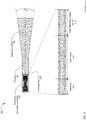
- FIG. 7 is a graphical representation of an amplified chirped laser for long range LIDAR systems.
- FIG. 8 is a block diagram of a scanning coherent LIDAR system.
- FIG. 9 is a block diagram of a scanning optical subsystem for use in a coherent LIDAR system.
- FIG. 10 is a block diagram of another scanning optical subsystem for use in a coherent LIDAR system.
- FIG. 11 is a block diagram of another scanning optical subsystem for use in a coherent LIDAR system.
- FIG. 12 is a block diagram of another scanning optical subsystem for use in a coherent LIDAR system.
- FIG. 13A is a graphical representation of temporal over-sampling.
- FIG. 13B is a graphical representation of spatial over-sampling.
- FIG. 14 is a block diagram of a coherent LIDAR system using spatial oversampling.
- FIG. 15 is a block diagram of a scanning optical subsystem for use in a coherent LIDAR system with spatial over-sampling.
- FIG. 16A is a block diagram of a single element is a staring coherent LIDAR system.
- FIG. 16B is a block diagram of a staring LIDAR system.
- FIG. 17 is a depiction of a staring LIDAR sensor array integrated on a single chip.
- LIDAR coherent chirped LIDAR
- LIDAR systems commonly incorporate semiconductor diode lasers and attempt to control the laser to produce a precisely linear chirped wave.
- the principles described in this patent can be more generally applied to any type of laser whose output frequency can be varied by changing one or more input parameters. These principles can also be applied to generating nonlinear chirps.
- Feedback-controlled chirped diode lasers measure the frequency output characteristic of the laser and use the measurement to provide closed-loop feedback to control the laser output frequency.
- measuring and controlling the rate of change of the laser output frequency typically requires a finite time interval.
- a fraction of the laser output power may be transmitted through an unbalanced (or asymmetric) Mach-Zehnder interferometer (MZI) and onto a photodetector.
- MZI Mach-Zehnder interferometer
- the output frequency of the beat signal produced by the MZI-photodetector is directly proportional to the slope of the frequency chirp (i.e., the rate of change of frequency with time).
- This closed-loop system can generate a precisely controlled linear chirp, but only works well if the chirp duration and the LIDAR measurement time are substantially longer that the time interval needed to measure and control the slope of the frequency chirp.
- the chirp rate of high-speed coherent LIDAR systems is dictated by the required resolution and image update rate. Some systems may use chirp durations or measurement times less than 1 microsecond. Closed-loop laser control, as described in the preceding paragraph, does not work for these high speed LIDAR systems, because the propagation delays in the feedback system (such as optical delays in the unbalanced MZI and the response time of the laser and any loop filters) are comparable to or larger than the chirp duration itself.
- the transmitter output in a coherent LIDAR system is a sequence of identical (at least in theory) frequency chirps that repeat periodically, as shown in FIG. 2A .
- Environmental fluctuations, such as temperature changes, that cause the laser performance to change with time typically have a time constant that is much larger than the chirp repetition period.
- FIG. 4 is a block diagram of a frequency modulated laser 400 suitable for use in a high speed LIDAR system.
- the system includes a laser device 410 that is driven by a laser driver circuit 415 that controls the frequency of the laser output.
- the laser device 410 may be a diode laser, in which case the laser driver 415 controls the output frequency of the laser 410 by varying an electrical current provided to an input of the laser 410 .
- the laser device 410 may be some other type of laser, in which case the laser driver 415 may control the output frequency of the laser 410 by varying one or more other parameters.
- a portion of the output beam from the laser 410 is extracted by an optical tap 420 and applied to an optical frequency discriminator 425 that provides a measurement of the rate of change of the output frequency of the laser output.
- the optical tap 420 may be a tap coupler as shown, an asymmetric beam splitter, or some other device that extracts a small portion of the laser output.
- the optical frequency discriminator may be, for example, an asymmetric MZI and photodetector as shown in FIG. 4 .
- the output of the photodetector is a signal having a frequency proportional to the rate of change of the laser frequency (the asymmetric MZI and photodetector operate exactly as described for the coherent LIDAR system 100 , with the “range” to the target determined by the difference in the length of the two legs of the MZI).
- the signal output from the photodetector will be a constant predetermined frequency.
- the output of the laser deviates from a linear chirp, a corresponding deviation will occur in the frequency of the signal output from the photodetector.
- a technique other than an asymmetric MZI and photodetector may be used for the optical frequency discriminator 425 .
- An error determination module 430 receives the output from the optical frequency discriminator 425 , and determines the deviation of the laser frequency from its intended value as a function of time during the chirp period.
- the error determination may be performed by hardware and/or by a processor executing a method, such as a Hilbert transform, implemented in software.
- the error determination for the present chirp (“chirp k”) is provided to a correction determination module 435 that determines a correction to be applied to the drive signal for a subsequent chirp k+1 or, more generally, a future chirp period, where the delay between the measurements and the future time period is less than the time constant of any environmental fluctuations.
- the correction module 435 may determine the correction to be applied to the future chirp using hardware and/or a processor executing a method implemented in software.
- the correction determination module 435 may determine the correction to be applied to the future chirp based upon the error determination and/or the correction for one or more prior chirps. For example, the correction determination module 435 may determine the correction to be applied to the future chirp based, at least in part, on a weighted sum or weighted average of the determined errors for two or more prior periods of the periodic frequency versus time function.
- the correction determination module 435 may determine the correction to be applied to the future chirp based, at least in part, on digital or analog filtering of the determined errors for one or more prior periods of the periodic frequency versus time function.
- the laser 400 will be subsequently refer to as a “state machine CHDL” because where the information about the current “state” of the chirp is fed back to influence the future state of the chirp.
- the laser frequency error can be determined from multiple and adaptively varying measurements and/or filters.
- the free spectral range of the asymmetric MZI may be varied to measure large discrepancies when the system is turned on (or when a parameter such as temperature is changed), but switched to higher sensitivities to measure small errors when the system is at or near steady state.
- the drive signal fed into the laser may also include open-loop pre-distortion to compensate for known nonlinearities in the laser characteristics and/or environmental compensation for known changes to the environment, such as a separate measurement of the temperature of the LIDAR system (which generates a known shift in laser operating parameters). The use of open-loop pre-distortion and/or environmental compensation may allow the laser 400 to reach a steady state quicker when the system is turned on or when an environmental parameter such as temperature is changed.
- the signal to noise ratio (SNR) required for good target detection determines the value of T M , and T M can be reduced by adjusting system parameters such as CHDL power or receiver collection aperture.
- the beam is scanned to the next pixel on the target.
- the total number of pixels that can be measured in a given time, termed the “3D imaging rate” (3D-IR) is (1 ⁇ 2T) pixels per second.
- the 3D-IR be as high as possible.
- the “speed of light limit” on the 3D imaging rate can be overcome with two improvements to the basic coherent LIDAR system of FIGS. 1, 2, and 3 .
- the first improvement as incorporated into the LIDAR system 500 of FIG. 5 , is to use two CHDLs 510 , 570 to simultaneously illuminate the same pixel on the target, with the frequencies of the CHDLs chirping in opposite directions.
- the frequency of the first CHDL 510 may follow a positive sawtooth function and the frequency of the second CHDL 570 may follow a negative sawtooth function.
- the frequency of the first CHDL 510 may follow a triangle function and the frequency of the second CHDL 570 may follow a triangle function shifted 180 degrees (shifted in time by one chirp period T) compared to the first CHDL. This enables the up and down measurements of FIG. 3 to be performed simultaneously.
- the LIDAR system 500 includes second CHDL 570 , which is chirped in the opposite direction as the first CHDL 510 .
- the first and second CHDLs 510 , 570 may be multiplexed by a beam combiner 575 .
- the first and second CHDLs 510 , 570 may have orthogonal polarization, and the beam combiner 575 may be a polarization beam splitter.
- the first and second CHDLs 510 , 570 may have different wavelengths, and the beam combiner 575 may be a dichroic beam splitter.
- the beams from the first and second CHDLs 510 , 570 are combined and directed to the target 560 .
- the reflected beams from the target are separated by beam divider (using polarization or wavelength as appropriate) are directed to separate detectors 550 , 585 .
- the time to obtain R and dR/dt for a pixel is T
- the 3D imaging rate is (1/T) pixels per second.
- the next improvement in the conventional coherent LIDAR system results from recognition that the speed of light fundamentally imposes a delay or latency in the measurement, rather than a restriction on the imaging rate.
- the improvement to overcome the speed of light limit is to not reset the chirp after every pixel, but instead to use a chirp with longer extent T′ that spans a number of (scanned) pixels as shown in FIG. 6 .
- the example of FIG. 6 illustrates the chirp extended over three pixels, with the reflection from each pixel measured during a respective measurement time.
- the previously described state machine CHDL can provide a precisely controlled linear chirp over a frequency range sufficient to allow a single chirp to span hundreds of scanned pixels.
- the effective 3D-IR ⁇ 1/T M which is solely limited by the measurement time and not the round-trip time to the target.
- Different pixels are effectively measured using chirped waves with different optical frequencies, which eliminates any ambiguity in their range measurements, and allows faster measurements than are possible with the conventional coherent LIDAR systems.
- the returns from different pixels can have different time delays and Doppler shifts. This does not pose a major problem, and can be accounted for by straightforward methods.
- a detector that measures the return signal from multiple pixels as the illumination beam is scanned across them is used in conjunction with sliding-window Fourier transforms that resolve the ambiguity in the data processing.
- a multiplicity of detectors is used along with the beam-scanning element. This embodiment takes advantage of the fact that the returned beam “lags” the illumination beam in a scanning system, creating a spatial separation between the two. The spatial separation is larger for farther ranges compared to nearer targets, and this fact is exploited by using a multiplicity of spatially staggered detectors where each one only measures the return signal from a subset of target ranges.
- LIDAR systems impose a stringent requirement on the number of photons that need to be collected by the coherent receiver in order to achieve accurate measurements of range and range-rate.
- the number of photons collected is determined by the transmitted laser power, the reflectivity of the target, and the size of the receiver collection optics.
- Long-range (i.e., longer than 100 meters) LIDAR systems benefit from the use of high output powers (e.g., 100 mW to 10 W) to minimize the size and complexity of the collection optics used in the coherent receiver.
- long-range coherent LIDAR systems also require very narrow laser line width, which is generally incompatible with high laser output power.
- Semiconductor lasers with narrow line widths typically have output powers less than 100 mW.
- a semiconductor laser may be used in conjunction with a semiconductor optical amplifier (SOA) or flared tapered amplifier in order to achieve the desired higher output powers while maintaining the required narrow line width.
- SOA semiconductor optical amplifier
- the output of a narrow line width master oscillator which may be a state machine CHDL, may be fed into an optical amplifier, typically in a semiconductor medium.
- the optical and spectral properties of the oscillator can be affected by optical feedback effects and coupling of amplified spontaneous emission (ASE) from the amplifier section to the oscillator, which can dramatically increase the line width.
- ASE amplified spontaneous emission
- a feedback barrier may be disposed between the CHDL and the amplifier to ensure that the line width and other properties of the CHDL are not affected by feedback from the amplifier section.
- the feedback barrier may be, for example, an optical isolator or an attenuator.
- a master-oscillator power-amplifier (MOPA) laser with a broad-area or flared/tapered amplifier can provide single-mode operation at high (i
- FIG. 7 is a schematic diagram of a narrow line width, high power, MOPA laser 700 suitable for use in long range coherent LIDAR systems.
- the MOPA laser 700 includes a feedback insensitive oscillator 710 , an optional feedback barrier 715 , a preamplifier 720 and a tapered amplifier 730 .
- the feedback insensitive oscillator which may be state machine CHDL as previously described, includes a laser cavity 714 sandwiched between a reflector 712 and a high reflectivity output mirror 716 . The frequency chirp of such an oscillator can be controlled precisely using the techniques described above.
- Insensitivity to optical feedback is achieved by increasing the reflectivity of the output mirror 716 , which ensures that most of the light fed back towards the oscillator 710 from the preamplifier and amplifier 720 , 730 does not affect the oscillation in the laser cavity 714 .
- Increasing the reflectivity of the output mirror effectively incorporates the feedback barrier 715 into the output mirror 716 .
- the increase in the reflectivity of the output mirror 716 will reduce the power output of the oscillator 710 .
- the reduction of oscillator output power is made up by the use of the preamplifier 720 between the oscillator 710 and the flared/tapered amplifier 730 to boost the optical power.
- the same effect of reducing the amount of optical power fed backwards into the laser can also be achieved using an optical loss element (such as a coupler/splitter or an absorbing section) as the feedback barrier 715 .
- This technique also reduces the optical power output of the oscillator, which can be compensated by the gain of the preamplifier 720 .
- LIDAR systems can be segregated into staring systems and scanning systems.
- a staring LIDAR the transmitted laser beam illuminates the entire scene to be imaged. Reflections from the entire scene are imaged onto a detector array, with each detector element in the array corresponding to respective pixel in the scene.
- a staring coherent LIDAR must spread the reflected and LO beam over the entire detector array, which leads to insufficient signal-to-noise ratio unless the available laser power is very high.
- coherent LIDAR systems typically use an optical system to scan the transmitted bean sequentially over the scene.
- a coherent receiver for a coherent LIDAR system employing a scanning transmitted beam has a fundamental architectural challenge.
- a transmitted beam having a beam diameter D 0 is scanned across the scene within a wide field of view ⁇ .
- the scanning is typically performed in two dimensions. However, the subsequent figures only show scanning in one direction for ease of representation. The same design can be easily extended to two-dimensional scanning.
- the size of the transmitted beam, D 0 is determined by the size of the scanning optic and the required angular resolution (typical values of D 0 are 1-3 mm).
- the coherent receiver has to modally overlap the received photons from the target with the LO wave on a photodetector.
- One solution for the coherent receiver is to use an imaging lens that images the entire field of view ⁇ on a fixed detector or detector array, and illuminate the entire detector area, whether it is a single large detector or a detector array, with the LO at all times.
- this fraction can be 1/10 5 or smaller
- this leads to an inefficient use of LO power and detector area, and can result in very poor signal to noise ratio due to LO shot noise.
- the receiver in a typical coherent LIDAR is typically scanned along with the transmitted beam. In other words, the LO beam needs to be mode-matched with the return beam from the scene as different parts of the field of view are illuminated.
- the effective collection aperture of the coherent receiver, D 1 is dictated by the requirement to collect enough photons from the target to make a high-SNR measurement.
- D 1 D 0
- the transmitted beam diameter and the receiver collection aperture may be the same.
- the LIDAR optical system can be a simple “cat's-eye” configuration (so-called because the transmitted and reflected light propagate in opposing directions along the same optical path, as is the case with light reflected from the eyes of a cat) where the return beam from the target retraces the optical path of the transmitted beam, as in the coherent LIDAR system 800 shown in FIG. 8 .
- the laser beam (other than the fraction extracted for the LO) is output from the circulator 830 and expanded/collimated by lens 870 to form an output beam having diameter D 0 .
- the lens 870 and all lenses in subsequent drawings, are depicted as single refractive lens elements but may be any combination of refractive, reflective, and/or diffractive elements to perform the required function.
- the output beam impinges upon scanning mirror 875 , which can be rotated about an axis 880 .
- the scanning mirror 875 may be, for example, a MEMS (micro-electro-mechanical system) mirror capable of high speed scanning. Rotation of the scanning mirror causes the output beam to scan across the scene through a field of view ⁇ .
- MEMS micro-electro-mechanical system
- Optic 870 captures (i.e., focuses) the reflected light, which is directed to the circulator 830 .
- the captured reflected light exits the circulator 830 and is combined with the LO beam and detected as previously described.
- the diameter D 0 of the transmitted beam and the collection aperture of the receiver are defined by the optic 870 .
- Increasing the diameter of the transmitted beam correspondingly increases the diameter of the receiver aperture (and thus the number of received photons) at the expense of increasing the size of the optic 870 and the scanning mirror 875 .
- the requirement for high speed scanning over the field of view limits the allowable size of the mirror.
- the transmitted beam diameter of scanning LIDAR systems is typically limited to 1 mm to 3 mm.
- the necessary diameter of the receiver aperture D 1 is preferably larger than the transmitted beam diameter D 0 , and the challenge is to ensure mode overlap between the received beam and the LO beam at the detector with sufficient signal-to-noise ratio.
- FIG. 9 is a schematic diagram of an optical system 900 for a scanning coherent LIDAR system in which a diameter D 1 of a receiver collection aperture may be substantially larger than a diameter D 0 of a transmitted beam 930 .
- a first lens 910 receives light from a CHDL and forms a collimated beam with a diameter D 0 .
- the collimated beam impinges on a scanning mirror 915 which is rotated to cause the beam to scan over a total scan angle ⁇ .
- a second lens 940 having a diameter D 1 , where D 1 >D 0 receives reflected light 935 from a target scene and forms an image of the target scene on a detector array or a single detector.
- an area of the detector array or single detector is equal to or larger than the scene image formed by the second lens 940 .
- the use of a detector array instead of a single detector ensures that the detector has a low enough capacitance to achieve the required bandwidth.
- Each detector in a detector array corresponds to a pixel in the scene and only one detector in the array is active for any given scan angle.
- the reflected light 935 received by the second lens 940 originates at a point in the target scene that is illuminated by the transmitted beam 930 .
- the received light is focused to a spot that movies laterally in the focal plane of the second lens 940 (i.e., across the plane of the detector 945 ).
- the spot of received light will scan in two dimensions across the detector 945 . Since the target is illuminated with a smaller beam than the collection optic, the spot size at the plane of the detector for a given angle of illumination is larger than the resolution-limited spot size of the lens.
- the LO beam and the received light be superimposed at the detector. It is possible to achieve this with an LO beam that illuminates the entire detector 945 . Since the received light forms a spot that scans across the detector 945 as the transmitted beams is scanned across the scene, it is advantageous for the LO beam to instead scan across the detector 945 in a corresponding manner. To this end, a portion of the transmitted beam is extracted by a tap beam splitter 920 to form the LO beam 925 . The LO beam is then combined with the received light 935 by a second beam splitter 950 .
- the angle of the LO beam changes in conjunction with the scanning of the transmitted beam.
- the tap beam splitter 920 and beam splitter 950 effectively form a corner reflector such that the LO beam is parallel to the received light when the LO and received beams are combined.
- the second lens 940 focuses the LO beam to a spot that superimposed on the spot of received light at the detector 945 .
- FIG. 10 is a schematic diagram of another optical system 1000 for a scanning coherent LIDAR system in which a diameter D 1 of a receiver collection aperture may be substantially larger than a diameter D 0 of a transmitted beam 1030 .
- a first lens 1010 receives light from a CHDL and forms a collimated beam with a diameter D 0 . The collimated beam impinges on a scanning mirror 1015 which is rotated to cause the beam to scan over a total scan angle ⁇ .
- a second lens 1040 having a diameter D 1 , where D 1 >D 0 receives reflected light 1035 from a target scene and forms an image of the target scene on a detector array or a single detector as previously described. At any given instant, the reflected light 1035 received by the second lens 1040 forms a spot that scans across the detector 1045 as previously described in conjunction with FIG. 9 .
- a third lens 1060 and a fourth lens 1065 form a 1:1 telescope that relays the transmitted beam 1030 from the scanning mirror 1015 to the scene.
- a portion of the transmitted beam is extracted by a tap beam splitter 1020 between the third and fourth lenses 1060 , 1065 to form the LO beam 1025 .
- the LO beam and the received light 1035 are combined by a second beam splitter 1050 .
- a relay lens 1070 in the path of the LO beam focuses the LO beam to a spot at the plane of the detector 1045 .
- the focal lengths of the third lens 1060 and the further lens 1065 are equal to the focal length of the second lens 1040 , the focused spot of the LO beam will have the same size as the focused spot of received light.
- FIG. 9 and FIG. 10 illustrate coherent LIDAR systems using separate optical paths for the transmitter and receiver
- a system with a single set of optics in the cat's-eye configuration minimizes the complexity of the photodetector and associated electronics complexity.
- the illumination beam needs to be transformed from a first beam diameter D 0 (which can be constrained by the practical size of the scanning mirror) to a second beam diameter D 1 >D 0 (and vice versa for the reflected light returning through the same optical path) without compromising the total field of view ⁇ .
- the number of optical modes, or unique angular positions, a beam can assume within a field of view is determined by the angular resolution of the beam.
- a beam with diameter D 0 has an angular resolution ⁇ /D 0 (ignoring constant scaling factors of order unity throughout this discussion). Therefore a beam with diameter D 0 can be scanned to fill out a certain number of optical modes N 0 ⁇ *D 0 / ⁇ within the field of view ⁇ .
- the total number of available optical modes remains constant when the diameter of the beam is magnified.
- a simple telescope that magnifies the beam diameter from D 0 to D 1 will reduce the total field of view from ⁇ to ⁇ /M to conserve the number of optical modes.
- the scanner will provide NO modes, with an angular resolution of ⁇ /MD 0 , distributed over a field of view of ⁇ /M.
- the NO modes must be spaced apart with an angular distance between adjacent modes of ⁇ /D 0 , such that the NO modes are sparsely distributed across the field of view ⁇ . This means that only a portion of each scene resolution element is illuminated as the transmitted beam is scanned over the scene. Practically this means that the LIDAR system images the same total field of view in the same measurement time by trading off scene pixel fill factor for an increase in the received optical power.
- a mode transformer may be used to transform a set of N 0 closely spaced modes spanning a field of view ⁇ /M into a set of NO modes that sparsely sample a field of view ⁇ .
- a mode transformer can be implemented by coupling each available mode into a respective single mode optical fiber, and then moving the fibers apart from each other to “sparsify” the modes.
- a collimating lens can then be used to convert the light from each optical fiber into a D1-sized beam.
- FIG. 11 is a schematic diagram of an optical system 1100 for a scanning coherent LIDAR system in which the available modes are distributed sparsely over the entire field of view ⁇ .
- a first lens 1110 receives light from a circulator, such as the circulator 130 in FIG. 1 , and forms a collimated beam with a diameter D 0 .
- the collimated beam is incident on a scanning mirror 1115 which rotates to scan the collimated beam through a scan angle corresponding to the field of view ⁇ .
- a second lens 1120 receives the scanning beam from the scan mirror 1115 and creates a moving array of spots at its focal plane.
- a microlens array (MLA) 1030 is placed at this focal plane, with each microlens matched to the spot size formed by the scanning beam passing through the second lens 1120 .
- Each element of the microlens array 1030 then converts (further focuses) the spot incident on it, thereby creating a sparse array of smaller spots at an image plan 1135 of the MLA.
- a third lens 1040 then collimates light from the array of smaller spots into a sparse, but now fully angularly-swept beam of larger size D 1 .
- the effective speeds (i.e., focal length divided by diameter, or f-number) of the microlenses and the third lens are matched. Reflected light received from the scene follows the reverse path to return to the circulator.
- the optical system 1100 creates an array of spots that samples the full angular field of view ⁇ at the angular resolution of the initial beam of size D 0 , while collecting more target photons corresponding to the larger beam size D 1
- the field of view ⁇ will be equal to the beam scan angle.
- the focal lengths of the second and third lenses 1120 , 1140 are unequal the field of view can be expanded or compressed compared to the beam scan angle.
- the optical system 1100 of FIG. 11 includes a wide-field of view third lens 1140 to form a scanning beam of diameter D 1 and to collect photons from the full field of view.
- FIG. 12 is a schematic diagram of an optical system 1200 in which the large lens 1140 of FIG. 11 is replaced by three smaller lenses 1240 A, 1240 B, 1240 C that each create D1-sized beams that only scan over one-third of the total field of view ⁇ .
- Folding mirrors 1250 A, 1250 B, 1250 C, 1250 D are used to “combine” the fields-of-view of the three lenses 1240 A, 1240 B, 1240 C to achieve the full angular field of view ⁇ .
- optical system 1200 has the advantage of using smaller optics and reducing overall system complexity by taking advantage of the fact that the size and complexity of optical elements tend to scale nonlinearly with the field of view.
- a different number of smaller lenses (rather than three), or different relay optics can be used instead (other than folding mirrors), to achieve the same desired result.
- the folding mirrors 1250 B, 1250 C before the microlens array 1230 , the large microlens array 1230 may be replaced by three smaller microlens arrays to achieve the same desired result, using appropriate relay optics.
- Coherent LIDAR measures the amplitude and phase of the electromagnetic field reflected from the target.
- This reflected field is strongly influenced by surface irregularities on the target within the illuminated spot. These irregularities result in random variations in the amplitude and phase of the reflected field, commonly known as speckle.
- speckle In most practical cases, the intensity of the reflected field has an exponential probability distribution and the phase has a uniform probability distribution. This means that even a bright target can occasionally have a low intensity and may be below the detection threshold of the LIDAR system.
- the spatial scale of the speckle variations is given by the resolution of the receiver optics. For example, in a conventional coherent LIDAR system, if the angular resolution of the LIDAR system is 0.1 degrees, the amplitude and phase of the speckle pattern change every 0.1 degrees.
- the process of integration works best if the multiple measurements being integrated are in some way uncorrelated from each other, so that the target fluctuations can be “averaged” out.
- Speckle in a LIDAR system is comparable to a fluctuating target in a RADAR system, and similar mathematical techniques can be applied to mitigate the effects of speckle.
- the goal of a high-speed coherent LIDAR system is to obtain range and Doppler information from every scene pixel in a single scan of the field of view.
- integration over multiple scans, as used in RADAR systems cannot be directly applied to a LIDAR system.
- FIG. 13A and FIG. 13B illustrate two approaches to obtain the multiple measurements.
- the common idea behind both approaches is to divide the pixel into N subpixels, perform separate LIDAR measurements on the subpixels, and coherently or incoherently integrate these measurements to provide a composite measurement for the pixel.
- each scene pixel 1310 is partitioned into N subpixels 1320 , where N is an integer greater than one, that are measured sequentially.
- N is an integer greater than one, that are measured sequentially.
- N 3.
- Each subpixel is measured using an illumination beam that is scanned across the pixel during the pixel measurement time T M (as defined in FIG. 1 ). The angular size of the illumination beam determines the subpixel size.
- a one-dimensional scan is shown in FIG. 13A for simplicity, but other scanning patterns are possible.
- N separate LIDAR measurements are sequentially performed over these subpixels (each measurement takes time T M /N), and these measurements are coherently or incoherently integrated to determine the range and/or range-rate of the pixel.
- a beam with a narrower angular size than the desired pixel size can be implemented in multiple ways, e.g., by using a scanning element with a larger aperture in the LIDAR system, or by using a magnifying optic such as a telescope or a diffraction grating to increase the size of the beam while using a scanner with a small aperture.
- a magnifying optic such as a telescope or a diffraction grating to increase the size of the beam while using a scanner with a small aperture.
- the (near-field) size of the beam at the LIDAR transmitter/receiver is inversely proportional to the angular size of the beam in the far field (i.e., at the target).
- the LIDAR measurements on N subpixels within a pixel can be performed simultaneously and in parallel, as illustrated in FIG. 13B .
- N the number of pixels within a pixel.
- the N subpixels are simultaneously illuminated and imaged on different photodetectors to obtain N different LIDAR measurements (range and/or range-rate).
- each measurement is performed over the full pixel measurement time T M .
- the N measurements are coherently or incoherently integrated to provide a composite range and/or range-rate of the pixel.
- a pixel may be divided into four subpixels (as in FIG. 13B ) which are scanned in two horizontal (as shown in FIG. 13A ) steps by two vertically-offset beams.
- FIG. 14 is a schematic diagram of a coherent LIDAR system 1400 that performs simultaneous measurements of N subpixels within each pixel.
- the system 1400 is similar to the LIDAR system 800 of FIG. 8 , but with N beams propagating in parallel though much of the system.
- the output of a CHDL 1410 is divided into N parallel beams.
- a tap coupler 1420 is used to extract a small fraction of each beam as a respective LO beam.
- the majority (typically >90%) of each CHDL beam is directed toward a target via an N-channel circulator 1430 .
- the N-channel circulator may be, for example, implemented using discrete optical elements (e.g. known combinations of polarizing beam splitters and a Faraday rotator) such that N beams can pass through the circulator in parallel.
- a lens 1470 converts the N output beams 1435 from the circulator 1430 into N collimated output beams at slightly different angles such that the N beams illuminate N subpixels within a target pixel, as shown in FIG. 13B .
- the N output beams are scanned across a field of view by a scanning mirror 1475 .
- the lens 1470 collects light reflected from the target (not shown) and forms the reflected light into N received light beams 1440 .
- the combined LO waves and the received light beams from the target are respectively incident on N photodetectors 1450 .
- the N photodetectors 1450 provide respective measurements indicative of the range and range rate of respective subpixels, as previously described.
- a processor (not shown) coherently or incoherently combines the N subpixel measurements to provide a composite range and/or range rate measurement for the pixel.
- FIG. 15 is a block diagram of a scanning optical 1500 system for a LIDAR that that performs simultaneous measurements of N subpixels within each pixel.
- the optical system 1500 is similar to the optical system 1100 of FIG. 11 , but with N beams propagating in parallel though much of the system.
- a first lens 1510 receives N beams from a circulator, such as the circulator 1430 in FIG. 14 , and forms N collimated beams with diameter D 0 .
- the collimated beams are incident on a scanning mirror 1515 at slightly different angles (not shown).
- the scanning mirror 1515 rotates to scan the N collimated beams through a scan angle corresponding to the field of view ⁇ .
- a second lens 1520 receives the N scanning beams from the scan mirror 1515 and creates a moving array of spots at its focal plane.
- a microlens array (MLA) 1530 is placed at this focal plane.
- the N beams from the circulator are configured such that each beam illuminates a single microlens in the MLA, and N microlenses are together illuminated.
- N smaller spots are formed at the image plane 1535 of the MLA. These N spots are formed into N slightly offset beams by the third lens 1540 that simultaneously illuminate N subpixels of the scene.
- a single beam from the circulator, with a different size, can be used instead of the N beams, to achieve the desired goal of simultaneously illuminating N microlenses after passing through the first lens 1510 , scanning element 1515 and second lens 1520 .
- the reflected light from these N subpixels is received by the third lens and propagates through the scanning optical system 1500 in the reverse direction, which results in N separate beams returned to the circulator, as was the case in the LIDAR system 1400 of FIG. 14 .
- the N beams of reflected light are then combined with respective LO beams.
- the combined beams are respectively incident on N photodetectors that provide respective measurements indicative of the range and range rate of respective subpixels.
- a processor (not shown) coherently or incoherently combines the N subpixel measurements to provide a composite range and/or range rate measurement for the pixel.
- a high-resolution coherent LIDAR or imaging system has two important components: i) a swept-frequency laser or “chirped laser” with a large frequency sweep range B to provide high axial resolution at the range of interest; and ii) a technique to translate the one-pixel (fixed (x,y)) measurement laterally in two dimensions to obtain a full 3-D image.
- Coherent LIDAR systems for 3-D imaging typically rely on the scanning of a one-pixel measurement across the scene to be image. Examples of scanning LIDAR systems were previously shown in FIGS. 8, 9, 10, 11, 12, 14 and 15 .
- An alternative to scanning LIDAR systems is a staring system consisting of a swept frequency laser, and a detection technique that is capable of capturing or measuring the 3-D image of a scene, or a multi-pixel portion of a scene concurrently.
- a staring system consisting of a swept frequency laser, and a detection technique that is capable of capturing or measuring the 3-D image of a scene, or a multi-pixel portion of a scene concurrently.
- Such a system has the potential to be inexpensive, robust, and contain no moving parts.
- FIG. 16A is a block diagram of one pixel of the detection side of a staring coherent LIDAR.
- a local oscillator beam having beam power of P LO and reflected light from a target pixel having power P tar are combined by a beam splitter.
- a balanced detector pair 1610 may be used to obtain a high dynamic range.
- the output of the balanced detector 1610 is amplified using a transimpedance amplifier (TIA) 1615 , digitized using an analog-to-digital converter (ADC) 1620 , and the spectrum of the photocurrent signal is calculated by a Digital Signal Processor (DSP) 1625 using a Fourier transform.
- the DSP 1625 may be on the chip containing the TIA 1615 and ADC 1620 , or external to the chip.
- This single pixel detector described above is extended to an N-element array (one-dimensional or two-dimensional) to implement the full-field 3-D imaging system as shown in FIG. 16B and
- FIG. 16B is a block diagram of a receiver array for full-field 3-D imaging where K pixels of the scene are simultaneously imaged.
- Two aligned detector arrays 1660 A 1660 B are used to perform the optical balancing.
- Each detector array contains K detectors to perform simultaneous measurements on K pixels of the scene.
- the detector arrays 1660 A, 1660 B may be located on separate chips/wafers or on a single wafer (using an external flip mirror or equivalent to align the two outputs of the beam splitter on the two detector arrays).
- balancing approaches may be implemented with a single photodetector array, e.g., using phase shifters, or polarization optics and pixelated polarizers, on adjacent pixels to introduce a it-phase shift on the LO or the target beam.
- phase shifters or polarization optics and pixelated polarizers
- pixelated polarizers on adjacent pixels to introduce a it-phase shift on the LO or the target beam.
- An unbalanced single detector array can also be used to perform the measurement, but this may limit the dynamic range of the system.
- the dynamic range can be improved by subtracting the common mode current from the photodetector using an external current source.
- the output of the detector arrays (whether K single detectors or 2K detectors to form K balanced pairs) is amplified with an array of TIAs 1665 , digitized with an array of ADCs 1670 , and one or more signal processors 1675 performs the Fourier transforms (typically using the FFT algorithm), the detection algorithms, and the input/output communication.
- the output of receiver array is typically two “images” (i.e., two values per pixel) corresponding to the depth map and the intensity of the reflections. Measuring the scene with alternate up- and down-chirps will also allow measuring the range rate of each scene pixel. Further data processing algorithms may also be implemented by the smart detector array or external processors.
- the various electronic components may be fully integrated on the same wafer substrate, e.g., silicon electronics with silicon or silicon-germanium detectors, or III-V semiconductor detectors and electronics.
- hybrid integration may be used where dies with different functionalities (detectors, amplifiers, mixed-mode circuits etc.) are incorporated on the substrate using pick-and-place techniques.
- Different functional elements may be spatially separated as shown schematically in this figure, or may be implemented as “composite pixels” that incorporate these different functional elements in close proximity to each other as shown in FIG. 17 .
- FIG. 17 is a block diagram of an alternative implementation of a receiver array 1700 where the detectors 1710 , TIA 1715 , ADC 1720 , and other electronic components are integrated, monolithically or using hybrid integration, in close proximity to form a series of functional unit cells 1705 . As shown in FIG. 17 , two adjacent detectors 1710 are used for balancing. This approach can be readily modified to use a single detector per unit cell, or the unit cell may only contain some functional blocks, with the remaining functions being performed separately.
- “plurality” means two or more. As used herein, a “set” of items may include one or more of such items.
- the terms “comprising”, “including”, “carrying”, “having”, “containing”, “involving”, and the like are to be understood to be open-ended, i.e., to mean including but not limited to. Only the transitional phrases “consisting of” and “consisting essentially of”, respectively, are closed or semi-closed transitional phrases with respect to claims.
Landscapes
- Physics & Mathematics (AREA)
- Engineering & Computer Science (AREA)
- General Physics & Mathematics (AREA)
- Computer Networks & Wireless Communication (AREA)
- Radar, Positioning & Navigation (AREA)
- Remote Sensing (AREA)
- Electromagnetism (AREA)
- Optics & Photonics (AREA)
- Condensed Matter Physics & Semiconductors (AREA)
- Nonlinear Science (AREA)
- Optical Radar Systems And Details Thereof (AREA)
Abstract
Description
ω=ω0 +ξt, (1)
-
- where ω=optical frequency of the laser output wave;
- ω0=a baseline frequency at the start of each chirp;
- ξ=a chirp rate measured in frequency per unit time; and
- t=time.
- where ω=optical frequency of the laser output wave;
τ=2R/c (2)
-
- where τ=the time interval between the output and reflected chirps=the round-trip time to the target;
- R=the range the target; and
- c=the speed of light.
The chirp period T must be longer than the round trip time to the target τ to provide a measurement interval TM. The required length of the measurement interval TM is determined by, among other factors, the signal-to-noise ratio of the reflected beam. At any given time during the measurement interval TM, the frequency difference Δω between the output and reflected waves is given by:
Δω=ξτ. (3)
- where τ=the time interval between the output and reflected chirps=the round-trip time to the target;
i≈(P LO P Ref)1/2 cos(Δωt+ω 0τ) (4)
-
- where i=current output from the photodetector; and
- PLO, PREF=power of the LO and reflected waves.
Δω can be determined by processing the output current from the photodetector. For example, the current value may be digitized with a sample rate substantially higher than the anticipated value of Δω. A Fourier transform or other process may be performed on the digitized samples to determine Δω. Alternatively, Δω may be determined by a bank of hardware filters or some other technique. The range R to the target may then be determined by
R=Δωc/2ξ (5) - where c=the speed of light.
The resolution of the range measurement is given by
ωD=2π/λ(dR/dt) (7)
-
- where ωD=Doppler frequency shift in the reflected beam;
- λ=the laser wavelength; and
- dR/dt=the rate of change of the range to the target.
- where ωD=Doppler frequency shift in the reflected beam;
Δω+ =ωD+ξτ; (8)
-
- where Δω+=the frequency difference between the output and reflected waves for an up-chirp.
When a target is illuminated with a laser beam with a down-chirp (i.e., a beam that decreases in frequency with time), the Doppler shift and the frequency shift due to the delay of the reflected beam are subtractive, such that
Δω− =ωD−ξτ; (9) - where Δω−=the frequency difference between the output and reflected waves for a down-chirp.
Illuminating a target with both an up-chirp beam and a down-chirp beam, concurrently or sequentially, allows determination of both range and range-rate. For example, the optical frequency of a single CHDL can be modulated to follow a linear triangular function, as shown inFIG. 3 , to provide sequential up-chirp and down-chirp measurements. Simultaneous determination of range and range rate is a major advantage of coherent LIDAR systems that enables faster and better target tracking in a variety of applications.
- where Δω+=the frequency difference between the output and reflected waves for an up-chirp.
3D-IR<½τmax =c/4R max. (8)
This is a limitation imposed by the finite speed of light c. For example, for a maximum range of 300 m, the 3D imaging rate is limited to 0.25 million pixels per second. This limitation may not be acceptable in some applications.
Claims (23)
Priority Applications (3)
| Application Number | Priority Date | Filing Date | Title |
|---|---|---|---|
| US16/032,535 US11187807B2 (en) | 2017-07-24 | 2018-07-11 | Precisely controlled chirped diode laser and coherent lidar system |
| US16/107,841 US11555923B2 (en) | 2017-07-24 | 2018-08-21 | LIDAR system with speckle mitigation |
| US17/505,640 US12038511B2 (en) | 2017-07-24 | 2021-10-20 | Precisely controlled chirped diode laser and coherent LIDAR system |
Applications Claiming Priority (3)
| Application Number | Priority Date | Filing Date | Title |
|---|---|---|---|
| US201762536425P | 2017-07-24 | 2017-07-24 | |
| US201862675567P | 2018-05-23 | 2018-05-23 | |
| US16/032,535 US11187807B2 (en) | 2017-07-24 | 2018-07-11 | Precisely controlled chirped diode laser and coherent lidar system |
Related Child Applications (2)
| Application Number | Title | Priority Date | Filing Date |
|---|---|---|---|
| US16/107,841 Continuation-In-Part US11555923B2 (en) | 2017-07-24 | 2018-08-21 | LIDAR system with speckle mitigation |
| US17/505,640 Continuation US12038511B2 (en) | 2017-07-24 | 2021-10-20 | Precisely controlled chirped diode laser and coherent LIDAR system |
Publications (2)
| Publication Number | Publication Date |
|---|---|
| US20190025431A1 US20190025431A1 (en) | 2019-01-24 |
| US11187807B2 true US11187807B2 (en) | 2021-11-30 |
Family
ID=65018576
Family Applications (2)
| Application Number | Title | Priority Date | Filing Date |
|---|---|---|---|
| US16/032,535 Active 2040-04-28 US11187807B2 (en) | 2017-07-24 | 2018-07-11 | Precisely controlled chirped diode laser and coherent lidar system |
| US17/505,640 Active 2038-11-17 US12038511B2 (en) | 2017-07-24 | 2021-10-20 | Precisely controlled chirped diode laser and coherent LIDAR system |
Family Applications After (1)
| Application Number | Title | Priority Date | Filing Date |
|---|---|---|---|
| US17/505,640 Active 2038-11-17 US12038511B2 (en) | 2017-07-24 | 2021-10-20 | Precisely controlled chirped diode laser and coherent LIDAR system |
Country Status (1)
| Country | Link |
|---|---|
| US (2) | US11187807B2 (en) |
Cited By (1)
| Publication number | Priority date | Publication date | Assignee | Title |
|---|---|---|---|---|
| US20220043155A1 (en) * | 2017-07-24 | 2022-02-10 | Intel Corporation | Precisely controlled chirped diode laser and coherent lidar system |
Families Citing this family (49)
| Publication number | Priority date | Publication date | Assignee | Title |
|---|---|---|---|---|
| US10707837B2 (en) * | 2017-07-06 | 2020-07-07 | Analog Photonics LLC | Laser frequency chirping structures, methods, and applications |
| US10775485B2 (en) * | 2017-10-20 | 2020-09-15 | Korea Electronics Technology Institute | LIDAR device and system comprising the same |
| US11536805B2 (en) | 2018-06-25 | 2022-12-27 | Silc Technologies, Inc. | Optical switching for tuning direction of LIDAR output signals |
| US12535586B2 (en) | 2018-08-31 | 2026-01-27 | SiLC Technology, Inc. | Reduction of ADC sampling rates in LIDAR systems |
| DE102018216636B4 (en) * | 2018-09-27 | 2020-06-04 | Carl Zeiss Smt Gmbh | Device for scanning the distance of an object |
| US11079480B2 (en) | 2018-12-29 | 2021-08-03 | Gm Cruise Holdings Llc | FMCW lidar with wavelength diversity |
| US11624810B2 (en) * | 2019-02-09 | 2023-04-11 | Silc Technologies, Inc. | LIDAR system with reduced speckle sensitivity |
| US11366206B2 (en) * | 2019-03-18 | 2022-06-21 | Aeva, Inc. | Lidar apparatus with an optical amplifier in the return path |
| US11385332B2 (en) * | 2019-03-20 | 2022-07-12 | Aeva, Inc. | LIDAR system with a mode field expander |
| EA202190115A1 (en) * | 2019-05-17 | 2021-03-25 | Байоксэл Терапьютикс, Инк. | FILM FORMULATIONS CONTAINING DEXMEDETOMIDINE AND METHODS FOR THEIR PREPARATION |
| US12429569B2 (en) | 2019-05-17 | 2025-09-30 | Silc Technologies, Inc. | Identification of materials illuminated by LIDAR systems |
| US11448732B2 (en) * | 2019-05-21 | 2022-09-20 | Northrop Grumman Systems Corporation | Frequency modulated scanning LIDAR with 360 degrees field of view |
| US11650317B2 (en) | 2019-06-28 | 2023-05-16 | Silc Technologies, Inc. | Use of frequency offsets in generation of LIDAR data |
| FR3099587B1 (en) * | 2019-07-31 | 2021-08-27 | Thales Sa | COHERENT LIDAR AND ASSOCIATED LIDAR IMAGING METHOD |
| EP3822658A1 (en) * | 2019-11-15 | 2021-05-19 | Aptiv Technologies Limited | Method and system for processing laser signal taken by laser device |
| CN111007483B (en) * | 2019-12-24 | 2022-06-28 | 联合微电子中心有限责任公司 | Laser radar based on silicon optical chip |
| US11754711B2 (en) * | 2019-12-31 | 2023-09-12 | Luminar Technologies, Inc. | Frequency chirp for lidar for high-velocity targets |
| US11480662B2 (en) | 2020-02-12 | 2022-10-25 | Aptiv Technologies Limited | Fast-scanning frequency-modulated continuous wave (FMCW) lidar systems |
| US11378748B1 (en) * | 2020-02-26 | 2022-07-05 | Board Of Trustees Of The University Of Alabama, For And On Behalf Of The University Of Alabama In Huntsville | Optical frequency discriminators based on fiber Bragg gratings |
| CN111257852B (en) * | 2020-04-03 | 2021-12-07 | 厦门大学 | Coherent laser radar and water flow velocity detection method |
| EP3916424B1 (en) * | 2020-05-25 | 2024-10-09 | Scantinel Photonics GmbH | Device and method for scanning measurement of the distance to an object |
| EP4162297A4 (en) * | 2020-06-08 | 2023-10-18 | Pointcloud Inc. | MICROLENS ARRAY LIDAR SYSTEM |
| EP4170387A4 (en) * | 2020-06-30 | 2023-07-05 | Huawei Technologies Co., Ltd. | RADAR DETECTION METHOD AND ASSOCIATED DEVICE |
| WO2022000333A1 (en) * | 2020-06-30 | 2022-01-06 | 华为技术有限公司 | Radar detection method and related device |
| US11740338B2 (en) | 2020-07-02 | 2023-08-29 | Aptiv Technologies Limited | Resolving return signals among pixels in frequency-modulated continuous-wave (FMCW) lidar systems |
| US11971508B2 (en) | 2020-07-08 | 2024-04-30 | Aptiv Technologies AG | Varying waveforms across frames in frequency-modulated continuous-wave (FMCW) lidar systems |
| FR3112397B1 (en) * | 2020-07-10 | 2022-08-12 | Commissariat Energie Atomique | Coherent lidar system with improved signal-to-noise ratio |
| US12210122B2 (en) * | 2020-08-26 | 2025-01-28 | Infineon Technologies Ag | Mirror movement and laser shoot pattern compensation for frequency-modulated continous-wave (FMCW) LIDAR |
| DE102020123557A1 (en) * | 2020-09-09 | 2022-03-10 | OSRAM Opto Semiconductors Gesellschaft mit beschränkter Haftung | OPTICAL MEASURING SYSTEM AND METHOD OF MEASURING A DISTANCE OR A VELOCITY OF AN OBJECT |
| WO2022101349A1 (en) * | 2020-11-11 | 2022-05-19 | Tørring Invest As | Ranging detection |
| WO2022167619A1 (en) * | 2021-02-05 | 2022-08-11 | Tørring Invest As | High speed hybrid scanning |
| US11811456B2 (en) * | 2021-03-30 | 2023-11-07 | Honeywell International Inc. | Multi-pixel waveguide optical receiver |
| US12541009B2 (en) | 2021-06-17 | 2026-02-03 | Silc Technologies, Inc. | Scanning multiple LIDAR system output signals |
| US12541027B2 (en) * | 2021-09-16 | 2026-02-03 | Aurora Operations, Inc. | Lidar simulation system |
| US12411213B2 (en) | 2021-10-11 | 2025-09-09 | Silc Technologies, Inc. | Separation of light signals in a LIDAR system |
| US12313558B2 (en) * | 2021-12-01 | 2025-05-27 | Thermo Electron Scientific Instruments Llc | Supercontinuum laser based web gauging system |
| CN116338671B (en) | 2021-12-24 | 2025-11-28 | 深圳市速腾聚创科技有限公司 | Linear frequency modulation nonlinear calibration method and device for optical signals, medium and equipment |
| US12216051B2 (en) * | 2022-01-21 | 2025-02-04 | Onto Innovation Inc. | Dynamic phase-shift interferometer utilizing a synchronous optical frequency-shift |
| US12553995B2 (en) | 2022-02-14 | 2026-02-17 | Silc Technologies, Inc. | Data refinement in optical systems |
| US12578443B2 (en) | 2022-04-23 | 2026-03-17 | Silc Technologies, Inc. | Data refinement in optical imaging systems |
| CN115144812B (en) * | 2022-07-28 | 2025-07-29 | 苏州市江海通讯发展实业有限公司 | Combined searching system based on time difference measurement |
| US12422618B2 (en) | 2022-10-13 | 2025-09-23 | Silc Technologies, Inc. | Buried taper with reflecting surface |
| CN115656983B (en) * | 2022-12-08 | 2023-03-28 | 武汉聚合光子技术有限公司 | Continuous laser for coherent laser radar |
| US20240264289A1 (en) * | 2023-02-07 | 2024-08-08 | Silc Technologies, Inc. | Data refinement in optical systems |
| US12578439B2 (en) | 2023-04-11 | 2026-03-17 | Silc Technologies, Inc. | Increasing resolution in imaging systems |
| KR102620196B1 (en) * | 2023-05-11 | 2024-01-02 | 람다이노비전 주식회사 | Laser Oscillation Apparatus Capable of Stabilizing Frequency Characteristics of Laser to Be Oscillated |
| JP2025148218A (en) * | 2024-03-25 | 2025-10-07 | 富士フイルム株式会社 | Measuring device and method |
| DE102024208245A1 (en) * | 2024-08-30 | 2026-03-05 | Zf Friedrichshafen Ag | Lidar sensor for the unambiguous detection of objects |
| CN120750862B (en) * | 2025-08-31 | 2025-10-31 | 湖南师范大学 | Optimization of periodic traffic transmission for distributed model training |
Citations (7)
| Publication number | Priority date | Publication date | Assignee | Title |
|---|---|---|---|---|
| US20070273863A1 (en) * | 2004-12-17 | 2007-11-29 | The Boeing Company | Ultra-linear signal processing for radar and laser radar |
| US8175126B2 (en) | 2008-10-08 | 2012-05-08 | Telaris, Inc. | Arbitrary optical waveform generation utilizing optical phase-locked loops |
| JP2013002949A (en) * | 2011-06-16 | 2013-01-07 | Toshiba Corp | Signal generation circuit and radar device |
| US20160299228A1 (en) | 2015-04-07 | 2016-10-13 | Oewaves, Inc. | Compact LIDAR System |
| US9559486B2 (en) * | 2009-04-29 | 2017-01-31 | Montana State University | Precise broadband frequency modulated laser |
| US9864060B2 (en) * | 2005-02-14 | 2018-01-09 | Digital Signal Corporation | Chirped coherent laser radar system and method |
| US20180031678A1 (en) | 2016-07-28 | 2018-02-01 | Strobe, Inc. | Distributed Vehicle Lidar System |
Family Cites Families (7)
| Publication number | Priority date | Publication date | Assignee | Title |
|---|---|---|---|---|
| US5373460A (en) * | 1993-03-11 | 1994-12-13 | Marks, Ii; Robert J. | Method and apparatus for generating sliding tapered windows and sliding window transforms |
| CN101876705A (en) * | 2009-11-03 | 2010-11-03 | 清华大学 | Frequency Domain Vehicle Detection Method Based on Single Frequency Continuous Wave Radar |
| US9915726B2 (en) * | 2012-03-16 | 2018-03-13 | Continental Advanced Lidar Solutions Us, Llc | Personal LADAR sensor |
| CN103630888B (en) * | 2013-02-27 | 2017-03-22 | 中国科学院电子学研究所 | High-precision real-time microwave velocity and distance measuring device based on symmetrical triangle LFMCW (Linear Frequency Modulation Continuous Wave) radar |
| US10649088B1 (en) * | 2015-01-13 | 2020-05-12 | DSCG Solutions, Inc. | Absolute object position location identification |
| US10976417B2 (en) * | 2017-03-29 | 2021-04-13 | Luminar Holdco, Llc | Using detectors with different gains in a lidar system |
| US11187807B2 (en) * | 2017-07-24 | 2021-11-30 | Intel Corporation | Precisely controlled chirped diode laser and coherent lidar system |
-
2018
- 2018-07-11 US US16/032,535 patent/US11187807B2/en active Active
-
2021
- 2021-10-20 US US17/505,640 patent/US12038511B2/en active Active
Patent Citations (7)
| Publication number | Priority date | Publication date | Assignee | Title |
|---|---|---|---|---|
| US20070273863A1 (en) * | 2004-12-17 | 2007-11-29 | The Boeing Company | Ultra-linear signal processing for radar and laser radar |
| US9864060B2 (en) * | 2005-02-14 | 2018-01-09 | Digital Signal Corporation | Chirped coherent laser radar system and method |
| US8175126B2 (en) | 2008-10-08 | 2012-05-08 | Telaris, Inc. | Arbitrary optical waveform generation utilizing optical phase-locked loops |
| US9559486B2 (en) * | 2009-04-29 | 2017-01-31 | Montana State University | Precise broadband frequency modulated laser |
| JP2013002949A (en) * | 2011-06-16 | 2013-01-07 | Toshiba Corp | Signal generation circuit and radar device |
| US20160299228A1 (en) | 2015-04-07 | 2016-10-13 | Oewaves, Inc. | Compact LIDAR System |
| US20180031678A1 (en) | 2016-07-28 | 2018-02-01 | Strobe, Inc. | Distributed Vehicle Lidar System |
Non-Patent Citations (11)
| Title |
|---|
| A. Dieckmann, "FMCW-LIDAR with tunable twin-guide laser diode", Journal, Electronic Letters, vol. 30, No. 4, published Feb. 17, 1994, 2 pages. |
| Amann et al., "Laser ranging: a critical review of usual techniques for distance measurement", Journal, Opt. Eng. 40(1)10-19, published Jan. 1, 2001, 10 total pages. |
| Choma et al., "Swept source optical coherence tomography using an all-fiber 1300-nm ring laser source", Journal, Journal of Biomedical Optics 10(4), 044009, published Jul./Aug. 2005, 6 total pages. |
| Dubey et al., "Fingerprint detection using full-field swept-source optical coherence tomography", Journal, Appl. Phys. Lett. 91, 181106 (2007), published Oct. 30, 2007, 4 total pages. |
| Jedrzejczyk et al., "High-power distributed-feedback tapered master-oscillator power amplifiers emitting at 1064 nm", Journal, https://www.spiedigitallibrary.org/conference-proceedings-of-spie, last accessed Jun. 22, 2018, 11 total pages. |
| Lang et al., "Numerical Analysis of Flared Semiconductor Laser Amplifiers", Journal, IEEE Journal of Quantum Electronics, vol. 29, No. 6, Published Jun. 1993, 8 total pages. |
| Leung et al., "High-power wavelength-swept laser in Littman telescope-less polygon filter and dual-amplifier configuration for multichannel optical coherence tomography", Journal, Optics Letters / vol. 34, No. 18, published Sep. 15, 2009, 3 pages. |
| Marron et al., "Three-dimensional imaging using a tunable laser source", Journal, Opt. Eng. 39(1) 47-51, https://www.spiedigitallibrary.org/journals/Optical-Engineering, last accessed Jun. 22, 2018, 5 pages. |
| Ndiaye et al., "Profilometry using a frequency-shifted feedback laser", Journal, 2005 Conference on Lasers & Electro-Optics (CLEO), published Jan. 16, 2006, 3 pages. |
| Santis et al., High-coherence semiconductor lasers based on integral high-Q resonators in hybrid Si/III-V platforms, Journal, PNAS, vol. 111, No. 8, published Feb. 25, 2014, pp. 2879-2884. |
| Satyan et al., Precise control of broadband frequency chirps using optoelectronic feedback, Journal, Optics Express 15991, vol. 17, No. 18, published, Aug. 31, 2009, 9 pages. |
Cited By (2)
| Publication number | Priority date | Publication date | Assignee | Title |
|---|---|---|---|---|
| US20220043155A1 (en) * | 2017-07-24 | 2022-02-10 | Intel Corporation | Precisely controlled chirped diode laser and coherent lidar system |
| US12038511B2 (en) * | 2017-07-24 | 2024-07-16 | Intel Corporation | Precisely controlled chirped diode laser and coherent LIDAR system |
Also Published As
| Publication number | Publication date |
|---|---|
| US20220043155A1 (en) | 2022-02-10 |
| US12038511B2 (en) | 2024-07-16 |
| US20190025431A1 (en) | 2019-01-24 |
Similar Documents
| Publication | Publication Date | Title |
|---|---|---|
| US12038511B2 (en) | Precisely controlled chirped diode laser and coherent LIDAR system | |
| US11555923B2 (en) | LIDAR system with speckle mitigation | |
| US20240230868A1 (en) | Performing speckle reduction using polarization | |
| US12078759B2 (en) | Techniques for spectral scanning in a LIDAR system | |
| US11740340B2 (en) | Techniques for amplification of return signal in LIDAR system | |
| US12298440B2 (en) | Techniques for performing speckle reduction using polarized light | |
| CN113841062B (en) | LIDAR system with mode field expander | |
| CN112764050B (en) | Laser radar measurement method and laser radar system | |
| CN114460601B (en) | Laser radar system | |
| CN112147636A (en) | Laser radar and detection method of laser radar | |
| EP3973314A1 (en) | 360 degrees field of view scanning lidar with no movable parts | |
| EP3973313A1 (en) | Methods for large angle field of view scanning lidar with no movable parts | |
| JP7315154B2 (en) | Distance and speed measuring device | |
| Prost et al. | Monolithically integrated silicon photonic biaxial FMCW LiDAR for scalable 3D sensing | |
| US20240377534A1 (en) | Lidar with seed modulated semiconductor optical amplifier for enhanced signal to noise ratio | |
| US20240410999A1 (en) | Techniques for a free space silicon photonics receiver for fmcw lidar | |
| CA3141215C (en) | Methods for large angle field of view scanning lidar with no movable parts | |
| US20240255722A1 (en) | Techniques for alignment of target and local oscillator beams to photodiode detector |
Legal Events
| Date | Code | Title | Description |
|---|---|---|---|
| AS | Assignment |
Owner name: TELARIS INC., CALIFORNIA Free format text: ASSIGNMENT OF ASSIGNORS INTEREST;ASSIGNORS:SATYAN, NARESH;RAKULJIC, GEORGE;REEL/FRAME:046320/0842 Effective date: 20180710 |
|
| FEPP | Fee payment procedure |
Free format text: ENTITY STATUS SET TO UNDISCOUNTED (ORIGINAL EVENT CODE: BIG.); ENTITY STATUS OF PATENT OWNER: LARGE ENTITY |
|
| FEPP | Fee payment procedure |
Free format text: ENTITY STATUS SET TO SMALL (ORIGINAL EVENT CODE: SMAL); ENTITY STATUS OF PATENT OWNER: LARGE ENTITY |
|
| STPP | Information on status: patent application and granting procedure in general |
Free format text: APPLICATION DISPATCHED FROM PREEXAM, NOT YET DOCKETED |
|
| AS | Assignment |
Owner name: INTEL CORPORATION, CALIFORNIA Free format text: ASSIGNMENT OF ASSIGNORS INTEREST;ASSIGNOR:TELARIS, INC.;REEL/FRAME:048388/0879 Effective date: 20190220 |
|
| FEPP | Fee payment procedure |
Free format text: ENTITY STATUS SET TO UNDISCOUNTED (ORIGINAL EVENT CODE: BIG.); ENTITY STATUS OF PATENT OWNER: LARGE ENTITY |
|
| STPP | Information on status: patent application and granting procedure in general |
Free format text: DOCKETED NEW CASE - READY FOR EXAMINATION |
|
| STPP | Information on status: patent application and granting procedure in general |
Free format text: NON FINAL ACTION MAILED |
|
| STPP | Information on status: patent application and granting procedure in general |
Free format text: RESPONSE TO NON-FINAL OFFICE ACTION ENTERED AND FORWARDED TO EXAMINER |
|
| STPP | Information on status: patent application and granting procedure in general |
Free format text: NOTICE OF ALLOWANCE MAILED -- APPLICATION RECEIVED IN OFFICE OF PUBLICATIONS |
|
| STPP | Information on status: patent application and granting procedure in general |
Free format text: NOTICE OF ALLOWANCE MAILED -- APPLICATION RECEIVED IN OFFICE OF PUBLICATIONS |
|
| STPP | Information on status: patent application and granting procedure in general |
Free format text: PUBLICATIONS -- ISSUE FEE PAYMENT VERIFIED |
|
| STCF | Information on status: patent grant |
Free format text: PATENTED CASE |
|
| CC | Certificate of correction | ||
| MAFP | Maintenance fee payment |
Free format text: PAYMENT OF MAINTENANCE FEE, 4TH YEAR, LARGE ENTITY (ORIGINAL EVENT CODE: M1551); ENTITY STATUS OF PATENT OWNER: LARGE ENTITY Year of fee payment: 4 |