EP3933193A1 - Flüssigkeitszuführsystem - Google Patents
Flüssigkeitszuführsystem Download PDFInfo
- Publication number
- EP3933193A1 EP3933193A1 EP20183132.8A EP20183132A EP3933193A1 EP 3933193 A1 EP3933193 A1 EP 3933193A1 EP 20183132 A EP20183132 A EP 20183132A EP 3933193 A1 EP3933193 A1 EP 3933193A1
- Authority
- EP
- European Patent Office
- Prior art keywords
- lance
- liquid
- level
- removal
- supply system
- Prior art date
- Legal status (The legal status is an assumption and is not a legal conclusion. Google has not performed a legal analysis and makes no representation as to the accuracy of the status listed.)
- Pending
Links
- 239000007788 liquid Substances 0.000 title claims abstract description 148
- 238000000034 method Methods 0.000 claims abstract description 14
- 238000001514 detection method Methods 0.000 claims description 9
- 230000007423 decrease Effects 0.000 description 8
- 239000000126 substance Substances 0.000 description 5
- 230000003247 decreasing effect Effects 0.000 description 3
- 235000014676 Phragmites communis Nutrition 0.000 description 1
- 238000011109 contamination Methods 0.000 description 1
- 230000001419 dependent effect Effects 0.000 description 1
- 230000000694 effects Effects 0.000 description 1
- 238000003780 insertion Methods 0.000 description 1
- 230000037431 insertion Effects 0.000 description 1
- 230000007257 malfunction Effects 0.000 description 1
- 238000004519 manufacturing process Methods 0.000 description 1
- 238000005259 measurement Methods 0.000 description 1
- 238000005086 pumping Methods 0.000 description 1
Images
Classifications
-
- B—PERFORMING OPERATIONS; TRANSPORTING
- B65—CONVEYING; PACKING; STORING; HANDLING THIN OR FILAMENTARY MATERIAL
- B65D—CONTAINERS FOR STORAGE OR TRANSPORT OF ARTICLES OR MATERIALS, e.g. BAGS, BARRELS, BOTTLES, BOXES, CANS, CARTONS, CRATES, DRUMS, JARS, TANKS, HOPPERS, FORWARDING CONTAINERS; ACCESSORIES, CLOSURES, OR FITTINGS THEREFOR; PACKAGING ELEMENTS; PACKAGES
- B65D25/00—Details of other kinds or types of rigid or semi-rigid containers
- B65D25/38—Devices for discharging contents
- B65D25/40—Nozzles or spouts
- B65D25/48—Separable nozzles or spouts
-
- F—MECHANICAL ENGINEERING; LIGHTING; HEATING; WEAPONS; BLASTING
- F04—POSITIVE - DISPLACEMENT MACHINES FOR LIQUIDS; PUMPS FOR LIQUIDS OR ELASTIC FLUIDS
- F04B—POSITIVE-DISPLACEMENT MACHINES FOR LIQUIDS; PUMPS
- F04B13/00—Pumps specially modified to deliver fixed or variable measured quantities
-
- F—MECHANICAL ENGINEERING; LIGHTING; HEATING; WEAPONS; BLASTING
- F04—POSITIVE - DISPLACEMENT MACHINES FOR LIQUIDS; PUMPS FOR LIQUIDS OR ELASTIC FLUIDS
- F04B—POSITIVE-DISPLACEMENT MACHINES FOR LIQUIDS; PUMPS
- F04B23/00—Pumping installations or systems
- F04B23/02—Pumping installations or systems having reservoirs
- F04B23/025—Pumping installations or systems having reservoirs the pump being located directly adjacent the reservoir
-
- F—MECHANICAL ENGINEERING; LIGHTING; HEATING; WEAPONS; BLASTING
- F04—POSITIVE - DISPLACEMENT MACHINES FOR LIQUIDS; PUMPS FOR LIQUIDS OR ELASTIC FLUIDS
- F04B—POSITIVE-DISPLACEMENT MACHINES FOR LIQUIDS; PUMPS
- F04B49/00—Control, e.g. of pump delivery, or pump pressure of, or safety measures for, machines, pumps, or pumping installations, not otherwise provided for, or of interest apart from, groups F04B1/00 - F04B47/00
- F04B49/02—Stopping, starting, unloading or idling control
- F04B49/025—Stopping, starting, unloading or idling control by means of floats
-
- F—MECHANICAL ENGINEERING; LIGHTING; HEATING; WEAPONS; BLASTING
- F04—POSITIVE - DISPLACEMENT MACHINES FOR LIQUIDS; PUMPS FOR LIQUIDS OR ELASTIC FLUIDS
- F04B—POSITIVE-DISPLACEMENT MACHINES FOR LIQUIDS; PUMPS
- F04B49/00—Control, e.g. of pump delivery, or pump pressure of, or safety measures for, machines, pumps, or pumping installations, not otherwise provided for, or of interest apart from, groups F04B1/00 - F04B47/00
- F04B49/04—Regulating by means of floats
-
- F—MECHANICAL ENGINEERING; LIGHTING; HEATING; WEAPONS; BLASTING
- F04—POSITIVE - DISPLACEMENT MACHINES FOR LIQUIDS; PUMPS FOR LIQUIDS OR ELASTIC FLUIDS
- F04B—POSITIVE-DISPLACEMENT MACHINES FOR LIQUIDS; PUMPS
- F04B49/00—Control, e.g. of pump delivery, or pump pressure of, or safety measures for, machines, pumps, or pumping installations, not otherwise provided for, or of interest apart from, groups F04B1/00 - F04B47/00
- F04B49/06—Control using electricity
-
- G—PHYSICS
- G01—MEASURING; TESTING
- G01F—MEASURING VOLUME, VOLUME FLOW, MASS FLOW OR LIQUID LEVEL; METERING BY VOLUME
- G01F23/00—Indicating or measuring liquid level or level of fluent solid material, e.g. indicating in terms of volume or indicating by means of an alarm
-
- G—PHYSICS
- G01—MEASURING; TESTING
- G01F—MEASURING VOLUME, VOLUME FLOW, MASS FLOW OR LIQUID LEVEL; METERING BY VOLUME
- G01F23/00—Indicating or measuring liquid level or level of fluent solid material, e.g. indicating in terms of volume or indicating by means of an alarm
- G01F23/0007—Indicating or measuring liquid level or level of fluent solid material, e.g. indicating in terms of volume or indicating by means of an alarm for discrete indicating and measuring
-
- G—PHYSICS
- G01—MEASURING; TESTING
- G01F—MEASURING VOLUME, VOLUME FLOW, MASS FLOW OR LIQUID LEVEL; METERING BY VOLUME
- G01F23/00—Indicating or measuring liquid level or level of fluent solid material, e.g. indicating in terms of volume or indicating by means of an alarm
- G01F23/22—Indicating or measuring liquid level or level of fluent solid material, e.g. indicating in terms of volume or indicating by means of an alarm by measuring physical variables, other than linear dimensions, pressure or weight, dependent on the level to be measured, e.g. by difference of heat transfer of steam or water
- G01F23/24—Indicating or measuring liquid level or level of fluent solid material, e.g. indicating in terms of volume or indicating by means of an alarm by measuring physical variables, other than linear dimensions, pressure or weight, dependent on the level to be measured, e.g. by difference of heat transfer of steam or water by measuring variations of resistance of resistors due to contact with conductor fluid
-
- G—PHYSICS
- G01—MEASURING; TESTING
- G01F—MEASURING VOLUME, VOLUME FLOW, MASS FLOW OR LIQUID LEVEL; METERING BY VOLUME
- G01F23/00—Indicating or measuring liquid level or level of fluent solid material, e.g. indicating in terms of volume or indicating by means of an alarm
- G01F23/22—Indicating or measuring liquid level or level of fluent solid material, e.g. indicating in terms of volume or indicating by means of an alarm by measuring physical variables, other than linear dimensions, pressure or weight, dependent on the level to be measured, e.g. by difference of heat transfer of steam or water
- G01F23/26—Indicating or measuring liquid level or level of fluent solid material, e.g. indicating in terms of volume or indicating by means of an alarm by measuring physical variables, other than linear dimensions, pressure or weight, dependent on the level to be measured, e.g. by difference of heat transfer of steam or water by measuring variations of capacity or inductance of capacitors or inductors arising from the presence of liquid or fluent solid material in the electric or electromagnetic fields
- G01F23/263—Indicating or measuring liquid level or level of fluent solid material, e.g. indicating in terms of volume or indicating by means of an alarm by measuring physical variables, other than linear dimensions, pressure or weight, dependent on the level to be measured, e.g. by difference of heat transfer of steam or water by measuring variations of capacity or inductance of capacitors or inductors arising from the presence of liquid or fluent solid material in the electric or electromagnetic fields by measuring variations in capacitance of capacitors
-
- G—PHYSICS
- G01—MEASURING; TESTING
- G01F—MEASURING VOLUME, VOLUME FLOW, MASS FLOW OR LIQUID LEVEL; METERING BY VOLUME
- G01F23/00—Indicating or measuring liquid level or level of fluent solid material, e.g. indicating in terms of volume or indicating by means of an alarm
- G01F23/22—Indicating or measuring liquid level or level of fluent solid material, e.g. indicating in terms of volume or indicating by means of an alarm by measuring physical variables, other than linear dimensions, pressure or weight, dependent on the level to be measured, e.g. by difference of heat transfer of steam or water
- G01F23/28—Indicating or measuring liquid level or level of fluent solid material, e.g. indicating in terms of volume or indicating by means of an alarm by measuring physical variables, other than linear dimensions, pressure or weight, dependent on the level to be measured, e.g. by difference of heat transfer of steam or water by measuring the variations of parameters of electromagnetic or acoustic waves applied directly to the liquid or fluent solid material
- G01F23/296—Acoustic waves
-
- G—PHYSICS
- G01—MEASURING; TESTING
- G01F—MEASURING VOLUME, VOLUME FLOW, MASS FLOW OR LIQUID LEVEL; METERING BY VOLUME
- G01F23/00—Indicating or measuring liquid level or level of fluent solid material, e.g. indicating in terms of volume or indicating by means of an alarm
- G01F23/30—Indicating or measuring liquid level or level of fluent solid material, e.g. indicating in terms of volume or indicating by means of an alarm by floats
-
- B—PERFORMING OPERATIONS; TRANSPORTING
- B65—CONVEYING; PACKING; STORING; HANDLING THIN OR FILAMENTARY MATERIAL
- B65D—CONTAINERS FOR STORAGE OR TRANSPORT OF ARTICLES OR MATERIALS, e.g. BAGS, BARRELS, BOTTLES, BOXES, CANS, CARTONS, CRATES, DRUMS, JARS, TANKS, HOPPERS, FORWARDING CONTAINERS; ACCESSORIES, CLOSURES, OR FITTINGS THEREFOR; PACKAGING ELEMENTS; PACKAGES
- B65D2203/00—Decoration means, markings, information elements, contents indicators
- B65D2203/04—Level indicators
-
- B—PERFORMING OPERATIONS; TRANSPORTING
- B67—OPENING, CLOSING OR CLEANING BOTTLES, JARS OR SIMILAR CONTAINERS; LIQUID HANDLING
- B67D—DISPENSING, DELIVERING OR TRANSFERRING LIQUIDS, NOT OTHERWISE PROVIDED FOR
- B67D7/00—Apparatus or devices for transferring liquids from bulk storage containers or reservoirs into vehicles or into portable containers, e.g. for retail sale purposes
- B67D7/02—Apparatus or devices for transferring liquids from bulk storage containers or reservoirs into vehicles or into portable containers, e.g. for retail sale purposes for transferring liquids other than fuel or lubricants
- B67D7/0277—Apparatus or devices for transferring liquids from bulk storage containers or reservoirs into vehicles or into portable containers, e.g. for retail sale purposes for transferring liquids other than fuel or lubricants using negative pressure
- B67D7/0283—Apparatus or devices for transferring liquids from bulk storage containers or reservoirs into vehicles or into portable containers, e.g. for retail sale purposes for transferring liquids other than fuel or lubricants using negative pressure specially adapted for transferring liquids of high purity
-
- F—MECHANICAL ENGINEERING; LIGHTING; HEATING; WEAPONS; BLASTING
- F04—POSITIVE - DISPLACEMENT MACHINES FOR LIQUIDS; PUMPS FOR LIQUIDS OR ELASTIC FLUIDS
- F04B—POSITIVE-DISPLACEMENT MACHINES FOR LIQUIDS; PUMPS
- F04B2205/00—Fluid parameters
Definitions
- the invention refers to a liquid supply system and to a method allowing to detect the removal of a suction lance from a liquid container.
- liquids like chemicals it is often required to supply liquids like chemicals to an industrial process or a facility.
- the liquids or chemicals are provided or delivered in liquid containers, in particular exchangeable or disposable liquid containers. It is known to insert a suction lance into an opening of the container allowing to suck the liquid out of the container, for example by use of a pump, in particular a metering pump.
- the suction lance may be detected if the suction lance is removed from the container, for example to stop a metering pump or a process into which the respective liquid or chemical is supplied to avoid malfunctions if the respective liquid is not supplied to the process. Furthermore, it may be intended to avoid a removal of the suction lance to prevent a refilling of the container, since by refilling there is the risk that a wrong liquid or a liquid of different quality is filled into the container. Therefore, in some applications it is desired to use original containers only which are originally sealed.
- the object of the invention to provide a liquid supply system and a method allowing to detect a removal of a suction lance from a liquid container in a simple manner.
- the liquid supply system comprises a suction lance which is provided and configured to be inserted into a liquid container.
- the liquid container may have an opening having a size adapted for insertion of the suction lance. Thereby, preferably the opening has a size just as great as necessary for inserting the suction lance.
- the suction lance may comprise a closing element completely closing the opening if the suction lance is inserted into the container to avoid a contamination of the liquid inside the container.
- On said lance there is fixed at least one level sensor for detecting a liquid level inside a liquid container. This in particular may be a level sensor used to detect a minimum level inside the container or the complete emptying of the container.
- This level sensor is fixedly attached to the suction lance so that this is inserted into the liquid container together with the suction lance.
- the length of the suction lance is adapted to the height of the container, so that the free end having a suction opening of the suction lance is positioned close to the bottom of the container.
- the suction lance may have a connection or fixing means provided to connect the suction lance in a defined position, in particular in a defined vertical position inside the liquid container.
- the level sensor is positioned inside the liquid container.
- the level sensor is arranged in a predefined height.
- the connecting means may be formed by a thread surrounding the opening of the container.
- the suction lance may have a closing element with a corresponding thread so that the closing element can be screwed onto the thread surrounding the opening, closing the opening and thereby fixing the suction lance inside the liquid container.
- Said at least one level sensor is connected to a control device so that the control device receives an output signal from the level sensor representing a liquid level, i.e. the vertical position of the liquid level, inside the container.
- the control device is designed or configured to determine a rate of change of the liquid level which is detected by said at least one level sensor. This means a control device detects the speed of change of the liquid level, i.e. of the vertical height of the liquid level, as detected by the level sensor.
- the control device is configured such that it can detect a lance removable on basis of the determined change rate of the liquid level.
- the control device is configured such that it detects a lance removal if the rate of change reaches or exceeds a predefined threshold.
- the threshold is set to a value which during normal operation is not reached. This means during normal operation the liquid level inside the container decreases with a maximum speed depending on the flow rate through the suction lance.
- the level sensor detects the movement of the liquid level relative to the position of the liquid sensor or another predefined vertical position on the suction lance. If the suction lance is removed in vertical direction from the container which is still filled with liquid, the level sensor is moved together with the lance relative to the liquid level. Thus, also by movement of the suction lance the level sensor will detect a change of the liquid level, i.e. a decreasing of the liquid level relative to the level sensor.
- the liquid supply system easily allows to detect the removal of the suction lance without the need of additional sensors.
- a level sensor which is usually provided on the suction lance for detecting the liquid level inside the container can additionally be used for detecting a lance removal. It is just necessary to provide a respective control routine inside the control device.
- said control device is configured such that it produces a lance removal signal when detecting the lance removal in the afore described manner.
- the lance removal signal may be an alarm signal output to a user or operator or a signal transferred to a further control or used in the control device itself to start a further action, for example to stop the operation of a pump sucking liquid out of the liquid container.
- At least two level sensors which are fixed on said suction lance such that there are vertically distanced from each other.
- the control device may be configured to measure the time between falling dry of the two sensors as a rate of change.
- These two level sensors may be an empty-sensor placed in a vertical height at which the complete emptying of the container is signaled and a pre-empty-sensor arranged in a vertical higher position to produce a pre-empty signal at a certain time before the container is completely emptied.
- the pre-empty signal may be used to signalize an operator or user that a new liquid container should be ordered or should be provided, since the container in use will be emptied in near future.
- a lance removal may be detected if the time between falling dry of the at least two sensors is below a certain threshold.
- the threshold is set such that the period in time defining the threshold is not reached during normal operation. For example it may be that during normal operation the decrease of the liquid level has a speed such that the time between falling dry of the two level sensors is several minutes. However, when removing the suction lance out of the liquid the time may for example be below ten seconds. In case that more than two level sensors are provided on the lance for lance removal detection the time between the falling dry of two sensors may be considered. However, also the time intervals between the sensor signals of several sensors may be regarded in similar manner.
- the at least one level sensor may be a single sensor configured to detect different liquid levels.
- the liquid sensor may be provided to continuously detect the liquid level and the change of the liquid level.
- the level sensor may be an ultrasonic sensor sending an ultrasonic signal onto the surface of the liquid inside the container and measuring the signal propagation time depending on the distance between the ultrasonic sensor and the liquid surface. For example by such a sensor a continuous level measurement is possible.
- these level sensors preferably are configured as liquid sensors detecting a dry state and a wet state. This means these level sensors can just distinguish between wet and dry. Thus, a sensor like this can detect if the liquid level falls below the respective sensor, since than the sensor falls dry. For example, capacitive sensors or sensors measuring the conductivity of the surrounding medium can be used.
- the at least one level sensor may be a floating sensor or float switch.
- a floating sensor can be designed to continuously detect the liquid level for example if a floating element is connected to a position sensor detecting the vertical position of the floating element floating on the liquid surface.
- a float switch may be provided to just detect that the liquid level reaches a certain height or falls below a certain height, respectively.
- a floating element may contain a magnet which at a certain level reaches the vertical position of a reed contact detecting that the predefined height is reached by the floating element.
- the liquid supply system comprises at least one metering pump which is connected to said suction lance.
- said control device may be connected to or be integrated into a pump control.
- the described control device for detecting the lance removal can be realized as a software application inside the pump control.
- the pump control for example may control the drive of a metering pump to adjust a metering or dosing rate.
- the liquid supply system may contain different means for feeding the liquid, for example any kind of pump and, preferably, the control device for detecting the lance removal is integrated into a control of such feeding means or into a control device used in the liquid supply system, anyway.
- the lance removal detection system preferably is realized as a software application running on a controller used for other purposes in addition.
- the described pump control may be configured such that it generates a lance removal signal and/or inhibits a restart of the pump, in particular the metering pump, if the lance removal is detected.
- the alarm signal may be shown on a display of the pump control. It may be advantageous to directly stop the operation of the pump to avoid dry running of the pump or sucking of air.
- the lance removal signal may be output to other control systems, for example control systems of a facility or application to stop the application in case that the lance is removed from the liquid supply to prevent negative effects in a process requiring the supplied liquid or chemical.
- the pump control may be configured such that for restart of the pump or metering pump after detection of a lance removal the pump control requires a restart code.
- This restart code may be input by an operator or may for example be read or received from a container into which the suction lance is inserted. By this the correct setup can be ensured since it can for example be ensured that the restart can be initiated by authorized persons only.
- Beside the liquid supply system described before the invention refers to a method for detecting the removal of a suction lance from a liquid container inside a liquid supply system, in particular a liquid supply system as described before.
- Preferred features of the liquid supply system described above can be regarded as preferred features of the method described in the following, too.
- the method according to the invention is carried out in connection with the suction lance comprising at least one level sensor which is fixed on said suction lance, in particular fixed in a defined vertical position.
- the liquid level sensor may be designed for example as described above.
- a rate of change of the liquid level is detected by said at least one level sensor and a lance removal is detected if the rate of change reaches or exceeds a predefined threshold.
- the threshold is defined such that it cannot be reached during normal operation. For example during normal operation the change of the liquid level by a predefined height may take several minutes whereas when removing the suction lance the relative movement of the respective level sensor relative to the liquid level occurs within several seconds.
- At least two level sensors are fixed on said suction lance such that they are vertically distanced from each other when the suction lance is in use.
- a rate of change may be determined on basis of the time detected between falling dry of the two sensors.
- the suction lance carrying the level sensors in moved out of the liquid in vertical direction, which is the case if the suction lance is pulled out of an opening on top of the container.
- the period of time between the detection of a dry status at both level sensors is much smaller than during normal operation. This allows to detect the lance removal by use of the level sensors attached to the suction lance. The lance removal, therefore, is detected if the time between falling dry of the at least two level sensors is below a predefined threshold.
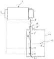
- the shown liquid supply system comprises a metering pump 2 having a control device 4 for controlling the operation of the metering pump 2.
- the metering pump 2 is connected to a suction lance 6 via a suction line 8.
- the level sensors 10 and 12 are vertically distanced and the level sensor 10 is provided for generating an empty signal, whereas the higher level sensor 12 is arranged for generating a pre-empty signal.
- the level sensors 10 and 12 are connected to the control device 4 so that the control device 4 can receive and evaluate the sensor signals.
- the suction lance 6 is inserted into a liquid container 14 for supplying a liquid like a chemical which is pumped or sucked by the metering pump 2.
- the liquid container 14 has an opening 16 through which the suction lance 6 is inserted.
- a closing element 18 which is attached to the opening 16 for closing the remaining part of the opening and fixing the suction lance 6 inside the liquid container 14, in particular in vertical direction.
- the lower free end 20 of the suction lance 16 in this position is arranged close to the bottom of the liquid container 14. In this free end 20 the suction lance 6 has a suction opening through which a liquid is sucked and feed to the metering pump 2.
- liquid is sucked out of the liquid container 14 so that the liquid level 22 decreases in the direction of the arrow A.
- the liquid sensor 12 gives a signal to the control device 4 which is the pre-empty signal.
- the control device 4 may signalize to an operator that the liquid container 14 becomes emptied soon. With the further decreasing of the liquid level 22 in direction A the liquid level 22, then, will reach the lower level sensor 10 when the liquid container 14 is emptied or substantially emptied and the signal generated by the level sensor 10 in response can be regarded as an empty signal.
- This signal is transferred to the control device 4 and the control device 4 can for example stop the operation of the metering pump 2 and signalize to an operator that the liquid container 14 has to be exchanged.
- control device 4 is configured such that it has a lance removal detection system. This may be realized by a respective software inside the control device 4.
- the decreasing of the liquid level 22 takes a certain time, i.e. there is a certain time between the upper level sensor 22 falling dry and the lower level sensor 10 falling dry. If the suction lance 6 is removed out of the liquid container 14 in direction of arrow B the upper level sensor 12 will pass the liquid level 22 first and the lower level sensor 10 will pass the liquid level 22 later. This means also when removing the suction lance 6 the upper level sensor 12 falls dry first and the lower level sensor 10 falls dry later.
- the speed when removing the suction lance 6 out of the liquid container 14 is much faster than the speed with which the liquid level 22 decreases during normal operation.
- This means dB/dt is higher than dA/dt.
- the threshold may be ten seconds.
- the time between a dry detection of the upper level sensor 12 and the lower level sensor 10 is below 10 seconds this is regarded as a removal of the lance 6 out of the liquid container 14.
- the control device 4 may be configured such that in response of the lance removal detection it starts an action for example stops the operation of the metering pump 2 or signalizes to an operator that the suction lance 6 has been removed from the liquid container 14. With this, for example a change of the liquid container 14 can be detected. Furthermore, it can be detected if the suction lance 6 is removed from the liquid container 14 to open the opening 16, for example for refilling the liquid container 14. In certain applications if may be undesirable to refill the liquid container 14, for example to ensure a certain quality of the liquid supplied to the metering pump 2. For these solutions the described lance removal detection may be advantageous.
- two level sensors 10 and 12 vertically distanced from one another.
- a floating sensor which may be able to detect different liquid levels 22 and detect a change of the height of the liquid level 22 with a single sensor.
- a floating element may be coupled to a position sensor detecting the vertical position.
Landscapes
- Engineering & Computer Science (AREA)
- Physics & Mathematics (AREA)
- Mechanical Engineering (AREA)
- Fluid Mechanics (AREA)
- General Physics & Mathematics (AREA)
- General Engineering & Computer Science (AREA)
- Thermal Sciences (AREA)
- Electromagnetism (AREA)
- Power Engineering (AREA)
- Acoustics & Sound (AREA)
- Devices For Dispensing Beverages (AREA)
- Measurement Of Levels Of Liquids Or Fluent Solid Materials (AREA)
- Control Of Positive-Displacement Pumps (AREA)
Priority Applications (3)
| Application Number | Priority Date | Filing Date | Title |
|---|---|---|---|
| EP20183132.8A EP3933193A1 (de) | 2020-06-30 | 2020-06-30 | Flüssigkeitszuführsystem |
| US17/357,218 US11661240B2 (en) | 2020-06-30 | 2021-06-24 | Liquid supply system |
| CN202110736472.3A CN113864146B (zh) | 2020-06-30 | 2021-06-30 | 液体供应系统 |
Applications Claiming Priority (1)
| Application Number | Priority Date | Filing Date | Title |
|---|---|---|---|
| EP20183132.8A EP3933193A1 (de) | 2020-06-30 | 2020-06-30 | Flüssigkeitszuführsystem |
Publications (1)
| Publication Number | Publication Date |
|---|---|
| EP3933193A1 true EP3933193A1 (de) | 2022-01-05 |
Family
ID=71409174
Family Applications (1)
| Application Number | Title | Priority Date | Filing Date |
|---|---|---|---|
| EP20183132.8A Pending EP3933193A1 (de) | 2020-06-30 | 2020-06-30 | Flüssigkeitszuführsystem |
Country Status (3)
| Country | Link |
|---|---|
| US (1) | US11661240B2 (de) |
| EP (1) | EP3933193A1 (de) |
| CN (1) | CN113864146B (de) |
Cited By (1)
| Publication number | Priority date | Publication date | Assignee | Title |
|---|---|---|---|---|
| US20210403201A1 (en) * | 2020-06-30 | 2021-12-30 | Grundfos Holding A/S | Liquid supply system |
Families Citing this family (1)
| Publication number | Priority date | Publication date | Assignee | Title |
|---|---|---|---|---|
| US20220135317A1 (en) * | 2020-11-05 | 2022-05-05 | Jana Pulak | System for controlling the supply of water to a rooftop water tank |
Citations (4)
| Publication number | Priority date | Publication date | Assignee | Title |
|---|---|---|---|---|
| US3601285A (en) * | 1969-05-14 | 1971-08-24 | Asa L Leger | Method and system for dispensing metered amounts of fluid substances from bulk containers |
| US20150177742A1 (en) * | 2012-07-04 | 2015-06-25 | Xylem Ip Management S.A.R.L. | Method for controlling a pump station |
| US20190085840A1 (en) * | 2017-09-18 | 2019-03-21 | Jeremy Leonard | Autonomous submersible pump |
| US20190101427A1 (en) * | 2017-09-29 | 2019-04-04 | Elexa Consumer Products, Inc. | Sump pump monitor |
Family Cites Families (2)
| Publication number | Priority date | Publication date | Assignee | Title |
|---|---|---|---|---|
| FR3039862B1 (fr) * | 2015-08-06 | 2017-08-11 | Dosatron International | Dispositif de dosage proportionnel supervise et procedes de supervision d'une pompe doseuse |
| EP3933193A1 (de) * | 2020-06-30 | 2022-01-05 | Grundfos Holding A/S | Flüssigkeitszuführsystem |
-
2020
- 2020-06-30 EP EP20183132.8A patent/EP3933193A1/de active Pending
-
2021
- 2021-06-24 US US17/357,218 patent/US11661240B2/en active Active
- 2021-06-30 CN CN202110736472.3A patent/CN113864146B/zh active Active
Patent Citations (4)
| Publication number | Priority date | Publication date | Assignee | Title |
|---|---|---|---|---|
| US3601285A (en) * | 1969-05-14 | 1971-08-24 | Asa L Leger | Method and system for dispensing metered amounts of fluid substances from bulk containers |
| US20150177742A1 (en) * | 2012-07-04 | 2015-06-25 | Xylem Ip Management S.A.R.L. | Method for controlling a pump station |
| US20190085840A1 (en) * | 2017-09-18 | 2019-03-21 | Jeremy Leonard | Autonomous submersible pump |
| US20190101427A1 (en) * | 2017-09-29 | 2019-04-04 | Elexa Consumer Products, Inc. | Sump pump monitor |
Cited By (2)
| Publication number | Priority date | Publication date | Assignee | Title |
|---|---|---|---|---|
| US20210403201A1 (en) * | 2020-06-30 | 2021-12-30 | Grundfos Holding A/S | Liquid supply system |
| US11661240B2 (en) * | 2020-06-30 | 2023-05-30 | Grundfos Holding A/S | Liquid supply system |
Also Published As
| Publication number | Publication date |
|---|---|
| CN113864146B (zh) | 2023-08-25 |
| US11661240B2 (en) | 2023-05-30 |
| CN113864146A (zh) | 2021-12-31 |
| US20210403201A1 (en) | 2021-12-30 |
Similar Documents
| Publication | Publication Date | Title |
|---|---|---|
| US11661240B2 (en) | Liquid supply system | |
| KR101897572B1 (ko) | 자동추출장치 및 자동추출제어방법 | |
| JP5015655B2 (ja) | 液体材料供給装置およびこれを用いた液体材料供給方法 | |
| EP1533597A1 (de) | Fluidabgabevorrichtung | |
| US4480901A (en) | Arrangement for and a method of processing photosensitive articles | |
| US9709432B2 (en) | Milk level measurement device and related measurement method | |
| JP2001525763A (ja) | 液体を保存容器から補充するシステムおよび方法 | |
| JPS6264912A (ja) | 分注方式 | |
| JPS61125429A (ja) | 薬液分配装置 | |
| US6885306B2 (en) | Capacitive sensing monitor and method therefore | |
| EP2552192B1 (de) | Verfahren zur erkennung eines flusses | |
| JP4765044B2 (ja) | 粘性流体の移送における残量低減方法及びシステム | |
| CN109552818B (zh) | 应用密闭容器用卸压阀的机器和方法 | |
| US20110162681A1 (en) | Transfer conveyor fitted with an automatic container washing system | |
| WO2017128570A1 (zh) | 在线监测系统 | |
| EP0900345B1 (de) | Füllkontrollvorrichtung | |
| JP4814482B2 (ja) | 燃料供給装置 | |
| EP0745832A1 (de) | Vorrichtung zur volumetrischen Abgabe von Flüssigkeiten | |
| US10632494B2 (en) | Adaptive hot melt feed | |
| KR101624847B1 (ko) | 영상을 이용한 유량계측시스템 | |
| JPH062957Y2 (ja) | 充填量制御装置 | |
| CN114007988A (zh) | 用于管理液体废物的系统和方法 | |
| JP3961264B2 (ja) | 内蓋付きタンクの管理装置及び管理方法 | |
| JP2005180240A (ja) | 液体供給システム、センサーユニットおよび液体供給方法 | |
| JP2001240187A (ja) | 液状物質の管理システム及び方法 |
Legal Events
| Date | Code | Title | Description |
|---|---|---|---|
| PUAI | Public reference made under article 153(3) epc to a published international application that has entered the european phase |
Free format text: ORIGINAL CODE: 0009012 |
|
| STAA | Information on the status of an ep patent application or granted ep patent |
Free format text: STATUS: THE APPLICATION HAS BEEN PUBLISHED |
|
| AK | Designated contracting states |
Kind code of ref document: A1 Designated state(s): AL AT BE BG CH CY CZ DE DK EE ES FI FR GB GR HR HU IE IS IT LI LT LU LV MC MK MT NL NO PL PT RO RS SE SI SK SM TR |
|
| B565 | Issuance of search results under rule 164(2) epc |
Effective date: 20200918 |
|
| STAA | Information on the status of an ep patent application or granted ep patent |
Free format text: STATUS: REQUEST FOR EXAMINATION WAS MADE |
|
| 17P | Request for examination filed |
Effective date: 20220630 |
|
| RBV | Designated contracting states (corrected) |
Designated state(s): AL AT BE BG CH CY CZ DE DK EE ES FI FR GB GR HR HU IE IS IT LI LT LU LV MC MK MT NL NO PL PT RO RS SE SI SK SM TR |
|
| STAA | Information on the status of an ep patent application or granted ep patent |
Free format text: STATUS: EXAMINATION IS IN PROGRESS |
|
| 17Q | First examination report despatched |
Effective date: 20231107 |