EP3932756B1 - Vehicle travel control method and vehicle travel control device - Google Patents
Vehicle travel control method and vehicle travel control device Download PDFInfo
- Publication number
- EP3932756B1 EP3932756B1 EP19917538.1A EP19917538A EP3932756B1 EP 3932756 B1 EP3932756 B1 EP 3932756B1 EP 19917538 A EP19917538 A EP 19917538A EP 3932756 B1 EP3932756 B1 EP 3932756B1
- Authority
- EP
- European Patent Office
- Prior art keywords
- vehicle
- deceleration
- subject vehicle
- travel control
- subject
- Prior art date
- Legal status (The legal status is an assumption and is not a legal conclusion. Google has not performed a legal analysis and makes no representation as to the accuracy of the status listed.)
- Active
Links
Images




Classifications
-
- B—PERFORMING OPERATIONS; TRANSPORTING
- B60—VEHICLES IN GENERAL
- B60T—VEHICLE BRAKE CONTROL SYSTEMS OR PARTS THEREOF; BRAKE CONTROL SYSTEMS OR PARTS THEREOF, IN GENERAL; ARRANGEMENT OF BRAKING ELEMENTS ON VEHICLES IN GENERAL; PORTABLE DEVICES FOR PREVENTING UNWANTED MOVEMENT OF VEHICLES; VEHICLE MODIFICATIONS TO FACILITATE COOLING OF BRAKES
- B60T7/00—Brake-action initiating means
- B60T7/12—Brake-action initiating means for automatic initiation; for initiation not subject to will of driver or passenger
- B60T7/22—Brake-action initiating means for automatic initiation; for initiation not subject to will of driver or passenger initiated by contact of vehicle, e.g. bumper, with an external object, e.g. another vehicle, or by means of contactless obstacle detectors mounted on the vehicle
-
- B—PERFORMING OPERATIONS; TRANSPORTING
- B60—VEHICLES IN GENERAL
- B60W—CONJOINT CONTROL OF VEHICLE SUB-UNITS OF DIFFERENT TYPE OR DIFFERENT FUNCTION; CONTROL SYSTEMS SPECIALLY ADAPTED FOR HYBRID VEHICLES; ROAD VEHICLE DRIVE CONTROL SYSTEMS FOR PURPOSES NOT RELATED TO THE CONTROL OF A PARTICULAR SUB-UNIT
- B60W60/00—Drive control systems specially adapted for autonomous road vehicles
- B60W60/001—Planning or execution of driving tasks
- B60W60/0015—Planning or execution of driving tasks specially adapted for safety
-
- B—PERFORMING OPERATIONS; TRANSPORTING
- B60—VEHICLES IN GENERAL
- B60T—VEHICLE BRAKE CONTROL SYSTEMS OR PARTS THEREOF; BRAKE CONTROL SYSTEMS OR PARTS THEREOF, IN GENERAL; ARRANGEMENT OF BRAKING ELEMENTS ON VEHICLES IN GENERAL; PORTABLE DEVICES FOR PREVENTING UNWANTED MOVEMENT OF VEHICLES; VEHICLE MODIFICATIONS TO FACILITATE COOLING OF BRAKES
- B60T7/00—Brake-action initiating means
- B60T7/12—Brake-action initiating means for automatic initiation; for initiation not subject to will of driver or passenger
- B60T7/16—Brake-action initiating means for automatic initiation; for initiation not subject to will of driver or passenger operated by remote control, i.e. initiating means not mounted on vehicle
- B60T7/18—Brake-action initiating means for automatic initiation; for initiation not subject to will of driver or passenger operated by remote control, i.e. initiating means not mounted on vehicle operated by wayside apparatus
-
- B—PERFORMING OPERATIONS; TRANSPORTING
- B60—VEHICLES IN GENERAL
- B60W—CONJOINT CONTROL OF VEHICLE SUB-UNITS OF DIFFERENT TYPE OR DIFFERENT FUNCTION; CONTROL SYSTEMS SPECIALLY ADAPTED FOR HYBRID VEHICLES; ROAD VEHICLE DRIVE CONTROL SYSTEMS FOR PURPOSES NOT RELATED TO THE CONTROL OF A PARTICULAR SUB-UNIT
- B60W10/00—Conjoint control of vehicle sub-units of different type or different function
- B60W10/18—Conjoint control of vehicle sub-units of different type or different function including control of braking systems
-
- B—PERFORMING OPERATIONS; TRANSPORTING
- B60—VEHICLES IN GENERAL
- B60W—CONJOINT CONTROL OF VEHICLE SUB-UNITS OF DIFFERENT TYPE OR DIFFERENT FUNCTION; CONTROL SYSTEMS SPECIALLY ADAPTED FOR HYBRID VEHICLES; ROAD VEHICLE DRIVE CONTROL SYSTEMS FOR PURPOSES NOT RELATED TO THE CONTROL OF A PARTICULAR SUB-UNIT
- B60W10/00—Conjoint control of vehicle sub-units of different type or different function
- B60W10/20—Conjoint control of vehicle sub-units of different type or different function including control of steering systems
-
- B—PERFORMING OPERATIONS; TRANSPORTING
- B60—VEHICLES IN GENERAL
- B60W—CONJOINT CONTROL OF VEHICLE SUB-UNITS OF DIFFERENT TYPE OR DIFFERENT FUNCTION; CONTROL SYSTEMS SPECIALLY ADAPTED FOR HYBRID VEHICLES; ROAD VEHICLE DRIVE CONTROL SYSTEMS FOR PURPOSES NOT RELATED TO THE CONTROL OF A PARTICULAR SUB-UNIT
- B60W30/00—Purposes of road vehicle drive control systems not related to the control of a particular sub-unit, e.g. of systems using conjoint control of vehicle sub-units
- B60W30/08—Active safety systems predicting or avoiding probable or impending collision or attempting to minimise its consequences
- B60W30/095—Predicting travel path or likelihood of collision
- B60W30/0956—Predicting travel path or likelihood of collision the prediction being responsive to traffic or environmental parameters
-
- B—PERFORMING OPERATIONS; TRANSPORTING
- B60—VEHICLES IN GENERAL
- B60W—CONJOINT CONTROL OF VEHICLE SUB-UNITS OF DIFFERENT TYPE OR DIFFERENT FUNCTION; CONTROL SYSTEMS SPECIALLY ADAPTED FOR HYBRID VEHICLES; ROAD VEHICLE DRIVE CONTROL SYSTEMS FOR PURPOSES NOT RELATED TO THE CONTROL OF A PARTICULAR SUB-UNIT
- B60W60/00—Drive control systems specially adapted for autonomous road vehicles
- B60W60/001—Planning or execution of driving tasks
- B60W60/0027—Planning or execution of driving tasks using trajectory prediction for other traffic participants
-
- B—PERFORMING OPERATIONS; TRANSPORTING
- B60—VEHICLES IN GENERAL
- B60T—VEHICLE BRAKE CONTROL SYSTEMS OR PARTS THEREOF; BRAKE CONTROL SYSTEMS OR PARTS THEREOF, IN GENERAL; ARRANGEMENT OF BRAKING ELEMENTS ON VEHICLES IN GENERAL; PORTABLE DEVICES FOR PREVENTING UNWANTED MOVEMENT OF VEHICLES; VEHICLE MODIFICATIONS TO FACILITATE COOLING OF BRAKES
- B60T2201/00—Particular use of vehicle brake systems; Special systems using also the brakes; Special software modules within the brake system controller
- B60T2201/08—Lane monitoring; Lane Keeping Systems
-
- B—PERFORMING OPERATIONS; TRANSPORTING
- B60—VEHICLES IN GENERAL
- B60W—CONJOINT CONTROL OF VEHICLE SUB-UNITS OF DIFFERENT TYPE OR DIFFERENT FUNCTION; CONTROL SYSTEMS SPECIALLY ADAPTED FOR HYBRID VEHICLES; ROAD VEHICLE DRIVE CONTROL SYSTEMS FOR PURPOSES NOT RELATED TO THE CONTROL OF A PARTICULAR SUB-UNIT
- B60W2520/00—Input parameters relating to overall vehicle dynamics
- B60W2520/10—Longitudinal speed
-
- B—PERFORMING OPERATIONS; TRANSPORTING
- B60—VEHICLES IN GENERAL
- B60W—CONJOINT CONTROL OF VEHICLE SUB-UNITS OF DIFFERENT TYPE OR DIFFERENT FUNCTION; CONTROL SYSTEMS SPECIALLY ADAPTED FOR HYBRID VEHICLES; ROAD VEHICLE DRIVE CONTROL SYSTEMS FOR PURPOSES NOT RELATED TO THE CONTROL OF A PARTICULAR SUB-UNIT
- B60W2554/00—Input parameters relating to objects
- B60W2554/40—Dynamic objects, e.g. animals, windblown objects
- B60W2554/404—Characteristics
- B60W2554/4041—Position
-
- B—PERFORMING OPERATIONS; TRANSPORTING
- B60—VEHICLES IN GENERAL
- B60W—CONJOINT CONTROL OF VEHICLE SUB-UNITS OF DIFFERENT TYPE OR DIFFERENT FUNCTION; CONTROL SYSTEMS SPECIALLY ADAPTED FOR HYBRID VEHICLES; ROAD VEHICLE DRIVE CONTROL SYSTEMS FOR PURPOSES NOT RELATED TO THE CONTROL OF A PARTICULAR SUB-UNIT
- B60W2554/00—Input parameters relating to objects
- B60W2554/40—Dynamic objects, e.g. animals, windblown objects
- B60W2554/404—Characteristics
- B60W2554/4045—Intention, e.g. lane change or imminent movement
-
- B—PERFORMING OPERATIONS; TRANSPORTING
- B60—VEHICLES IN GENERAL
- B60W—CONJOINT CONTROL OF VEHICLE SUB-UNITS OF DIFFERENT TYPE OR DIFFERENT FUNCTION; CONTROL SYSTEMS SPECIALLY ADAPTED FOR HYBRID VEHICLES; ROAD VEHICLE DRIVE CONTROL SYSTEMS FOR PURPOSES NOT RELATED TO THE CONTROL OF A PARTICULAR SUB-UNIT
- B60W2554/00—Input parameters relating to objects
- B60W2554/80—Spatial relation or speed relative to objects
-
- B—PERFORMING OPERATIONS; TRANSPORTING
- B60—VEHICLES IN GENERAL
- B60W—CONJOINT CONTROL OF VEHICLE SUB-UNITS OF DIFFERENT TYPE OR DIFFERENT FUNCTION; CONTROL SYSTEMS SPECIALLY ADAPTED FOR HYBRID VEHICLES; ROAD VEHICLE DRIVE CONTROL SYSTEMS FOR PURPOSES NOT RELATED TO THE CONTROL OF A PARTICULAR SUB-UNIT
- B60W2720/00—Output or target parameters relating to overall vehicle dynamics
- B60W2720/10—Longitudinal speed
- B60W2720/103—Speed profile
Definitions
- the present invention relates to a travel control method and a travel control device of a vehicle.
- a device for predicting a route of a vehicle in which when an oncoming vehicle (a vehicle traveling toward a subject vehicle from ahead of the subject vehicle) travelling in an opposite lane of a subject vehicle overpasses a preceding vehicle of the oncoming vehicle, at a situation in which the oncoming vehicle strays from the opposite lane onto a subject lane, whether the oncoming vehicle overtakes the preceding vehicle is determined, and when it is determined that the oncoming vehicle overtakes the preceding vehicle.
- a realization probability is calculated so that the realization probability represents a probability of a route in which a vehicle travels across a lane to an opposite lane side being realized relatively higher than the realization probability calculated when it is determined that the oncoming vehicle does not overtake the preceding vehicle (Patent Document 1).
- Patent Application DE 10 2004 057060 A1 relates to travel assistance by means of adaptive cruise control (ACC) and detection of oncoming vehicles that changes lane to overtake a preceding vehicle, and hence approaches a first vehicle in the opposite direction.
- ACC adaptive cruise control
- a collision time is predicted for a collision between the first and oncoming vehicle having a relative distance. If the collision time is lower than a minimal time and/or the relative distance being smaller than a minimal relative distance, the first vehicle is decelerated which is repeated if the oncoming vehicle is still on the first vehicle's lane.
- Patent Application EP 1 749 687 A1 relates to automatic collision avoidance between a first vehicle traveling on a lane and oncoming vehicle(s) approaching the first vehicle on its lane. Sensors of the first vehicle detect closing velocities and positions of oncoming vehicles, and it is assessed whether a collision between the first and oncoming vehicle occurs. If yes, brakes of the first vehicle are automatically activated to decelerate the first vehicle, whereby the first vehicle may be decelerated at a rate varying between a predefined range.
- Patent Application US 2002/023793 A1 relates to cruise control of a vehicle running on a lane, in which vehicle brakes are activated to decelerate the vehicle when the same-lane probability is high. Specifically, a first vehicle detects whether a preceding vehicle exists within a preset area and whether it is on the same or opposite lane. Further, the first vehicle determines whether the detected preceding vehicle moves or stands, based on information of the first vehicle speed and the relative distance between the first and preceding vehicle. When the relative distance is lower than a predefined value, the first vehicle decelerates.
- the conventional device for predicting the route of the vehicle has functions for generating a plurality of routes that can be adopted by the subject vehicle on a basis of subject vehicle data.
- the plurality of possible routes include a condition in which the subject vehicle decelerates or stops in order to wait for completion of overtake by an overtaking vehicle when a following vehicle overtakes its preceding vehicle in the opposite lane.
- the problem to be solved by the present invention is to provide the travel control method and the travel control device for a vehicle that can suppress discomfort of the occupant in the scene in which the subject vehicle and the oncoming vehicle pass each other.
- the present invention solves the problem mentioned above by setting initial deceleration of the subject vehicle in a case of time until the subject vehicle and the oncoming vehicle pass each other being relatively long to a smaller value than the initial deceleration in a case of the time being relatively short, when it is predicted that the oncoming vehicle travelling in the opposite lane of the travel lane in which the subject vehicle travels enters into the travel lane in which the subject vehicle travels; and executing deceleration travel control of the subject vehicle.
- the deceleration travel control is performed with the relatively small deceleration initially. This allows to secure long grace time for determining whether to stop or reaccelerate the subject vehicle. As a result, the jerk can be decreased when it is determined that reacceleration is performed, and the discomfort of the occupant can be suppressed.
- Fig. 1 is the block diagram illustrating features of the travel control device for a vehicle VTC according to the present embodiment.
- the travel control device is also referred to as a Vehicle Travel Controller (VTC).
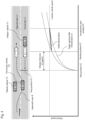
- Figs. 3 to 7 are plan views illustrating examples of the passing scenes, and graphs illustrating deceleration profiles corresponding to the scenes.
- the travel control device for a vehicle VTC of the present embodiment is also an embodiment of implementing the travel control method for a vehicle according to the present invention. As shown in Fig.
- the travel control device for a vehicle VTC of the present embodiment includes a radar device 11, a camera 12, a map database 13, a position detecting device 14, a vehicle speed sensor 15, an oncoming vehicle route predicting unit 21, a subject vehicle route predicting unit 22, a travelability determination unit 23, a target vehicle speed generating unit 24, and a vehicle speed track control unit 25.
- the drive control device 51, the engine 52, the brake control device 53 and the brake 54 are components of the vehicle.
- the terms of the subject vehicle V1, the oncoming vehicle V2, a parked vehicle V3, the travel lane L1, the opposite lane L2, a current position P1 of the subject vehicle V1, a stop position P2 of the subject vehicle V1, a passing position P3, a deceleration start position P4, and an approach route R of the oncoming vehicle V2 are related to the travel scenes as shown in Figs. 3 to 7 . The terms are explained below.
- the radar device 11, the camera 12, the position detecting device 14, and the vehicle speed sensor 15 are composed of various sensors as described later.
- the map database 13 is composed of memories.
- the oncoming vehicle route predicting unit 21, the subject vehicle route predicting unit 22, the travelability determination unit 23, the target vehicle speed generating unit 24, and the vehicle speed track control unit 25 are composed of one or more computers, and software installed in the computers.
- the computer comprises a ROM storing a program for having the respective units such as the oncoming vehicle route predicting unit 21, the subject vehicle route predicting unit 22, the travelability determination unit 23, the target vehicle speed generating unit 24, and the vehicle speed track control unit 25 to function, a CPU executing the program stored in the ROM, and a RAM functioning as an accessible storage device.
- a ROM storing a program for having the respective units such as the oncoming vehicle route predicting unit 21, the subject vehicle route predicting unit 22, the travelability determination unit 23, the target vehicle speed generating unit 24, and the vehicle speed track control unit 25 to function
- a CPU executing the program stored in the ROM
- RAM functioning as an accessible storage device.
- an MPU, a DSP, an ASIC, an FPGA, and the like can be used instead of or together with the CPU.
- the radar device 11 comprises a laser range finder (LRF) provided at a front portion of the vehicle and/or a radar using a millimeter wave or an ultrasonic wave.
- LRF laser range finder
- the radar device 11 outputs information signal on a target or an obstacle to the oncoming vehicle route predicting unit 21.
- the laser range finder irradiates a laser beam, which is an output wave for measuring a distance, to an area in front of the vehicle, and detects the reflected wave (detection wave). This generates a ranging signal indicating the target around the vehicle and a relative position between the target and the vehicle.
- the target is, for example, another vehicle travelling in a travelable road in which the vehicle travels, a motorcycle, a bicycle, a pedestrian, a lane segment line on a road surface, a curb at a shoulder of a road, a guardrail, a wall-surface, a fill, and the like.
- the radar using the millimeter or ultrasonic wave irradiates the millimeter wave or the ultrasonic wave in front of the vehicle to scan a predetermined area around the subject vehicle. This allows to detect the obstacle such as the other vehicle, the motorcycle, the bicycle, the pedestrian, the curb of the shoulder of the road, the guardrail, the wall-surface, and the fill that exist around the subject vehicle.
- the radar device detects the relative position (an azimuth direction) between the obstacle and the subject vehicle, the relative speed of the obstacle, the distance between the subject vehicle and the obstacle, and the like as a situation around the subject vehicle.
- the camera 12 is provided in front of the vehicle, rear of the vehicle and side of the vehicle (i.e., an entire circumference of the vehicle), and outputs the information signal of the target and the obstacle to the oncoming vehicle route predicting unit 21 and the subject vehicle route predicting unit 22.
- the camera 12 is an image sensor for acquiring image data by capturing a predetermined area of the front, the rear, or the side of the subject vehicle, and includes, for example, a CCD wide-angle camera provided in an upper portion of a front windshield within a vehicle cabin, in left-side and right-side mirrors, in a trunk lid, and the like.
- the camera 12 may be a stereoscopic camera or an omnidirectional camera and may include a plurality of the image sensors.
- the camera 12 detects a road existing ahead of, behind, or in sides of the subject vehicle and a structure, a road sign, a signage, the other vehicle, the motorcycle, the bicycle, the pedestrian, and the like as the situation around the subject vehicle from the acquired image data.
- the map database 13 stores three-dimensional high-definition map information.
- the map database 13 is a memory accessible from the oncoming vehicle route predicting unit 21 and the subject vehicle route predicting unit 22.
- the three-dimensional high-definition map information stored in the map database 13 is three-dimensional map information based on a road shape detected when a vehicle for acquiring data travels on the road actually.
- the three-dimensional high-definition map information is map information to which, together with the map information, detailed and high-definition positional information such as a merge point of the road, a branch point, a tollgate, a position at which the number of lanes decreases, a service area, a parking area and the like are related as three-dimensional information.
- the position detecting device 14 comprises a GPS unit, a gyro sensor, and a vehicle speed sensor, and the like.
- the position detecting device 14 detects radio waves transmitted from a plurality of satellite communications by the GPS unit and periodically acquires positional information of the subject vehicle.
- the position detecting device 14 detects the current positional information of the subject vehicle on a basis of the acquired positional information of the subject vehicle, angle change information acquired from the gyro sensor, and vehicle speed acquired from the vehicle speed sensor.
- the detected positional information of the subject vehicle is output to the oncoming vehicle route predicting unit 21 and the subject vehicle route predicting unit 22.
- the vehicle speed sensor 15 measures rotational speed of a drivetrain of the vehicle, such as a drive shaft, and detects travel speed of the subject vehicle on a basis of the measurement result.
- the travel speed is also referred to as "vehicle speed”.
- the vehicle speed information of the subject vehicle detected by the vehicle speed sensor 15 is output to the subject vehicle route predicting unit 22 and the target vehicle speed generating unit 24.
- the oncoming vehicle route predicting unit 21 acquires a distance between the subject vehicle and a target around the subject vehicle output from the radar device 11 and the image data around the subject vehicle output from the camera 12 at a predetermined time interval. Thus, the oncoming vehicle route predicting unit 21 detects whether the other vehicle exists around the subject vehicle. In addition, the oncoming vehicle route predicting unit 21 detects whether the detected other vehicle is the oncoming vehicle travelling in the opposite lane of the travel lane in which the subject vehicle travels. When the detected other vehicle is the oncoming vehicle, it is predicted whether the oncoming vehicle enters into the travel lane in which the subject vehicle travels. And when it is predicted that the oncoming vehicle enters into the travel lane in which the subject vehicle travels, an approach route R of the oncoming vehicle is predicted.
- the oncoming vehicle route predicting unit 21 of the travel control device VTC mounted on the subject vehicle V1 detects the existence of the oncoming vehicle V2 and the parked vehicle V3 from the information signal from the radar device 11 and the camera 12.
- the oncoming vehicle route predicting unit 21 recognizes the road information around the subject vehicle V1 by the information signal from the map database 13 and the position detecting device 14.
- the oncoming vehicle route predicting unit 21 recognizes that the subject vehicle V1 travels in the travel lane L1, the oncoming vehicle V2 travels in the opposite lane L2 toward the subject vehicle V1, and the parked vehicle V3 is parked on the opposite lane L2 ahead of the oncoming vehicle V2.
- the oncoming vehicle route predicting unit 21 detects the vehicle speed of the subject vehicle V1, the vehicle speed of the oncoming vehicle V2, the vehicle speed of the parked vehicle V3, the distance between the subject vehicle V1 and the oncoming vehicle V2, the distance between the subject vehicle V1 and the parked vehicle V3, and a trajectory of the oncoming vehicle V2.
- the trajectory of the oncoming vehicle V2 is a temporal change of the position of the oncoming vehicle V2.
- the oncoming vehicle V2 is not limited to the vehicle traveling on the opposite lane L2, and includes the vehicle traveling toward the subject vehicle while straying from the opposite lane L2.
- the oncoming vehicle route predicting unit 21 detects whether the other vehicles V2, V3 exist around the subject vehicle V1. Next, it is detected whether the detected other vehicles V2, V3 are the oncoming vehicle V2 that travels in the opposite lane L2 of the travel lane L1 in which the subject vehicle V1 travels. When the detected other vehicles V2, V3 are the oncoming vehicle V2, it is predicted whether the oncoming vehicle V2 enters into the travel lane L1 in which the subject vehicle V1 travels. When the oncoming vehicle V2 is predicted to enter into the travel lane L1 in which the subject vehicle V1 travels, such as to avoid the parked vehicle V3, the approach route R is also predicted.
- whether the oncoming vehicle V2 enters into the travel lane L1 in which the subject vehicle V1 travels can be predicted on a basis of conditions such as whether the trajectory of the oncoming vehicle V2 heads to the travel lane L1 in which the subject vehicle V1 travels, the trajectory of the oncoming vehicle V2 being determined by temporal change of the position of the oncoming vehicle V2, or whether the parked vehicle V3 exists in the opposite lane L2, whether the oncoming vehicle V2 is sufficiently close to the parked vehicle V3 as compared to the distance between the subject vehicle V1 and the parked vehicle V3, and whether the oncoming vehicle V2 is in the situation to be able to overtake the parked vehicle V3 with sufficient time.
- the approach route R of the oncoming vehicle V2 can be predicted on a basis of conditions of the position and the vehicle speed of the oncoming vehicle V2, the road shape of the opposite lane L2 and the travel lane L1, and the position and the shape (size) of the parked vehicle V3.
- the oncoming vehicle route predicting unit 21 acquires the current position, the vehicle speed, and the approach route R of the oncoming vehicle V2 entering into the travel lane L1 in which the subject vehicle V1 travels.
- the oncoming vehicle route predicting unit 21 outputs these information signals to the travelability determination unit 23 at the predetermined time interval.
- the current position, the vehicle speed, and the approach route R of the oncoming vehicle V2 entering into the travel lane L1 in which the subject vehicle V1 travels change from time to time as travel time of the subject vehicle V1 elapses. Therefore, the oncoming vehicle route predicting unit 21 repeats the calculation at the predetermined time interval, and outputs them to the travelability determination unit 23.
- the subject vehicle route predicting unit 22 generates a travel route corresponding to the destination that is input in advance by the driver.
- the subject vehicle route predicting unit 22 recognizes the current position of the subject vehicle V1 by the information signal from the position detecting device 14 in order to drive the subject vehicle V1 along the travel route.
- the subject vehicle route predicting unit 22 recognizes the travel lane L1 of the subject vehicle V1 by the information signal from the map database 13. Further, the subject vehicle route predicting unit 22 recognizes the vehicle speed of the subject vehicle V1 by the information signal from the vehicle speed sensor 15. Then, the subject vehicle route predicting unit 22 acquires the information signal on the target and the obstacle around the subject vehicle V1 from the camera 12 at the predetermined time interval. As a result, the subject vehicle V1 travels along the travel lane L1.
- the subject vehicle route predicting unit 22 executes speed control corresponding to the target such as a traffic light, a pedestrian crossing, or a stop sign when they are detected.
- the speed control or trajectory control is executed to avoid the contact with the obstacle.
- the subject vehicle route predicting unit 22 determines the travel route, the current position, and the vehicle speed of the subject vehicle V1 as described above. Then, the subject vehicle route predicting unit 22 outputs these information signals to the travelability determination unit 23 at the predetermined time interval.
- the travel route, the current position, and the vehicle speed of the subject vehicle V1 change from time to time as the travel time of the subject vehicle V1 elapses. Therefore, the subject vehicle route predicting unit 22 repeats the calculation at the predetermined time interval, and outputs them to the travelability determination unit 23.
- the travelability determination unit 23 determines whether the subject vehicle V1 comes into contact with the oncoming vehicle V2 when the subject vehicle V1 travels at the current speed without the deceleration. That is, the travelability determination unit 23 determines whether the subject vehicle V1 and the oncoming vehicle V2 can pass each other without coming into contact with each other in the travel scene as shown in Fig. 3 , on a basis of the current position, the vehicle speed and the approach route R of the oncoming vehicle V2 output from the oncoming vehicle route predicting unit 21 and the travel route, the current position and the vehicle speed of the subject vehicle V1 output from the subject vehicle route predicting unit 22.
- the travelability determination unit 23 sets the stop position P2 of the subject vehicle V1 from the approach route R of the oncoming vehicle V2.
- the approach route R of the oncoming vehicle V2 is predicted by the oncoming vehicle route predicting unit 21.
- the stop position of the subject vehicle V1 that does not come into contact with the oncoming vehicle V2 traveling along the approach route R is set.
- the position before the oncoming vehicle V2 changes lanes to return from the travel lane L1 into which the oncoming vehicle V2 entered to the original opposite lane L2 is set to the stop position P2 of the subject vehicle V1.
- the stop position P2 can be set only by the approach route R of the oncoming vehicle V2 regardless of the current position or the vehicle speed of the subject vehicle V1. Alternatively, the stop position P2 may be set to the position predetermined distance away from the parked vehicle V3 on a basis of, for example, the position of the parked vehicle V3 of the opposite lane L2.
- the encounter position is the position at which the subject vehicle V1 travels from the current position P1 by L ⁇ v1/(v1+v2).
- the information signal of "passable" is output to the target vehicle speed generating unit 24, and the previous speed control is continued.
- the travelability determination unit 23 executes the deceleration control when it is determined that the subject vehicle V1 comes into contact with the oncoming vehicle V2 when the subject vehicle V1 travels at the current speed without the deceleration.
- the travelability determination unit 23 sets the target vehicle speed profile for controlling the travel with the predetermined reference deceleration ⁇ in order to execute the deceleration control for stopping the subject vehicle V1 at the stop position P2.
- the travelability determination unit 23 calculates the passing position P3 at which the subject vehicle V1 and the oncoming vehicle V2 pass each other on a basis of the target vehicle speed profile and the vehicle speed of the oncoming vehicle V2.
- the travelability determination unit 23 outputs to the target vehicle speed generating unit 24 at the predetermined time interval whether the subject vehicle V1 and the oncoming vehicle V2 can pass each other, the distance between the current position of the subject vehicle V1 to the stop position, the passing position P3 at which the subject vehicle V1 and the oncoming vehicle V2 pass each other, and the deceleration start position P4.
- the deceleration start position P4 and the passing position P3 can be determined as follows.
- the stop position P2 of the subject vehicle V1 is set on a basis of the approach route R of the oncoming vehicle V2.
- the predetermined reference deceleration ⁇ that can be stop at the stop position P2 is set.
- the ⁇ is set to between 1.0 and 1.4 m/s 2 , the gentler deceleration that does not discomfort the occupant.
- the vehicle speed curve using the ⁇ is shown in Fig. 3 as a parabola of the target speed profile.
- the intersection of the straight line representing the current vehicle speed of the subject vehicle V1 and the parabola of the target speed profile is determined as the deceleration start position P4 of the subject vehicle V1.
- the subject vehicle V1 travels while maintaining the current vehicle speed and starts the deceleration in accordance with the reference deceleration ⁇ of the target speed profile at the deceleration start position P4
- the subject vehicle V1 is decelerated at the speed in accordance with the target speed profile and is stopped at the stop position P2.
- the passing position P3 at which the subject vehicle V1 and the oncoming vehicle V2 pass each other is calculated from the target speed profile and the vehicle speed of the oncoming vehicle V2 at this time.
- the passing position P3 When the passing position P3 is located in the near side (closer to the subject vehicle V1) relative to the stop position P2 as shown in Figs. 3 to 5 , it is determined that at the present time, the subject vehicle V1 can pass by the oncoming vehicle V2 without coming into contact with the oncoming vehicle V2 so long as the subject vehicle V1 travels at the speed in accordance with the target speed profile.
- the passing position P3 when the passing position P3 is located in the far side relative to the stop position P2 as shown in Fig. 6 , it is determined that, at the present time, the subject vehicle V1 comes into contact with the oncoming vehicle V2 even when the subject vehicle V1 travels at the speed in accordance with the target speed profile.
- the travelability determination unit 23 When the passing position P3 is located in the near side relative to the stop position P2 as shown in Figs. 3 to 5 , the travelability determination unit 23 outputs the information signal of "passable when decelerated with the reference deceleration ⁇ " to the target vehicle speed generating unit 24. On the other hand, when the passing position P3 is located in the far side relative to the stop position P2 as shown in Fig. 6 , the information signal of "impassable even when decelerated with the reference deceleration ⁇ " is output to the target vehicle speed generating unit 24.
- the travelability determination unit 23 outputs the distance between the current position to the stop position of the subject vehicle V1, the passing position P3 at which the subject vehicle V1 and the oncoming vehicle V2 pass each other, and the deceleration start position P4 to the target vehicle speed generating unit 24.
- the target vehicle speed generating unit 24 acquires the travelability determination, the deceleration start position P4, the passing position P3, and the distance to the stop position P2 from the travelability determination unit 23, and the vehicle speed of the subject vehicle V1 from the vehicle speed sensor 15 at the predetermined time interval. In addition, the target vehicle speed generating unit 24 calculates and sets initial deceleration at an early stage when the subject vehicle V1 shifts to the deceleration control. Together with this, the target vehicle speed generating unit 24 sets final deceleration from the end point of the deceleration control with the initial deceleration to the point at which the deceleration control finally finishes. Then, the target vehicle speed generating unit 24 outputs the set initial deceleration ⁇ 1 and the set final deceleration ⁇ 2 to the vehicle speed track control unit 25.
- the initial deceleration setting unit 241 calculates the initial deceleration at the early stage when the subject vehicle V1 shifts to the deceleration control.
- the final deceleration setting unit 242 calculates the final deceleration from the end point of the deceleration control with the initial deceleration to the point at which the deceleration control finally finishes. Note that, depending on the travel scene, the initial deceleration may substitute for the final deceleration.
- the target vehicle speed generating unit 24 sets the deceleration profile in which the deceleration between the deceleration start position P4 and the stop position P2 becomes smaller (including that the deceleration is 0) as the time until the subject vehicle V1 passes by the oncoming vehicle V2 becomes longer, compared to the case in which the time to pass each other is shorter.
- the target vehicle speed generating unit 24 executes the deceleration control with the deceleration in accordance with the deceleration profile.
- the initial deceleration ⁇ 1 at the deceleration start position P4 is set to the smaller deceleration than the final deceleration ⁇ 2 immediately before the stop position P2.
- a plurality of different deceleration values is set, and the plurality of the different deceleration values is set smaller as the position of the subject vehicle V1 becomes closer to the deceleration start position P4 (i.e., as the elapsed time since the deceleration starts is shorter).
- the initial deceleration setting unit 241 of the target vehicle speed generating unit 24 sets the initial deceleration ⁇ 1 between the deceleration start position P4 and the point at which the deceleration is switched to the value smaller than the deceleration ⁇ of the target speed profile with respect to the deceleration ⁇ of the target speed profile (i.e., ⁇ is larger than ⁇ 1, and the absolute value of the slope of the graph shown is small).
- the final deceleration setting unit 242 of the target vehicle speed generating unit 24 sets the final deceleration ⁇ 2 between the position at which the deceleration is switched to the stop position P2 larger than the initial deceleration ⁇ 1, and larger than the deceleration ⁇ of the target speed profile (i.e., ⁇ 2 is larger than ⁇ , and ⁇ is larger than ⁇ 1, and the absolute value of the slope of the graph shown is larger).
- the initial deceleration setting unit 241 of the target vehicle speed generating unit 24 can set a fixed value determined in advance as the initial deceleration ⁇ 1 when setting the initial deceleration ⁇ 1.
- the fixed value is, for example, 0 to 0.7 m/s 2 with respect to the reference deceleration of 1.0 to 1.4 m/s 2 .
- the fixed value may be a value corresponding to the distance between the passing position P3 and the stop position P2.
- the travel scenes shown in Fig. 4 and Fig. 5 indicate scenes in which the respective distances between the passing position P3 and the stop position P2 determined by the travelability determination unit 23 are different. The distance between the passing position P3 and the stop position P2 in the travel scene shown in Fig.
- the initial deceleration setting unit 241 of the target vehicle speed generating unit 24 sets the smaller initial deceleration as the distance between the stop position P2 and the passing position P3 is larger ( Fig. 4 ) compared to the case in which the distance between the stop position P2 and the passing position P3 is smaller ( Fig. 5 ).
- the absolute value of the slope of the initial deceleration in Fig. 4 is set to be smaller than the absolute value of the slope of the initial deceleration in Fig. 5 . That the distance between the stop position P2 and the passing position P3 is larger means that the position at which the subject vehicle V1 and the oncoming vehicle V2 pass each other is located in the near side relative to the stop position P2 when decelerated with the reference deceleration. Therefore, it is highly likely that the oncoming vehicle V2 returns to the original opposite lane L2 after the relatively short, elapsed time. Therefore, by setting the small initial deceleration, the subsequent movement of the oncoming vehicle V2 can be observed, and the unnecessary deceleration can be suppressed.
- the initial deceleration ⁇ 1 may comprise a plurality of initial deceleration values ⁇ 11, ⁇ 12, ....
- the last initial deceleration i.e., the initial deceleration just before switching to the final deceleration, is preferably set to the smallest initial deceleration of the plurality of the initial deceleration values. This is because setting the last initial deceleration to the smallest deceleration decreases the jerk when transitioning from the deceleration travel control to the reacceleration travel control.
- the final deceleration setting unit 242 of the target vehicle speed generating unit 24 sets the deceleration with which the subject vehicle V1 can be stopped at the stop position P2 on a basis of the initial deceleration ⁇ 1, the timing of switching from the initial deceleration ⁇ 1, and the distance to the stop position P2.
- the final deceleration ⁇ 2 may be the predetermined fixed value within the deceleration limits at which the occupant is not discomforted.
- the fixed values may be, for example, 1.8 to 2.2 m/s 2 with respect to the reference deceleration 1.0 to 1.4 m/s 2 .
- the final deceleration ⁇ 2 that is the predetermined fixed value is set so that the subject vehicle V1 is stopped at the stop position P2.
- the intersection of the speed profile in accordance with the final deceleration ⁇ 2 and the initial deceleration ⁇ 1 is defined as the switch position (the switch timing) to switch from the initial deceleration ⁇ 1 to the final deceleration ⁇ 2.
- the final deceleration ⁇ 2 may include a plurality of final deceleration values ⁇ 21, ⁇ 22 ....
- the deceleration travel control continues with the final deceleration.
- the final deceleration setting unit 242 prioritizes the stop control of the subject vehicle V1 and resets the final deceleration larger than the predetermined final deceleration.
- the initial deceleration setting unit 241 and the final deceleration setting unit 242 of the target vehicle speed generating unit 24 set the reference deceleration ⁇ to the final deceleration in place of setting the initial deceleration ⁇ 1. It is determined whether the subject vehicle V1 can be stopped at the stop position P2 on a basis of the set final deceleration ⁇ , the current position P1 of the subject vehicle V1, the current vehicle speed of the subject vehicle V1 and the stop position P2.
- the reference deceleration ⁇ is set to the final deceleration ⁇ 2.
- the stop control of the subject vehicle V1 is prioritized, and the final deceleration ⁇ 2 larger than the reference deceleration ⁇ is set.
- the vehicle speed track control unit 25 acquires the initial deceleration ⁇ 1 and the final deceleration ⁇ 2 generated by the initial deceleration setting unit 241 and the final deceleration setting unit 242 of the target vehicle speed generating unit 24.
- the vehicle speed track control unit 25 generates the vehicle speed of the subject vehicle V1 in accordance with the current position of the subject vehicle V1.
- the vehicle speed track control unit 25 outputs the information signal to the drive control device 51 and the brake control device 53 provided in the vehicle controller of the subject vehicle V1.
- the subject vehicle V1 comprises the engine 52 that is drive source, and the brake 54 that is brake source.
- the engine 52 is controlled by the drive control device 51.
- the brake 54 (the brake booster) is controlled by the brake control device 53.
- the vehicle speed signal from the vehicle speed track control unit 25 is input to each of the drive control device 51 and the brake control device 53.
- the acceleration travel control, the constant speed travel control, or the deceleration travel control of the subject vehicle V1 is executed.
- the vehicle of the present invention is not particularly limited.
- the vehicle includes electric vehicles (including fuel-cell vehicles) powered by motors as the drive source, hybrid vehicles comprising both of the engine and the motor, in addition to engine vehicles powered by the gasoline engines or the diesel engines as the drive source.
- the flow charts shown in Fig. 2A and Fig. 2B illustrate the procedure of the process in the passing scene executed by the travel control device VTC shown in Fig. 1 .
- the flow charts are executed at the predetermined time intervals.
- the subject vehicle V1 is assumed to autonomously travel toward the destination by the autonomous travel function.
- the oncoming vehicle route predicting unit 21 of the travel control device VTC detects whether the oncoming vehicle V2 travelling in the opposite lane L2 of the subject vehicle V1 exists by the radar device 11 and the camera 12.
- the oncoming vehicle V2 travelling in the opposite lane L2 exists, in the step S3, it is predicted whether the oncoming vehicle V2 enters into the travel lane L1 in which the subject vehicle V1 travels.
- the process returns to the step S1 and the autonomous travel is continued.
- the oncoming vehicle V2 is detected in the step S2
- the distance between the subject vehicle V1 and the oncoming vehicle V2 may also detected, and when the distance is shorter than the predetermined distance, the deceleration control of the subject vehicle V1 may be executed at the large deceleration corresponding to the emergency brake.
- step S3 when it is predicted that the oncoming vehicle V2 enters into the travel lane L1 in which the subject vehicle V1 travels, the process proceeds to the step S4.
- the travelability determination unit 23 determines whether the subject vehicle V1 can pass by the oncoming vehicle V2 without coming into contact with the oncoming vehicle V2 in the case that the subject vehicle V1 travels at the current vehicle speed, on the basis of the current position of the subject vehicle speed V1, the vehicle speed of the subject vehicle V1, the current position of the oncoming vehicle V2, and the vehicle speed of the oncoming vehicle V2.
- the process proceeds to the step S5.
- step S4 when it is determined that the subject vehicle V1 and the oncoming vehicle V2 can pass each other, the process returns to the step S1, and the autonomous travel is continued.
- step S4 when it is determined that the subject vehicle V1 cannot pass by the oncoming vehicle V2 unless the subject vehicle V1 decelerates, in the step S5, the travelability determination unit 23 acquires the current position of the subject vehicle V1, the vehicle speed of the subject vehicle V1, the current position of the oncoming vehicle V2, and the vehicle speed of the oncoming vehicle V2. Then, in the step S6, the travelability determination unit 23 predicts the approach route R of the oncoming vehicle V2.
- the approach route R of the oncoming vehicle V2 is generated by the oncoming vehicle route predicting unit 21, the approach route R is output to the travelability determination unit 23 in addition to the current position of the subject vehicle V1, the vehicle speed of the subject vehicle V1, the current position of the oncoming vehicle V2, and the vehicle speed of the oncoming vehicle V2.
- the travelability determination unit 23 sets the stop position P2 of the subject vehicle V1 using the approach route R of the oncoming vehicle V2. Subsequently, in the step S8, the travelability determination unit 23 sets the target vehicle speed profile for controlling the travel with the predetermined reference deceleration ⁇ . The travelability determination unit 23 calculates the passing position P3 at which the subject vehicle V1 and the oncoming vehicle V2 pass each other using the target vehicle speed profile and the vehicle speed of the oncoming vehicle V2.
- the stop position P2 of the subject vehicle V1 is set on the basis of the approach route R of the oncoming vehicle V2.
- a bottom (an extreme value) of the parabola shown in Fig. 3 is adjusted to the stop position P2 so that the vehicle speed of the subject vehicle V1 becomes 0 at the stop position P2.
- the parabola assumes that the target speed profile in which the deceleration ⁇ is constant.
- the intersection of the straight line representing the current vehicle speed of the subject vehicle V1 and the parabola of the target speed profile is determined as the deceleration start position P4 of the subject vehicle V1.
- the subject vehicle V1 When the subject vehicle V1 travels while maintaining the current vehicle speed and starts deceleration in accordance with the reference deceleration ⁇ of the target speed profile at the deceleration start position P4, the subject vehicle V1 decreases the speed in accordance with the target speed profile and stops at the stop position P2.
- the passing position P3 at which the subject vehicle V1 and the oncoming vehicle V2 pass each other is calculated using the target speed profile and the vehicle speed of the oncoming vehicle V2 at this time.
- step S10 it is determined whether the passing position P3 is on the near side (the subject vehicle side) or the far side relative to the stop position P2.
- the process proceeds to the step S11.
- the passing position P 3 is on the far side relative to the stop position P2, the process proceeds to the step S16 in Fig. 2B .
- the initial deceleration ⁇ 1 is set in the step 511. That is, the initial deceleration ⁇ 1 at the deceleration start position P4 is set to the smaller deceleration than the final deceleration ⁇ 2 immediately before the stop position P2. In other words, in place of setting the deceleration between the deceleration start position P4 and the stop position P2 constant, a plurality of different deceleration values is set. In addition, the plurality of different deceleration values is set to become smaller with approaching the deceleration start position P4 (i.e., as the elapsed time since the deceleration starts is shorter). Further, as shown in Fig.
- step S12 it is determined whether the current position P1 of the subject vehicle V1 arrives at the deceleration start position P4.
- the deceleration is started as described in the step S13.
- the step S12 is repeated until the current position P1 of the subject vehicle V1 arrives at the deceleration start position P4. Note that, when the subject vehicle it is determined + does not arrive at the deceleration start position P4, the acceleration travel control may be executed, the deceleration travel control may not be executed, the constant speed travel control may be executed, or the subject vehicle may be coasted by lifting a throttle and without stepping the brake.
- the target vehicle speed is output from the vehicle speed track control unit 25 to the drive control device 51 and the brake control device 53.
- the drive control device 51 controls the engine 52
- the brake control device 53 controls the brake 54, so that the process is executed.
- step S14 it is determined whether the subject vehicle V1 can pass by the oncoming vehicle V2 without coming into contact with the oncoming vehicle V2 on the basis of the current position P1 of the subject vehicle V1, the vehicle speed of the subject vehicle V1, the current position of the oncoming vehicle V2, and the vehicle speed of the oncoming vehicle V2. That is, in the step S13, the deceleration of the subject vehicle V1 with the initial deceleration ⁇ 1 starts and the travel situation of the oncoming vehicle V2 and the like after the deceleration is detected. When it is determined that the subject vehicle V1 can pass by the oncoming vehicle V2 without coming into contact with each other, the process proceeds to the step S15.
- Fig. 7 is the diagram illustrating the scene in which the determination is made to proceed from the step S14 to the step S15 at the travelability determination point with respect to the subject vehicle V1 that starts the deceleration from the deceleration start position P4 with the initial deceleration ⁇ 1.
- the subject vehicle V1 returns to the autonomous travel control of the step S1, whereby the return to the set speed is achieved by the reacceleration indicated by the dotted line in Fig. 7 .
- the jerk between the vehicle speed decelerated with the initial deceleration ⁇ 1 and the vehicle speed after the return becomes smaller as the initial deceleration ⁇ 1 is smaller. That is, when decelerating with the deceleration ⁇ indicated in the target speed profile of Fig. 7 , the jerk between the vehicle speed at the travelability determination point and the vehicle speed after the return increases in accordance with the difference of speed as shown in the figure.
- the process proceeds to the step S16.
- the switch position (the switch timing) is calculated from the currently set initial deceleration ⁇ 1 to the next set final deceleration ⁇ 2. At the same time, it is determined whether the subject vehicle arrives at the switch position.
- the final deceleration setting unit 242 of the target vehicle speed generating unit 24 sets the final deceleration ⁇ 2 with which the subject vehicle V1 can be stopped at the stop position P2, on the basis of the initial deceleration ⁇ 1, the switch timing from the initial deceleration ⁇ 1, and the distance to the stop position P2.
- the final deceleration ⁇ 2 that is the predetermined fixed value is set so that the subject vehicle V1 stops at the stop position P2.
- the intersection of the speed profile in accordance with the final deceleration ⁇ 2 and the initial deceleration ⁇ 1 is defined as the switch position (the switch timing) from the initial deceleration ⁇ 1 to the final deceleration ⁇ 2.
- the switch position the switch timing
- the deceleration is switched from the initial deceleration ⁇ 1 to the final deceleration ⁇ 2.
- step S10 of Fig. 2A when the passing position P3 at which the subject vehicle V1 and the oncoming vehicle V2 pass each other is on the far side relative to the stop position P2 as shown in Fig. 6 , the process proceeds from the step S10 to the step S18.
- the deceleration control with the final deceleration ⁇ 2 starts from the deceleration start position P4, as shown in Fig. 6 . This prevents the subject vehicle V1 from coming into contact with the oncoming vehicle V2,
- step S18 the deceleration is switched to the deceleration with the final deceleration ⁇ 2, and the subject vehicle V1 shifts to the travel control for stopping at the stop position P2.
- step S19 it is determined whether the subject vehicle V1 can be stopped at the stop position P2 on the basis of the current position P1 of the subject vehicle V1, the vehicle speed of the subject vehicle V1, and the distance to the stop position P2.
- the process proceeds to the step S21 of Fig. 2C .
- the process proceeds to the step S19.
- the final deceleration ⁇ 2 is set again that is acquired by increasing the value of the currently set final deceleration ⁇ 2. Then, the process returns to the step S18 while executing the deceleration control with the final deceleration ⁇ 2.
- the subject vehicle V1 can be surely stopped at the stop position P2.
- step S21 of Fig. 2C it is determined whether the subject vehicle V1 can pass by the oncoming vehicle V2 without coming into contact with the oncoming vehicle V2 on the basis of the current position P1 of the subject vehicle V1, the vehicle speed of the subject vehicle V1, the current position of the oncoming vehicle V2 and the vehicle speed of the oncoming vehicle V2. That is, in the step S18, the deceleration of the subject vehicle V1 is switched to the deceleration with the final deceleration ⁇ 2, and the subsequent travel situation of the oncoming vehicle V2 is detected. When it is determined that the subject vehicle V1 and the oncoming vehicle V2 can pass each other without coming into contact with each other, the process proceeds to the step S22.
- the deceleration is terminated, and the process returns to the autonomous travel control of the step S1.
- the subject vehicle V1 reaccelerates and returns to the vehicle speed set by the autonomous travel control.
- the target vehicle speed that conforms to the deceleration smaller than the initial deceleration is generated, there is no need to decrease the deceleration in all the sections from the position at which the deceleration control is stopped to the passing position.
- step S21 when it is determined in the step S21 that the subject vehicle V1 cannot pass by the oncoming vehicle V2 without coming into contact with the oncoming vehicle V2, the process proceeds to the step S23.
- step S23 the deceleration with the final deceleration ⁇ 2 is continued until the subject vehicle arrives at the stop position P2.
- the initial deceleration of the subject vehicle V1 in the case of time until the subject vehicle V1 and the oncoming vehicle V2 pass each other being relatively long is set to the smaller value than the initial deceleration in the case of the time being relatively short.
- the subject vehicle V1 is decelerated with the deceleration in accordance with the deceleration profile that is indicated by the thick line in Fig. 3 . This ensures the grace time for making the determination on the travel control of the subject vehicle V1, such as whether to stop or accelerate the subject vehicle V1.
- the travel control of the subject vehicle V1 can be executed in response to the behaviour of the oncoming vehicle V2 in the grace time. Therefore, it is possible to suppress the unnecessary stop or the unnecessary acceleration. As a result, the discomfort of the occupant can be suppressed.
- the travel control device and the travel control method of the present embodiment is effectively applied to the travel scene in which the subject vehicle V1 decelerates in response to the oncoming vehicle V2.
- the deceleration start position P4 is determined at which the deceleration of the subject vehicle V1 starts so that the subject vehicle V1 does not come into contact with the oncoming vehicle V2 entering into the travel lane L1. Then, whether the subject vehicle V1 arrives at the deceleration start position P4 is detected. When the subject vehicle V1 arrives at the deceleration start position P4, the deceleration travel control of the subject vehicle V1 is executed.
- the deceleration travel control may be executed once the subject vehicle V1 arrives at the deceleration start position P4, with the initial deceleration larger than the initial deceleration in the case that the subject vehicle V1 does not arrive at the deceleration start position P4.
- the stop position P2 for stopping the subject vehicle V1 so that the subject vehicle V1 does not come into contact with the oncoming vehicle V2 entering into the travel lane L1 in which the subject vehicle V1 travels is set on the basis of the situation ahead of the subject vehicle V1.
- the deceleration start position P4 for starting the deceleration of the subject vehicle V1 is determined on the basis of the set stop position P2, the current position P1 of the subject vehicle V1, the current vehicle speed of the subject vehicle V1, the predetermined reference deceleration, and the initial deceleration.
- the target vehicle speed profile for decelerating the subject vehicle V1 with the predetermined reference deceleration from the current position P1 may be set
- the passing position P3 at which the subject vehicle V1 and the oncoming vehicle V2 pass each other may be determined on the basis of the target vehicle speed profile and vehicle speed of the oncoming vehicle V2
- the initial deceleration upon executing the deceleration travel control of the subject vehicle V1 may be set on the basis of the relative positional relation between the stop position P2 and the passing position P3.
- the initial deceleration ⁇ 1 in the case of the distance between the stop position P2 and the passing position P3 being relatively large is set smaller than the predetermined reference deceleration ⁇ and smaller than the initial deceleration in the case of the distance between the stop position P2 and the passing position P3 being relatively small.
- the travel control of the subject vehicle V1 can be executed in response to the behaviour of the oncoming vehicle V2 in the grace time. Therefore, it is possible to further suppress the unnecessary stop or the unnecessary acceleration. As a result, the discomfort of the occupant can be further suppressed.
- the deceleration start position P4 ahead of the subject vehicle V1 is determined. Then, whether the subject vehicle V1 arrives at the deceleration start position P4 is detected.
- the deceleration travel control of the subject vehicle V1 is executed. As a result, the long grace time for making the determination on the travel control of the subject vehicle V1 can be secured. At the same time, the subject vehicle V1 can be stopped at the stop position P1 at the optimum time.
- the set initial deceleration ⁇ 1 is switched to the predetermined final deceleration ⁇ 2 at the timing at which the subject vehicle V1 can be stopped at the stop position P2 when the set initial deceleration ⁇ 1 is switched to the predetermined final deceleration ⁇ 2.
- the final deceleration ⁇ 2 is used to the deceleration travel control of the subject vehicle V1.
- the travel control device and the travel control method of the present embodiment when it is determined that the subject vehicle V1 cannot be stopped at the stop position P2 during the period to switch the initial deceleration ⁇ 1 to the predetermined final deceleration ⁇ 2, the final deceleration is switched to the deceleration larger than the predetermined final deceleration ⁇ 2. Then, the deceleration travel control of the subject vehicle V1 is executed. As a result, the long grace time for making the determination on the travel control of the subject vehicle V1 can be secured. At the same time, the subject vehicle V1 can be surely stopped at the stop position P2 even when the travel situation changes.
- the initial deceleration ⁇ 1 is the predetermined value. This enables to set the deceleration that does not discomfort the occupant.
- the initial deceleration ⁇ 1 includes the plurality of initial deceleration values.
- the long grace time for making the determination on the travel control of the subject vehicle V1 can be secured.
- the vehicle speed before and after passing by can be set so that the jerk becomes small.
- the initial deceleration ⁇ 1 includes the plurality of initial deceleration values. Further, the initial deceleration that is set finally in terms of time (i.e., the initial deceleration just before switching to the final deceleration ⁇ 2) is set to the smallest initial deceleration of the plurality of initial deceleration values.
- the long grace time for making the determination on the travel control of the subject vehicle V1 can be secured.
- the jerk at the time of the reacceleration after passing by is decreased.
- the predetermined reference deceleration ⁇ is set to the final deceleration.
- whether the subject vehicle V1 can be stopped at the stop position P2 is determined on the basis of the set final deceleration ⁇ , the current position P1 of the subject vehicle V1, the current vehicle speed of the subject vehicle V1, and the stop position P2.
- the final deceleration is switched to the deceleration larger than the set final deceleration ⁇ .
- the long grace time for making the determination on the travel control of the subject vehicle V1 can be secured.
- the subject vehicle V1 can be surely stopped at the stop position P2 even when the travel situation changes.
- the behaviour of the oncoming vehicle V2 is detected while executing the deceleration travel control of the subject vehicle V1 with the deceleration in accordance with the deceleration profile. Then, it is predicted whether the subject vehicle V1 can travel in the travel lane L1 without coming into contact with the oncoming vehicle V2. When it is predicted that the subject vehicle V1 can travel in the travel lane L1 without coming into contact with the oncoming vehicle V2, the deceleration travel control is stopped, and the target speed is generated in which the deceleration is not performed. As a result, the long grace time for making the determination on the travel control of the subject vehicle V1 can be secured. At the same time, it is possible to smoothly transit to the subsequent travel control, such as executing the reacceleration control.
- the values of the deceleration ⁇ , ⁇ 1, and ⁇ 2 are set to the appropriate values as control factors.
- the vehicle speed corresponding to the deceleration ⁇ , ⁇ 1, and ⁇ 2 may be used as the control factors.
Landscapes
- Engineering & Computer Science (AREA)
- Transportation (AREA)
- Mechanical Engineering (AREA)
- Automation & Control Theory (AREA)
- Human Computer Interaction (AREA)
- Chemical & Material Sciences (AREA)
- Combustion & Propulsion (AREA)
- Control Of Driving Devices And Active Controlling Of Vehicle (AREA)
- Traffic Control Systems (AREA)
- Regulating Braking Force (AREA)
Applications Claiming Priority (1)
| Application Number | Priority Date | Filing Date | Title |
|---|---|---|---|
| PCT/IB2019/000293 WO2020178608A1 (ja) | 2019-03-01 | 2019-03-01 | 車両の走行制御方法及び走行制御装置 |
Publications (3)
| Publication Number | Publication Date |
|---|---|
| EP3932756A1 EP3932756A1 (en) | 2022-01-05 |
| EP3932756A4 EP3932756A4 (en) | 2022-03-30 |
| EP3932756B1 true EP3932756B1 (en) | 2023-06-21 |
Family
ID=72337669
Family Applications (1)
| Application Number | Title | Priority Date | Filing Date |
|---|---|---|---|
| EP19917538.1A Active EP3932756B1 (en) | 2019-03-01 | 2019-03-01 | Vehicle travel control method and vehicle travel control device |
Country Status (5)
| Country | Link |
|---|---|
| US (1) | US11299178B1 (https=) |
| EP (1) | EP3932756B1 (https=) |
| JP (1) | JP7189318B2 (https=) |
| CN (1) | CN113544023B (https=) |
| WO (1) | WO2020178608A1 (https=) |
Families Citing this family (5)
| Publication number | Priority date | Publication date | Assignee | Title |
|---|---|---|---|---|
| JP7500944B2 (ja) * | 2019-10-11 | 2024-06-18 | 株式会社アイシン | 駐車支援装置、駐車支援方法及び駐車支援プログラム |
| EP3967564B1 (en) * | 2020-09-15 | 2024-05-22 | KNORR-BREMSE Systeme für Nutzfahrzeuge GmbH | Method for adjusting the speed of a vehicle |
| CN115214726B (zh) * | 2021-04-19 | 2025-05-13 | 比亚迪股份有限公司 | 车辆停车控制方法及装置 |
| US11840257B2 (en) * | 2022-03-25 | 2023-12-12 | Embark Trucks Inc. | Lane change determination for vehicle on shoulder |
| JP7441258B2 (ja) * | 2022-03-25 | 2024-02-29 | 本田技研工業株式会社 | 制御装置 |
Family Cites Families (13)
| Publication number | Priority date | Publication date | Assignee | Title |
|---|---|---|---|---|
| JP3611028B2 (ja) * | 2000-08-29 | 2005-01-19 | トヨタ自動車株式会社 | 走行制御装置 |
| JP2004299593A (ja) | 2003-03-31 | 2004-10-28 | Nissan Diesel Motor Co Ltd | 車間保持自動制御装置 |
| DE102004057060A1 (de) * | 2004-11-25 | 2006-06-08 | Daimlerchrysler Ag | Fahrassistenzvorrichtung sowie Verfahren zur Erkennung von auf der eigenen Fahrspur entgegenkommenden Fahrzeugen |
| EP1944189B2 (en) | 2005-08-04 | 2020-06-03 | Volvo Car Corporation | Automatic collision management system |
| JP2009023399A (ja) | 2007-07-17 | 2009-02-05 | Toyota Motor Corp | 衝突防止装置 |
| JP5077182B2 (ja) * | 2008-10-14 | 2012-11-21 | トヨタ自動車株式会社 | 車両進路予測装置 |
| JP2013030149A (ja) * | 2011-06-22 | 2013-02-07 | Nissan Motor Co Ltd | 走行制御装置 |
| US9607519B2 (en) | 2011-06-22 | 2017-03-28 | Nissan Motor Co., Ltd. | Vehicle driving control system |
| DE102012215093A1 (de) * | 2012-08-24 | 2014-02-27 | Robert Bosch Gmbh | Fahrerassistenzsystem und Verfahren zum Betreiben des Fahrerassistenzsystems |
| JP6264457B2 (ja) * | 2014-06-25 | 2018-01-24 | 日産自動車株式会社 | 車両制御装置 |
| JP6397248B2 (ja) | 2014-07-29 | 2018-09-26 | 日立オートモティブシステムズ株式会社 | 車両用走行支援装置 |
| JP6497349B2 (ja) * | 2016-04-13 | 2019-04-10 | トヨタ自動車株式会社 | 車両走行制御装置 |
| US10703361B2 (en) * | 2017-06-14 | 2020-07-07 | Toyota Motor Engineering & Manufacturing North America, Inc. | Vehicle collision mitigation |
-
2019
- 2019-03-01 CN CN201980093216.8A patent/CN113544023B/zh active Active
- 2019-03-01 WO PCT/IB2019/000293 patent/WO2020178608A1/ja not_active Ceased
- 2019-03-01 JP JP2021503220A patent/JP7189318B2/ja active Active
- 2019-03-01 US US17/432,319 patent/US11299178B1/en active Active
- 2019-03-01 EP EP19917538.1A patent/EP3932756B1/en active Active
Also Published As
| Publication number | Publication date |
|---|---|
| WO2020178608A1 (ja) | 2020-09-10 |
| JPWO2020178608A1 (https=) | 2020-09-10 |
| US20220089186A1 (en) | 2022-03-24 |
| US11299178B1 (en) | 2022-04-12 |
| CN113544023B (zh) | 2022-08-30 |
| JP7189318B2 (ja) | 2022-12-13 |
| EP3932756A4 (en) | 2022-03-30 |
| CN113544023A (zh) | 2021-10-22 |
| EP3932756A1 (en) | 2022-01-05 |
Similar Documents
| Publication | Publication Date | Title |
|---|---|---|
| JP7207256B2 (ja) | 車両制御システム | |
| US10583833B2 (en) | Vehicle control apparatus, vehicle control method, and vehicle control program | |
| US10017180B2 (en) | Vehicle control apparatus, vehicle control method, and vehicle control program | |
| EP3932756B1 (en) | Vehicle travel control method and vehicle travel control device | |
| JP6645649B2 (ja) | 車両制御装置、車両制御方法、および車両制御プログラム | |
| CN109070887B (zh) | 车辆控制系统、车辆控制方法及存储介质 | |
| CN108698608B (zh) | 车辆控制系统、车辆控制方法及存储介质 | |
| US10543840B2 (en) | Vehicle control system, vehicle control method, and vehicle control program for automatically controlling vehicle based on generated target speed | |
| CN109195845B (zh) | 车辆控制系统、车辆控制方法及存储介质 | |
| US11072331B2 (en) | Vehicle control device, vehicle control method and vehicle control program | |
| CN110770064B (zh) | 驾驶辅助车辆的目标车速生成方法及目标车速生成装置 | |
| US10220847B2 (en) | Vehicle control apparatus, vehicle control method, and vehicle control program | |
| US20190084561A1 (en) | Vehicle control apparatus, vehicle control method, and vehicle control program | |
| US20190155293A1 (en) | Vehicle control system, vehicle control method and vehicle control program | |
| JP7059652B2 (ja) | 車両制御システム | |
| WO2017138513A1 (ja) | 車両制御装置、車両制御方法、および車両制御プログラム | |
| WO2017158731A1 (ja) | 車両制御システム、車両制御方法、および車両制御プログラム | |
| JP2018034709A (ja) | 車両制御装置 | |
| EP4137378B1 (en) | Travel assistance method and travel assistance device | |
| EP3985355A1 (en) | Vehicle travel control method and vehicle travel control device | |
| JP2017081421A (ja) | 車両制御装置、車両制御方法、および車両制御プログラム | |
| EP4349674B1 (en) | Driving control method and driving control device | |
| WO2025057361A1 (ja) | 運転制御方法及び運転制御装置 | |
| RU2774984C1 (ru) | Способ управления движением транспортного средства и устройство управления движением транспортного средства | |
| RU2781021C1 (ru) | Способ управления транспортным средством и устройство управления транспортным средством |
Legal Events
| Date | Code | Title | Description |
|---|---|---|---|
| STAA | Information on the status of an ep patent application or granted ep patent |
Free format text: STATUS: THE INTERNATIONAL PUBLICATION HAS BEEN MADE |
|
| PUAI | Public reference made under article 153(3) epc to a published international application that has entered the european phase |
Free format text: ORIGINAL CODE: 0009012 |
|
| STAA | Information on the status of an ep patent application or granted ep patent |
Free format text: STATUS: REQUEST FOR EXAMINATION WAS MADE |
|
| 17P | Request for examination filed |
Effective date: 20210824 |
|
| AK | Designated contracting states |
Kind code of ref document: A1 Designated state(s): AL AT BE BG CH CY CZ DE DK EE ES FI FR GB GR HR HU IE IS IT LI LT LU LV MC MK MT NL NO PL PT RO RS SE SI SK SM TR |
|
| RAP3 | Party data changed (applicant data changed or rights of an application transferred) |
Owner name: RENAULT S.A.S Owner name: NISSAN MOTOR CO., LTD. |
|
| A4 | Supplementary search report drawn up and despatched |
Effective date: 20220301 |
|
| RIC1 | Information provided on ipc code assigned before grant |
Ipc: B60T 7/12 20060101AFI20220223BHEP |
|
| DAV | Request for validation of the european patent (deleted) | ||
| DAX | Request for extension of the european patent (deleted) | ||
| RAP3 | Party data changed (applicant data changed or rights of an application transferred) |
Owner name: RENAULT S.A.S Owner name: NISSAN MOTOR CO., LTD. |
|
| GRAP | Despatch of communication of intention to grant a patent |
Free format text: ORIGINAL CODE: EPIDOSNIGR1 |
|
| STAA | Information on the status of an ep patent application or granted ep patent |
Free format text: STATUS: GRANT OF PATENT IS INTENDED |
|
| INTG | Intention to grant announced |
Effective date: 20230228 |
|
| GRAS | Grant fee paid |
Free format text: ORIGINAL CODE: EPIDOSNIGR3 |
|
| GRAA | (expected) grant |
Free format text: ORIGINAL CODE: 0009210 |
|
| STAA | Information on the status of an ep patent application or granted ep patent |
Free format text: STATUS: THE PATENT HAS BEEN GRANTED |
|
| AK | Designated contracting states |
Kind code of ref document: B1 Designated state(s): AL AT BE BG CH CY CZ DE DK EE ES FI FR GB GR HR HU IE IS IT LI LT LU LV MC MK MT NL NO PL PT RO RS SE SI SK SM TR |
|
| REG | Reference to a national code |
Ref country code: CH Ref legal event code: EP |
|
| REG | Reference to a national code |
Ref country code: DE Ref legal event code: R096 Ref document number: 602019031522 Country of ref document: DE |
|
| REG | Reference to a national code |
Ref country code: AT Ref legal event code: REF Ref document number: 1580717 Country of ref document: AT Kind code of ref document: T Effective date: 20230715 |
|
| REG | Reference to a national code |
Ref country code: IE Ref legal event code: FG4D |
|
| REG | Reference to a national code |
Ref country code: LT Ref legal event code: MG9D |
|
| REG | Reference to a national code |
Ref country code: NL Ref legal event code: MP Effective date: 20230621 |
|
| PG25 | Lapsed in a contracting state [announced via postgrant information from national office to epo] |
Ref country code: SE Free format text: LAPSE BECAUSE OF FAILURE TO SUBMIT A TRANSLATION OF THE DESCRIPTION OR TO PAY THE FEE WITHIN THE PRESCRIBED TIME-LIMIT Effective date: 20230621 Ref country code: NO Free format text: LAPSE BECAUSE OF FAILURE TO SUBMIT A TRANSLATION OF THE DESCRIPTION OR TO PAY THE FEE WITHIN THE PRESCRIBED TIME-LIMIT Effective date: 20230921 |
|
| REG | Reference to a national code |
Ref country code: AT Ref legal event code: MK05 Ref document number: 1580717 Country of ref document: AT Kind code of ref document: T Effective date: 20230621 |
|
| PG25 | Lapsed in a contracting state [announced via postgrant information from national office to epo] |
Ref country code: RS Free format text: LAPSE BECAUSE OF FAILURE TO SUBMIT A TRANSLATION OF THE DESCRIPTION OR TO PAY THE FEE WITHIN THE PRESCRIBED TIME-LIMIT Effective date: 20230621 Ref country code: NL Free format text: LAPSE BECAUSE OF FAILURE TO SUBMIT A TRANSLATION OF THE DESCRIPTION OR TO PAY THE FEE WITHIN THE PRESCRIBED TIME-LIMIT Effective date: 20230621 Ref country code: LV Free format text: LAPSE BECAUSE OF FAILURE TO SUBMIT A TRANSLATION OF THE DESCRIPTION OR TO PAY THE FEE WITHIN THE PRESCRIBED TIME-LIMIT Effective date: 20230621 Ref country code: LT Free format text: LAPSE BECAUSE OF FAILURE TO SUBMIT A TRANSLATION OF THE DESCRIPTION OR TO PAY THE FEE WITHIN THE PRESCRIBED TIME-LIMIT Effective date: 20230621 Ref country code: HR Free format text: LAPSE BECAUSE OF FAILURE TO SUBMIT A TRANSLATION OF THE DESCRIPTION OR TO PAY THE FEE WITHIN THE PRESCRIBED TIME-LIMIT Effective date: 20230621 Ref country code: GR Free format text: LAPSE BECAUSE OF FAILURE TO SUBMIT A TRANSLATION OF THE DESCRIPTION OR TO PAY THE FEE WITHIN THE PRESCRIBED TIME-LIMIT Effective date: 20230922 |
|
| PG25 | Lapsed in a contracting state [announced via postgrant information from national office to epo] |
Ref country code: FI Free format text: LAPSE BECAUSE OF FAILURE TO SUBMIT A TRANSLATION OF THE DESCRIPTION OR TO PAY THE FEE WITHIN THE PRESCRIBED TIME-LIMIT Effective date: 20230621 |
|
| PG25 | Lapsed in a contracting state [announced via postgrant information from national office to epo] |
Ref country code: SK Free format text: LAPSE BECAUSE OF FAILURE TO SUBMIT A TRANSLATION OF THE DESCRIPTION OR TO PAY THE FEE WITHIN THE PRESCRIBED TIME-LIMIT Effective date: 20230621 |
|
| PG25 | Lapsed in a contracting state [announced via postgrant information from national office to epo] |
Ref country code: ES Free format text: LAPSE BECAUSE OF FAILURE TO SUBMIT A TRANSLATION OF THE DESCRIPTION OR TO PAY THE FEE WITHIN THE PRESCRIBED TIME-LIMIT Effective date: 20230621 |
|
| PG25 | Lapsed in a contracting state [announced via postgrant information from national office to epo] |
Ref country code: IS Free format text: LAPSE BECAUSE OF FAILURE TO SUBMIT A TRANSLATION OF THE DESCRIPTION OR TO PAY THE FEE WITHIN THE PRESCRIBED TIME-LIMIT Effective date: 20231021 |
|
| PG25 | Lapsed in a contracting state [announced via postgrant information from national office to epo] |
Ref country code: SM Free format text: LAPSE BECAUSE OF FAILURE TO SUBMIT A TRANSLATION OF THE DESCRIPTION OR TO PAY THE FEE WITHIN THE PRESCRIBED TIME-LIMIT Effective date: 20230621 Ref country code: SK Free format text: LAPSE BECAUSE OF FAILURE TO SUBMIT A TRANSLATION OF THE DESCRIPTION OR TO PAY THE FEE WITHIN THE PRESCRIBED TIME-LIMIT Effective date: 20230621 Ref country code: RO Free format text: LAPSE BECAUSE OF FAILURE TO SUBMIT A TRANSLATION OF THE DESCRIPTION OR TO PAY THE FEE WITHIN THE PRESCRIBED TIME-LIMIT Effective date: 20230621 Ref country code: PT Free format text: LAPSE BECAUSE OF FAILURE TO SUBMIT A TRANSLATION OF THE DESCRIPTION OR TO PAY THE FEE WITHIN THE PRESCRIBED TIME-LIMIT Effective date: 20231023 Ref country code: IS Free format text: LAPSE BECAUSE OF FAILURE TO SUBMIT A TRANSLATION OF THE DESCRIPTION OR TO PAY THE FEE WITHIN THE PRESCRIBED TIME-LIMIT Effective date: 20231021 Ref country code: ES Free format text: LAPSE BECAUSE OF FAILURE TO SUBMIT A TRANSLATION OF THE DESCRIPTION OR TO PAY THE FEE WITHIN THE PRESCRIBED TIME-LIMIT Effective date: 20230621 Ref country code: EE Free format text: LAPSE BECAUSE OF FAILURE TO SUBMIT A TRANSLATION OF THE DESCRIPTION OR TO PAY THE FEE WITHIN THE PRESCRIBED TIME-LIMIT Effective date: 20230621 Ref country code: CZ Free format text: LAPSE BECAUSE OF FAILURE TO SUBMIT A TRANSLATION OF THE DESCRIPTION OR TO PAY THE FEE WITHIN THE PRESCRIBED TIME-LIMIT Effective date: 20230621 Ref country code: AT Free format text: LAPSE BECAUSE OF FAILURE TO SUBMIT A TRANSLATION OF THE DESCRIPTION OR TO PAY THE FEE WITHIN THE PRESCRIBED TIME-LIMIT Effective date: 20230621 |
|
| PG25 | Lapsed in a contracting state [announced via postgrant information from national office to epo] |
Ref country code: PL Free format text: LAPSE BECAUSE OF FAILURE TO SUBMIT A TRANSLATION OF THE DESCRIPTION OR TO PAY THE FEE WITHIN THE PRESCRIBED TIME-LIMIT Effective date: 20230621 |
|
| REG | Reference to a national code |
Ref country code: DE Ref legal event code: R097 Ref document number: 602019031522 Country of ref document: DE |
|
| PLBE | No opposition filed within time limit |
Free format text: ORIGINAL CODE: 0009261 |
|
| STAA | Information on the status of an ep patent application or granted ep patent |
Free format text: STATUS: NO OPPOSITION FILED WITHIN TIME LIMIT |
|
| PG25 | Lapsed in a contracting state [announced via postgrant information from national office to epo] |
Ref country code: DK Free format text: LAPSE BECAUSE OF FAILURE TO SUBMIT A TRANSLATION OF THE DESCRIPTION OR TO PAY THE FEE WITHIN THE PRESCRIBED TIME-LIMIT Effective date: 20230621 |
|
| PG25 | Lapsed in a contracting state [announced via postgrant information from national office to epo] |
Ref country code: SI Free format text: LAPSE BECAUSE OF FAILURE TO SUBMIT A TRANSLATION OF THE DESCRIPTION OR TO PAY THE FEE WITHIN THE PRESCRIBED TIME-LIMIT Effective date: 20230621 |
|
| 26N | No opposition filed |
Effective date: 20240322 |
|
| PG25 | Lapsed in a contracting state [announced via postgrant information from national office to epo] |
Ref country code: SI Free format text: LAPSE BECAUSE OF FAILURE TO SUBMIT A TRANSLATION OF THE DESCRIPTION OR TO PAY THE FEE WITHIN THE PRESCRIBED TIME-LIMIT Effective date: 20230621 Ref country code: IT Free format text: LAPSE BECAUSE OF FAILURE TO SUBMIT A TRANSLATION OF THE DESCRIPTION OR TO PAY THE FEE WITHIN THE PRESCRIBED TIME-LIMIT Effective date: 20230621 |
|
| REG | Reference to a national code |
Ref country code: CH Ref legal event code: PL |
|
| PG25 | Lapsed in a contracting state [announced via postgrant information from national office to epo] |
Ref country code: BG Free format text: LAPSE BECAUSE OF FAILURE TO SUBMIT A TRANSLATION OF THE DESCRIPTION OR TO PAY THE FEE WITHIN THE PRESCRIBED TIME-LIMIT Effective date: 20230621 |
|
| PG25 | Lapsed in a contracting state [announced via postgrant information from national office to epo] |
Ref country code: LU Free format text: LAPSE BECAUSE OF NON-PAYMENT OF DUE FEES Effective date: 20240301 |
|
| PG25 | Lapsed in a contracting state [announced via postgrant information from national office to epo] |
Ref country code: MC Free format text: LAPSE BECAUSE OF FAILURE TO SUBMIT A TRANSLATION OF THE DESCRIPTION OR TO PAY THE FEE WITHIN THE PRESCRIBED TIME-LIMIT Effective date: 20230621 |
|
| PG25 | Lapsed in a contracting state [announced via postgrant information from national office to epo] |
Ref country code: MC Free format text: LAPSE BECAUSE OF FAILURE TO SUBMIT A TRANSLATION OF THE DESCRIPTION OR TO PAY THE FEE WITHIN THE PRESCRIBED TIME-LIMIT Effective date: 20230621 Ref country code: LU Free format text: LAPSE BECAUSE OF NON-PAYMENT OF DUE FEES Effective date: 20240301 Ref country code: BG Free format text: LAPSE BECAUSE OF FAILURE TO SUBMIT A TRANSLATION OF THE DESCRIPTION OR TO PAY THE FEE WITHIN THE PRESCRIBED TIME-LIMIT Effective date: 20230621 |
|
| REG | Reference to a national code |
Ref country code: BE Ref legal event code: MM Effective date: 20240331 |
|
| PG25 | Lapsed in a contracting state [announced via postgrant information from national office to epo] |
Ref country code: BE Free format text: LAPSE BECAUSE OF NON-PAYMENT OF DUE FEES Effective date: 20240331 |
|
| PG25 | Lapsed in a contracting state [announced via postgrant information from national office to epo] |
Ref country code: IE Free format text: LAPSE BECAUSE OF NON-PAYMENT OF DUE FEES Effective date: 20240301 |
|
| PG25 | Lapsed in a contracting state [announced via postgrant information from national office to epo] |
Ref country code: IE Free format text: LAPSE BECAUSE OF NON-PAYMENT OF DUE FEES Effective date: 20240301 Ref country code: BE Free format text: LAPSE BECAUSE OF NON-PAYMENT OF DUE FEES Effective date: 20240331 Ref country code: CH Free format text: LAPSE BECAUSE OF NON-PAYMENT OF DUE FEES Effective date: 20240331 |
|
| PG25 | Lapsed in a contracting state [announced via postgrant information from national office to epo] |
Ref country code: CY Free format text: LAPSE BECAUSE OF FAILURE TO SUBMIT A TRANSLATION OF THE DESCRIPTION OR TO PAY THE FEE WITHIN THE PRESCRIBED TIME-LIMIT; INVALID AB INITIO Effective date: 20190301 |
|
| PG25 | Lapsed in a contracting state [announced via postgrant information from national office to epo] |
Ref country code: HU Free format text: LAPSE BECAUSE OF FAILURE TO SUBMIT A TRANSLATION OF THE DESCRIPTION OR TO PAY THE FEE WITHIN THE PRESCRIBED TIME-LIMIT; INVALID AB INITIO Effective date: 20190301 |
|
| PG25 | Lapsed in a contracting state [announced via postgrant information from national office to epo] |
Ref country code: TR Free format text: LAPSE BECAUSE OF FAILURE TO SUBMIT A TRANSLATION OF THE DESCRIPTION OR TO PAY THE FEE WITHIN THE PRESCRIBED TIME-LIMIT Effective date: 20230621 |
|
| PGFP | Annual fee paid to national office [announced via postgrant information from national office to epo] |
Ref country code: GB Payment date: 20260220 Year of fee payment: 8 |
|
| PGFP | Annual fee paid to national office [announced via postgrant information from national office to epo] |
Ref country code: DE Payment date: 20260219 Year of fee payment: 8 |
|
| PGFP | Annual fee paid to national office [announced via postgrant information from national office to epo] |
Ref country code: FR Payment date: 20260219 Year of fee payment: 8 |