EP3932149B1 - A low frequency ozone generator - Google Patents
A low frequency ozone generator Download PDFInfo
- Publication number
- EP3932149B1 EP3932149B1 EP20706719.0A EP20706719A EP3932149B1 EP 3932149 B1 EP3932149 B1 EP 3932149B1 EP 20706719 A EP20706719 A EP 20706719A EP 3932149 B1 EP3932149 B1 EP 3932149B1
- Authority
- EP
- European Patent Office
- Prior art keywords
- ozone generator
- generator apparatus
- frequency
- ozone
- khz
- Prior art date
- Legal status (The legal status is an assumption and is not a legal conclusion. Google has not performed a legal analysis and makes no representation as to the accuracy of the status listed.)
- Active
Links
- CBENFWSGALASAD-UHFFFAOYSA-N Ozone Chemical compound [O-][O+]=O CBENFWSGALASAD-UHFFFAOYSA-N 0.000 title claims description 115
- 238000004804 winding Methods 0.000 claims description 24
- 238000001816 cooling Methods 0.000 claims description 16
- 238000000034 method Methods 0.000 claims description 13
- MYMOFIZGZYHOMD-UHFFFAOYSA-N Dioxygen Chemical compound O=O MYMOFIZGZYHOMD-UHFFFAOYSA-N 0.000 claims description 12
- 229910001882 dioxygen Inorganic materials 0.000 claims description 12
- 229910000859 α-Fe Inorganic materials 0.000 claims description 12
- 239000012530 fluid Substances 0.000 claims description 8
- 239000007789 gas Substances 0.000 claims description 6
- 229910052751 metal Inorganic materials 0.000 claims description 4
- 239000002184 metal Substances 0.000 claims description 4
- 125000006850 spacer group Chemical group 0.000 claims description 4
- QVGXLLKOCUKJST-UHFFFAOYSA-N atomic oxygen Chemical compound [O] QVGXLLKOCUKJST-UHFFFAOYSA-N 0.000 claims description 2
- 239000011248 coating agent Substances 0.000 claims description 2
- 238000000576 coating method Methods 0.000 claims description 2
- 239000011888 foil Substances 0.000 claims description 2
- 239000001301 oxygen Substances 0.000 claims description 2
- 229910052760 oxygen Inorganic materials 0.000 claims description 2
- 229920001343 polytetrafluoroethylene Polymers 0.000 description 17
- 239000004810 polytetrafluoroethylene Substances 0.000 description 17
- XLYOFNOQVPJJNP-UHFFFAOYSA-N water Substances O XLYOFNOQVPJJNP-UHFFFAOYSA-N 0.000 description 17
- 230000003247 decreasing effect Effects 0.000 description 6
- 238000004519 manufacturing process Methods 0.000 description 6
- 230000009467 reduction Effects 0.000 description 5
- 230000000712 assembly Effects 0.000 description 3
- 238000000429 assembly Methods 0.000 description 3
- 230000008901 benefit Effects 0.000 description 3
- 230000015572 biosynthetic process Effects 0.000 description 3
- 230000004907 flux Effects 0.000 description 3
- 230000004048 modification Effects 0.000 description 2
- 238000012986 modification Methods 0.000 description 2
- 238000005457 optimization Methods 0.000 description 2
- 230000001737 promoting effect Effects 0.000 description 2
- 229910001220 stainless steel Inorganic materials 0.000 description 2
- 239000010935 stainless steel Substances 0.000 description 2
- 229910002651 NO3 Inorganic materials 0.000 description 1
- NHNBFGGVMKEFGY-UHFFFAOYSA-N Nitrate Chemical compound [O-][N+]([O-])=O NHNBFGGVMKEFGY-UHFFFAOYSA-N 0.000 description 1
- IOVCWXUNBOPUCH-UHFFFAOYSA-M Nitrite anion Chemical compound [O-]N=O IOVCWXUNBOPUCH-UHFFFAOYSA-M 0.000 description 1
- -1 Polytetrafluoroethylene Polymers 0.000 description 1
- 238000009360 aquaculture Methods 0.000 description 1
- 244000144974 aquaculture Species 0.000 description 1
- 230000008859 change Effects 0.000 description 1
- 239000003673 groundwater Substances 0.000 description 1
- 229910001385 heavy metal Inorganic materials 0.000 description 1
- 238000009434 installation Methods 0.000 description 1
- 239000000463 material Substances 0.000 description 1
- 150000002894 organic compounds Chemical class 0.000 description 1
- 229920000642 polymer Polymers 0.000 description 1
- 239000002861 polymer material Substances 0.000 description 1
- 239000007787 solid Substances 0.000 description 1
- 230000009466 transformation Effects 0.000 description 1
Images


Classifications
-
- C—CHEMISTRY; METALLURGY
- C01—INORGANIC CHEMISTRY
- C01B—NON-METALLIC ELEMENTS; COMPOUNDS THEREOF; METALLOIDS OR COMPOUNDS THEREOF NOT COVERED BY SUBCLASS C01C
- C01B13/00—Oxygen; Ozone; Oxides or hydroxides in general
- C01B13/10—Preparation of ozone
- C01B13/11—Preparation of ozone by electric discharge
-
- H—ELECTRICITY
- H05—ELECTRIC TECHNIQUES NOT OTHERWISE PROVIDED FOR
- H05H—PLASMA TECHNIQUE; PRODUCTION OF ACCELERATED ELECTRICALLY-CHARGED PARTICLES OR OF NEUTRONS; PRODUCTION OR ACCELERATION OF NEUTRAL MOLECULAR OR ATOMIC BEAMS
- H05H1/00—Generating plasma; Handling plasma
- H05H1/24—Generating plasma
- H05H1/48—Generating plasma using an arc
-
- H—ELECTRICITY
- H01—ELECTRIC ELEMENTS
- H01F—MAGNETS; INDUCTANCES; TRANSFORMERS; SELECTION OF MATERIALS FOR THEIR MAGNETIC PROPERTIES
- H01F27/00—Details of transformers or inductances, in general
- H01F27/24—Magnetic cores
-
- H—ELECTRICITY
- H01—ELECTRIC ELEMENTS
- H01F—MAGNETS; INDUCTANCES; TRANSFORMERS; SELECTION OF MATERIALS FOR THEIR MAGNETIC PROPERTIES
- H01F27/00—Details of transformers or inductances, in general
- H01F27/28—Coils; Windings; Conductive connections
-
- H—ELECTRICITY
- H01—ELECTRIC ELEMENTS
- H01F—MAGNETS; INDUCTANCES; TRANSFORMERS; SELECTION OF MATERIALS FOR THEIR MAGNETIC PROPERTIES
- H01F30/00—Fixed transformers not covered by group H01F19/00
- H01F30/06—Fixed transformers not covered by group H01F19/00 characterised by the structure
-
- H—ELECTRICITY
- H05—ELECTRIC TECHNIQUES NOT OTHERWISE PROVIDED FOR
- H05H—PLASMA TECHNIQUE; PRODUCTION OF ACCELERATED ELECTRICALLY-CHARGED PARTICLES OR OF NEUTRONS; PRODUCTION OR ACCELERATION OF NEUTRAL MOLECULAR OR ATOMIC BEAMS
- H05H1/00—Generating plasma; Handling plasma
- H05H1/24—Generating plasma
- H05H1/47—Generating plasma using corona discharges
-
- C—CHEMISTRY; METALLURGY
- C01—INORGANIC CHEMISTRY
- C01B—NON-METALLIC ELEMENTS; COMPOUNDS THEREOF; METALLOIDS OR COMPOUNDS THEREOF NOT COVERED BY SUBCLASS C01C
- C01B2201/00—Preparation of ozone by electrical discharge
- C01B2201/20—Electrodes used for obtaining electrical discharge
- C01B2201/22—Constructional details of the electrodes
-
- C—CHEMISTRY; METALLURGY
- C01—INORGANIC CHEMISTRY
- C01B—NON-METALLIC ELEMENTS; COMPOUNDS THEREOF; METALLOIDS OR COMPOUNDS THEREOF NOT COVERED BY SUBCLASS C01C
- C01B2201/00—Preparation of ozone by electrical discharge
- C01B2201/20—Electrodes used for obtaining electrical discharge
- C01B2201/24—Composition of the electrodes
-
- C—CHEMISTRY; METALLURGY
- C01—INORGANIC CHEMISTRY
- C01B—NON-METALLIC ELEMENTS; COMPOUNDS THEREOF; METALLOIDS OR COMPOUNDS THEREOF NOT COVERED BY SUBCLASS C01C
- C01B2201/00—Preparation of ozone by electrical discharge
- C01B2201/30—Dielectrics used in the electrical dischargers
- C01B2201/32—Constructional details of the dielectrics
-
- C—CHEMISTRY; METALLURGY
- C01—INORGANIC CHEMISTRY
- C01B—NON-METALLIC ELEMENTS; COMPOUNDS THEREOF; METALLOIDS OR COMPOUNDS THEREOF NOT COVERED BY SUBCLASS C01C
- C01B2201/00—Preparation of ozone by electrical discharge
- C01B2201/60—Feed streams for electrical dischargers
- C01B2201/64—Oxygen
-
- C—CHEMISTRY; METALLURGY
- C01—INORGANIC CHEMISTRY
- C01B—NON-METALLIC ELEMENTS; COMPOUNDS THEREOF; METALLOIDS OR COMPOUNDS THEREOF NOT COVERED BY SUBCLASS C01C
- C01B2201/00—Preparation of ozone by electrical discharge
- C01B2201/70—Cooling of the discharger; Means for making cooling unnecessary
- C01B2201/72—Cooling of the discharger; Means for making cooling unnecessary by air
-
- C—CHEMISTRY; METALLURGY
- C01—INORGANIC CHEMISTRY
- C01B—NON-METALLIC ELEMENTS; COMPOUNDS THEREOF; METALLOIDS OR COMPOUNDS THEREOF NOT COVERED BY SUBCLASS C01C
- C01B2201/00—Preparation of ozone by electrical discharge
- C01B2201/70—Cooling of the discharger; Means for making cooling unnecessary
- C01B2201/74—Cooling of the discharger; Means for making cooling unnecessary by liquid
- C01B2201/76—Water
-
- C—CHEMISTRY; METALLURGY
- C01—INORGANIC CHEMISTRY
- C01B—NON-METALLIC ELEMENTS; COMPOUNDS THEREOF; METALLOIDS OR COMPOUNDS THEREOF NOT COVERED BY SUBCLASS C01C
- C01B2201/00—Preparation of ozone by electrical discharge
- C01B2201/90—Control of the process
-
- H—ELECTRICITY
- H01—ELECTRIC ELEMENTS
- H01F—MAGNETS; INDUCTANCES; TRANSFORMERS; SELECTION OF MATERIALS FOR THEIR MAGNETIC PROPERTIES
- H01F30/00—Fixed transformers not covered by group H01F19/00
- H01F30/06—Fixed transformers not covered by group H01F19/00 characterised by the structure
- H01F30/12—Two-phase, three-phase or polyphase transformers
-
- H—ELECTRICITY
- H01—ELECTRIC ELEMENTS
- H01T—SPARK GAPS; OVERVOLTAGE ARRESTERS USING SPARK GAPS; SPARKING PLUGS; CORONA DEVICES; GENERATING IONS TO BE INTRODUCED INTO NON-ENCLOSED GASES
- H01T19/00—Devices providing for corona discharge
Definitions
- the present invention relates to an ozone generator apparatus configured to be operated at an operational frequency range between 30-40 kHz.
- the present invention also relates to a method of operating an ozone generator apparatus at a frequency between 30-40 kHz.
- the present invention also relates to a transformer assembly, such as a high power transformer configured for providing or adapted to provide power within a frequency range between 30-40 kHz.
- a transformer assembly such as a high power transformer configured for providing or adapted to provide power within a frequency range between 30-40 kHz.
- Successful ozone water treatment installation depends on the ability of securing the required level of ozone in the water at all times.
- Ozone generating apparatus are preferably operated at frequency above the audible range for humans, see for example WO0220398 and WO0053529 , or in the frequency range between 15-25 kHz, as disclosed, for example, by WO2008/074767 and US2001046459A1 , these documents disclose also examples of a transformer to be used with an ozone generating apparatus.
- ozone generators operating at high frequency do not always secure the release of the required level of ozone.
- the actual release of ozone i.e. the concentration of ozone released, may be, in some cases, lower than a set value or lower than the acceptable limits.
- an improved ozone generator would be advantageous, and in particular a more efficient and reliable ozone generator apparatus able to secure the required level of ozone in the water to be treated at all times, would be advantageous.
- An object of the present invention is to provide an ozone generator apparatus able to secure the required level of ozone in the water to be treated at all times.
- a further object of the present invention is to provide a method of operating an ozone generator apparatus able to secure the required level of ozone in the water to be treated at all times.
- An even further object of the present application is to provide a transformer assembly for powering an ozone generator apparatus able to secure the required level of ozone in the water to be treated at all times.
- An object of the present invention may also be seen as to provide an alternative to the prior art.
- an ozone generator apparatus a transformer assembly for powering an ozone generator apparatus and a method of operating an ozone generator apparatus that solves the above mentioned problems of the prior art by being configured to be operated at an operational frequency range between 30-40 kHz.
- the operational frequency may be between 31 and 37 kHz.
- ozone generating apparatus are preferably operated at frequency way above the audible range for humans.
- the inventors in search of optimization in the field of ozone generation, investigated the operational frequency range in connection to the undesired background noise produced during operation and in relation to the optimal ozone release.
- the inventors thus identified a frequency range in which correspondence between set value and actual value of ozone release is optimized for the minimum audible operational disturbance.
- the ozone generator apparatus comprises a low frequency, high voltage AC power supply, such as a high power transformer or a transformer assembly, configured or adapted to provide between 50 and 800 Watts at a frequency between 30 and 40 kHz to the ozone generator unit.
- a low frequency, high voltage AC power supply such as a high power transformer or a transformer assembly, configured or adapted to provide between 50 and 800 Watts at a frequency between 30 and 40 kHz to the ozone generator unit.
- the high voltage AC power supply may be configured or adapted to provide between 50 and 800 Watts at a frequency between 31 and 37 kHz.
- the presence of the high voltage AC power supply configured or adapted to provide between 50 and 800 Watts enables the operational frequency between 30 and 40 kHz of the ozone generator unit.
- the high voltage AC power supply of the invention may be referred to herein as high power transformer, as transformer or as transformer assembly.
- the structure of the ozone generator unit such as the high voltage electrode unit, the first and second dielectric element and the first and second earth electrode it is referred to structures and elements disclosed in WO 02/20398 .
- First and second dielectric elements may be polymer layers, such as thin layer of polymer materials, e.g. sheets of Polytetrafluoroethylene (PTFE).
- PTFE Polytetrafluoroethylene
- the high voltage electrode unit is located between the first and the second dielectric element.
- the first and the second dielectric element may be located at a distance from the high voltage electrode unit within a range between 0.01 and 0.5 millimeters, such as between 0.01 and 0.4 millimeters, for example between 0.01 and 0.3 millimeters, such as between 0.01 and 0.1.
- first and the second dielectric element may be spaced a part from the high voltage electrode unit by one or more spacer elements.
- the first and the second dielectric element may be spaced a part from the high voltage electrode unit by the one or more spacer elements within 0.01 and 0.5 millimeters, such as between 0.01 and 0.4 millimeters, for example between 0.01 and 0.3 millimeters, such as between 0.01 and 0.1
- the first and second dielectric element may be arranged on both sides of the high voltage electrode.
- the first and a second earth electrode delimit, with the first and second dielectric, a first and a second reaction chamber.
- the first and second reaction chamber may comprise each an inlet for supplying oxygen gas or oxygen containing gas and an outlet for releasing ozone gas.
- the external surface of the first and second reaction chamber may comprise cooling elements, such as cooling fins.
- air cooling may be used alone or in combination with water cooling, increasing the efficiency of the ozone generator unit.
- water cooling may be used alone for cooling the ozone generator unit.
- the high voltage electrode unit may be arranged as a metallic coating on the first and/or the second dielectric.
- the high voltage electrode unit is a metal foil or a metal sheet.
- the first and second dielectric element may be in contact with an internal surface of the first and second reaction chamber.
- the specific configuration mentioned above has the advantage that heat produced during ozone production can be dissipated more efficiently as heat exchange between the cooled earth electrodes being part of the first and second reaction chamber and the first and second dielectric elements in contact with the internal surface of the first and second reaction chamber is more efficient.
- the invention relates to a method of operating an ozone generator apparatus according to claim 13.
- the operating of the ozone generator apparatus comprises: supplying a flow of fluid containing oxygen gas to the ozone generator unit; controlling the flow of fluid containing oxygen gas; controlling a power supplied from a power supply apparatus to the ozone generator at a frequency between 30 and 40 kHz.
- operating the ozone generator comprises: supplying a flow of fluid containing oxygen gas to the ozone generator; controlling the flow of fluid containing oxygen gas; controlling a power supplied from a power supply apparatus to the ozone generator at a frequency between 30 and 40 kHz.
- the frequency of operation is a frequency between 31 and 40 kHz, such as a frequency between 32 and 35 kHz.
- the invention relates to a transformer assembly according to claim 16.
- the transformer assembly according to the third aspect comprises a ferrite shell type core surrounding a primary winding and a secondary winding.
- the primary winding has less than 14 turns and the secondary winding has more than 107 turns.
- the ferrite shell type core has an air gap smaller than 2.0 mm.
- the ferrite shell type core comprises at least two parts separated from each other by an air gap smaller than 2.0 mm.
- the inventors devised the high power transformer considering that the operational frequency of the ozone generator unit depends on the capacitance on the reactor and the inductance on the secondary side on the high voltage transformer.
- the inductance on the primary side on the high voltage transformer and the serial inductance has also some influence on the operational frequency of the ozone generator unit.
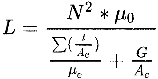
- the invention makes use of a transformer assembly with increased inductance.
- L N 2 * ⁇ 0 ⁇ l A e ⁇ e + G A e ⁇ 0 is a physical constant and cannot be modified.
- the mechanical dimensions of the tranformator assembly are constrained by the size of the ozone generator unit.
- the ferrite core in the transformer assembly has also predefined dimension that cannot be changed.
- the solution of the invention is to change N (number of turns of the primary winding) and G (the airgap of the core).
- the constrain of the mechanical dimension of the generator unit implies that there is no room to increase the number of turns on the secondary winding in the transformer without decreasing the number of turns on the primary winding.
- the solution of the invention was to modify the number of turns on the primary winding, for example by reducing it by a certain number such as reducing it by 1, 2 , 3, 4 or 5 turns from the value currently used in transformer assemblies having an operational frequency of ⁇ 45kHz, being this for example around 14 turns.
- This left enough space to modify the number of turns of the secondary windings for example by increasing it by a certain number such as increasing it by 1, 2 , 3, 4 or 5 turns from the value currently used in transformer assemblies having an operational frequency of ⁇ 45kHz, being this for example around around 107.
- the gap was modified, such as reduced by 0.25, 0.5 0.75, 1, 1.1, 1.2 mm from the value currently used in transformer assemblies having an operational frequency of ⁇ 45kHz, being this for example around 2.1-2.2 mm.
- the third aspect of the invention relates to a transformer assembly comprising a ferrite shell type core surrounding a primary winding and a secondary winding, whererin the primary windings has a number of turns lower than 14 and the secondary winding has a number of turns higher then 107 and the ferrite shell type core has an airgap smaller than 2 mm.
- the operational frequency was decreased from ⁇ 45kHz to ⁇ 30kHz.
- This modification may slightly increase the operational temperature.
- the increase of the operational temperature can be reduced by improved cooling solutions.
- first, second, third and other aspects and embodiments of the present invention may each be combined with any of the other aspects and embodiments.
- Figure 1 shows an ozone generator unit 27 comprising a first PTFE sheet 23 and second PTFE sheet 24 surrounding a high voltage electrode 16.
- the first and a second reaction chamber, in which ozone is generated, are delimited by the first PTFE sheet 23 and second PTFE sheet 24 on one side and the internal surface of the housing or earth electrodes 14 and 15, respectively.
- Oxygen gas enters the ozone generator unit 27 via inlets 19 and 20, is exposed to corona discharge in first and second reaction chambers leading to the formation of ozone gas that is released through ozone outlets 21 and 22, respectively.
- the housing or earth electrodes 14 and 15 are cooled through water cooling flowing in the water cooling chambers 11 and 13.
- the water cooling chambers 11 and 13 are defined by recesses on the external surface of the earth electrodes 14 and 15 covered by covers 10 and 12.
- Stainless steel nets or sheet 25 and 26 are located between the internal surface of the earth electrodes 14 and 15 and the first PTFE sheet 23 and second PTFE sheet 24. Stainless steel nets or sheet 25 and 26 are corona-effect promoting structures promoting discharge between the electrodes.
- Support PTFE rings 17 and 18 are arrange between earth electrodes 14 and 15.
- Support PTFE rings may have the function of spacers, ensuring the formation of reaction chambers between the earth electrodes and the high voltage electrode.
- Figure 2 shows an ozone generator unit 45 comprising a first PTFE sheet 43 and second PTFE sheet 44 surrounding a high voltage electrode 36.
- the first and a second reaction chamber, in which ozone is generated, are delimited by the first PTFE sheet 43 and second PTFE sheet 44 on one side and the internal surface of the housing or earth electrodes 34 and 35, respectively.
- Oxygen gas enters the ozone generator unit 45 via inlets 39 and 40, is exposed to corona discharge in first and second reaction chambers leading to the formation of ozone gas that is released through ozone outlets 41 and 42, respectively.
- the housing or earth electrodes 34 and 35 are cooled through water cooling flowing in the water cooling chambers 31 and 33.
- the water cooling chambers 31 and 33 are defined by recesses on the external surface of the earth electrodes 34 and 35 covered by covers 30 and 32.
- Support PTFE rings 37 and 38 are arrange between earth electrodes 34 and 35.
- the ozone generator unit 45 has the first and second PTFE sheet 43 and 44 in contact with an internal surface of the first and second reaction chamber, i.e. with the internal surface of the earth electrodes 34 and 35.
- This configuration allows for an improved and efficient cooling of the PTFE sheets as being in contact with the internal surface of the earth electrodes that is externally water cooled.
- Figure 3 shows a graph of operational frequency versus weighting audible noise and a ratio between an actual value and a set value of production of ozone production.
- the X axis represents the operational frequency, in Hz, of an ozone generator according to the first aspect of the invention.
- the Y 1 axis is a weighting value of the reduction of audible noise in dBa.
- the line 1 represents a collection of data of ozone generators operated at different frequency versus noise reduction.
- the increase of frequency between 10 kHz and 30 kHz produces a substantial reduction of noise, i.e. up to - 32.5 dBa.
- a further increase to 40 kHz provides a further reduction up to - 37.5 Dba.
- An additional increase in operational frequency does not substantially reduce the noise audible by humans, which is produced by the ozone generator.
- the Y 2 axis is the ratio between an actual value of ozone production and a set value of ozone production O av /O sv at a 200 gr O 3 /Nm 3 ozone concentration, at 2 bars, 100% capacity of ozone release.
- the value 100 on the axis Y 2 represents the condition when the set value corresponds to the actual value, thus for a set value of 200 gr O 3 /Nm 3 , the actual value of ozone released is 200 gr O 3 /Nm 3 .
- Values lower than 100 correspond to conditions in which the set value is higher than the actual ozone release, i.e. less ozone is released compared to the set value.
- Values higher than 100 correspond to conditions in which the set value is lower than the actual ozone release, i.e. more ozone is released compared to the set value.
- Line 2 shows the correspondence between the set values and actual values depending on the operational frequency.
- the correspondent value of 90 means that for a set value of 200 gr O 3 /Nm 3 only 180 gr O 3 /Nm 3 are released.
- Reducing the operational frequency improves the correspondence between the set value and actual value of ozone released.
- the correspondent value of 102 means that for a set value of 200 gr O 3 /Nm 3 , 204 gr O 3 /Nm 3 are released.
- the operational frequency between 30 and 40 kHz was surprisingly found as the frequency providing the lowest audible noise, i.e. the highest reduction in dBa, i.e. between -- 32.5 Dba and - 37.5 Dba.
- the inventors thus configured the ozone generator so as to be operated with a frequency between 30 and 40 kHz.
- the transformer assembly 5 comprises a ferrite core having two parts 3 and 6 separated by a gap pad 7 and a primary and secondary windings 4 and 8.
- Figure 5 is a perspective view of the transformer assembly 5 showed in an exploded view in figure 4 .
- Figure 6 is a flow-chart of a method of operating an ozone generator 9, the ozone generator apparatus according to the first aspect of the invention the method comprising operating the ozone generator apparatus at a frequency between 30 and 40 kHz.
- the operating of the ozone generator comprises:
Description
- The present invention relates to an ozone generator apparatus configured to be operated at an operational frequency range between 30-40 kHz.
- The present invention also relates to a method of operating an ozone generator apparatus at a frequency between 30-40 kHz.
- The present invention also relates to a transformer assembly, such as a high power transformer configured for providing or adapted to provide power within a frequency range between 30-40 kHz.
- Successful ozone water treatment installation depends on the ability of securing the required level of ozone in the water at all times.
- Correct removal of heavy metal from contaminated ground water, appropriate removal of colloidal solids, dissolved organic compounds and transformation of nitrite into nitrate in aquaculture systems and efficient solutions to municipal ozone water treatment issues depend on the ability of securing the required level of ozone in the water at all times.
- Ozone generating apparatus are preferably operated at frequency above the audible range for humans, see for example
WO0220398 WO0053529 WO2008/074767 andUS2001046459A1 , these documents disclose also examples of a transformer to be used with an ozone generating apparatus. - Operating at high frequency is also desirable as having the advantage of requiring lower operating voltages for a given input power compared to low frequency operation, as disclosed, for example, by Kogelschatz in Plasma Chemistry and Plasma processing, ).
- However, ozone generators operating at high frequency do not always secure the release of the required level of ozone. For example, the actual release of ozone, i.e. the concentration of ozone released, may be, in some cases, lower than a set value or lower than the acceptable limits.
- Hence, an improved ozone generator would be advantageous, and in particular a more efficient and reliable ozone generator apparatus able to secure the required level of ozone in the water to be treated at all times, would be advantageous.
- An object of the present invention is to provide an ozone generator apparatus able to secure the required level of ozone in the water to be treated at all times.
- A further object of the present invention is to provide a method of operating an ozone generator apparatus able to secure the required level of ozone in the water to be treated at all times.
- An even further object of the present application is to provide a transformer assembly for powering an ozone generator apparatus able to secure the required level of ozone in the water to be treated at all times.
- An object of the present invention may also be seen as to provide an alternative to the prior art.
- In particular, it may be seen as a further object of the present invention to provide an ozone generator apparatus, a transformer assembly for powering an ozone generator apparatus and a method of operating an ozone generator apparatus that solves the above mentioned problems of the prior art by being configured to be operated at an operational frequency range between 30-40 kHz.
- Thus, the above described object and several other objects are intended to be obtained in a first aspect of the invention by providing an ozone generator apparatus according to
claim 1. - For example, the operational frequency may be between 31 and 37 kHz.
- In search for optimizations in the field of ozone generation, the inventors noticed that the decrease of the frequency of operation increases the productivity of the ozone generator.
- In general, operating at low frequency is not desirable since operating an ozone generator at high frequency has the advantage of lower operating voltages for a given input power.
- Furthermore, the decrease of the operational frequency increases the audible noise produced by the ozone generator unit. Indeed, ozone generating apparatus are preferably operated at frequency way above the audible range for humans. The inventors, in search of optimization in the field of ozone generation, investigated the operational frequency range in connection to the undesired background noise produced during operation and in relation to the optimal ozone release.
- The inventors thus identified a frequency range in which correspondence between set value and actual value of ozone release is optimized for the minimum audible operational disturbance.
- The ozone generator apparatus according the first aspect of the invention comprises a low frequency, high voltage AC power supply, such as a high power transformer or a transformer assembly, configured or adapted to provide between 50 and 800 Watts at a frequency between 30 and 40 kHz to the ozone generator unit.
- For example, the high voltage AC power supply may be configured or adapted to provide between 50 and 800 Watts at a frequency between 31 and 37 kHz.
- The presence of the high voltage AC power supply configured or adapted to provide between 50 and 800 Watts enables the operational frequency between 30 and 40 kHz of the ozone generator unit.
- The high voltage AC power supply of the invention may be referred to herein as high power transformer, as transformer or as transformer assembly.
- In relation to the structure of the ozone generator unit, such as the high voltage electrode unit, the first and second dielectric element and the first and second earth electrode it is referred to structures and elements disclosed in
WO 02/20398 - First and second dielectric elements may be polymer layers, such as thin layer of polymer materials, e.g. sheets of Polytetrafluoroethylene (PTFE).
- In some embodiments, the high voltage electrode unit is located between the first and the second dielectric element.
- The first and the second dielectric element may be located at a distance from the high voltage electrode unit within a range between 0.01 and 0.5 millimeters, such as between 0.01 and 0.4 millimeters, for example between 0.01 and 0.3 millimeters, such as between 0.01 and 0.1.
- In some further embodiments, the first and the second dielectric element may be spaced a part from the high voltage electrode unit by one or more spacer elements.
- The first and the second dielectric element may be spaced a part from the high voltage electrode unit by the one or more spacer elements within 0.01 and 0.5 millimeters, such as between 0.01 and 0.4 millimeters, for example between 0.01 and 0.3 millimeters, such as between 0.01 and 0.1
- The first and second dielectric element may be arranged on both sides of the high voltage electrode.
- In some embodiments, the first and a second earth electrode delimit, with the first and second dielectric, a first and a second reaction chamber.
- The first and second reaction chamber may comprise each an inlet for supplying oxygen gas or oxygen containing gas and an outlet for releasing ozone gas.
- The external surface of the first and second reaction chamber may comprise cooling elements, such as cooling fins.
- In some embodiments, air cooling may be used alone or in combination with water cooling, increasing the efficiency of the ozone generator unit.
- In some other embodiments, water cooling may be used alone for cooling the ozone generator unit.
- The high voltage electrode unit may be arranged as a metallic coating on the first and/or the second dielectric.
- In some other embodiments, the high voltage electrode unit is a metal foil or a metal sheet.
- In some further embodiments, the first and second dielectric element may be in contact with an internal surface of the first and second reaction chamber.
- The specific configuration mentioned above has the advantage that heat produced during ozone production can be dissipated more efficiently as heat exchange between the cooled earth electrodes being part of the first and second reaction chamber and the first and second dielectric elements in contact with the internal surface of the first and second reaction chamber is more efficient.
- In a second aspect, the invention relates to a method of operating an ozone generator apparatus according to
claim 13. - In some embodiments, according to the second aspect of the invention, the operating of the ozone generator apparatus according to the first aspect of the invention comprises: supplying a flow of fluid containing oxygen gas to the ozone generator unit; controlling the flow of fluid containing oxygen gas; controlling a power supplied from a power supply apparatus to the ozone generator at a frequency between 30 and 40 kHz.
- In some embodiments of the method of operating the ozone generator apparatus according to the second aspect of the invention, operating the ozone generator comprises: supplying a flow of fluid containing oxygen gas to the ozone generator; controlling the flow of fluid containing oxygen gas; controlling a power supplied from a power supply apparatus to the ozone generator at a frequency between 30 and 40 kHz.
- In some further embodiments of the first, or second aspect of the invention, the frequency of operation is a frequency between 31 and 40 kHz, such as a frequency between 32 and 35 kHz.
- In a third aspect, the invention relates to a transformer assembly according to
claim 16. - The transformer assembly according to the third aspect comprises a ferrite shell type core surrounding a primary winding and a secondary winding. The primary winding has less than 14 turns and the secondary winding has more than 107 turns. The ferrite shell type core has an air gap smaller than 2.0 mm.
- In some embodiments, the ferrite shell type core comprises at least two parts separated from each other by an air gap smaller than 2.0 mm.
- The inventors devised the high power transformer considering that the operational frequency of the ozone generator unit depends on the capacitance on the reactor and the inductance on the secondary side on the high voltage transformer. The inductance on the primary side on the high voltage transformer and the serial inductance has also some influence on the operational frequency of the ozone generator unit.
- In order to modify the operational frequency the invention makes use of a transformer assembly with increased inductance.
- An approximation of the inductance can be calculated by the formula below:
- In practice, according to the formula above means that no modification on

- The solution of the invention is to change N (number of turns of the primary winding) and G (the airgap of the core).
- However, the constrain of the mechanical dimension of the generator unit implies that there is no room to increase the number of turns on the secondary winding in the transformer without decreasing the number of turns on the primary winding. The solution of the invention was to modify the number of turns on the primary winding, for example by reducing it by a certain number such as reducing it by 1, 2 , 3, 4 or 5 turns from the value currently used in transformer assemblies having an operational frequency of ≈45kHz, being this for example around 14 turns. This left enough space to modify the number of turns of the secondary windings, for example by increasing it by a certain number such as increasing it by 1, 2 , 3, 4 or 5 turns from the value currently used in transformer assemblies having an operational frequency of ≈45kHz, being this for example around around 107.
- Reducing the gap in the transformer increases the magnetic flux in the core. Decreasing the frequency increases the magnetic flux, leading to an increase of the losses in the core. On the other hand decreasing the frequency reduces the number of changes in direction of the flux. This, on the contrary, reduces the losses. In this way, the gap was modified, such as reduced by 0.25, 0.5 0.75, 1, 1.1, 1.2 mm from the value currently used in transformer assemblies having an operational frequency of ≈45kHz, being this for example around 2.1-2.2 mm.
- Thus the third aspect of the invention relates to a transformer assembly comprising a ferrite shell type core surrounding a primary winding and a secondary winding, whererin the primary windings has a number of turns lower than 14 and the secondary winding has a number of turns higher then 107 and the ferrite shell type core has an airgap smaller than 2 mm.
- By decreasing the gap and increasing the number of turns on the secondary winding and decreasing the number of turns on the primary winding the operational frequency was decreased from ≈45kHz to ≈30kHz.
- This modification may slightly increase the operational temperature. However, the increase of the operational temperature can be reduced by improved cooling solutions.
- The first, second, third and other aspects and embodiments of the present invention may each be combined with any of the other aspects and embodiments. These and other aspects of the invention will be apparent from and elucidated with reference to the embodiments described hereinafter.
- It remains, that the scope of the invention is defined by the claims.
- The ozone generator, the method of operating the ozone generator and the transformer assembly according to the invention will now be described in more details with regard to the accompanying figures. The figures show one way of implementing the present invention and are not to be construed as being limiting to other possible embodiments falling within the scope of the attached claim set.
-
Figure 1 shows a cross section of an ozone generator unit according to some embodiments of the invention. -
Figure 2 shows a cross section of an ozone generator unit according to some other embodiments of the invention. -
Figure 3 shows a graph of operational frequency versus weighting audible noise and the ratio between the set value and the actual value of ozone production. -
Figure 4 is an exploded view of the transformer assembly according to some embodiments of the invention. -
Figure 5 is a perspective view of the transformer assembly according to some embodiments of the invention. -
Figure 6 is a flow-chart of a method of operating an ozone generator according to some embodiments of the invention. -
Figure 1 shows anozone generator unit 27 comprising afirst PTFE sheet 23 andsecond PTFE sheet 24 surrounding ahigh voltage electrode 16. - The first and a second reaction chamber, in which ozone is generated, are delimited by the
first PTFE sheet 23 andsecond PTFE sheet 24 on one side and the internal surface of the housing orearth electrodes ozone generator unit 27 viainlets ozone outlets - The housing or
earth electrodes water cooling chambers water cooling chambers earth electrodes covers - Stainless steel nets or
sheet earth electrodes first PTFE sheet 23 andsecond PTFE sheet 24. Stainless steel nets orsheet - Support PTFE rings 17 and 18 are arrange between
earth electrodes - Support PTFE rings may have the function of spacers, ensuring the formation of reaction chambers between the earth electrodes and the high voltage electrode.
-
Figure 2 shows anozone generator unit 45 comprising afirst PTFE sheet 43 andsecond PTFE sheet 44 surrounding ahigh voltage electrode 36. - The first and a second reaction chamber, in which ozone is generated, are delimited by the
first PTFE sheet 43 andsecond PTFE sheet 44 on one side and the internal surface of the housing orearth electrodes ozone generator unit 45 viainlets ozone outlets - The housing or
earth electrodes water cooling chambers water cooling chambers earth electrodes covers - Support PTFE rings 37 and 38 are arrange between
earth electrodes - The
ozone generator unit 45 has the first andsecond PTFE sheet earth electrodes - This configuration allows for an improved and efficient cooling of the PTFE sheets as being in contact with the internal surface of the earth electrodes that is externally water cooled.
-
Figure 3 shows a graph of operational frequency versus weighting audible noise and a ratio between an actual value and a set value of production of ozone production. - The X axis represents the operational frequency, in Hz, of an ozone generator according to the first aspect of the invention.
- The Y1 axis is a weighting value of the reduction of audible noise in dBa.
- The
line 1 represents a collection of data of ozone generators operated at different frequency versus noise reduction. - It can be noticed that the increase of frequency between 10 kHz and 30 kHz produces a substantial reduction of noise, i.e. up to - 32.5 dBa. A further increase to 40 kHz provides a further reduction up to - 37.5 Dba. An additional increase in operational frequency does not substantially reduce the noise audible by humans, which is produced by the ozone generator.
- The Y2 axis is the ratio between an actual value of ozone production and a set value of ozone production Oav/Osv at a 200 gr O3/Nm3 ozone concentration, at 2 bars, 100% capacity of ozone release.
- The
value 100 on the axis Y2 represents the condition when the set value corresponds to the actual value, thus for a set value of 200 gr O3/Nm3, the actual value of ozone released is 200 gr O3/Nm3. Values lower than 100 correspond to conditions in which the set value is higher than the actual ozone release, i.e. less ozone is released compared to the set value. - Values higher than 100 correspond to conditions in which the set value is lower than the actual ozone release, i.e. more ozone is released compared to the set value.
-
Line 2 shows the correspondence between the set values and actual values depending on the operational frequency. - It can be noticed that the higher the operational frequency, the worse the correspondence between the set value and the actual value of ozone released.
- Indeed at high frequency, e.g. at 60 kHz, the correspondent value of 90 means that for a set value of 200 gr O3/Nm3 only 180 gr O3/Nm3 are released.
- Reducing the operational frequency improves the correspondence between the set value and actual value of ozone released.
- For example, for an operational frequency of 30 kHz, the correspondent value of 102 means that for a set value of 200 gr O3/Nm3, 204 gr O3/Nm3 are released. Within the acceptable limits of deviation between set and actual value, i.e. 100 +/- 2, the operational frequency between 30 and 40 kHz was surprisingly found as the frequency providing the lowest audible noise, i.e. the highest reduction in dBa, i.e. between -- 32.5 Dba and - 37.5 Dba.
- The inventors thus configured the ozone generator so as to be operated with a frequency between 30 and 40 kHz.
- In
figure 4 , thetransformer assembly 5 according to some embodiments of the invention comprises a ferrite core having twoparts 3 and 6 separated by agap pad 7 and a primary andsecondary windings 4 and 8. -
Figure 5 is a perspective view of thetransformer assembly 5 showed in an exploded view infigure 4 . -
Figure 6 is a flow-chart of a method of operating anozone generator 9, the ozone generator apparatus according to the first aspect of the invention the method comprising operating the ozone generator apparatus at a frequency between 30 and 40 kHz. - The operating of the ozone generator comprises:
- S1, supplying a flow of fluid containing oxygen gas to the ozone generator;
- S2, controlling the flow of fluid containing oxygen gas;
- S3, controlling a power supplied from a power supply apparatus to the ozone generator at a frequency between 30 and 40 kHz.
- Although the present invention has been described in connection with the specified embodiments, it should not be construed as being in any way limited to the presented examples. The scope of the present invention is set out by the accompanying claim set. In the context of the claims, the terms "comprising" or "comprises" do not exclude other possible elements or steps. Also, the mentioning of references such as "a" or "an" etc. should not be construed as excluding a plurality. The use of reference signs in the claims with respect to elements indicated in the figures shall also not be construed as limiting the scope of the invention.
Claims (16)
- An ozone generator apparatus comprising- an ozone generator unit (27, 45) comprising∘ a high voltage electrode unit (16, 36);∘ a first (23, 43) and second dielectric element (24, 44);∘ a first (14, 34) and second earth electrode (15, 35);wherein said high voltage electrode unit is located between said first and said second dielectric element- wherein said generator unit is configured to be operated at an operational frequency range between 30 and 40 kHz;characterised in thatthe apparatus further comprises:- a low frequency, high voltage AC power supply, being a transformer assembly, configured to provide between 50 and 800 Watts at a frequency between 30 and 40 kHz to the ozone generator unit.
- An ozone generator apparatus according to any of the preceding claims, wherein said first and second dielectric element are located at a distance from said high voltage electrode unit within a range between 0.01 and 0.1 millimeters, such as between 0.01 and 0.075 millimeters.
- An ozone generator apparatus according to any of the preceding claims, wherein said first and second dielectric element are spaced apart from said high voltage electrode unit by one or more spacer elements.
- An ozone generator apparatus according to any of the preceding claims, wherein said first and second dielectric element are arranged on both sides of said high voltage electrode unit.
- An ozone generator apparatus according to any of the preceding claims, wherein said first and a second earth electrode delimit a first and a second reaction chamber with said first and second dielectric element.
- An ozone generator apparatus according to any of the preceding claims wherein said high voltage electrode unit is arranged as a metallic coating on said first and said second dielectric element.
- An ozone generator apparatus according to any of the preceding claims 1-5, wherein said high voltage electrode unit is a metal foil or a metal sheet.
- An ozone generator apparatus according to any of claims 5-7, wherein said first and second reaction chamber comprise each at least an inlet (19, 20, 39, 40) for supplying oxygen gas or oxygen containing gas and at least an outlet (21, 22, 41, 42) for releasing ozone gas.
- An ozone generator apparatus according to any of claims 5-8, wherein an external surface of said first and second chamber comprises cooling elements, such as cooling fins.
- An ozone generator apparatus according to any of claims 5 to 9, wherein said first and second dielectric element are in contact with an internal surface of said first and second reaction chamber.
- An ozone generator apparatus according to any of the preceding claims wherein said transformer assembly is a high power transformer.
- An ozone generator apparatus according to any of the preceding claims wherein said transformer assembly is a high power transformer comprising a ferrite shell type core surrounding a primary winding and a secondary winding, whererin said primary winding has a number of turns lower than 14 and said secondary winding has a number of turns higher than 107 and said ferrite shell type core has an airgap smaller than 2 mm.
- A method of operating an ozone generator apparatus, said ozone generator apparatus according to any of the preceding claims 1-12, said method comprising:- - operating said ozone generator apparatus at a frequency between 30 and 40 kHz.
- A method of operating an ozone generator apparatus according to claim 13, wherein said operating step comprises:- supplying a flow of fluid containing oxygen gas to said ozone generator apparatus;- controlling said flow of fluid containing oxygen gas;- controlling a power supplied from the power supply to said ozone generator at a frequency between 30 and 40 kHz.
- A method of operating an ozone generator apparatus according to any of the preceding claims 13-14, wherein said frequency is a frequency between 31 and 40 kHz, such as a frequency between 32 and 35 kHz.
- A transformer assembly, being a high power transformer configured to provide electrical power between 50 and 800 Watt within a frequency range between 30 and 40 kHz to the ozone generator of any of claims 1-12, said transformer assembly comprising a ferrite shell type core surrounding a primary winding and a secondary winding, wherein said primary winding has a number of turns lower than 14 and said secondary winding has a number of turns higher than 107 and said ferrite shell type core has an airgap smaller than 2 mm.
Priority Applications (1)
| Application Number | Priority Date | Filing Date | Title |
|---|---|---|---|
| EP23176963.9A EP4235710A3 (en) | 2019-02-25 | 2020-02-24 | A low frequency ozone generator |
Applications Claiming Priority (2)
| Application Number | Priority Date | Filing Date | Title |
|---|---|---|---|
| EP19159104 | 2019-02-25 | ||
| PCT/EP2020/054753 WO2020173865A1 (en) | 2019-02-25 | 2020-02-24 | A low frequency ozone generator |
Related Child Applications (1)
| Application Number | Title | Priority Date | Filing Date |
|---|---|---|---|
| EP23176963.9A Division EP4235710A3 (en) | 2019-02-25 | 2020-02-24 | A low frequency ozone generator |
Publications (3)
| Publication Number | Publication Date |
|---|---|
| EP3932149A1 EP3932149A1 (en) | 2022-01-05 |
| EP3932149B1 true EP3932149B1 (en) | 2023-06-07 |
| EP3932149C0 EP3932149C0 (en) | 2023-06-07 |
Family
ID=65576211
Family Applications (2)
| Application Number | Title | Priority Date | Filing Date |
|---|---|---|---|
| EP23176963.9A Pending EP4235710A3 (en) | 2019-02-25 | 2020-02-24 | A low frequency ozone generator |
| EP20706719.0A Active EP3932149B1 (en) | 2019-02-25 | 2020-02-24 | A low frequency ozone generator |
Family Applications Before (1)
| Application Number | Title | Priority Date | Filing Date |
|---|---|---|---|
| EP23176963.9A Pending EP4235710A3 (en) | 2019-02-25 | 2020-02-24 | A low frequency ozone generator |
Country Status (17)
| Country | Link |
|---|---|
| US (1) | US20220135405A1 (en) |
| EP (2) | EP4235710A3 (en) |
| JP (1) | JP2022522062A (en) |
| KR (1) | KR20210130767A (en) |
| CN (1) | CN113475166A (en) |
| AU (1) | AU2020227180A1 (en) |
| BR (1) | BR112021016535A2 (en) |
| CA (1) | CA3130136A1 (en) |
| CL (1) | CL2021002240A1 (en) |
| EA (1) | EA202192243A1 (en) |
| ES (1) | ES2951972T3 (en) |
| HU (1) | HUE062995T2 (en) |
| MX (1) | MX2021010156A (en) |
| PL (1) | PL3932149T3 (en) |
| SG (1) | SG11202108143TA (en) |
| WO (1) | WO2020173865A1 (en) |
| ZA (1) | ZA202105981B (en) |
Citations (10)
| Publication number | Priority date | Publication date | Assignee | Title |
|---|---|---|---|---|
| EP0200313B1 (en) | 1985-04-01 | 1990-01-17 | Honeywell Inc. | Forceless non-contacting power transformer |
| WO1994004011A1 (en) | 1992-08-01 | 1994-02-17 | Coolite Limited | Fluorescent tube driver and lighting system |
| WO2000053529A1 (en) | 1999-03-05 | 2000-09-14 | Ozonator Limited | Ozone generator and a method for generation of ozone |
| KR100302357B1 (en) | 1999-05-19 | 2001-10-29 | 손동준 | a corona discharge device for ozone generating and which method thereof |
| US20010046459A1 (en) | 1999-09-21 | 2001-11-29 | St. Onge Benedict B. | High efficiency ozone generator |
| WO2002020398A1 (en) | 2000-09-06 | 2002-03-14 | Ozonator Limited | Electrode unit for use in ozone generator and ozone generator |
| EP0901136B1 (en) | 1997-09-04 | 2003-06-25 | TDK Corporation | Inductance device with gap |
| JP5193086B2 (en) | 2008-07-04 | 2013-05-08 | 株式会社荏原製作所 | Discharge cell discharge circuit and discharge cell discharge circuit control system |
| US20130257301A1 (en) | 2012-03-28 | 2013-10-03 | Mks Instruments, Inc. | Compact, configurable power supply for energizing ozone-producing cells |
| WO2018025133A1 (en) | 2016-08-05 | 2018-02-08 | Ozone Inventions Limited | Ozone generator unit and system |
Family Cites Families (5)
| Publication number | Priority date | Publication date | Assignee | Title |
|---|---|---|---|---|
| JP4948007B2 (en) * | 2006-03-22 | 2012-06-06 | 住友精密工業株式会社 | Discharge cell for ozone generator |
| ES2852223T3 (en) | 2006-12-20 | 2021-09-13 | Primozone Production Ab | High voltage transformer |
| CA2764215C (en) * | 2010-12-21 | 2014-03-18 | Kabushiki Kaisha Toshiba | Ozone generating apparatus |
| JP6380745B2 (en) * | 2013-08-29 | 2018-08-29 | Tdk株式会社 | Trance |
| US10917971B2 (en) * | 2016-11-17 | 2021-02-09 | Sony Corporation | Electronic component, power supply device, and method of manufacturing coil |
-
2020
- 2020-02-24 EP EP23176963.9A patent/EP4235710A3/en active Pending
- 2020-02-24 KR KR1020217030206A patent/KR20210130767A/en not_active Application Discontinuation
- 2020-02-24 EP EP20706719.0A patent/EP3932149B1/en active Active
- 2020-02-24 AU AU2020227180A patent/AU2020227180A1/en active Pending
- 2020-02-24 BR BR112021016535-5A patent/BR112021016535A2/en unknown
- 2020-02-24 EA EA202192243A patent/EA202192243A1/en unknown
- 2020-02-24 CA CA3130136A patent/CA3130136A1/en active Pending
- 2020-02-24 MX MX2021010156A patent/MX2021010156A/en unknown
- 2020-02-24 PL PL20706719.0T patent/PL3932149T3/en unknown
- 2020-02-24 JP JP2021572703A patent/JP2022522062A/en active Pending
- 2020-02-24 HU HUE20706719A patent/HUE062995T2/en unknown
- 2020-02-24 CN CN202080016326.7A patent/CN113475166A/en active Pending
- 2020-02-24 ES ES20706719T patent/ES2951972T3/en active Active
- 2020-02-24 WO PCT/EP2020/054753 patent/WO2020173865A1/en active Search and Examination
- 2020-02-24 SG SG11202108143TA patent/SG11202108143TA/en unknown
- 2020-02-24 US US17/310,724 patent/US20220135405A1/en active Pending
-
2021
- 2021-08-19 ZA ZA2021/05981A patent/ZA202105981B/en unknown
- 2021-08-25 CL CL2021002240A patent/CL2021002240A1/en unknown
Patent Citations (10)
| Publication number | Priority date | Publication date | Assignee | Title |
|---|---|---|---|---|
| EP0200313B1 (en) | 1985-04-01 | 1990-01-17 | Honeywell Inc. | Forceless non-contacting power transformer |
| WO1994004011A1 (en) | 1992-08-01 | 1994-02-17 | Coolite Limited | Fluorescent tube driver and lighting system |
| EP0901136B1 (en) | 1997-09-04 | 2003-06-25 | TDK Corporation | Inductance device with gap |
| WO2000053529A1 (en) | 1999-03-05 | 2000-09-14 | Ozonator Limited | Ozone generator and a method for generation of ozone |
| KR100302357B1 (en) | 1999-05-19 | 2001-10-29 | 손동준 | a corona discharge device for ozone generating and which method thereof |
| US20010046459A1 (en) | 1999-09-21 | 2001-11-29 | St. Onge Benedict B. | High efficiency ozone generator |
| WO2002020398A1 (en) | 2000-09-06 | 2002-03-14 | Ozonator Limited | Electrode unit for use in ozone generator and ozone generator |
| JP5193086B2 (en) | 2008-07-04 | 2013-05-08 | 株式会社荏原製作所 | Discharge cell discharge circuit and discharge cell discharge circuit control system |
| US20130257301A1 (en) | 2012-03-28 | 2013-10-03 | Mks Instruments, Inc. | Compact, configurable power supply for energizing ozone-producing cells |
| WO2018025133A1 (en) | 2016-08-05 | 2018-02-08 | Ozone Inventions Limited | Ozone generator unit and system |
Also Published As
| Publication number | Publication date |
|---|---|
| KR20210130767A (en) | 2021-11-01 |
| EA202192243A1 (en) | 2022-02-08 |
| EP4235710A3 (en) | 2023-10-18 |
| ZA202105981B (en) | 2023-04-26 |
| CN113475166A (en) | 2021-10-01 |
| CL2021002240A1 (en) | 2022-03-04 |
| EP4235710A2 (en) | 2023-08-30 |
| WO2020173865A1 (en) | 2020-09-03 |
| ES2951972T3 (en) | 2023-10-26 |
| BR112021016535A2 (en) | 2021-10-26 |
| PL3932149T3 (en) | 2023-12-04 |
| AU2020227180A1 (en) | 2021-10-07 |
| EP3932149A1 (en) | 2022-01-05 |
| MX2021010156A (en) | 2021-09-14 |
| EP3932149C0 (en) | 2023-06-07 |
| US20220135405A1 (en) | 2022-05-05 |
| SG11202108143TA (en) | 2021-08-30 |
| CA3130136A1 (en) | 2020-09-03 |
| HUE062995T2 (en) | 2023-12-28 |
| JP2022522062A (en) | 2022-04-13 |
Similar Documents
| Publication | Publication Date | Title |
|---|---|---|
| EP0884928B1 (en) | Induction heating apparatus for fluids | |
| US3214364A (en) | Ozone generator | |
| TW201501775A (en) | Toroidal plasma abatement apparatus and method | |
| CA2280555C (en) | Ozonizing unit, ozone generator and ozone-processing system | |
| EP3932149B1 (en) | A low frequency ozone generator | |
| US10343940B1 (en) | Systems and methods for treating industrial feedwater | |
| US10336612B2 (en) | Ozone generator unit and system | |
| CN209576241U (en) | The device of double-dielectric barrier discharge plasma excitation catalytic gas phase reaction processing organic exhaust gas | |
| EA044703B1 (en) | LOW FREQUENCY OZONE GENERATOR | |
| US20220009777A1 (en) | Systems and methods for generating ozone | |
| TWI690483B (en) | Ozone gas generation system and ozone gas generation method | |
| KR102284696B1 (en) | How to control an ozone generator | |
| EP3517498B1 (en) | Compact ozone generator with multi-gap electrode assembly | |
| KR20130119131A (en) | Apparatus for sterilization using potocatalyst and high voltage pulse and sterilization method | |
| RU2239597C1 (en) | Device for generation of ozone | |
| WO2002058839A1 (en) | Method of sewage treatment and decontamination | |
| US20210317011A1 (en) | Treatment reactor and method of treating a liquid | |
| JPH0781904A (en) | Multiple-cylinder ozonizer | |
| JPH07277709A (en) | Ozone generator | |
| JP2005263532A (en) | Ozone generating apparatus | |
| WO2022178422A1 (en) | Systems and methods for magnetic heat induction and exchange to mobile streams of matter | |
| JPH01153502A (en) | Ozonizer | |
| CN112830455A (en) | Microwave discharge method singlet oxygen generator and method | |
| RU2379860C1 (en) | Transformer plasma generator with dielectric discharge chamber | |
| JP2002362907A (en) | Ozonizer |
Legal Events
| Date | Code | Title | Description |
|---|---|---|---|
| STAA | Information on the status of an ep patent application or granted ep patent |
Free format text: STATUS: UNKNOWN |
|
| STAA | Information on the status of an ep patent application or granted ep patent |
Free format text: STATUS: THE INTERNATIONAL PUBLICATION HAS BEEN MADE |
|
| STAA | Information on the status of an ep patent application or granted ep patent |
Free format text: STATUS: THE INTERNATIONAL PUBLICATION HAS BEEN MADE |
|
| PUAI | Public reference made under article 153(3) epc to a published international application that has entered the european phase |
Free format text: ORIGINAL CODE: 0009012 |
|
| STAA | Information on the status of an ep patent application or granted ep patent |
Free format text: STATUS: REQUEST FOR EXAMINATION WAS MADE |
|
| 17P | Request for examination filed |
Effective date: 20210917 |
|
| AK | Designated contracting states |
Kind code of ref document: A1 Designated state(s): AL AT BE BG CH CY CZ DE DK EE ES FI FR GB GR HR HU IE IS IT LI LT LU LV MC MK MT NL NO PL PT RO RS SE SI SK SM TR |
|
| DAV | Request for validation of the european patent (deleted) | ||
| DAX | Request for extension of the european patent (deleted) | ||
| REG | Reference to a national code |
Ref country code: HK Ref legal event code: DE Ref document number: 40063631 Country of ref document: HK |
|
| GRAP | Despatch of communication of intention to grant a patent |
Free format text: ORIGINAL CODE: EPIDOSNIGR1 |
|
| STAA | Information on the status of an ep patent application or granted ep patent |
Free format text: STATUS: GRANT OF PATENT IS INTENDED |
|
| INTG | Intention to grant announced |
Effective date: 20221114 |
|
| GRAS | Grant fee paid |
Free format text: ORIGINAL CODE: EPIDOSNIGR3 |
|
| GRAA | (expected) grant |
Free format text: ORIGINAL CODE: 0009210 |
|
| STAA | Information on the status of an ep patent application or granted ep patent |
Free format text: STATUS: THE PATENT HAS BEEN GRANTED |
|
| AK | Designated contracting states |
Kind code of ref document: B1 Designated state(s): AL AT BE BG CH CY CZ DE DK EE ES FI FR GB GR HR HU IE IS IT LI LT LU LV MC MK MT NL NO PL PT RO RS SE SI SK SM TR |
|
| REG | Reference to a national code |
Ref country code: GB Ref legal event code: FG4D |
|
| REG | Reference to a national code |
Ref country code: CH Ref legal event code: EP Ref country code: AT Ref legal event code: REF Ref document number: 1578470 Country of ref document: AT Kind code of ref document: T Effective date: 20230615 Ref country code: DE Ref legal event code: R096 Ref document number: 602020011900 Country of ref document: DE |
|
| U01 | Request for unitary effect filed |
Effective date: 20230619 |
|
| U07 | Unitary effect registered |
Designated state(s): AT BE BG DE DK EE FI FR IT LT LU LV MT NL PT SE SI Effective date: 20230626 |
|
| REG | Reference to a national code |
Ref country code: NO Ref legal event code: T2 Effective date: 20230607 |
|
| REG | Reference to a national code |
Ref country code: LT Ref legal event code: MG9D |
|
| REG | Reference to a national code |
Ref country code: ES Ref legal event code: FG2A Ref document number: 2951972 Country of ref document: ES Kind code of ref document: T3 Effective date: 20231026 |
|
| REG | Reference to a national code |
Ref country code: GR Ref legal event code: EP Ref document number: 20230401457 Country of ref document: GR Effective date: 20231010 |
|
| PG25 | Lapsed in a contracting state [announced via postgrant information from national office to epo] |
Ref country code: RS Free format text: LAPSE BECAUSE OF FAILURE TO SUBMIT A TRANSLATION OF THE DESCRIPTION OR TO PAY THE FEE WITHIN THE PRESCRIBED TIME-LIMIT Effective date: 20230607 Ref country code: HR Free format text: LAPSE BECAUSE OF FAILURE TO SUBMIT A TRANSLATION OF THE DESCRIPTION OR TO PAY THE FEE WITHIN THE PRESCRIBED TIME-LIMIT Effective date: 20230607 |
|
| REG | Reference to a national code |
Ref country code: HU Ref legal event code: AG4A Ref document number: E062995 Country of ref document: HU |
|
| PG25 | Lapsed in a contracting state [announced via postgrant information from national office to epo] |
Ref country code: SK Free format text: LAPSE BECAUSE OF FAILURE TO SUBMIT A TRANSLATION OF THE DESCRIPTION OR TO PAY THE FEE WITHIN THE PRESCRIBED TIME-LIMIT Effective date: 20230607 |
|
| PG25 | Lapsed in a contracting state [announced via postgrant information from national office to epo] |
Ref country code: SM Free format text: LAPSE BECAUSE OF FAILURE TO SUBMIT A TRANSLATION OF THE DESCRIPTION OR TO PAY THE FEE WITHIN THE PRESCRIBED TIME-LIMIT Effective date: 20230607 Ref country code: SK Free format text: LAPSE BECAUSE OF FAILURE TO SUBMIT A TRANSLATION OF THE DESCRIPTION OR TO PAY THE FEE WITHIN THE PRESCRIBED TIME-LIMIT Effective date: 20230607 Ref country code: RO Free format text: LAPSE BECAUSE OF FAILURE TO SUBMIT A TRANSLATION OF THE DESCRIPTION OR TO PAY THE FEE WITHIN THE PRESCRIBED TIME-LIMIT Effective date: 20230607 |
|
| REG | Reference to a national code |
Ref country code: DE Ref legal event code: R026 Ref document number: 602020011900 Country of ref document: DE |
|
| PLBI | Opposition filed |
Free format text: ORIGINAL CODE: 0009260 |
|
| PLAB | Opposition data, opponent's data or that of the opponent's representative modified |
Free format text: ORIGINAL CODE: 0009299OPPO |
|
| U20 | Renewal fee paid [unitary effect] |
Year of fee payment: 5 Effective date: 20240222 |
|
| PLAX | Notice of opposition and request to file observation + time limit sent |
Free format text: ORIGINAL CODE: EPIDOSNOBS2 |
|
| PGFP | Annual fee paid to national office [announced via postgrant information from national office to epo] |
Ref country code: GR Payment date: 20240221 Year of fee payment: 5 |
|
| PGFP | Annual fee paid to national office [announced via postgrant information from national office to epo] |
Ref country code: IS Payment date: 20240212 Year of fee payment: 5 |
|
| 26 | Opposition filed |
Opponent name: XYLEM EUROPE GMBH Effective date: 20240305 Opponent name: PROMINENT GMBH Effective date: 20240304 |
|
| PGFP | Annual fee paid to national office [announced via postgrant information from national office to epo] |
Ref country code: IE Payment date: 20240220 Year of fee payment: 5 |
|
| R26 | Opposition filed (corrected) |
Opponent name: XYLEM EUROPE GMBH Effective date: 20240305 Opponent name: PROMINENT GMBH Effective date: 20240304 |